

GE 10231 Owner's Manual
HALOGEN LINKABLE LIGHT BAR
Your GE Halogen Light Bar is the perfect under cabinet lighting solution for kitchens, bathrooms,
bookcases, entertainment centers, and study areas. We recommend you read through the instructions entirely
before starting your installation in order to help you understand all the steps and options regarding your
particular installation. If you are unfamiliar with the electrical codes in your region, or do not feel capable of
safely installing this product, we recommend you call a qualified electrician for assistance with your
installation.
The Halogen Linkable Light Bar comes with a line cord, and the necessary hardware to install the fixture. The
package also includes a link cable for linking with other GE Halogen Linkable Bars. Each bar has an integral
3-position switch (LO, OFF, HI) which controls only its own bulbs. Additional bars can be purchased
separately and added to your lighting system at any time.
The maximum number of Light Bars in your chain must not exceed 8.
The Halogen bar is intended for under cabinet, or under shelf installations ONLY. DO NOT install these bars
INSIDE cabinets. DO NOT attempt to install while plugged in. These bars are for indoor use only and can be
mounted to cabinets and surfaces having a material thickness of at least 1/4". NOT for use with plastic
cabinets. DO NOT mount over sinks or stoves. Mount with lamp facing down.
Your GE Halogen fixture is linkable, allowing you to ”daisychain” multiple Light Bars under your
cabinets, but still only use one outlet to power all your GE Halogen Light Bars.
The Halogen bulb used in your fixture is a 120V/20 Watt bulb with G8 Base.
The bulb will get quite hot during normal operation. The materials used in the construction of the Halogen
Light Bar have been tested to with stand these high temperatures. However, you should pay particular
attention to the mounting recommendations as follows:
1. Your Light Bar comes with a 5 foot cord. Make sure your line cord can reach a nearby electrical outlet.
2. Make sure that flammable, or objects that can melt are at least 12” or more away from the fixture.
CAUTION: Do not plug the line cord into an electrical outlet at this time. Do not attach the
individual Halogen bars to an electrically live cord.
Mounting Instructions
Carefully plan out your installation prior to actually securing your Halogen Light Bar to the
mounting surface making sure that your 5 ft. line cord will reach the nearest electrical outlet.
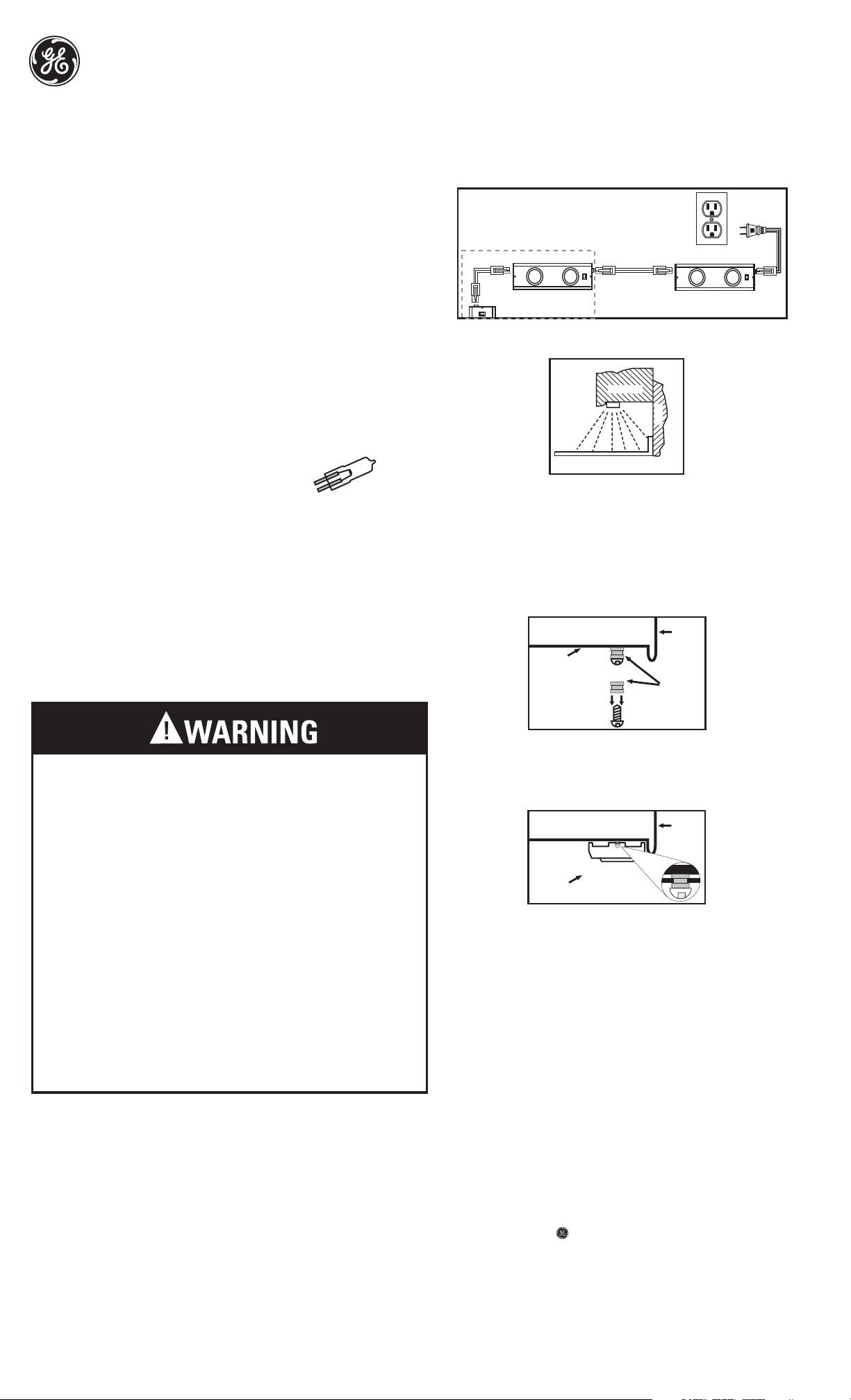
The line cord is capable of handling up to 8 Halogen Light Bars (FIG. 1).
For kitchen installations, the recommended mounting for the Light Bars near the front lip of your
kitchen under cabinets as shown in the illustration (FIG. 2) This provides the best light
distribution across a countertop.
ELECTRICAL CORD CAN BE ROUTED AROUND
CORNERS TO SUIT THE INSTALLATION
2 Pin 3 Pin 3 Pin 2 Pin
3 Pin
FIG. 1
OPTIONAL FIXTURES
CABINET
W L L A
Lamp Replacement Instructions
Relamp only with a 120V, 20W MAX or less halogen bulb with G8 base.
1. Turn the light fixture off, and allow sufficient time for the unit and bulb
(lamp) to cool properly before handling.
2. Remove the glass lens by turning the outer ring counter clockwise.
When the lens lock is undone, the glass lens and ring will drop into your hand.
Be careful not to drop the lens—it can break!
3. Using a cloth or paper towel, grasp the bulb firmly and pull bulb out of the socket.
Re-insert a new bulb using a paper towel or cloth to hold the bulb.
4. Position the glass lens so the catches line up with the corresponding openings in the light fixture, and
re-attach the lens by twisting on in a clock-wise motion.
IMPORTANT SAFETY INSTRUCTIONS
This unit has a polarized plug (one blade is wider than the other) as a safety feature. This
plug will fit in a polarized outlet only one way. If the plug does not fit fully into the outlet,
reverse the plug. If it still does not fit, contact a qualified electrician. Never use with an
extension cord unless plug can be fully inserted. DO NOT attempt to defeat this feature.
WARNINGS TO REDUCE THE RISK OF FIRE, ELECTRIC SHOCK, EXPOSURE TO EXCESSIVE
UV RADIATION, OR INJURY TO PERSONS:
Risk of electric shock
-Use only insulated staples or plastic wire guides to secure the cords.
-Route and secure the cords so that they will not be pinched or damaged
Risk of fire
-Keep away from materials that may burn.
-Use only with a 120V 20W MAX or less Halogen Bulb with G8 Base
-Not intended for installation in plastic cabinets.
-Keep cord or combustibles such as plastic, paper goods, and the like away from
glass lens and hot lamp.
-Position under cabinet light with respect to cabinet/shelf to permit reading of the
lamp replacement markings during relamping. Mount Light Bar facing down.
-Not intended for illumination of aquariums.
-Not intended for recessed installation in ceilings or soffits.
-Not intended for surface installation inside built-in furnishings such as kitchen
cabinets, china cabinets, or trophy cases.
-Do not conceal power supply cord inside a wall, ceiling, soffit, kitchen cabinet,
or similar permanent structure.
-Do not run the power supply cord through holes in walls, ceilings, or floors.
Risk of personal injury
-Turn off/unplug and allow to cool before replacing the bulb
-Bulb and glass lens gets HOT quickly!
-Lighted lamp and lens are HOT!
-Do not touch hot lens or enclosure.
-Do not remain in light if skin feels warm.
-Do not look directly at lighted bulb.
-Do not operate the unit with a missing or damaged glass lens.
-Do not install on walls or vertical surfaces.
20 Watt MAX
or less
Halogen Bulb
with G8 Base
SAVE THESE INSTRUCTIONS IN A LOCATION CLOSE TO YOUR CABINET SO
YOU CAN REFER TO THEM AT A LATER TIME.
Cleaning Instructions
Your fixture is made from quality materials that will last for many, many years with a minimum of
care. When cleaning, make sure you have unplugged your fixture, and have allowed sufficient
time for the unit to cool to room temperature. You should clean the housing and lense using a
mild non-abrasive cleaner, and soft cloth. Do not spray liquid cleaner directly on the fixture, or
lense. Also, do not spray cleaner onto the switch, fused line cord, or lamp. You should plug your
fixture back in only after the fixture has thoroughly dried.
COUNTER TOP
FIG. 2
1. Locate positions where Halogen bars should be mounted, keeping in mind that the linking
cords can handle a maximum of 18”. between bars (FIG. 1).
2. Use the enclosed template to mark the appropriate screw hole locations. Pre-drill holes in
the mounting surface with a 3/32” drill bit for hardwood, use a 5/64” drill bit for softwood.
NOTE: The screw locations must be exact for the light bar to mount properly.
3. Place the two small rubber grommets over the mounting screws. Screw in the two #8
mounting screws until the rubber grommets contact the bottom surface of the cabinet.
The turn the screws another 1/4 turn. The screws must be driven in straight for the
light bar to mount properly. (FIG. 3).
Front of
Mounting
Surface
Cabinet
Grommet
FIG. 3
4. Align the cross hole openings in the bottom plate of the light bar over the mounting screws,
and firmly slide the light bar over in one direction to lock it into place. The light bar can
slide toward the front, rear, or from side to side depending on the spacing in your particular
installation. The light bar should fit snugly up against the mounting surface. If not, then your
screws need to be tightened a little more for an improved fit (FIG. 4).
Front of
Cabinet
Halogen
Bar
FIG. 4
5. Your line cord has a molded plastic cap on one end, and a link connector at the other end.
The link connector plugs into your halogen bar. The second cord provided is a linking cord
with link connectors on both ends. This is used to connect your halogen bar to the
next bar in your chain. Link adjacent only. See FIG 1 to see how 2 pin and 3 pin plugs
are intended to be used.
Attaching Additional Bars at a Later Date
If you desire additional bars for your system after the initial installation, you may attach them as
needed (sold separately) by following these instructions. Keep in mind the maximum linking
distance between bars is 2 ft. In addition, make sure not to exceed the 8 bars per line
cord limit for your total installation.
CAUTION: DO NOT ATTEMPT TO ATTACH ADDITIONAL BARS TO YOUR EXISTING SYSTEM
WITHOUT UNPLUGGING THE LINE CORD FROM THE ELECTRICAL OUTLET OR DISCONNECTING
THE ELECTRICITY AT THE ELECTRICAL POWER PANEL.
1. Install the additional Halogen Light Bar following steps 1-5 of the mounting instructions.
2. Once installed, attach the linking cord between the last Light Bar (prevoiusly installed) and
the new one. See FIG. 1 below to see how the 2 pin and 3 pin plugs are intended to be used.
3. When adding a Light Bar to an existing system of linked bars, the line cord (with the
power plug) is not needed. Only the first Light Bar in the chain needs to be connected to
power with the line cord.
is a trademark of the
General Electric Company
and is used under license to
Jasco Products Company LLC,
10 E. Memorial Road
Oklahoma City, OK 73114.
Or visit us at www.jascoproducts.com.
LINKABLE
Halogen LIGHT BARS
10231-4
10233-4
UCH 2B 120
UCH 3B 120
 Loading...