

GE 10113 GE UCF, 10142 GE UCF, 10143 GE UCF, 16029 GE UCF, 16687 GE UCF Owner's Manual
WARNING
Risk of electric shock
- Do not use in wet locations.
- Use indoors only.
- Turn power off before servicing -- see instructions.
- Properly ground fixture.
- Ensure that no bare wires are exposed outside the electrical
connections.
Risk of injury
- Bulb may shatter and cause injury if broken.
- Do not use excessive force when installing bulb.
- Some metal parts in the fixture may have sharp edges. To prevent
cuts and scrapes, wear gloves when handling the parts.
- Account for small parts and destroy packing material, as these
may be hazardous to children.
Risk of burn
- Allow bulb to cool before handling.
Risk of fire
- Minimum 90º C supply conductors.
- Not intended for illumination of aquariums.
- Not intended for use above stoves, cook tops, or sinks.
- Not intended for recessed installation in ceilings or soffits.
- Not intended for surface installation inside or on top of built-in
furnishings such as kitchen cabinets, china cabinets, or trophy
cases.
ADVERTENCIA
Riesgo de descarga eléctrica
- No usar en lugares húmedos.
- Usar en espacios interiores solamente.
- Desconectar la alimentación antes de la limpieza o la reparación: ver
instrucciones.
- Realizar la correspondiente conexión a tierra.
- No dejar cables desnudos expuestos por fuera de las conexiones
eléctricas.
Riesgo de lesiones
- La bombilla se puede romper en trozos pequeños y provocar lesiones.
- No aplicar demasiada fuerza al instalar la bombilla.
- Algunas partes metálicas de esta unidad pueden tener bordes filosos.
Para evitar cortes y raspaduras, use guantes al manipular las piezas.
- Recoger todas las piezas pequeñas y destruir el material de embalaje,
dado que éstos pueden ser peligrosos para los niños.
Riesgo de quemaduras
- Dejar que la bombilla se enfríe antes de manipularla.
Riesgo de incendio
- Conductores de alimentación de 90º C como mínimo.
- No está diseñada para la iluminación de acuarios.
- No está diseñada para usar sobre estufas, hornillas o fregaderos.
- No está diseñada para instalaciones empotradas en cielos rasos o
techos falsos.
- No está diseñada para instalación en superficie dentro o encima de
muebles empotrados, como gabinetes de cocina, gabinetes de
porcelana o vitrinas.
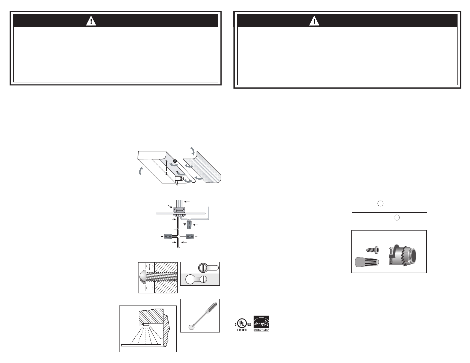
INSTALLATION PROCEDURES
Note: For kitchen installations, the recommended mounting for the fluorescent light fixture
is near the front lip of your kitchen under cabinets as shown in the illustration. The bulb will
face the wall/backsplash. See Figure 6. This provides the best light distribution across a
countertop.
1) Consult a local licensed electrician or electrical contractor if you are not sure about the
installation.
2) Ensure that electricity is TURNED OFF at the main circuit breaker or fuse box. DO NOT
ATTEMPT TO INSTALL FIXTURE WITH THE POWER ON.
3) Select a suitable dry mounting location (for indoor use only). Make sure the mounting
surface is capable of supporting the fixture.
4) Remove the lens/diffuser by lightly pulling the rear edge towards the front and down. The
lens/diffuser should pop out easily. See Figure 1.
5) Remove the bulb by grasping the ends of the bulb and rotating until the bulb becomes
loose. Pull straight out from the lamp holder and remove any cardboard inserts present.
Be careful not to drop the bulb. See Figure 1.
6) Remove the cover/housing by unscrewing the nuts located behind the bulb. Slide the
housing forward before lifting. The hardware kit is inside the wiring cavity.
7) Choose a suitable knock-out location from those provided on the fixture. Remove the
knock-out with a screw driver. See Figure 5.
8) Insert the threaded end of the strain relief (provided in the installation kit) into the selected
opening on the fixture. Secure the strain relief by tightening the lock nut. The lock nut
should be tightened with a tool such as a pair of pliers to ensure the strain relief is
properly grounded to the fixture.
9) Install the conduit or armored cable to meet electrical codes. Tighten the two screws on
the strain relief connector to secure the wires.
10) Connect the hot (black) AC supply wire(s) to the hot (black) wire(s) of the fixture. Secure
the connection with the wire nuts provided. See Figure 2.
11) Connect the white (neutral) AC supply wire(s) to the neutral (white) wire(s) of the fixture.
Secure the connection with the wire nuts provided. See Figure 2.
12) Connect the ground (green or bare copper) AC supply wire to the green or bare copper
ground wire of the fixture. Secure the connection with the wire nuts provided. If your
electrical system contains no grounding wire, you should consult a qualified electrician
before proceeding with the installation. See Figure 2.
13) Ensure that no bare wires are exposed after making the electrical connections.
14) Arrange the wires inside the fixture and reattach the cover/housing. Ensure all the wires
and connections are sealed properly inside the fixture without "pinching" any wires.
Tighten the nuts.
15) Place the fixture in the location where it is to be mounted and mark the position of the
keyholes with a pencil.
16) It is recommended that a pilot hole be drilled in the mounting surface for wood screws.
Pre-drill holes in the mounting surface with a 1/16” (1.5 mm) drill bit for softwoods and a
3/32" (2.4 mm) drill bit for hardwoods.
17) Drive the screws provided in the mounting hardware into the mounting surface until
approximately 1/8" (3.1mm) of space remains under the head of the screw. See Figure 3.
18) Align the keyholes in the fixture with the two screws and slide into place. See Figure 4.
19) Tighten the screws and install bulb and reinsert lens.
20) Turn on the electricity at the circuit breaker or fuse box.
BULB REPLACEMENT INSTRUCTIONS
See the label on the fixture for replacement bulb type information. Do not replace with any
other wattage of fluorescent bulb.
1) Turn the fixture off and allow bulb to cool before handling.
2) Remove the lens/diffuser by lightly pulling the rear edge towards the front and down. The
lens/diffuser should pop out easily. See Figure 1.
3) Remove the bulb by grasping the ends of the bulb and rotating until the bulb
becomes loose. Work the lamp pins out of the socket from the lamp holder.
Be careful not to drop the bulb. See Figure 1.
4) Grasp the replacement bulb in the same manner and reinsert into the lamp
socket and turn tube until it is securely held in place. Do not use excessive
force when installing bulb.
BALLAST REPLACEMENT INSTRUCTIONS
This fixture meets Energy Star’s replaceable ballast criteria, but
must only be performed by a qualified electrician. This replacement
can be performed without cutting the ballast wires
INSTRUCCIONES DE REEMPLAZAR EL BALASTO
Esta unidad cumple con los criterios para balastos reemplazables
de Energy Star, pero el reemplazo sólo lo debe realizar un
electricista calificado. El remplazo se puede realizar sin necesidad
de cortar el cable del balasto
Strain Relief/
Prensacables
Figure 6
Figura 6
Lens/Diffuser (front edge)
Lente o difusor (parte frontal)
Figure 2
Figura 2
Figure 4
Figura 4
Figure 5
Figura 5
Knock out
Orificios
prepunzonados
WALL / PARED
Figure 1
Figura 1
Cover/
Housing
Tapa o
carcasa
Hot (Black) Supply Wire
Cable vivo (negro)
de alimentación
Neutral (White) Supply Wire
Cable neutro (blanco)
de alimentación
Hot (Black) Fixture Wire
Cable vivo (negro) de la unidad
Figure 3
Figura 3
3,1
mm
CABINET
GABINETE
COUNTER TOP / ENCIMERA O MESÓN
AC Supply Wires/
Cables de alimentación de CA
Ground (Green or
bare Copper) Wires
Cables de descarga
a tierra (alambre de cobre
revelado o de color verde)
Neutral (White) Fixture Wire
Cable neutro (blanco) de la unidad
PROCEDIMIENTOS DE INSTALACIÓN
Nota: Para instalaciones de cocina, el montaje recomendado de la unidad
fluorescente es cerca del borde frontal debajo de los gabinetes de su cocina, como se
muestra en la ilustración. La bombilla dará hacia la pared o protector de pared. Véase
la figura 6. De esta manera se proporciona la mejor distribución de la luz en la
encimera o mesón.
1) Si no está seguro acerca de la instalación, consulte con un electricista autorizado o
con un contratista eléctrico.
2) Asegúrese de DESCONECTAR la electricidad en el disyuntor principal o caja de
fusibles. NO INTENTE INSTALAR LA UNIDAD CON LA ALIMENTACIÓN CONECTADA.
3) Seleccione un lugar adecuado y seco para el montaje (para uso en espacios
interiores solamente). Asegúrese de que la superficie de montaje puede soportar la
unidad.
4) Retire la lente o difusor, halando ligeramente el borde posterior hacia el frente y
hacia abajo. La lente o difusor debe salir con facilidad. Véase la figura 1.
5) Saque la bombilla, sujetándola por los extremos y haciéndola girar hasta que se
afloje. Sáquela directamente desde el portalámparas y retire las inserciones de
cartón que pueda haber. Tenga cuidado de no dejar caer la bombilla. Véase la
figura 1.
6) Retire la tapa o carcasa, aflojando las tuercas que se encuentran detrás de la
bombilla. Deslice la carcasa hacia delante antes de levantarla. El kit de accesorios
se encuentra dentro de la cavidad de cableado.
7) Elija un lugar adecuado para los orificios prepunzonados de los que se ofrecen en la
unidad. Retire el orificio prepunzonado con un destornillador. Véase la figura 5.
8) Inserte el extremo roscado del prensacables (que viene en el kit de instalación) en la
abertura seleccionada de la unidad. Asegure el prensacables, apretando la tuerca
de seguridad. La tuerca de seguridad se debe apretar con una herramienta como
un par de pinzas para asegurar que el prensacables quede adecuadamente
conectado a la unidad.
9) Instale el cable blindado según los códigos eléctricos. Apriete los dos tornillos del
conector del prensacables para asegurar los cables.
10) Conecte el cable(s) vivo (negro) de CA al cable(s) vivo (negro) de la unidad. Asegure
la conexión con las tuercas para cables que se incluyen. Véase la figura 2.
11) Conecte el cable(s) blanco (neutro) de CA al cable(s) neutro (blanco) de la unidad.
Asegure la conexión con las tuercas para cables que se incluyen. Véase la figura 2.
12) Conecte el cable de CA de conexión a tierra (alambre de cobre revelado o de color
verde) al cable de cobre o de color verde de conexión a tierra de la unidad. Asegure
la conexión con las tuercas para cables que se incluyen. Si su sistema eléctrico no
cuenta con ningún cable de descarga a tierra, debe consultar con un electricista
calificado antes de proceder con la instalación. Véase la figura 2.
13) Asegúrese de que no queden cables desnudos expuestos después de hacer las
conexiones eléctricas.
14) Organice los cables dentro de la unidad y coloque nuevamente la tapa o carcasa.
Asegurarse que todos los cables y las conexiones queden debidamente dentro de
la unidad sin "pellizcar" los cables. Apriete los tuercas.
15) Coloque la unidad en la ubicación donde se va a montar y marque la posición de
los orificios tipo bocallave con un lápiz.
16) Se recomienda que se taladre un orificio piloto en la superficie de montaje para los
tornillos de madera. Pretaladre orificios en la superficie del montaje con una broca
de 1/16 pulg. (1,5 mm) para maderas blandas y con una broca de 3/32 pulg. (2,4
mm) para maderas duras.
17) Coloque los tornillos que se incluyen en los accesorios de montaje en la superficie
de montaje hasta que quede un espacio de aproximadamente 1/8 pulg. (3,1 mm)
debajo de la cabeza del tornillo. Véase la figura 3.
18) Alinee los orificios tipo bocallave de la unidad con los dos tornillos y deslícela hasta
Replacement bulb available
at www.jascoproducts.com
Bombillas de remplazo
disponibles en www.jascoproducts.com
This Jasco product comes with a 3 year limited warranty.
Visit www.jascoproducts.com for details.
Este producto de Jasco Products tiene una garantía limitada
de 3 Años. Visite www.jascoproducts.com para detalles.
que quede en su lugar. Véase la figura 4.
19) Apriete los tornillos y coloque nuevamente la bombilla y la lente.
20) Encienda la electricidad en el disyuntor o caja de fusibles.
INSTRUCCIONES PARA REEMPLAZAR LA BOMBILLA
Lea en la etiqueta de la unidad la información sobre el tipo de bombilla para sustitución.
No la sustituya con una bombilla fluorescente de diferente capacidad de vatios.
1) Apague la unidad y deje que se enfríe la bombilla antes de manipularla.
2) Retire la lente o difusor, halando ligeramente el borde posterior hacia el frente y
hacia abajo. La lente o difusor debe salir con facilidad. Véase la figura 1.
3) Retire la bombilla, sujetándola por los extremos y haciéndola girar hasta que se afloje.
Saque los pasadores de la lámpara del casquillo del portalámparas. Tenga cuidado
de no dejar caer la bombilla. Véase la figura 1.
4) Tome la bombilla de repuesto de la misma manera e insértela nuevamente en el
casquillo, haciéndola girar hasta que quede bien asegurada en su lugar. No aplique
demasiada fuerza al instalar la bombilla.
If lamp is marked Hg it contains Mercury.
Follow local disposal laws. See WWW.LAMPRECYCLE.ORG
Si la lámpara tiene la marca Hg, contiene mercurio.
Siga las leyes locales de eliminación. Ver WWW.LAMPRECYCLE.ORG
INCLUDED INSTALLATION ACCESSORIES
INCLUYE ACCESORIOS DE INSTALACIÓN
x 2
x 1
x 3
This product complies with Part 18 of the FCC Rules, but may cause interference to
radios, televisions, wireless telephones, and remote controls. Avoid placing this
product near these devices. If interference occurs, move the product away from the
device or plug either into a different outlet. Do not install this product near maritime
safety equipment or other critical navigation or communication equipment operating
between 0.45-30 MHz.
Este producto cumple con la sección 18 de las Normas de la Comisión Federal de
Comunicaciones (Federal Communications Commission - FCC), pero puede causar
interferencias en radios, televisores, teléfonos inalámbricos y controles remotos. Evite
colocar este producto cerca de estos aparatos. Si se presenta interferencia, aleje el
producto del aparato o enchúfelo en otro tomacorriente. No instale este producto
cerca de equipos de seguridad marítima u otros equipos importantes de navegación
o comunicaciones que operen entre los 0,45 y 30 MHz.
GE is a trademark of the General Electric Company and
is used under license to Jasco Products Company LLC,
10 E. Memorial Road, Oklahoma City, OK 73114.
www.jascoproducts.com
05/27/2010
10113
10142
10143
16029
16687
 Loading...