

Page 1

Not for
Reproduction
GE Home Generator Systems
Generator System
Model 040350 and Model 040374
Operator’s Manual
Page 2

Not for
Reproduction
Thank you for purchasing this quality-built GE home generator. We’re pleased that you’ve placed your confidence in
the GE brand. When operated and maintained according to the instructions in this manual, your home generator will
provide many years of dependable service.
This manual contains safety information to make you aware of the hazards and risks associated with home standby
generators and how to avoid them. Because we do not necessarily know all the applications this equipment could
be used for, it is important that you read and understand these instructions thoroughly before attempting to start or
operate this equipment.
Save these instructions for future reference.
This home standby generator requires professional installation before use. Refer to the separate installation manual
for full information. Your installer should follow the instructions completely.
Where to Find Us
You never have to look far to find GE support and service for your generator. For quick service when you need it, keep
your original receipt with this manual. You may contact Customer Service at (888) 575-8226 between 8:00 AM and 5:00
PM CT., or click on SERVICE & SUPPORT at http://www.gegenerators.com, which provides a list of authorized dealers.
Generator and engine model and serial numbers should be recorded in the installation manual.
2
Page 3

Not for
Reproduction
Table of Contents
Safety Rules................................................4
Important Safety Instructions ...............................................4
Installation ................................................7
For the Home Owner .......................................................7
For the Installing Dealer/Contractor .........................................7
Owner Orientation ..........................................................8
Generator Location . . . . . . . . . . . . . . . . . . . . . . . . . . . . . . . . . . . . . . . . . . . . . . . . . . . . . . . . . 9
Delivery Inspection ........................................................10
Controls ..................................................11
Access Panels .............................................................13
System Control Panel ......................................................15
Operation.................................................19
Important Owner’s Considerations .........................................19
Automatic Operation.......................................................20
Setting Exercise Timer .....................................................20
Wireless Monitor...........................................................21
Maintenance ..............................................24
Servicing the System.......................................................24
Service Code Detection System ............................................24
Maintenance Schedule.....................................................26
Generator Maintenance....................................................26
Battery ....................................................................27
Engine Maintenance .......................................................28
Adjust Valve Lash..........................................................28
Engine Oil .................................................................29
Service Air Cleaner.........................................................30
Fuel System Inspection and Maintenance...................................31
Service Spark Plugs ........................................................32
Clean Air Cooling System and Oil Cooler Fins................................32
When Calling for Assistance................................................32
Storage ...................................................................32
Troubleshooting ..........................................34
Wireless Monitor Troubleshooting...........................35
Warranty .................................................36
Specifications .............................................39
Generator Specifications ...................................................39
Engine Specifications ......................................................39
3
Page 4

Not for
Reproduction
Safety Rules
Important Safety Instructions
SAVE THESE INSTRUCTIONS - This manual contains
important instructions that should be followed during
installation and maintenance of the generator and batteries.
Safety Symbols and Meanings
Explosion
Toxic Fumes
Lift Hazard
Fire
Rotating Parts
Read Manual
Electrical Shock
Hot Surface
Chemical BurnExplosive PressureAuto Start
The manufacturer cannot possibly anticipate every possible
circumstance that might involve a hazard. The warnings
in this manual, and the tags and decals affixed to the unit
are, therefore, not all-inclusive. If you use a procedure, work
method or operating technique that the manufacturer does
not specifically recommend, you must satisfy yourself that it
is safe for you and others. You must also make sure that the
procedure, work method or operating technique that you
choose does not render the generator system unsafe.
WARNING Running engine gives off carbon monoxide, an
odorless, colorless, poison gas.
Breathing carbon monoxide could result in death, serious
injury, headache, fatigue, dizziness, vomiting, confusion,
seizures, nausea or fainting.
• Operate this product ONLY outdoors in an area that will not
accumulate deadly exhaust gas.
• Keep exhaust gas away from any windows, doors, ventilation
intakes, soffit vents, crawl spaces, open garage doors or other
openings that can allow exhaust gas to enter inside or be drawn
into a potentially occupied building or structure.
• Carbon monoxide detector(s) MUST be installed and maintained
indoors according to the manufacturer’s instructions/
recommendations. Smoke alarms cannot detect carbon
monoxide gas.
The safety alert symbol indicates a potential personal
injury hazard. A signal word (DANGER, WARNING, or
CAUTION) is used with the alert symbol to designate a degree
or level of hazard seriousness. A safety symbol may be used
to represent the type of hazard. The signal word NOTICE is
used to address practices not related to personal injury.
DANGER indicates a hazard which, if not avoided, will
result in death or serious injury.
WARNING indicates a hazard which, if not avoided, could
result in death or serious injury.
CAUTION indicates a hazard which, if not avoided, could
result in minor or moderate injury.
NOTICE addresses practices not related to personal injury.
4
WARNING The engine exhaust from this product contains
chemicals known to the State of California to cause cancer, birth
defects, or other reproductive harm.
WARNING Certain components in this product and related
accessories contain chemicals known to the State of California
to cause cancer, birth defects, or other reproductive harm. Wash
hands after handling.
Page 5

Not for
Reproduction
WARNING Storage batteries give off explosive hydrogen gas
during recharging.
Slightest spark will ignite hydrogen and
cause explosion, resulting in death or
serious injury.
Battery electrolyte fluid contains acid and is extremely caustic.
Contact with battery contents could cause severe chemical burns.
A battery presents a risk of electrical shock and high short circuit
current.
• DO NOT dispose of battery in a fire. Recycle battery.
• DO NOT allow any open flame, spark, heat, or lit cigarette during
and for several minutes after charging a battery.
• DO NOT open or mutilate the battery.
• Wear protective goggles, rubber apron, rubber boots and
rubber gloves.
• Remove watches, rings, or other metal objects.
• Use tools having insulated handles.
WARNING Propane and Natural Gas are extremely flammable
and explosive, which could cause burns, fire or
explosion resulting in death or serious injury.
• Install the fuel supply system according to NFPA 37 and other
applicable fuel-gas codes.
• Before placing the generator into service, the fuel system lines
must be properly purged and leak tested.
• After the generator is installed, you should inspect the fuel
system periodically.
• NO leakage is permitted.
• DO NOT operate engine if smell of fuel is present or other
explosive conditions exist.
• DO NOT smoke around the generator. Wipe up any oil spills
immediately. Ensure that no combustible materials are left in the
generator compartment. Keep the area near the generator clean
and free of debris.
WARNING Generator produces hazardous voltage.
Failure to properly ground generator could result
in electrocution.
Failure to isolate generator from utility power could result
in death or serious injury to electric utility workers due to
backfeed of electrical energy.
• When using generator for backup power, notify utility company.
• DO NOT touch bare wires or bare receptacles.
• DO NOT use generator with electrical cords which are worn,
frayed, bare or otherwise damaged.
• DO NOT handle generator or electrical cords while standing in
water, while barefoot, or while hands or feet are wet.
• If you must work around a unit while it is operating, stand on an
insulated dry surface to reduce the risk of a shock hazard.
• DO NOT allow unqualified persons or children to operate or
service generator.
• In case of an accident caused by electrical shock, immediately
shut down the source of electrical power and contact the local
authorities. Avoid direct contact with the victim.
• Despite the safe design of the residential generator, operating
this equipment imprudently, neglecting its maintenance or being
careless could cause possible injury or death.
• Remain alert at all times while working on this equipment.
Never work on the equipment when you are physically or
mentally fatigued.
• Before performing any maintenance on the generator, disconnect
the battery cable indicated by a NEGATIVE, NEG or (-) first. When
finished, reconnect that cable last.
• After your system is installed, the generator may crank and start
without warning any time there is a power failure. To prevent
possible injury, always set the generator’s system switch to OFF,
remove the service disconnect from the disconnect box AND
remove the 15 Amp fuse BEFORE working on the equipment.
WARNING Unintentional sparking could cause fire or electric
shock resulting in death or serious injury.
WHEN ADJUSTING OR MAKING REPAIRS TO YOUR GENERATOR
• Disconnect the spark plug wire from the spark plug and place the
wire where it cannot contact spark plug.
WHEN TESTING FOR ENGINE SPARK
• Use approved spark plug tester.
• DO NOT check for spark with spark plug removed.
5
Page 6

Not for
Reproduction
WARNING Exhaust heat/gases could ignite combustibles or
structures resulting in death or serious injury.
Contact with muffler area could cause burns
resulting in serious injury.
• DO NOT touch hot parts and AVOID hot exhaust gases.
• Allow equipment to cool before touching.
• Exhaust outlet side of weatherproof enclosure must have at least
5 ft (1.5 m) minimum clearance from any structure, shrubs, trees or
any kind of vegetation.
• Standby generator weatherproof enclosure must be at least 5 ft
from windows, doors, any wall opening, shrubs or vegetation over
12 inches (30.48 cm) in height.
• Standby generator weatherproof enclosure must have a minimum
of 5 ft (1.5 m) overhead clearance from any structure, overhang or
trees.
• DO NOT place weatherproof enclosure under a deck or other type
of structure that may confine airflow.
• USE ONLY flexible steel fuel line provided. Connect provided fuel
line to generator, DO NOT use with or substitute any other flexible
fuel line.
• Smoke detector(s) MUST be installed and maintained indoors
according to the manufacturer’s instructions/ recommendations.
Carbon monoxide alarms cannot detect smoke.
• Keep at least minimum distances shown in Generator Placement
to insure for proper generator cooling and maintenance
clearances.
• It is a violation of California Public Resource Code, Section 4442,
to use or operate the engine on any forest-covered, brushcovered, or grass-covered land unless the exhaust system is
equipped with a spark arrester, as defined in Section 4442,
maintained in effective working order. Other states or federal
jurisdictions may have similar laws.
Contact the original equipment manufacturer, retailer, or dealer to
obtain a spark arrester designed for the exhaust system installed
on this engine.
• Replacement parts must be the same and installed in the same
position as the original parts.
WARNING Starter and other rotating parts could entangle
hands, hair, clothing, or accessories resulting in
serious injury.
CAUTION Installing the 15 Amp fuse could cause the engine
to start at any time without warning resulting in minor or
moderate injury.
• Observe that the 15 Amp fuse has been removed from the control
panel for shipping.
• DO NOT install this fuse until all plumbing and wiring has been
completed and inspected.
CAUTION Excessively high operating speeds could result in
minor injury.
Excessively low speeds impose a heavy load on generator.
• DO NOT tamper with governed speed. Generator supplies correct
rated frequency and voltage when running at governed speed.
• DO NOT modify generator in any way.
NOTICE Improper treatment of generator could damage it and
shorten its life.
• Use generator only for intended uses.
• If you have questions about intended use, contact your
authorized dealer.
• Operate generator only on level surfaces.
• Adequate, unobstructed flow of cooling and ventilating air is
critical for correct generator operation.
• The access panels/door must be installed whenever the unit
is running.
• DO NOT expose generator to excessive moisture, dust, dirt, or
corrosive vapors.
• Remain alert at all times while working on this equipment.
Never work on the equipment when you are physically or
mentally fatigued.
• DO NOT start engine with air cleaner or air cleaner cover removed.
• DO NOT insert any objects through cooling slots.
• DO NOT use the generator or any of its parts as a step. Stepping
on the unit could cause stress and break parts. This may result in
dangerous operating conditions from leaking exhaust gases, fuel
leakage, oil leakage, etc.
• If connected devices overheat, turn them off and disconnect them
from generator.
• Shut off generator if:
-electrical output is lost;
-equipment sparks, smokes, or emits flames;
-unit vibrates excessively.
-unit makes unusual noises.
• NEVER operate generator without protective housings, covers, or
guards in place.
• DO NOT wear loose clothing, jewelry or anything that could be
caught in the starter or other rotating parts.
• Tie up long hair and remove jewelry.
• Before servicing, remove 15 Amp fuse from control panel and
disconnect Negative (NEG or -) battery cable.
6
Page 7

Not for
Reproduction
Installation
We sincerely appreciate your patronage. For this reason, we
have made every effort to provide for a safe, streamlined
and cost-effective installation. Because each installation is
unique, it is impossible to know of and advise the trade of all
conceivable procedures and methods by which installation
might be achieved. Neither could we know of possible
hazards and/or the results of each method or procedure. For
these reasons,
Only current licensed electrical and plumbing
professionals should attempt home generator system
installations. Installations must strictly comply with all
applicable codes, industry standards and regulations.
Your home generator is supplied with this “Operator’s
Manual” and a separate “Installation Manual”. These are
important documents and should be retained by the owner
after the installation has been completed.
This product is only for use as an optional generator system
which provides an alternate source of electric power and
to serve loads such as heating, refrigeration systems, and
communication systems that, when stopped during any
power outage, could cause discomfort or inconvenience.
NOTICE This product does NOT qualify for either an
emergency standby or legally required standby system as
defined by NFPA 70 (NEC).
• Emergency generator systems are intended to
automatically supply illumination, power, or both,
to designated areas and equipment in the event of
failure of the normal supply. Emergency systems may
also provide power for such functions as ventilation
where essential to maintain life, where current
interruption of the normal supply would produce
serious life safety or health hazards.
• Legally Required standby generator systems are
intended to automatically supply power to selected
loads in the event of failure of the normal source
which could create hazards or hamper rescue or firefighting operations.
Every effort has been made to ensure that information in this
manual is accurate and current. However, we reserve the
right to change, alter, or otherwise improve the product and
this document at any time without prior notice.
Only current licensed electrical and plumbing professionals
should attempt home generator system installations.
Installations must strictly comply with all applicable codes,
industry standards, laws and regulations.
For the Home Owner
To help you make informed choices and communicate
effectively with your installation contractor(s),
Read and understand Owner Orientation in this manual
before contracting or starting your generator installation.
To arrange for proper installation, contact the store at
which you purchased your generator, your dealer, a licensed
electrician or your utility power provider.
For the Installing Dealer/Contractor
For most applications, the installation manual contains
all the information required to properly install and start
the generator. This operator’s manual describes routine
operation and owner maintenance procedures.
The generator warranty is VOID unless the system is
installed by licensed electrical and plumbing professionals.
Every effort has been made to ensure that information in this
manual is accurate and current. However, we reserve the
right to change, alter, or otherwise improve the product and
this document at any time without prior notice.
The Emission Control System for this generator is warranted
to standards set by the U.S. Environmental Protection Agency
and by the California Air Resources Board (CARB).
If you need more information in this matter, please call
888 575‑8226 between 8:00 AM and 5:00 PM CT.
7
Page 8

Not for
Reproduction
Owner Orientation
This section provides generator owners with the information
necessary to achieve the most satisfactory and cost effective
installation possible.
Federal and local codes, appearance, noise levels, fuel types,
and distances are the factors that must be considered when
negotiating with an installation professional.
Remember that as the distance from the existing electrical
service and gaseous fuel supply increases, and the
number of 90 degree bends in the fuel supply increases;
compensations in piping and wiring materials must be made.
This is necessary to comply with local codes and overcome
electrical voltage drops and gaseous fuel pressure drops.
The factors mentioned above will have a direct affect on
the overall price of your generator installation.
In some areas you may need to acquire electrical permits for
installing the home generator, building permits for installing
gas lines, and permits for noise allowances. Your installer
should check your local codes AND obtain the permits before
installing the system.
Power Decrease at High Altitude or
High Temperature
Air density is less at high altitudes, resulting in less available
engine power. Specifically, engine power will decrease 3.5%
for each 1,000 feet (300 meters) above sea level and 1%
for each 10° F (5.6°C) above 77°F (25°C). Make sure you and
your installer consider these factors when determining total
generator load.
8
Page 9

Not for
Reproduction
Generator Location
The actual physical location of your home generator has a
direct affect on:
1. The amount of plumbing required to fuel
your generator.
2. The amount of wiring required to control and connect
your generator.
Specific location guidelines are discussed in the installation
manual. Acquaint yourself with that information and confer
with your installer. Be sure to ask how your site might
affect installation costs and compliance with local codes
and standards.
• Install generator outdoors in an area that will not
accumulate deadly exhaust gas.
• DO NOT install generator where exhaust gas could
accumulate and enter inside or be drawn into a
potentially occupied building or structure.
• By law it is required in many states to have a Carbon
Monoxide (CO) detector in operating condition in
your home. Carbon monoxide detector(s)
be installed and maintained indoors according to
the manufacturer’s instructions/ recommendations.
A CO monitor is an electronic device that detects
hazardous levels of CO. When there is a buildup of
CO, the monitor will alert the occupants by flashing
visual indicator light and alarm. Smoke alarms cannot
detect CO gas.
A
MUST
WARNING Running engine gives off carbon monoxide, an
odorless, colorless, poison gas.
Breathing carbon monoxide could result in death, serious
injury, headache, fatigue, dizziness, vomiting, confusion,
seizures, nausea or fainting.
• Operate this product ONLY outdoors in an area that will not
accumulate deadly exhaust gas.
• Keep exhaust gas away from any windows, doors, ventilation
intakes, soffit vents, crawl spaces, open garage doors or other
openings that can allow exhaust gas to enter inside or be drawn
into a potentially occupied building or structure.
• Carbon monoxide detector(s) MUST be installed and maintained
indoors according to the manufacturer’s instructions/
recommendations. Smoke alarms cannot detect carbon
monoxide gas.
• Ensure exhaust gas is kept away from any windows,
doors, ventilation intakes, soffit vents, crawl spaces,
open garage doors or other openings that can
allow exhaust gas to enter inside or be drawn into
a potentially occupied building or structure. Your
neighbor(s) home may be exposed to the engine
exhaust from your standby generator and must be
considered when installing your standby generator.
• Wind and air currents should be taken into
consideration when positioning generator.
See the installation manual for full details on safe generator
location.
A
WARNING Exhaust heat/gases could ignite combustibles or
structures resulting in death or serious injury.
• Exhaust outlet side of weatherproof enclosure must have at least
5 ft (1.5 m) minimum clearance from any structure, shrubs, trees or
any kind of vegetation.
• Standby generator weatherproof enclosure must be at least
5 ft (1.5 m) from windows, doors, any wall opening, shrubs or
vegetation over 12 inches (30.5 cm) in height.
• Standby generator weatherproof enclosure must have a minimum
of 5 ft (1.5 m) overhead clearance from any structure, overhang or
trees.
• DO NOT place weatherproof enclosure under a deck or other type
of structure that may confine airflow.
• USE ONLY flexible steel fuel line provided. Connect provided fuel
line to generator, DO NOT use with or substitute any other flexible
fuel line.
• Smoke detector(s) MUST be installed and maintained indoors
according to the manufacturer’s instructions/ recommendations.
Carbon monoxide alarms cannot detect smoke.
• DO NOT place weatherproof enclosure in manner other than shown
in illustrations.
9
Page 10

Not for
Reproduction
Delivery Inspection
Carefully inspect the home generator for any damage that
may have occurred during shipment.
If loss or damage is noted at time of delivery, have the
person(s) making delivery note all damage on the freight bill
and affix his signature under the consignor’s memo of loss or
damage. If loss or damage is noted after delivery, separate
the damaged materials and contact the carrier and your
installer for claim procedures. Parts damaged in shipping are
not warranted.
The home generator system is supplied with:
• Oil (5W30 Synthetic)
• Flexible steel fuel line
• Installation and start-up manual
• Operator’s manual
• Spare access roof keys
• Spare 15 Amp ATO-type fuse
• Remote wireless monitor
• Antenna
Not included:
• Carbon monoxide detector(s)
• Smoke detector(s)
• Starting battery
• Connecting wire and conduit
• Fuel supply valves/plumbing
• Crane, lifting straps, chains or cables
• Two 60” lengths of 3/4” nominal minimum scheduled
40 steel pipe (NOT conduit)
• Torque screwdriver, 5 to 50 inch-pound range
• Voltage/frequency meter
• Two (2) AA batteries for remote wireless monitor
10
Page 11

Not for
Reproduction
Controls
8kW Generator
Read this operator’s manual and Important Safety Instructions before operating your generator.
Compare the illustration with your generator to familiarize yourself with the locations of various
controls and adjustments. Save this manual for future reference.
E
D
F
C
B
A
Generator is shown with roof and access covers removed
for clarity.
A
- Lifting Holes — Provided at each corner for
lifting generator.
- Exhaust Port — High-performance muffler lowers engine
B
noise to comply with most residential codes.
- Alternator — An electrical machine that generates an
C
alternating current.
- Spark Plug — A device in the cylinder head of the engine
D
that ignites the fuel mixture by means of an electric spark.
G
H
J
E
- Air Cleaner — Uses a dry type filter element and foam
precleaner to protect engine by filtering dust and debris out
of intake air.
- Control Panel — Used for various test, operation and
F
maintenance functions. See System Control Panel.
G
- Circuit Breaker — Protects the system from shorts and
other over-current conditions.
- Battery — (installer supplied) — 12 Volt DC, sealed battery
H
provides power to start the engine.
- Fuel Inlet Port — Attach appropriate fuel supply to
J
generator here.
11
Page 12

Not for
Reproduction
10 kW Generator
E
D
C
B
F
G
H
J
A
Generator is shown with roof and access covers removed
for clarity.
A
- Lifting Holes — Provided at each corner for
lifting generator.
- Exhaust Port — High-performance muffler lowers engine
B
noise to comply with most residential codes.
- Alternator — An electrical machine that generates an
C
alternating current.
- Muffler — A device to reduce engine noise.
D
- Air Cleaner — Uses a dry type filter element and foam
E
precleaner to protect engine by filtering dust and debris out
of intake air.
12
F
- Control Panel — Used for various test, operation and
maintenance functions. See System Control Panel.
G
- Circuit Breaker — Protects the system from shorts and
other over-current conditions.
- Battery — (installer supplied) — 12 Volt DC, sealed battery
H
provides power to start the engine.
- Fuel Inlet Port — Attach appropriate fuel supply to
J
generator here.
Page 13

Not for
Reproduction
Access Panels
The generator is equipped with an enclosure that has several
access panels, as shown.
Front Panel that is used to access:
A
• Battery Compartment
• Engine Oil Drain Hose
• Engine Oil Filter
• Engine Valve Cover
• Spark Plugs
Each generator is shipped with a set of identical keys.
A
13
Page 14
Not for
Reproduction
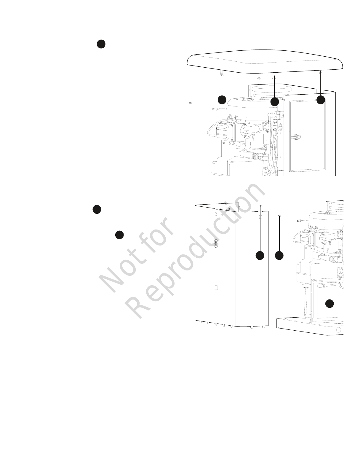
To remove roof:
1. Remove the five screws that secure the roof to
the unit.
2. Carefully lift and remove roof from unit.
A
To remove front panel:
1. Remove the two screws that secure the panel to the
unit.
2. Lift and flex panel outward and off base. Use caution
not to damage the battery box (C.
To secure front panel:
1. Place panel in unit.
2. Secure the panel with two screws.
B
C
A
A
B B
A
14
C
B
Page 15

Not for
Reproduction
System Control Panel
The generator control board, located inside the generator,
under the roof, is shown below. Brief descriptions of the
controls used during installation are:
A
- Menu/Programming Navigation Buttons — See
Menu section for details
B
- Mini USB Port — Authorized Dealer Service Use Only.
C
- Generator Operation Control Buttons —
• “AUTO” Normal operating position. Press and hold
button to put unit into Automatic mode. In Automatic
mode, if a utility power outage is sensed, the system
will start the generator. When utility power is restored,
auto lets the engine stabilize internal temperatures,
shuts o the generator, and waits for the next utility
outage.
• “OFF” Turns o running generator, prevents unit from
starting, and resets any detected service codes.
OFF must be pressed and held for more than 5 seconds in
order to reset service code memory.
•“MANUAL” Used to manually start the generator.
D
– 15 Amp Fuse — Protects the home generator DC
control circuits. If the fuse has ‘blown’ (melted open)
or was removed, the engine cannot crank or start.
Replace the fuse using only an identical ATO 15A fuse.
One spare fuse is supplied with the unit.
E
- Cover — This protective cover must be removed to
access the fuse and the USB port.
F
- Digital Display — Displays generator mode, menu
options, service codes, and service engine indicators
More information may be found in Controls in the
operator’s manual.
F
menu
A
B
auto
C
ok
esc
E
D
off manual
15
Page 16

Not for
Reproduction
Menu
ok
ok
ok
ok
ok
ok
ok
ok
ok
The following chart shows the icons for the buttons that control the system control panel.
ok
MENU
ESCAPE (EXIT)
RIGHT ARROW
LEFT ARROW
MANUAL MODE
OFF
AUTOMATIC MODE
ENTER THE MENU (VIEW SETTINGS)
PRESS TO CONFIRM SELECTION WHEN PROGRAMMING.
RETURN TO LAST MENU ITEM
TOGGLE THROUGH MENU OPTIONS
SETTING SYSTEM PARAMETERS
TOGGLE THROUGH MENU OPTIONS
SETTING SYSTEM PARAMETERS
USED TO MANUALLY START THE GENERATOR. PRESS AND HOLD BUTTON TO START
THE GENERATOR.
TURNS OFF RUNNING GENERATOR, PREVENTS UNIT FROM STARTING, AND RESETS
ANY DETECTED SERVICE CODES.
NORMAL OPERATING POSITION. PRESS AND HOLD BUTTON TO PUT UNIT INTO
AUTOMATIC MODE. IF A UTILITY POWER OUTAGE IS SENSED, THE
SYSTEM WILL START THE GENERATOR. WHEN UTILITY POWER IS RESTORED, AUTO
LETS THE ENGINE STABILIZE INTERNAL TEMPERATURES, SHUTS OFF THE GENERATOR, AND WAITS FOR THE NEXT UTILITY POWER OUTAGE.
The following chart describes key sequences for accessing different programming modes;
ok
16
GENERAL
SET-UP
WIRELESS
LINK MODE
PRESS AND HOLD [ARROW LEFT AND ARROW RIGHT] FOR
THREE SECONDS TO ENTER THE PROGRAM MODE.
PRESS AND HOLD [MENU AND ESC] FOR THREE SECONDS TO
ENTER THE WIRELESS LINKING MODE. (ONLY APPLICABLE ON
CERTAIN MODELS).
Page 17

Not for
Reproduction
General Set Up Screen
ok
ok
For general set up, press and hold the left arrow and right arrow for 3 seconds. Follow the prompts as outlined below.
NOTE: Date and Time were set at the factory and stored in the control panel memory. The Exercise Cycle was also set at
the factory. The default exercise cycle occurs on Tuesdays, at 2:00 P.M. Central Standard Time. To update or change these
settings, follow the steps below.
SET DATE
or
SET TIME
or
YEAR
FLASHING
or or or
HOURS
FLASHING
or or or
or
MONTH
FLASHING
MINUTES
FLASHING
DAY##
FLASHING
AM/PM
FLASHING
If set to OFF, display will read:
EXERCISE CYCLE OFF
or
SET EXERCISE
CYCLE
EVENT LOG
DAY OF WEEK
FLASHING
or or or or
HOURS
FLASHING
MINUTES
FLASHING
Display will scroll last service code event, date, time,
and ambient temperature of when the event occurred.
IF DURING PROGRAMMING NO BUTTONS ARE PRESSED FOR 30 SECONDS,
THE CONTROL PANEL WILL AUTOMATICALLY EXIT THE PROGRAM MODE.
AM/PM
FLASHING
or
17
Page 18

Not for
Reproduction
Control Panel Prompts
Automatic Mode
In Automatic Mode, the display screen will display via
scrolling text:
• GENERATOR READY - if the unit is in standby and utility
power is present.
• GENERATOR ON - if the unit is running and utility
power is not on.
• SERVICE CODE - if a system service code has been
detected.
General System Parameters
To view general system parameters, press the MENU button.
The following will scroll across the digital display and then
move to the next item:
• Run time (total hours the unit has run since installation)
• Date
• Time
• Exercise Cycle date and start time
The user can press the LEFT ARROW or RIGHT ARROW at any
time to move to the next item.
The user can press ESCAPE to go back to GENERATOR READY.
If no user inputs are made for 10 seconds after all the items
have been displayed, the control board will reset to
GENERATOR READY.
AUTOMATIC MODE
GENERATOR READY OR SERVICE CODE DESCRIPTION
(When Generator NOT Running - Auto Mode)
GENERATOR ON
(When Generator Running - Auto Mode)
ok
(MENU)
RUN TIME
or
DATE
or
18
TIME
or
EXERCISE CYCLE
Page 19

Not for
Reproduction
Operation
Important Owner’s Considerations
Engine Oil
The engine is shipped from the factory pre-run and filled
with synthetic oil (API SJ/CF 5W-30). This allows for system
operation in a wide range of temperature and climate
conditions. Before starting the engine, check oil level as
described in Maintenance.
NOTICE Any attempt to crank or start the engine before it has
been properly serviced with the recommended oil will result in
equipment failure.
• Damage to equipment resulting from failure to follow this
instruction will void engine and generator warranty.
Battery
WARNING Battery posts, terminals and related accessories
contain lead and lead compounds, chemicals known to the State
of California to cause cancer and reproductive harm. Wash hands
after handling.
The installer must supply a rechargeable 12 volt DC starting
battery. See Battery in Final Installation Considerations in the
installation manual.
With the battery installed, all wiring to transfer switch and
home generator completed, utility power supplied to the
automatic transfer switch, and the unit in AUTO mode, the
battery receives a trickle charge while the engine is not
running. The trickle charge cannot be used to recharge a
battery that is completely discharged.
NOTICE A battery booster should never be used to quick
charge a low battery.
15 Amp Fuse
The generator’s 15 Amp fuse is critical to correct system
operation. The 15 Amp fuse was removed at the factory.
Your installer will ensure the fuse is properly installed upon
completion of the installation.
19
Page 20

Not for
Reproduction
Automatic Operation
The generator’s control board constantly monitors utility
voltage. Should utility voltage drop below a preset level, the
control board will signal the engine to crank and start.
When utility voltage is restored above a preset voltage level,
the engine is signaled to shut down.
The actual system operation is not adjustable and is
sequenced by sensors and timers on the control board,
as follows:
Utility Voltage Dropout Sensor
• This sensor monitors utility source voltage.
• If utility source voltage drops below about 70 percent
of the nominal supply voltage, the sensor energizes
a 3 second timer. The timer is used to ‘sense’
brown-outs.
• Once the timer has expired, the engine will crank
and start.
Utility Voltage Pickup Sensor
This sensor monitors utility voltage. When utility voltage is
restored above 80 percent of the nominal source voltage,
a time delay starts timing and the engine will go to engine
cool-down.
Engine Cool-down Timer
When utility power is sensed and the load transfers back to
the utility source, the engine will go into a cool down period
as described below:
• If the generator has run for MORE than 5 minutes,
once the utility transfer occurs, the engine will
continue to run for about 1 minute before shutting
down.
• If the generator has run for LESS than 5 minutes, once
the utility transfer occurs, the engine will continue to
run until 5 minutes has elapsed before shutting down.
Setting Exercise Timer
The generator is equipped with an exercise timer. During the
exercise period, the unit runs for approximately 20 minutes
and then shuts down. Electrical load transfer DOES NOT
occur during the exercise cycle (unless an utility power
outage occurs).
The generator will only enter the exercise cycle if the unit
is in the AUTO mode and this exact procedure is followed.
To set the exercise timer:
NOTICE The generator is set with a deservice code exercise
cycle setting of Tuesday at 2:00 P.M, Central Time. To change
the cycle setting, proceed to the following steps:
1. Choose the day and time you want your generator to
exercise.
2. Press and hold the left arrow and right arrow
simultaneously for three seconds to enter the General
Set-Up program mode. See General Set-Up flow chart
in Menu Section.
3. Verify and/or set the time and date on the unit.
4. Go to the SET EXERCISE prompt and hit the “OK”
button.
NOTICE Items will flash until they are selected.
SELECT DAY: Use the left or right arrow to toggle
through the days of the week, Once the day is
selected, hit the “OK” button.
SELECT HOUR: Use the left or right arrow to toggle
through between 1 and 12. Choose the hour of day
you want the generator to exercise then hit the “OK”
button.
SELECT MINUTE: Use the left of right arrow to toggle
between :00 and :59. Choose the minute of the day
you want the generator to exercise then hit the “OK”
button.
SELECT AM/PM: Use the left of right arrow to toggle
between AM and PM. Once chosen, hit the “OK”
button.
NOTICE During the weekly exercise cycle, the generator will
run for 20 minutes, but it will not supply power to the home.
During the exercise cycle, the in-home monitor will continue
blinking the GENERATOR READY green LED.
If you want to change the day and time the unit exercises,
simply perform the procedure again.
To turn off the generator exercise cycle, go to the OFF
selection within the day of the week menu and press OK. The
display will then scroll: EXERCISE CYCLE OFF.
20
Page 21

Not for
Reproduction
Wireless Monitor
DEALER NAME
DEALER
PHONE
generator power
service needed
generator ready
system update
1 low battery voltage
2 low uid level
3 under/over voltage
4 engine does not start
part #: 316196 fcc id: MCQ-XBS2C IC id: 1846A-XBS2C
5 low frequency
6 engine overspeed
7 high temperature
8 transfer switch
# of flashes service needed
The generator is supplied with a battery-powered, wireless
monitor.
The monitor communicates wirelessly with the generator
control panel. The monitor may be placed in a suitable
location in the home. The system has a line-of-sight range of
about 200 feet, but this distance will decrease if the signal
has to pass through walls or other objects.
The wireless monitor communicates with the generator,
every 10 minutes and will display the status via a green or
red LED light on the front of the monitor.
Compare the illustration below with your monitor to
familiarize yourself with these important components.
• Generator Ready (A) - Green LED
• Generator Power (B) - Green LED
• Service Needed (C) - Red LED
• System Update (D) - Press for current system update
with generator.
• Service code descriptions (E) - Name and number
of flashes are listed on the backside of the wireless
monitor.
• Battery Access Cover (F) - Record the dealer name
and phone number on the label provided. Once
removed, two non-rechargeable AA batteries are
installed in the compartment (). .
A
B
C
D
E
F
G
A
B
C
D
E
G
F
21
Page 22

Not for
Reproduction
Wireless Monitor Operation
1 low battery voltage
2 low uid level
3 under/over voltage
5 low frequency
6 engine overspeed
7 high temperature
# of flashes service needed
1 low battery voltage
2 low uid level
3 under/over voltage
4 engine does not start
part #: 316196 fcc id: MCQ-XBS2C IC id: 1846A-XBS2C
5 low frequency
6 engine overspeed
7 high temperature
8 transfer switch
# of flashes service needed
1. Remove battery access cover (A) on back of monitor
A
and install 2 AA batteries. (Observe correct battery
polarity which is embossed in the bottom of the
battery compartment). Replace battery access cover.
vice needed
4 engine does not start
part #: 316196 fcc id: MCQ-XBS2C IC id: 1846A-XBS2C
e
8 transfer switch
4. “LINKING MODE” will scroll across the generator
control panel.
5. Locate and hold the SYSTEM UPDATE button (C) on
C
the wireless monitor for 5 seconds. All 3 LEDs will flash
until the monitor links to the generator. Once it links,
the monitor will display the current state. The monitor
will try to link for 1 minute. (This step can only be
completed when the generator is in Linking Mode).
DEALER NAME
DEALER
PHONE
A
NOTICE The wireless monitor was linked to the generator at
the factory. Communication will begin upon the installation
of the batteries and the generator being placed in AUTO
mode. You may need to press System Update one time.
2. The wireless monitor does not have an on/off
switch. When batteries are installed correctly,
the GENERATOR READY green LED light will flash
once every 10 seconds indicating the status of the
generator.
NOTICE If communication does not begin upon placing the
generator in AUTO, installing batteries, and pressing System
Update, the monitor may need to be re-linked. To link, follow
Steps 3 through 6.
3. Locate the MENU AND ESCAPE buttons on the control
panel (B) . Press and hold for 3 seconds to enter the
B
linking mode.
generator ready
generator power
service needed
C
system update
6. Once the link has been confirmed, press the OK
button on the generator control panel to exit or the
control board will turn off linking after 5 minutes. The
generator will now communicate with the wireless
monitor.
NOTICE It may take up to 1 minute for the monitor to begin
displaying the generator status correctly.
menu
ok
esc
off manual
B
B
auto
22
Page 23

Not for
Reproduction
Standard Operation:
Wireless Monitor Status LED’s
• The wireless monitor receives data from the generator
every 10 minutes and displays the generator status
through 3 LED’s.
• Pressing the SYSTEM UPDATE button will provide
current generator status by flashing the status LED’s.
When pressed, all 3 LEDs will flash until the generator
status is received.
NOTICE Generator control panel must be in AUTO mode or
no communication with monitor will occur.
• In order to conserve power and to extend battery life,
the LED’s are not lit continuously; instead they are
briefly flashed as indicated below.
NOTICE During the weekly exercise cycle, the generator will
run for 20 minutes, but it will not supply power to the home.
During the exercise cycle, the monitor will continue blinking
the GENERATOR READY green LED.
• GENERATOR READY - When active, the green LED will
flash once every 7 seconds. The green LED indicates
that the generator is in AUTO mode and that it is
ready to run in the event of a loss of utility power.
• GENERATOR POWER - When active, the green LED will
flash every 7 seconds. The green LED indicates that
the generator is supplying power.
• SERVICE NEEDED - When active, the red LED will flash
in a sequence that corresponds to the service code.
For example, when Low Frequency scrolls across the
control board, the red LED will flash 5 times with a 3
second pause between series of blinks until it is reset
or the condition is corrected. When the red LED is lit,
contact your nearest authorized service dealer.
NOTICE None of the conditions on the display unit can be
cleared at the wireless monitor. All alerts must be cleared at
the generator control panel.
NOTICE Service conditions will only be displayed on the
basic monitor when the control board is placed in AUTO
mode.
Other:
LED Lighting Codes
• Batteries Inserted - GENERATOR READY LED will light
for 5 seconds.
• Wireless Communication Lost - SERVICE NEEDED LED
will flash 20 fast pulses, then pause for 5 seconds,
and repeat the sequence until the communication
has been restored.
• Linking Error or Not Linked - SERVICE NEEDED LED will
light for 4 seconds, pause for 4 seconds, and repeat
the sequence until a successful link is completed.
23
Page 24

Not for
Reproduction
Maintenance
Servicing the System
Before performing any generator maintenance, always
perform the following steps:
1. Set generator’s circuit breaker to its OFF position.
2. Press and hold the control board OFF button.
3. Remove 15 Amp fuse from control board.
Service Code Detection System
The generator may have to run for long periods of time
with no operator present. For that reason, the system is
equipped with sensors that automatically shut down the
generator in the event of potentially damaging conditions,
such as low oil pressure, high temperature, over speed, and
other conditions.
The generator’s control board shows service code
descriptions scrolling across the digital display. The service
code descriptions are listed below:
• Low Battery Voltage
• Low Oil Pressure
• Under Voltage
• Over Voltage
• Engine Does Not Start
• Low Frequency
• Engine Overspeed
• High Oil Temperature
• Transfer Switch Service code
• No Wireless Communication
• Battery Charge Circuit
4. Utility voltage is present at generator control board.
Disconnect power before servicing control board by
removing the fuses from the transfer switch.
5. After all servicing has been completed, replace fuses
in transfer switch, replace 15 Amp fuse in control
board, set circuit breaker ON and press and hold
control board AUTO button.
Reset Service code Detection System
The operator must reset the service code detection system
each time it activates. To do so, press the control board OFF
button for 5 seconds. Once the display turns off, leave it off
for at least 30 seconds. Remedy the service code condition,
then return the home generator to service by pressing and
holding the control board AUTO button and installing the 15
Amp fuse (if removed).
Low Battery Voltage
This service code is indicated by Low Battery Voltage scrolling
across the digital display and a single flash on the wireless
monitor. This condition occurs if the battery voltage drops
below the preset value. Causes for this problem may be a
service code battery or battery charge circuit. See Battery
Charge Circuit,
Remove the 15 Amp fuse and disconnect the battery from
the generator. Test the battery voltage. If voltage meets
specifications, take the battery to a local battery store for
analysis. Or contact your local service center for assistance.
Reinstall the battery (replace if necessary - see Battery in
Final Installation Considerations in the installation manual).
Then reset the service code detection system, as described
earlier.
24
Page 25

Not for
Reproduction
Low Oil Pressure
This service code is indicated by Low Oil Pressure scrolling
across the digital display and two flashes on the wireless
monitor. The unit is equipped with an oil pressure switch
that uses normally closed contacts held open by engine oil
pressure during operation. Should oil pressure drop below
the 8 psi range, switch contacts close and the engine will
shut down.
To remedy the low oil pressure condition, add the
recommended oil to the FULL mark on the dipstick.
If the low oil pressure condition still exists, the engine will
start, then shut down again. The service code will appear. In
this case, contact an authorized dealer.
Under Voltage
This service code is indicated by Under Voltage scrolling
across the digital display and three flashes on the wireless
monitor. This condition is caused by a restriction in the
fuel flow, the electronic governing system not functioning
properly, a broken or disconnected signal lead, a failed
alternator winding, the control board circuit breaker is open,
or the generator is overloaded.
To remedy the problem, contact your installer or an
authorized dealer.
Over Voltage
This service code is indicated by Over Voltage scrolling across
the digital display and three flashes on the wireless monitor.
This feature protects devices connected to the transfer
switch by shutting the generator down if the generator
output voltage happens to increase above the preset limit.
This condition is most likely caused by a failed voltage
regulator, alternator excitation circuit or a load imbalance. To
remedy the problem, contact your installer or an
authorized dealer.
Engine Does Not Start
This service code is indicated by Engine Does Not Start
scrolling across the digital display and four flashes on the
wireless monitor. This feature prevents the generator from
damaging itself if it continually attempts to start in spite
of another problem, such as no fuel supply. Each time the
system is directed to start, the unit will crank for 10 seconds,
pause for 10 seconds, and repeat. If the system does not
begin producing electricity after approximately 2 minutes,
the unit will stop cranking.
The most likely cause of this problem is no fuel supply or
incorrect fuel selector setting. See Fuel Selection Switch in
the installation manual. Check the internal and external fuel
shut off valves to ensure they are fully open. Other causes
could be failed spark plug(s), a loose electronic governor
connection, a failed engine ignition, or the engine air filter
is clogged. You may need to contact your installer for
assistance if you can’t remedy these problems.
Low Frequency
This service code is indicated by Low Frequency scrolling
across the digital display and five flashes on the wireless
monitor. This feature protects devices connected to the
transfer switch by shutting the generator down if the engine
runs slower than 55 Hz for three seconds. This condition is
caused by a failed engine component, electronic governor
system, or by excessive loads on the generator. To resolve
the problem, contact your installer or an authorized dealer.
Engine Overspeed
This service code is indicated by Engine Overspeed scrolling
across the digital display and six flashes on the wireless
monitor. This condition can be caused by a problem within
the electronic governor system.
To resolve the problem, contact your installer or an
authorized dealer.
High Oil Temperature
This service code is indicated by High Oil Temperature
scrolling across the digital display and seven flashes on the
wireless monitor. The contacts of the temperature switch
are normally open. If the engine temperature exceeds a
predetermined temperature, the service code is detected and
the engine shuts down.
Common causes for this condition include running the
unit with an access doors removed, obstructed air inlet
or exhaust port, or debris in the engine compartment or
running unit with roof open.
To resolve the problem, let the engine cool down and remove
any accumulated debris and obstructions. Ensure that the
access doors are installed and the roof is closed whenever
the unit is running. If problem persists, contact your installer
or an authorized dealer.
Transfer Switch Service code
This service code is indicated by Transfer Switch Service
code scrolling across the digital display (if transfer switch is
equipped with service code detection) and eight flashes on
the wireless monitor.
The most likely cause of this service code is a blown fuse in
the transfer switch. To remedy the problem, contact your
installer or an authorized dealer.
No Wireless Communication
This service code is indicated by No Monitor Communication
scrolling across the digital display. The SERVICE NEEDED red
LED on the wireless monitor will flash 20 fast pulses, pause
5 seconds, and repeat if there is a loss in communication
between the wireless monitor and the generator.
To resolve the problem, move the wireless monitor closer to
generator. Re-link if necessary.
Battery Charge Circuit
This service code is indicated by Battery Charge Circuit
scrolling across the digital display. The most likely cause is
an electrical problem with the control panel. To remedy the
problem, contact your installer or an authorized dealer.
25
Page 26

Not for
Reproduction
Maintenance Schedule
Follow the hourly or calendar intervals of operation,
whichever occurs first.
First 5 Hours
Change Engine Oil
Every 8 Hours or Daily
Clean Debris
Check Engine Oil Level
Every 100 Hours or Annually
Change Air Filter
Change Engine Oil and Filter
Replace Spark Plugs
Check Valve Clearance
Check Circuit Breaker Torques
Annually
Clean Oil Cooler Fins
Regular maintenance will improve the performance and
extend the life of the generator. See any authorized dealer
for service.
Emissions Control
Maintenance, replacement, or repair of the emissions
control devices and systems may be performed by any
non-road engine repair establishment or individual.
However, to obtain ”no charge” emissions control service, the
work must be performed by a factory authorized dealer. See
the Emissions Warranty.
Generator Maintenance
The generator’s warranty does not cover items that have
been subjected to operator abuse or negligence. To receive
full value from the warranty, the operator must maintain the
generator as instructed in this manual.
Some adjustments will need to be made periodically to
properly maintain your generator.
All service and adjustments should be made at least once
each season. Follow the requirements in the Maintenance
Schedule chart.
Generator maintenance consists of keeping the unit
clean. Operate the unit in an environment where it will
not be exposed to excessive dust, dirt, moisture or any
corrosive vapors. Cooling air louvers on the enclosure
must not become clogged with snow, leaves, or any other
foreign material. To prevent generator damage caused by
overheating, keep the enclosure cooling inlets and outlets
clean and unobstructed at all times.
Check the cleanliness of the unit frequently and clean when
dust, dirt, oil, moisture or other foreign substances are visible
on its exterior/interior surface. Inspect the air inlet and outlet
openings inside and outside the enclosure to ensure air flow
is not blocked.
DO NOT use direct spray from a garden hose to clean
generator. Water can enter the engine and generator and
cause problems.
26
NOTICE Improper treatment of generator could damage it and
shorten its life.
• DO NOT expose generator to excessive moisture, dust, dirt, or
corrosive vapors.
• DO NOT insert any objects through cooling slots.
Clean the generator as follows:
1. Press and hold the control board OFF button.
2. Remove 15 Amp fuse from control board.
3. Clean generator as desired.
• Use a damp cloth to wipe exterior surfaces clean.
• Use a soft, bristle brush to loosen caked on dirt, etc.
• Use a vacuum cleaner to pick up loose dirt and debris.
• Use low pressure air (not to exceed 25 psi) to blow
away dirt. Inspect cooling air slots and openings on
the generator. These openings must be kept clean
and unobstructed.
4. Reinstall 15 Amp fuse in control board.
5. Press and hold the control board AUTO button.
Page 27

Not for
Reproduction
Battery
Servicing of batteries is to be performed or supervised
by personnel knowledgeable of batteries and the
required precautions. Keep unauthorized personnel away
from batteries.
Servicing the Battery
If it is necessary to service the battery, proceed as follows:
1. Press and hold the control board OFF button.
2. Remove 15 Amp fuse from control panel.
3. Service or replace battery as required. See Battery
in Final Installation Considerations in the installation
manual for specific battery needed.
4. Connect red battery cable to battery positive terminal
(indicated by POSITIVE, POS, or (+)).
Charging the Battery
If it is necessary to charge the battery, proceed as follows:
1. Press and hold the control board OFF button.
2. Remove 15 Amp fuse from control board.
3. Disconnect negative battery cable from negative
battery terminal (indicated by NEGATIVE, NEG, or (-)).
NOTICE Failure to disconnect negative battery cable could result in
equipment failure.
• DO NOT attempt to jump start the generator.
• Damage to equipment resulting from failure to follow this
instruction will void engine and generator warranty.
WARNING Battery posts, terminals and related accessories
contain lead and lead compounds, chemicals known to the State
of California to cause cancer and reproductive harm. Wash hands
after handling.
6. Connect black negative battery cable to negative
battery terminal (indicated by NEGATIVE, NEG, or (-).
7. Ensure hardware on both positive and negative
battery terminals is secure.
8. Reinstall 15 Amp fuse in control panel.
9. Press and hold the control board AUTO button.
DON’T POLLUTE. CONSERVE RESOURCES, RETURN
USED BATTERY TO RECYCLING COLLECTION CENTER.
4. Charge battery with battery charger at 2 Amps until
battery holds 12 Volts. DO NOT exceed 13.7 volts
when charging.
NOTICE DO NOT use a battery booster to quick charge a low
battery.
5. Connect negative battery cable to negative battery
terminal (indicated by NEGATIVE, NEG, or (-)).
6. Ensure hardware on both positive and negative
battery terminals is secure.
7. Reinstall 15 Amp fuse in control board.
8. Press and hold the control board AUTO button.
WARNING Storage batteries give off explosive hydrogen gas
during recharging.
Slightest spark will ignite hydrogen and
cause explosion, resulting in death or
serious injury.
Battery electrolyte fluid contains acid and is extremely caustic.
Contact with battery contents could cause severe chemical burns.
A battery presents a risk of electrical shock and high short
circuit current.
• DO NOT dispose of battery in a fire. Recycle battery.
• DO NOT allow any open flame, spark, heat, or lit cigarette during
and for several minutes after charging a battery.
• DO NOT open or mutilate the battery.
• Wear protective goggles, rubber apron, rubber boots and
rubber gloves.
• Remove watches, rings, or other metal objects.
• Use tools having insulated handles.
CAUTION With the system switch set to AUTO, the engine could
crank and start at any time without warning, resulting in
minor or moderate injury.
• To prevent possible injury that could be caused by such sudden
starts, always set the system switch to OFF if performing
maintenance on the system.
• Remove the 15 Amp fuse before working on or around the
generator or transfer switch.
27
Page 28

Not for
Reproduction
Engine Maintenance
WARNING Unintentional sparking could cause fire or electric
shock resulting in death or serious injury.
WHEN ADJUSTING OR MAKING REPAIRS TO YOUR GENERATOR
• Disconnect the spark plug wire from the spark plug and place the
wire where it cannot contact spark plug.
WHEN TESTING FOR ENGINE SPARK
• Use approved spark plug tester.
• DO NOT check for spark with spark plug removed.
Adjust Valve Lash
The valve lash must be checked every 100 hours of
operation. Measure valve clearance with the engine cold.
To adjust the valve lash, proceed as follows:
1. Remove spark plug(s) to ease manual rotation of
engine crankshaft.
2. Turn crankshaft counterclockwise until the piston is at
Top Dead Center on the compression stroke.
3. Insert a narrow screwdriver or rod into spark
plug hole as a gauge, then slowly turn crankshaft
counterclockwise until the piston has moved down
the bore by 1/4”.
4. For the Model 31 Engine:
• Use a feeler gauge (A) , measure the valve
clearance.
• Adjust the rocker nut to obtain the correct
clearance as follows: 0.005 (0.013 mm) intake
and 0.007 (0.018 mm) exhaust.
• Hold rocker nut and tighten the rocker ball set
screw (B) to 45 in/lb (5 Nm).
5. For the Model 35 Engine:
• Use a feeler gauge (A) to measure the valve
clearance.
• Adjust the clearance by loosening the lock nut
(B) then turn the adjusting screw (C) to obtain
B C
the following measurement: 0.005 in. (0.013 mm)
intake and exhaust.
• Once the clearance is properly set, hold the
adjusting screw while torquing the lock nut to 70
in/lbs. (8 Nm).
6. Repeat for the other valve, if applicable.
B
A
A
When all engine servicing is complete, replace 15 Amp fuse
in control board and reset exercise timer.
A
B
Model 31 Engine
B
C
28
Model 35 Engine
Page 29

Not for
Reproduction
Engine Oil
The engine is filled with synthetic oil (API SJ/CF 5W-30).
This allows for system operation in the widest range of
temperature and climate conditions.
We recommend the use of Briggs & Stratton Warranty
Certified oils for best performance. Other high-quality
detergent oils are acceptable if classified for service SJ or
higher. DO NOT use special additives.
Outdoor temperatures determine the proper oil viscosity for
the engine. Use the chart to select the best viscosity for the
outdoor temperature range expected.
NOTICE Synthetic oil meeting ILSAC GF-2, API
certification mark and API service symbol with “SJ/
CF ENERGY CONSERVING” or higher, is an acceptable
oil at all temperatures. Use of synthetic oil does not
alter required oil change intervals.
Changing Engine Oil and Oil Filter
Open roof and remove front panel to access the oil filter and
to add engine oil.
* Below 40°F (4°C) the use of SAE 30 will result in hard
starting.
** Above 80°F (27°C) the use of 10W30 may cause increased
oil consumption. Check oil level more frequently.
Checking/Adding Engine Oil
1. Open roof to access dipstick and oil fill area.
2. Clean the oil fill area of any debris.
3. Remove the dipstick and wipe with a clean cloth.
4. Fully insert dipstick into oil fill.
5. Remove dipstick and check oil level. Verify oil is at Full
mark on dipstick.
6. If needed, slowly pour recommended oil into oil fill
opening. DO NOT overfill. After adding oil, wait one
minute and recheck oil level.
NOTICE Overfilling with oil could cause the engine to not start, or
hard starting.
• DO NOT overfill.
• If over the FULL mark on dipstick, drain oil to reduce oil level to
FULL mark on dipstick.
7. Replace oil dipstick.
8. Close roof and secure.
29
Page 30

Not for
Reproduction
Changing Engine Oil and Oil Filter
CAUTION Avoid prolonged or repeated skin contact with used
motor oil.
• Used motor oil has been shown to cause skin cancer in certain
laboratory animals.
• Thoroughly wash exposed areas with soap and water.
KEEP OUT OF REACH OF CHILDREN. DON’T POLLUTE.
CONSERVE RESOURCES. RETURN USED OIL TO
COLLECTION CENTERS.
NOTICE Any attempt to crank or start the engine before it has
been properly serviced with the recommended oil will result in
equipment failure.
• DO NOT attempt to crank or start the engine before it has been
properly serviced with the recommended oil. This may result in
an engine failure.
• Damage to equipment resulting from failure to follow this
instruction will void engine and generator warranty.
Change the oil while the engine is still warm from running, as
follows:
1. Press and hold the control board OFF button.
2. Remove 15 Amp fuse from control board.
3. Place oil drain hose into an approved container.
4. Remove brass fitting from end of drain hose and drain
oil into an approved container.
5. When oil has drained, replace brass fitting on hose.
6. Place oil absorbing towels under oil filter.
7. Remove oil filter and dispose of properly.
8. Before installing a new oil filter, lightly lubricate the oil
filter gasket with fresh, clean oil.
9. Install the oil filter by hand until the gasket contacts
the oil filter adapter, then tighten the oil filter 1/2 to
3/4 turn.
10. Add oil.
11. Remove container from under oil filter and clean up
any spilled oil.
12. Start and run engine. As engine warms up, check for
oil leaks.
13. Stop engine, wait for oil to settle, check oil level and
add if necessary.
Service Air Cleaner
Your engine will not run properly and may be damaged if you
run it with a dirty air cleaner. Clean or replace more often if
operating under dusty or dirty conditions.
To service the air cleaner, follow these steps:
1. Remove the knobs and the cover.
2. Remove air filter.
3. To loosen debris, gently tap air cleaner on a hard
surface. If air cleaner is excessively dirty, replace with
a new air cleaner.
4. Install the air filter.
5. Install the cover and secure with knobs.
NOTICE
same position as the original parts.
Replacement parts must be the same and installed in the
30
Page 31

Not for
Reproduction
Fuel System Inspection and Maintenance
Natural Gas / Propane Fuel System
The fuel system installed on this industrial engine has been
designed to various standards to ensure performance and
reliability. To ensure compliance to these standards, follow the
recommended maintenance schedule contained in this section.
Pressure Regulator Maintenance and Inspection
If the regulator fails to operate or develops a leak, it should be
repaired or replaced with the OEM recommended replacement
parts.
Venturi / Throttle Control Device Maintenance and
Inspection
NOTICE The venturi and throttle body components have been
specifically designed and calibrated to meet the fuel system
requirements of the engine.
NOTICE A dirty air cleaner may significantly alter the venturi
performance.
When inspecting the venturi and throttle body, check for the
following items:
• Leaks at all fittings.
• Ensure the venturi and throttle body are securely
mounted.
NOTICE The fuel system components have been specifically
designed and calibrated to meet the fuel system
requirements of the engine. If a fuel system component
fails to operate or develops a leak, it should be repaired or
replaced with the OEM recommended replacement parts.
When inspecting the regulator, check for the following items:
• Check for any fuel leaks at the inlet and outlet fittings.
• Check for any fuel leaks in the regulator body.
• Check to ensure the regulator is securely mounted
and the mounting bolts are tight.
• Check the regulator for external damage.
• Inspect air cleaner element according to the
recommended maintenance schedule found in this
section.
• Check fuel lines for cracking, splitting, or chaffing,
Replace if any of these conditions exist.
• Check for leaks at the throttle body and intake
manifold.
Exhaust System Maintenance and Inspection
When inspecting the exhaust system, check for the following
items:
• Inspect exhaust manifold at the cylinder head for leaks
and that all retaining bolts and shields (if used) are in
place.
• Inspect manifold to exhaust pipe fasteners to ensure
they are tight and that there are not exhaust leaks.
Repair as necessary.
Engine Exterior
Periodically inspect the engine exterior for contamination
and potential damage from dirt, leaves, rodents, spider webs,
insects, etc. and remove.
• Inspect exhaust pipe connection for leaks. Repair as
necessary.
31
Page 32

Not for
Reproduction
Service Spark Plugs
Changing the spark plugs will help your engine to start easier
and run better.
1. Clean area around spark plugs.
2. Remove and inspect spark plugs.
3. Check electrode gap with wire feeler gauge and reset
spark plug gap to recommended gap if necessary
(see Specifications).
4. Replace spark plugs if electrodes are pitted, burned
or porcelain is cracked. Use the recommended
replacement spark plugs. See Specifications.
5. Install spark plugs and tighten to 180 in/lbs (20 Nm).
Clean Air Cooling System and Oil Cooler Fins
Over time debris may accumulate in cylinder cooling fins
and cannot be observed without partial engine disassembly.
Unobstructed air flow is critical for correct generator
operation. For this reason, we recommend you have an
authorized service dealer clean the cooling system per
recommended intervals (see Maintenance Schedule in the
Maintenance section). Equally important is to keep top of
engine free from debris. Make sure the oil cooler fins are free
of dirt and debris. Also see Cleaning.
When Calling for Assistance
You must have the following information at hand if it is
necessary to contact a local service center regarding
service or repair of this unit:
1. Obtain the unit Model Number and Serial Number
from the unit ID label. See Controls for location of
the label or refer to the information recorded on the
inside front cover of the installation manual.
2. Obtain the engine identification numbers from the
engine label. See Controls for location of the label or
refer to the information recorded on the inside front
cover of the installation manual.
Storage
The home generator system is designed for long term service
as a backup generator. There is no need to take any storage
precautions. However, if it becomes necessary to take the
system out of service for an extended period, call Technical
Services at 888 575-8226, between 8:00 AM and 5:00 PM CT
for specific recommendations.
32
Page 33

Not for
Reproduction
PAGE INTENTIONALLY LEFT BLANK
33
Page 34

Not for
Reproduction
Troubleshooting
Problem Cause Correction
Eng ine is running, but no AC output is available.
Eng ine runs well at no-load but “bogs down” when
loads are connected.
Eng ine will not start; or starts and runs rough.
Engine shuts down during operation.
1. Circuit breaker open or defective.
2. Service code in generator control board.
3. Poor wiring connections or defective transfer
switch.
1. Generator is overloaded.
2. Short circuit in a connected load.
3. Shorted generator circuit.
4. Fuel pressure or mixture is incorrect.
5. Kinked fuel line between regulator and engine.
1. 15 Amp fuse missing or blown.
2. Thermal fuse(s) blown.
3. Fuel supply turned off or depleted.
4. Incorrect fuel selection.
5. Failed battery.
6. Clogged air filter.
1. Fuel supply turned off or depleted.
2. Control board digital display shows a service
code.
1. Reset or replace circuit breaker.
2. Contact local service facility.
3. Check and repair or contact local service
1. Remove one or more loads.
2. Disconnect shorted electrical load.
3. Contact local service facility.
4. See Gaseous Fuel System in the installation
5. Remove kink. Replace if necessary.
1. Install (new) 15 Amp fuse. See System
2. Replace thermal fuse(s).
3. Open fuel valve(s); check propane tank.
4. Check fuel selector switch and set to
5. Replace battery.
6. Clean or replace air filter.
1. Check fuel valves, fill propane tank.
2. Refer to Service code Detection System.
facility.
manual.
Control Board
proper setting. (If applicable)
Loss of power on circuits.
Unit will not exercise.
Excessive Vibration
Odor of fuel
Utility power returns, unit does not stop
1. Generator circuit breaker is open.
2. Transfer switch problems.
1. Control board not set to AUTO.
2. Exercise timer not set or set to OFF.
3. Unit date and time not set.
4. Failed battery.
5. 15 Amp fuse missing or blown.
1. Loose mechanical fastener. 1. Check and repair or contact local service
1. Fuel leak. 1. Turn off manual shutoff fuel valve. Contact
1. Blown fuses in transfer switch.
2. 5 minute minimum runtime not lapsed.
3. Poor wire connection or defective controllers.
1. Reset circuit breaker.
2. See transfer switch manual.
1. Press AUTO button on control board.
2. Set exercise timer.
3. Set unit date and time.
4. Replace battery.
5. Install (new) 15 Amp fuse. See System
Control Board.
facility.
local service facility.
1. Install (new) fuses.
2. Wait 5 minutes.
3. Check, repair or contact local service facility.
34
Page 35

Not for
Reproduction
Wireless Monitor Troubleshooting
Problem Cause Correction
Monitor not flashing status LED’s
Linking error
Wireless communication lost
Service Needed red LED flashing
1. Batteries inserted incorrectly
2. Low battery power
3. Conditions too bright to see flashes
4. Communication from generator is
within 10 minute update sequence
5. Immersed in liquid
6. Monitor not linked.
1. Generator control board not in
“Linking Mode”
2. Monitor “System Update” button
not pressed for 5 seconds during
generator control board “Linking
Mode”
1. Monitor is too far from generator
2. Building materials are blocking
wireless signal (i.e. - steel studs,
aluminum siding, radiant barrier foil
insulation)
1. Generator system needs service
2. Wireless communication lost
3. Linking error
1. Verify correct battery orientation
2. Replace batteries
3. Move monitor to a less lit area
4. Press “System Update” button
5. Allow to dry for 24 hours, replace
batteries. If problem persists
order GE Wireless Monitor (part
number 316196GS)
6. Follow linking procedure.
1. On generator control board
press and hold the MENU and
ESCAPE buttons for 3 seconds
until “Linking Mode” scrolls across
screen. Press and hold “System
Update” button on Monitor for 5
seconds.
2. Press and hold “System Update”
button on Monitor for 5 seconds.
1. Move monitor closer to generator
2. Order Symphony Wireless router
(model 6220) to increase signal
strength
1. Refer to Service code Detection
System in manual
2. See Correction section for
“Wireless communication lost” in
Troubleshooting Guide
3. See Correction section for “Linking
error” in Troubleshooting Guide
35
Page 36

Not for
Reproduction
U.S. EPA, and Briggs & Stratton Corporation Emissions Control Warranty Statement for Emergency Standby Engines
Your Warranty Rights And Obligations
January 2014
General Information
The U.S. EPA, and Briggs & Stratton (B&S) are pleased to explain the
emissions control system warranty on your Model Year 2014 - 2015
engine / equipment. In the U.S., new Emergency Standby Engines
must be designed, built, and equipped to meet stringent emission
standards. Engines less than 25 Hp must meet requirements of 40
CFR Part 1054. Engines greater than 25 Hp and less than 130 Hp
must meet requirements of 40 CFR Part 1048. B&S must warrant the
emissions control system on your engine / equipment.
See Denition of appropriate use of Emergency Standby below.
The emission-related warranty covers all components whose failure
would increase an engine’s non-evaporative emissions of any
regulated pollutant referenced below.
Manufacturer’s Warranty Coverage:
Briggs & Stratton warrants that the engine is free from defects in
material and workmanship, and is also designed, built, and equipped
to conform to applicable regulations under Section 213 of the Clean
Air Act, from the time the engine is sold, until the expiration of its
warranty period.
This warranty applies to all emission related engine components
whose failure would cause engine exhaust emissions to be out of
EPA compliance. Further, this warranty also applies to other engine
components damaged due to the failure of any of these emissions
related components.
If a warrantable emissions related component on your engine is
defective, the part will be repaired or replaced by B&S at no cost to
you including diagnosis, parts, and labor.
Warranty coverage period is ve years from date of original purchase,
and is oered to the original purchaser and each subsequent
purchaser so long as Owner’s Warranty Responsibilities are adhered
to.
Owner’s Warranty Responsibilities:
• Warranty claims shall be led according to the provisions of the
Briggs & Stratton Warranty Policy.
• An engine may not be warrantable if subjected to abuse, misuse,
neglect, improper maintenance, unapproved modications,
accidents not caused by Briggs & Stratton engines or equipment,
or by acts of God.
• Only those engines used as an Emergency Stationary Engine, as
dened below, are warrantable.
• You are responsible for presenting your engine / equipment to a
B&S distribution center, servicing dealer, or other equivalent entity,
as applicable, as soon as a problem exists. The warranty repairs
should be completed in a reasonable amount of time, not to
exceed 30 days. If you have any questions regarding your warranty
rights and responsibilities, you should contact B&S at 1-800-2333723 or BRIGGSandSTRATTON.COM.
• If any components not scheduled for maintenance is repaired or
replaced under this warranty, the new part will be warranted only
for the remaining warranty period.
• If a warrantable component scheduled for maintenance fails
prior to its rst scheduled replacement, the part will be repaired
or replaced by B&S at no charge to the owner. Any such
component is only warrantable until the originally scheduled
maintenance period has expired.
• Add on or modied parts that are not exempted by the EPA may
not be used. The use of any non-exempted add on or modied
parts by the owner will be grounds for disallowing a warranty
claim. The manufacturer will not be liable to warrant failures or
warranted parts caused by the use of a non-exempted add on or
modied part.
Emergency Stationary Engine Definition
An Emergency Stationary Engine is dened as any stationary internal combustion engine whose operation is limited to emergency situations and
required testing and maintenance. Examples include stationary engines used to produce power for critical networks or equipment (including
power supplied to portions of a facility) when electric power from the local utility (or the normal power source, if the facility runs on its own power
production) is interrupted, or stationary engines used to pump water in the case of re or ood, etc. Stationary engines used for peak shaving
are not considered emergency stationary engines. Stationary engines used to supply power to an electric grid or that supply power as part of
a nancial arrangement with another entity are not considered to be emergency engines. Emergency stationary ICE may be operated for the
purpose of maintenance checks and readiness testing, provided that the tests are recommended by Federal, State or local government, the
manufacturer, the vendor, or the insurance company associated with the engine. Maintenance checks and readiness testing of such units is
limited to 100 hours per year. There is no time limit on the use of emergency stationary engines in emergency situations. The owner or operator
may petition the Administrator for approval of additional hours to be used for maintenance checks and readiness testing, but a petition is
not required if the owner or operator maintains records indicating that Federal, State, or local standards require maintenance and testing of
emergency ICE beyond 100 hours per year. Emergency stationary ICE may operate up to 50 hours per year in non-emergency situations, but
those 50 hours are counted towards the 100 hours per year provided for maintenance and testing. The 50 hours per year for non-emergency
situations cannot be used for peak shaving or to generate income for a facility to supply power to an electric grid or otherwise supply power
as part of a nancial arrangement with another entity. For owners and operators of emergency engines, any operation other than emergency
operation, maintenance and testing, and operation in non-emergency situations for 50 hours per year, as permitted above is prohibited.
80009061 Rev. -
36
Page 37

Not for
Reproduction
Limited Warranty
Coverage
Briggs & Stratton Power Products Group, LLC will repair or replace, free
of charge, any part(s) of the equipment that is defective in material or
workmanship or both. This warranty is effective for the time periods
and subject to the conditions stated below. For all warranty service,
find the nearest Authorized Service Dealer in our dealer locator map at
BRIGGSandSTRATTON.COM.
THERE IS NO OTHER EXPRESS WARRANTY. WARRANTY COVERAGE FOR IMPLIED
WARRANTIES, INCLUDING THOSE OF MERCHANTABILITY AND FITNESS FOR A
PARTICULAR PURPOSE, ARE LIMITED TO THE WARRANTY PERIOD SET FORTH
BELOW, OR TO THE EXTENT PERMITTED BY LAW. LIABILITY FOR INCIDENTAL
OR CONSEQUENTIAL DAMAGES ARE EXCLUDED TO THE EXTENT PERMITTED BY
LAW.
*
Warranty Period
PARTS 4 years †
LABOR 4 years †
TRAVEL 4 years † ‡
Some states or countries do not allow limitations on how long an implied
warranty lasts, and some states or countries do not allow the exclusion or
limitation of incidental or consequential damages, so the above limitation
and/or the above exclusion may not apply to you. This warranty gives you
specific legal rights and you may also have other rights which vary from state
to state or country to country.*
In Australia - Our goods come with guarantees that cannot be excluded
*
under the Australian Consumer Law. You are entitled to a replacement or
refund for a major failure and for compensation for any other reasonably
foreseeable loss or damage. You are also entitled to have the goods repaired
or replaced if the goods fail to be of acceptable quality and the failure
does not amount to a major failure. For warranty service, find the nearest
Authorized Service Dealer in our dealer locator map at BRIGGSandSTRATTON.
COM, or by calling 1300 274 447, or by emailing or writing to salesenquires@
briggsandstratton.com.au, Briggs & Stratton Australia Pty Ltd, 1 Moorebank
Avenue, NSW, Australia, 2170.
† Enclosure is warranted against surface rust and corrosion for the first year
of the warranty period. Surface rust and corrosion is defined as any rust
or corrosion that has penetrated the paint but has not penetrated through
the metal substructure.
Enclosure is warranted against rust-through for the first two years of the
warranty period. Rust-through is defined as rust or corrosion that has
penetrated completely through the paint and metal substructure.
† Accessory parts have a separate warranty. Refer to the warranty included
with the accessory part at purchase.
‡ Travel expenses are reimbursed as specified under the Briggs & Stratton
Warranty Guidelines document to authorized Briggs & Stratton dealers for
performing applicable warranty repair work.
is a trademark of General Electric Company
and is under license by Briggs & Stratton
Power Products Group, LLC.
The warranty period begins on the date of purchase by the first retail or
commercial customer. In order to ensure prompt and complete warranty
coverage, REGISTER YOUR PRODUCT IN ONE OF THREE WAYS:
1. ONLINE AT BRIGGSANDSTRATTON.COM, OR
2. MAIL THE COMPLETED REGISTRATION CARD, OR
3. CALL 888-575-8226
SAVE YOUR PROOF OF PURCHASE RECEIPT. IF YOU DO NOT PROVIDE PROOF
OF THE INITIAL PURCHASE DATE AT THE TIME WARRANTY SERVICE IS
REQUESTED, THE MANUFACTURING DATE OF THE PRODUCT WILL BE USED TO
DETERMINE THE WARRANTY PERIOD.
Registration is not required to obtain warranty service.
Warranty terms continue on next page.
Copyright © 2013. All rights reserved. No part of this material may
be reproduced or transmitted in any form without the express
written permission of Briggs & Stratton Power Products Group, LLC.
37
Page 38

Not for
Reproduction
About Your Warranty
Only authorized service dealers may perform warranty repairs. Most
warranty repairs are handled routinely, but sometimes requests for
warranty service may not be appropriate. For example, warranty
service would not apply if equipment damage occurred because
of misuse, lack of routine maintenance, and shipping, handling,
warehousing or improper installation. Similarly, warranty coverage
will not be provided if the manufacturing date or serial number(s)
on the equipment has been removed or the equipment has been
altered or modified. During the warranty period, the authorized
service dealer, at its option, will repair or replace any part that, upon
examination, is found to be defective under normal use and service.
This warranty will not cover the following repairs due to:
1. Normal Wear and Maintenance: Outdoor Power Equipment and
engines, like all mechanical devices, need periodic parts and service
to perform well. This warranty does not cover repair when normal
use has exhausted the life of a part or the equipment. Typical wear
items include engine oil, oil gauges, o-rings, filters, fuses, spark plugs,
anti-freeze, starting batteries, etc. Normal maintenance such as:
adjustments, loose or leaking clamps or connections, installation
or start-up operations, fuel system cleaning and obstruction due to
contamination.
2. Installation, Operation, Maintenance and Storage: This
warranty does not apply to equipment or parts that have
been subjected to improper or unauthorized installation
or alteration and modification, abuse, misuse, negligence,
accident, overloading, overspeeding, improper maintenance,
repair or storage so as to adversely affect its performance
and reliability.
3. Enclosure is not warranted for surface rust or corrosion
or complete rust-through that may result due to improper
installation, damage to painted surfaces that compromise
the paint’s corrosion prevention properties, or if the unit is
installed in environments that expose the generator to high
levels of corrosive agents.
This warranty will not cover equipment used in:
1. Equipment used for prime power. For purposes of this
warranty, Prime Power is defined as an application in which
the generator is a source of power where no electrical power
service is available from the UTILITY POWER GRID. If no
UTILITY power is available, the generator is considered the
prime power source.
2. Used, reconditioned, and demonstration equipment, or rental
equipment. Rental use means any use of this product in a
temporary or semi-permanently installed rental application.
Once equipment has experienced rental use, it shall thereafter
be considered rental equipment for purposes of this warranty.
3. Equipment used in life support applications.
4. Failures caused by any force majeure event or external force
beyond the manufacturer’s control or Act of God such as, but
not limited to freezing, theft, fire, collision, wars or riots, hail,
water or flood damage, tornados, hurricanes, or terrorist acts.
5. Use of non-original parts and non-authorized installation or
warranty service by unauthorized dealers.
6. Rodent and/or insect infestations.
This warranty also does not include:
1. Any and all expenses incurred investigating performance
complaints unless defective Briggs & Stratton materials and/
or workmanship were the direct cause of the problem.
2. The cost of rental equipment used while warranty repairs are
being performed (i.e., generators, pumps, etc.)
Warranty terms effective October 1, 2013.
38
80006510, Rev. A, 1 October 2013
Page 39

Not for
Reproduction
Specications
Generator Specifications
10 kW
Rated Maximum Load Current* (at 25°C/77°F, LP)*:
at 240 Volts ....................................................................41.7 Amps
Rated AC Voltage .....................................................120/240 Volts
Phase ................................................................................ Single phase
Rated Frequency ................................................................. 60 Hertz
Generator Breaker ................................................................ 50 Amp
Normal Operating Range .. -20°F (-28.8°C) to 104°F (40°C)
Output Sound Level 72.3 dB(A) at 23 ft. (7 m) at normal load
Shipping Weight ...................................................... 330 lb (149 kg)
* Natural gas rating will depend on specific fuel but typical derates are between 10 to
20% off the LP gas rating.
Engine Specifications
Displacement ..............................................................35 ci. (570 cc)
Bore .........................................................................2.83 in. (71.9 mm)
Stroke ..................................................................... 2.76 in. (70.1 mm)
Spark Plug Gap ............................................... 0.020 in. (0.51 mm)
Spark Plug Torque ............................................ 180 lb-in. (20 Nm)
Armature Air Gap .............0.005 - 0.008 in. (0.13 - 0.20 mm)
Intake Valve Clearance ..0.004 - 0.006 in. (0.10 - 0.15 mm)
Exhaust Valve Clearance 0.004 - 0.006 in. (0.10 - 0.15 mm)
Oil Type ...................................................................... 5W30 Synthetic
Oil Capacity (with filter) ........................................... 57.5 oz. (1.70 L)
8 kW
Rated Maximum Load Current* (at 25°C/77°F, LP)*:
at 240 Volts ....................................................................33.3 Amps
Rated AC Voltage .....................................................120/240 Volts
Phase ................................................................................ Single phase
Rated Frequency ................................................................. 60 Hertz
Generator Breaker ................................................................ 35 Amp
Normal Operating Range .. -20°F (-28.8°C) to 104°F (40°C)
Output Sound Level 76.8 dB(A) at 23 ft. (7 m) at normal load
Shipping Weight ...................................................... 340 lb (154 kg)
* Natural gas rating will depend on specific fuel but typical derates are between 10 to
20% off the LP gas rating.
Displacement ..............................................................31 ci. (500 cc)
Bore .........................................................................3.56 in. (90.4 mm)
Stroke ..................................................................... 3.06 in. (77.7 mm)
Spark Plug Gap ............................................... 0.020 in. (0.51 mm)
Spark Plug Torque ............................................ 180 lb-in. (20 Nm)
Armature Air Gap .............0.005 - 0.008 in. (0.13 - 0.20 mm)
Intake Valve Clearance ..0.004 - 0.006 in. (0.10 - 0.15 mm)
Exhaust Valve Clearance 0.004 - 0.006 in. (0.10 - 0.15 mm)
Oil Type ...................................................................... 5W30 Synthetic
Oil Capacity (with filter) ...............................................48 oz. (1.42 L)
This generator is rated in accordance with UL (Underwriters Laboratories) 2200 (stationary engine generator assemblies) to CSA (Canadian Standards Association) standard C22.2
No. 100-4 (motors and generators).
39
Page 40

Not for
Reproduction
is a trademark of General Electric Company
and is under license by Briggs & Stratton
Power Products Group, LLC.
316786 Rev. C
Copyright © 2014. All rights reserved. No part of this material may
be reproduced or transmitted in any form without the express
written permission of Briggs & Stratton Power Products Group, LLC.
Page 41

Not for
Reproduction
GE Home Generator Systems
sistema generador doméstico
Manual del operario
Page 42

Not for
Reproduction
Gracias por aduirir este generador doméstico de reserva GE de alta calidad. Nos complace que haya depositado su
confianza en la marca GE. Si se utiliza y mantiene conforme a las instrucciones de este manual, el generador GE le
ofrecerá muchos años de servicio fiable.
Este manual contiene información de seguridad sobre los riesgos asociados con los generadores domésticos de
reserva y sobre cómo evitarlos. Puesto que Rheem no conoce necesariamente todas las aplicaciones para las que se
puede usar este equipo, es importante que lea y comprenda perfectamente estas instrucciones antes de poner en
marcha o utilizar este equipo.
Guarde estas instrucciones para futuras consultas.
Antes de utilizar el generador doméstico de reserva, es necesario que lo instale un profesional. Consulte en el
manual de instalación las instrucciones relativas a la seguridad de los procedimientos de instalación. El instalador
deberá seguir las instrucciones al pie de la letra.
Dónde encontrarnos
Nunca tendrá que buscar mucho para poder obtener soporte y servicio técnico para su equipo generador de reserva.
Consulte las páginas amarillas. Existen muchos distribuidores de servicio autorizados de GE que brindan servicio de
calidad. También puede comunicarse por teléfono al número 888 575-8226. entre 08:00 a. m. y 5:00 p. m., hora del
centro de los EE. UU; o haga clic en SERVICE & SUPPORT en http://www.gegenerators.com/ para que aparezca una
lista de distribuidores autorizados.
Consulte el manual de instalación para conocer la fecha de compra del sistema y los números de identificación
de los componentes.
42
Page 43

Not for
Reproduction
Table of Contents
Instrucciones de seguridad .................................44
Instrucciones importantes de seguridad ....................................44
Instalación................................................47
Para el propietario ........................................................47
Para el agente de ventas/contratista que realiza la instalación ..............47
Orientación para el propietario.............................................48
Ubicación del generador ...................................................49
Inspección al momento de la entrega ......................................50
Controls ..................................................51
Paneles de acceso.........................................................53
Tablero de control del sistema..............................................55
Operación ................................................59
Consideraciones importantes para el propietario............................59
Secuencia de operación automática........................................60
Ajuste del temporizador de prueba .........................................60
Monitor inalámbrico .......................................................61
Mantenimiento ............................................64
Paro del sistema...........................................................64
Sistema de detección de código de servicio.................................64
Mantenimiento ............................................................66
Mantenimiento del generador..............................................66
Batería ....................................................................67
Mantenimiento del motor ..................................................68
Ajuste de la pestaña de la válvula ..........................................68
Aceite del motor ...........................................................69
Revisión del filtro de aire ...................................................70
Mantenimiento e inspección del circuito de combustible ....................71
Revisión de las bujías ......................................................72
Limpieza del sistema de refrigeración de aire y de las aletas de
refrigeración de aceite .....................................................72
Si llama a la fábrica........................................................72
Almacenamiento ..........................................................72
Problemas ................................................73
Resolución de problemas del monitor inalámbrico............74
Garantía..................................................75
Especificaciones...........................................78
Especificaciones del generador.............................................78
Especificaciones del Motor .................................................78
43
Page 44

Not for
Reproduction
Instrucciones de seguridad
Instrucciones importantes de seguridad
GUARDE ESTAS INSTRUCCIONES - Este manual contiene
instrucciones importantes que se deben seguir durante
la instalación y el mantenimiento del generador y de
las baterías.
Símbolos sobre la seguridad y significados
Explosión
Gases tóxicos
Peligro al elevar
El símbolo de alerta de seguridad indica un posible
riesgo para su integridad física. Se utiliza una palabra de
señalización (PELIGRO, ADVERTENCIA o ATENCIÓN) junto
con el símbolo de alerta para designar un grado o nivel
de gravedad de riesgo. Se puede utilizar un símbolo de
seguridad para representar el tipo de riesgo. La palabra de
señalización AVISO se utiliza para hacer referencia a una
práctica no relacionada con una lesión física.
PELIGRO indica un riesgo que, de no evitarse, provocará
la muerte o lesiones de gravedad.
ADVERTENCIA indica un riesgo que, de no evitarse, podría
provocar la muerte o lesiones de gravedad.
ATENCIÓN indica un riesgo que, de no evitarse, podría
provocar lesiones leves o moderadas.
AVISO hace referencia a una práctica no relacionada con
una lesión física.
Fuego
Partes en movimiento
Lea el manual
Descarga eléctrica
Superficie caliente
Quemaduras químicaPresión explosivaArranque automático
El fabricante no puede prever todas las posibles
circunstancias que pueden implicar riesgos. Por lo tanto, las
advertencias que aparecen en este manual y las etiquetas
y calcomanías adheridas a la unidad no incluyen todas las
posibilidades. Si aplica un procedimiento, método de trabajo
o técnica de operación no recomendada específicamente
por el fabricante, debe estar seguro de que se trata de una
práctica segura para usted y para otras personas. También
debe asegurarse de que el procedimiento, método de trabajo
o técnica de operación que elija, no haga que el generador
se torne inseguro.
ADVERTENCIA Los motores en funcionamiento emiten
monóxido de carbono, un gas tóxico, inodoro e incoloro.
La inhalación de monóxido de carbono puede provocar
lesiones graves, dolor de cabeza, fatiga, mareos, vómitos,
confusión, convulsiones, náuseas, desmayos o incluso la
muerte.
• Haga funcionar este producto ÚNICAMENTE a la intemperie en
una zona en donde no se acumulen gases de escape mortales.
• Evite que los gases de escape entren por ventanas, puertas,
tomas de aire de ventilación, ventilaciones en plafones,
entresuelos, puertas de garaje abiertas u otras aberturas
que permitan que entre o se arrastre dentro de un edificio o
estructura que pueda estar habitado.
• Los detectores del monóxido de carbono deben ser instalados
y deben ser mantenidos dentro según las instrucciones del
fabricante recomendaciones. Los detectores de humo no pueden
discernir gas de monóxido de carbono.
ADVERTENCIA El escape del motor de este producto contiene
elementos químicos reconocidos en el Estado de California
por producir cáncer, defectos de nacimiento u otros daños de
tipo reproductivo.
ADVERTENCIA Determinados componentes en este producto
y los accesorios relacionados contienen sustancias químicas
declaradas cancerígenas, causantes de malformaciones, y otros
defectos congénitos por el Estado de California. Lávese las manos
después de manipular estos elementos.
44
Page 45

Not for
Reproduction
ADVERTENCIA
El contacto con el fluido de la batería puede causar quemaduras
químicas severas.
Las baterías presentan un riesgo de descarga eléctrica y de
elevada corriente de cortocircuito.
• NO deseche la batería tirándola al fuego. Recicle la batería.
• No permita ninguna llama abierta, chispa, calor, o encienda
un cigarrillo durante y por varios minutos después de haber
recargado la batería.
• NO abra ni manipule la batería.
• Utilice gafas de protección, y delantal, botas y guantes de goma.
• No lleve relojes, anillos ni otros objetos metálicos.
• Utilice herramientas con mangos aislados.
ADVERTENCIA El Gas Natural y el Propano son
• Instale el sistema de suministro de combustible de acuerdo con
los códigos de gas combustible que correspondan.
• Antes de poner en servicio el sistema de generador de doméstico,
se deben purgar las líneas del sistema de combustible y se debe
probar si presentan pérdidas.
• Una vez instalado el sistema, se lo debe inspeccionar en
forma periódica.
• NO se debe permitir que se produzca ninguna pérdida.
• NO haga funcionar el motor si se percibe olor a combustible o si
existe alguna otra fuente de ignición.
• NO fume cerca del generador. Limpie en forma inmediata
cualquier derrame de aceite. Asegúrese de no dejar materiales
combustibles en el compartimiento del generador. Mantenga el
área próxima al generador limpia y libre de desperdicios.
Las baterías almacenadas producen hidrógeno
explosivo mientras estén siendo recargadas.
Una pequeña chispa puede encender el
hidrógeno y causar una explosión.
El fluido de electrolito de la batería contiene
ácido y es extremadamente cáustico.
extremadamente inflamables y explosivos.
El fuego o una explosión pueden causar
quemaduras severas e inclusive la muerte.
ADVERTENCIA Los generadores producen un voltaje
• Cuando use un generador como poder de energía auxiliar,
• NO toque los cables pelados ni las tomas expuestas.
• NO use un generador con cables eléctricos que estén
• NO maneje el generador o cables eléctricos mientras esté parado
• Si tiene que trabajar junto a una unidad en funcionamiento,
• NO permita que personas descalificadas o niños operen o sirvan
• En caso de que se produzca un accidente causado por una
• A pesar del diseño seguro del sistema de generador de
• Permanezca siempre alerta cuando trabaje con este equipo.
• Antes de realizar cualquier tarea de mantenimiento en el
• Después de instalar el sistema generador, puede arrancarse y
muy poderoso.
Si no hace tierra apropiadamente con un generador, puede
hacer que ocurra un electrocutamiento.
Si no aísla el generador de utilidades de energía, puede hacer que
los trabajadores de electricidad sufran heridas graves e inclusive la
muerte, debido a la retroalimentación de la energía eléctrica.
notifique a la compañía de utilidades.
malgastados, rotos, pelados o dañados de cualquier forma.
en agua, descalzo o cuando las manos y los pies estén mojados.
manténgase en una superficie aislada y seca para reducir el
riesgo de descarga eléctrica.
al generador.
descarga eléctrica, cierre inmediatamente la fuente de energía
eléctrica y contacta administración local. Evite el contacto
directo con la víctima.
doméstico, si se opera este equipo en forma imprudente, si no
se cumple con el mantenimiento o si se actúa con descuido, se
pueden producir lesiones o la muerte.
NUNCA trabaje con este equipo si se siente cansado física
o mentalmente.
generador, desconecte primero el cable de la batería marcado
como NEGATIVE, NEG o (-). Cuando haya terminado, vuelva a
conectar el cable en último lugar.
comenzar a funcionar sin previo aviso cada vez que se presente
una falla eléctrica. Para evitar posibles lesiones, siempre fije el
conmutador del sistema en OFF, Y retire el fusible de 15 Amperios
ANTES de realizar trabajos en el equipo.
ADVERTENCIA Las chispas involuntarias podrían provocar
incendios o electrocución que pueden provocar
lesiones graves o la muerte.
CUANDO AJUSTE O HAGA REPARACIONES A SU MÁQUINA
GENERADOR
• Siempre desconecte el alambre de la bujía y colóquelo donde no
pueda entrar en contacto con la bujía.
CUANDO PRUEBE LA BUJÍA DEL MOTOR
• Utilice un comprobador de bujías homologado.
• NO comprueba la chispa sin la bujía instalada.
45
Page 46

Not for
Reproduction
ADVERTENCIA El contacto con la zona del silenciador puede
producir quemaduras graves.
Los gases y el calor de escape pueden inflamar
los materiales combustibles y las estructuras y
provocar un incendio.
• NO toque las superficies calientes y evite los gases del escape a
alta temperatura.
• Permita que el equipo se enfríe antes de tocarlo.
• En el lado de salida del escape de la caja a prueba de intemperie
debe haber lo menos 1,5 m (5 pies) libres de cualquier estructura,
arbusto, árbol o cualquier tipo de vegetación.
• La caja a prueba de intemperie del generador de reserva debe
estar por lo menos a 1,5 m (5 pies) de las ventanas, puertas, de
cualquier abertura en la pared, arbusto o vegetación que tenga
más de 30,5 cm (12 pulgadas) de alto.
• La caja a prueba de intemperie del generador de reserva debe
tener un espacio libre mínimo de 1,5 m (5 pies) por arriba respecto
a cualquier estructura, saliente o árbol.
• NO coloque la caja a prueba de intemperie bajo una plataforma u
otro tipo de estructura que pueda limitar el flujo de aire.
• UTILICE SOLAMENTE el tubo de combustible flexible de acero que
se le proporcionó. Conecte al generador el tubo de combustible
que se le proporcionó; NO utilice otro tubo de combustible flexible
ni lo sustituya.
• Los detectores de humo deben ser instalados y deben ser
mantenidos dentro según las instrucciones del fabricante
recomendaciones. Las alarmas del monóxido de carbono no
pueden discernir el humo.
• Mantenga por lo menos las distancias mínimas que se muestran
en las Colocación del generador del Manual de instalación de
colocación para garantizar la refrigeración del generador y el
espacio libre para mantenimiento adecuados.
• Utilizar el motor en un terreno boscoso, con maleza o cubierto de
hierba constituye una infracción al Código de recursos públicos
de California, a menos que el sistema de escape esté equipado
con una pantalla apagachispas, de acuerdo a la definición de
la Sección 4442, que se mantenga en buenas condiciones de
funcionamiento. En otros estados o jurisdicciones federales puede
haber leyes similares en vigor.
Póngase en contacto con el fabricante, el vendedor o el
distribuidor del equipo original para obtener una pantalla
apagachispas diseñada para el sistema de escape instalado en
este motor.
• Las piezas de recambio deben ser las mismas que las piezas
originales y estar instaladas en la misma posición.
ADVERTENCIA El arrancador y otras piezas que rotan pueden
enredar las manos, el pelo, la ropa, o los accesorios.
• NUNCA utilice el generador sin las carcasas, tapas o guardas de
protección en su lugar.
• NO use ropa suelta, joyas o elementos que puedan quedar
atrapados en el arranque o en otras partes rotatorias.
• Ate para arriba el pelo largo y quite la joyería.
• Antes de trabajar en el equipo, quite el fusible de 15 A del panel
de control y desconecte el cable Negativo de la batería (NEG o -).
ATENCIÓN Instala el fusible se puede producir el arranque
del motor.
• Tenga en cuenta que el fusible de 15 Amperios ha sido retirado
del panel de control para realizar el envío.
• NO instale este fusible hasta que no se hayan completado e
inspeccionado todas las conexiones de cables y tuberías.
ATENCIÓN Las velocidades de operación en exceso, aumentan
los riesgos de heridas.
Las velocidades excesivamente bajas incrementan la carga de
trabajo del generador.
• NO cambie ninguna velocidad determinada. El generador
suministra una frecuencia y un voltaje calificado cuando funciona
a una velocidad determinada.
• NO modifique al generador en ninguna forma.
AVISO El tratamiento inadecuado del generador puede dañarlo y
acortar su vida productiva.
• Use el generador solamente con la finalidad para el cual
fue diseñado.
• Si usted tiene alguna pregunta acerca de las finalidades de
uso del generador, pregúntele a su concesionario o contacte
distribuidor autorizado.
• Opere el generador solamente en superficies niveladas.
• Para la correcta operación del generador es fundamental
contar con ventilación y una circulación de aire de refrigeración
adecuada y que no sufra obstrucciones.
• La puerta de servicio deben estar instaladas siempre que la
unidad esté en funcionamiento.
• No exponga al generador a una humedad excesiva, polvo,
suciedad o vapores corrosivos.
• Permanezca siempre alerta cuando trabaje con este
equipo. NUNCA trabaje con este equipo si se siente cansado
física o mentalmente.
• NUNCA encienda el motor si el filtro de aire o su cubierta han
sido retirados.
• NO inserte cualquier objeto a través de las ranuras
de enfriamiento.
• NUNCA utilice el generador ni ninguna de sus piezas como
escalera. Si se sube sobre la unidad, sus piezas se pueden ver
sobreexigidas y pueden romperse. Esto puede dar como resultado
condiciones de operación peligrosas como consecuencias de
la fuga de gases del escape, pérdida de combustible, pérdida
de aceite, etc.
• Si los aparatos conectados se sobrecalientan, apáguelos y
desconéctelos del generador.
• Apague el generador si:
-Se pierde la salida eléctrica;
-El equipo produce chispas, humo o emite llamas;
-La unidad vibra de una manera excesiva.
-La unidad hace ruidos extraños.
46
Page 47

Not for
Reproduction
Instalación
Este producto está pensado para utilizarlo como un
sistema de reserva doméstico opcional que proporciona
una fuente alternativa de energía eléctrica con capacidad
para alimentar cargas tales como sistemas de calefacción
y refrigeración y sistemas de comunicaciones, que
cuando dejan de funcionar a causa de una interrupción
de la alimentación eléctrica de la red pueden producir
incomodidades o problemas.
AVISO Este producto NO pertenece a la categoría de
reserva de emergencia o sistema de reserva requerido por
ley, según lo definido en la norma NFPA 70 (NEC).
• Los sistemas de generador de emergencia están
pensados para suministrar, de manera automática,
iluminación, alimentación (o ambos) en áreas
designadas y equipo en caso de un de código
de servicio en el suministro normal. Los sistemas
de emergencia también pueden suministrar
alimentación eléctrica para funciones tales como
ventilación, en los casos en los que es esencial para
sostener vida, cuando una interrupción del suministro
de corriente normal produciría graves peligros para la
seguridad o daños a la salud.
• Los sistemas de generador de reserva requeridos por
ley están previstos para suministrar alimentación de
manera automática a determinadas cargas en caso
de de código de servicio en la fuente normal, lo que
podría poner en peligro u obstaculizar el rescate u
operaciones para apagar incendios.
Se ha realizado el máximo esfuerzo para reunir en este
manual la información más precisa y actualizada. No
obstante, nos reservamos el derecho de modificar, alterar
o mejorar de cualquier otra forma el producto y este
documento en cualquier momento y sin previo aviso.
La instalación del sistema del generador doméstico sólo la
puede realizar un electricista y un fontanero con licencia
vigente. Las instalaciones deben cumplir estrictamente la
totalidad de los códigos, estándares de la industria, leyes y
regulaciones vigentes.
Para el propietario
Para que pueda tomar decisiones fundamentadas y
lograr una comunicación efectiva con el o los contratistas
de instalación.
Lea y comprenda la sección de este manual denominada
Orientación para el propietario ANTES de contratar o
iniciar la instalación de su generador doméstico.
Para coordinar y organizar una instalación adecuada,
consulte al comercio en el cual adquirió su generador
doméstico, a su agente de ventas o a la compañía
proveedora de electricidad.
La garantía del HGS se ANULA si la instalación del
sistema no está a cargo de profesionales especializados
en electricidad y plomería debidamente certificados
y matriculados.
Se ha hecho cada esfuerzo posible para asegurarse que
la información que aparece en este manual es exacta y se
encuentra actualizada. Sin embargo, nosotros se reserva
el derecho a cambiar, alterar o de otra manera mejorar,
el producto y este documento en cualquier momento, sin
previo aviso.
El sistema de control de emisiones para este generador está
garantizado para las normas establecidas por la Agencia de
Protección Ambiental de EE.UU. y por el Consejo de Recursos
del Aire de California (CARB).
Para el agente de ventas/contratista que realiza la instalación
Para la mayoría de las aplicaciones, el manual de instalación
contiene toda la información necesaria para instalar y
arrancar adecuadamente el generador doméstico. En este
Manual del operario se describe la operación de rutina y los
procedimientos de mantenimiento que debe llevar a cabo
el propietario.
Si necesita más información, llame al 888 575-8226, entre
las 8:00 AM y las 5:00 PM hora del centro.
47
Page 48

Not for
Reproduction
Orientación para el propietario
En esta sección se brinda al propietario del generador
doméstico la información necesaria para lograr la
instalación más rentable y satisfactoria posible.
Los códigos locales, la apariencia, los niveles de ruido,
los tipos de combustible y las distancias son los factores
fundamentales a tener en cuenta cuando se realiza la
negociación con el profesional que tendrá a su cargo
la instalación. Recuerde que a medida que la distancia
del servicio de electricidad existente y del suministro de
combustible aumenta, se deberá prever una compensación
en la tubería y los materiales de cableado. Esto es
necesario para cumplir con los códigos locales y solucionar
caídas en la tensión eléctrica y caídas en la presión del
combustible aseoso.
Los factores antes mencionados tendrán un efecto
directo sobre el precio general de la instalación del
generador doméstico.
En algunas áreas, es posible que deba obtener permisos
especiales para las instalaciones eléctricas del generador
doméstico, permisos de construcción para la instalación de
las líneas de gas y permisos para niveles de ruido admisibles.
El instalador debe verificar los códigos locales Y obtener los
permisos correspondientes antes de instalar el sistema.
Disminución de la potencia a temperaturas
elevadas o en lugares altos
La densidad del aire es menor en alturas elevadas, dando
como resultado una menor energía disponible del motor.
Específicamente, la potencia del motor disminuirá un 3.5%
cada 1000 pies (300 metros) por sobre el nivel del mar y un
1% cada 10° F (5.6°C) por encima de los 77°F (25°C). Tanto
usted como el instalador deben tener en cuenta estos
factores cuando determinen la carga total del generador.
48
Page 49

Not for
Reproduction
Ubicación del generador
La ubicación física real de su generador de respaldo tiene un
efecto directo en:
1. La magnitud de las conexiones necesarias para
entregar combustible al generador.
2. La cantidad de cableado reuerido para controlar y
conectar su generador.
En el manual de instalación se analizan las pautas
específicas para la ubicación. Familiarícese con esa
información y consulte al instalador. Asegúrese de consultar
de ué manera el predio o sitio podría afectar los costos
de instalación y el cumplimiento de las normas y los
códigos locales.
• Instale el generador a la intemperie en una zona en
donde no se acumulen gases de escape mortales.
• NO instale el generador en lugares en los que los
gases de escape se puedan acumular o entrar a un
edificio o estructura que pueda estar habitado.
• En muchos estados, por ley, es necesario que en los
hogares se cuente con un detector de monóxido
de carbono (CO) en buenas condiciones de
funcionamiento. Instale y dé mantenimiento a los
detectores de CO bajo techo
las instrucciones/recomendaciones del fabricante.
El monitor de CO es un dispositivo electrónico que
detecta niveles peligrosos de CO. Cuando hay
acumulación de CO, el monitor alerta a los ocupantes
con una luz centellante y una alarma. Las alarmas de
humo no pueden detectar el gas CO.
A
, de acuerdo con
A
ADVERTENCIA Los motores en funcionamiento emiten
monóxido de carbono, un gas tóxico, inodoro e incoloro.
La inhalación de monóxido de carbono puede provocar
lesiones graves, dolor de cabeza, fatiga, mareos, vómitos,
confusión, convulsiones, náuseas, desmayos o incluso la
muerte.
• Haga funcionar este producto ÚNICAMENTE a la intemperie en
una zona en donde no se acumulen gases de escape mortales.
• Evite que los gases de escape entren por ventanas, puertas,
tomas de aire de ventilación, ventilaciones en plafones,
entresuelos, puertas de garaje abiertas u otras aberturas
que permitan que entre o se arrastre dentro de un edificio o
estructura que pueda estar habitado.
• Los detectores del monóxido de carbono deben ser instalados
y deben ser mantenidos dentro según las instrucciones del
fabricante recomendaciones. Los detectores de humo no pueden
discernir gas de monóxido de carbono.
ADVERTENCIA Los gases/calor del escape podría encender
combustibles o estructuras y provocar daños materiales,
lesiones graves y/o la muerte.
• En el lado de salida del escape de la caja a prueba de intemperie
debe haber lo menos 1,5 m (5 pies) libres de cualquier estructura,
arbusto, árbol o cualquier tipo de vegetación.
• La caja a prueba de intemperie del generador de reserva debe
estar por lo menos a 1,5 m (5 pies) de las ventanas, puertas, de
cualquier abertura en la pared, arbusto o vegetación que tenga
más de 30,5 cm (12 pulgadas) de alto.
• La caja a prueba de intemperie del generador de reserva debe
tener un espacio libre mínimo de 1,5 m (5 pies) por arriba respecto
a cualquier estructura, saliente o árbol.
• NO coloque la caja a prueba de intemperie bajo una plataforma u
otro tipo de estructura que pueda limitar el flujo de aire.
• UTILICE SOLAMENTE el tubo de combustible flexible de acero que
se le proporcionó. Conecte al generador el tubo de combustible
que se le proporcionó; NO utilice otro tubo de combustible flexible
ni lo sustituya.
• Los detectores de humo deben ser instalados y deben ser
mantenidos dentro según las instrucciones del fabricante
recomendaciones. Las alarmas del monóxido de carbono no
pueden discernir el humo.
• NO coloque la caja a prueba de intemperie en ninguna otra
posición que no sea la que se indica.
• Asegúrese de que los gases de escape no entren
por ventanas, puertas, tomas de aire de ventilación,
ventilaciones en plafones, entresuelos, puertas de
garaje abiertas u otras aberturas que permitan que
entre o se arrastre dentro de un edificio o estructura
que pueda estar habitado. La casa de los vecinos
puede quedar expuesta a los gases de escape del
motor de su generador de reserva; esta situación
debe tomarla en cuenta al instalar su generador
de reserva.
En el manual de instalación se analizan las pautas
específicas para la ubicación.
49
Page 50

Not for
Reproduction
Inspección al momento de la entrega
Luego de retirar la caja, inspeccione cuidadosamente el
generador doméstico para detectar cualuier daño que
pudiera haber ocurrido durante el traslado.
Si en el momento de la entrega se detecta alguna pérdida
o daño, solicite a la persona o personas encargadas de la
entrega que dejen debida constancia en la nota de entrega
y que firmen debajo de la nota del consignador donde se
informa acerca de la pérdida o daño. Si la pérdida o el daño
se detecta después de la entrega, separe los materiales
dañados y póngase en contacto con el transportista para
llevar a cabo los procedimientos de reclamo. Las piezas
perdidas o dañadas no están garantizadas.La garantía no
cubre las partes dañadas en el transporte.
El sistema del generador doméstico se suministra con:
• Aceite (sintético 5W30).
• Tubo para combustible flexible de acero.
• Manual de instalación y arranque.
• Manual del operario.
• Llaves de repuesto de la cubierta de acceso.
• Fusible de repuesto tipo ATO de 15 A.
• Monitor inalámbrico remoto.
• Antena.
Artículos no incluidos:
• Detectores de monóxido de carbono.
• Detectores de humo.
• Batería de arranque.
• Cable y conducto de conexión.
• Válvulas/tubería de suministro de combustible.
• Grúa, correas, cadenas o cables de elevación.
• Dos segmentos de 1,22 m (60 pulg.) de tubo de 2,0 cm
(3/4 pulg.) (NO conducto).
• Destornillador de torsión, rango de 5 a 50 libras por
pulgada.
• Medidor de voltaje/frecuencia.
• Dos (2) baterías AA para el monitor inalámbrico
remoto.
50
Page 51

Not for
Reproduction
Controls
8K Generador
Lea este manual del operario y las Instrucciones Importantes de Seguridad antes de operar su generador. Compare las
ilustracione con su generador para familiarizarse con las ubicaciones de los diferentes controles y ajustes. Conserve
este manual para referencias futuras.
E
D
F
C
B
A
A
- Orificios de elevación: Se incluyen en cada esquina para
elevar el generador.
B
- Silenciador: El silenciador de alto rendimiento reduce el
ruido del motor conforme a la mayoría de las normas de
uso residencial.
C
- Alternador: Equipo eléctrico que genera una corriente
alterna.
D
- Bujía: Dispositivo en la cabeza del cilindro del motor que
incendia la mezcla de combustible utilizando una chispa
eléctrica.
E
- Filtro de aire: Utiliza un elemento de filtro en seco para
proteger el motor al filtrar el polvo y los desechos del aire
de admisión.
F
- Tablero de control: Se usa para controlar el
funcionamiento del generador, arranque del menú y
funciones informativas de la pantalla.
G
- Disyuntor: Protege el sistema contra corto circuito y
otras condiciones de sobrecorriente.
H
- Batería (suministrada por el instalador): La batería
de plomo para automóviles de 12 VCC suministra
alimentación para el arranque del motor.
J
- Abastezca de combustible el Puerto de Cala - Conecta
suministro apropiado de combustible al generador aquí.
G
H
J
51
Page 52

Not for
Reproduction
10K Generador*
E
D
C
F
G
B
A
A
- Orificios de elevación: Se incluyen en cada esquina para
elevar el generador.
B
- Silenciador: El silenciador de alto rendimiento reduce el
ruido del motor conforme a la mayoría de las normas de
uso residencial.
C
- Alternador: Equipo eléctrico que genera una corriente
alterna.
D
- Bujía: Dispositivo en la cabeza del cilindro del motor que
incendia la mezcla de combustible utilizando una chispa
eléctrica.
E
- Filtro de aire: Utiliza un elemento de filtro en seco para
proteger el motor al filtrar el polvo y los desechos del aire
de admisión.
F
- Tablero de control: Se usa para controlar el
funcionamiento del generador, arranque del menú y
funciones informativas de la pantalla.
G
- Disyuntor: Protege el sistema contra corto circuito y
otras condiciones de sobrecorriente.
H
- Batería (suministrada por el instalador): La batería
de plomo para automóviles de 12 VCC suministra
alimentación para el arranque del motor.
J
- Abastezca de combustible el Puerto de Cala - Conecta
suministro apropiado de combustible al generador aquí.
H
J
52
Page 53

Not for
Reproduction
Paneles de acceso
El generador está equipado con una caja que tiene varios
paneles de acceso, tal como se muestra.
El panel frontal se utiliza para tener acceso a:
A
•.El compartimiento de las baterías.
•.La manguera de purga de aceite del motor.
•.El filtro de aceite del motor.
•.La cubierta de las válvulas del motor.
•.Las bujías.
Cada generador se envía con un juego de llaves idénticas.
A
B
53
Page 54

Not for
Reproduction
Para abrir la cubierta:
1. Inserte la llave en la cerradura del panel delantero.
Empuje suavemente hacia abajo la cubierta por
encima de la cerradura, como ayuda para girar la
llave. Gire la llave un cinco hacia la derecha.
2. Levante la cubierta a la posición abierta.
Para desmontar el panel delantero:
1. Quite los dos tornillos que fijan el panel a la
unidad.
2. Levante y flexione el panel hacia afuera de la base.
Tenga cuidado de no dañar la caja de las baterías .
Para fijar el panel delantero:
1. Coloque el panel en la unidad.
2. Fije el panel con dos tornillos.
A
B
A
C
B
A
B
A
54
B
C
Page 55

Not for
Reproduction
Tablero de control del sistema
El tablero de control del generador, situado dentro del
generador, debajo de la cubierta, se muestra a continuación.
Breve descripción de los controles usados durante la
instalación:
A
- Botones de navegación de funciones/menú: Consulte
la sección Menú para obtener más detalles.
B
- Minipuerto USB: Para el uso exclusivo del
departamento de Servicio del distribuidor autorizado.
C
- Botones de control de funcionamiento del generador:
•“AUTO” Posición de funcionamiento normal. Pulse y
mantenga oprimido el botón para poner la unidad en
modo automático. Si se detecta una interrupción de
la alimentación eléctrica de la red, el sistema hace
que arranque el generador. Cuando se restablece
la alimentación eléctrica de la red, “auto” permite
que se estabilicen las temperaturas internas del
motor, detiene el generador y se pone en estado de
espera para la próxima vez que se interrumpa la
alimentación eléctrica.
•“OFF” hace que se pare el generador, impide el arranque
de la unidad y restablece cualquier de código de servicio
detectado.
OFF debe pulsarse y mantenerse oprimido más de 5
segundos para reinicializar los códigos de servicio.
•“MANUAL” Se utiliza para encender manualmente el
generador.
D
– Fusible de 15 A: Protege los circuitos de control de
CC del generador doméstico. Si el fusible se “fundió”
(se quemó y abrió) o fue retirado, el motor no puede
arrancar. Cambie el fusible por otro idéntico: ATO de 15
A. La unidad se suministra con un fusible de repuesto.
E
- Tapa: Esta tapa protectora debe abrirse para acceder
al fusible y al puerto USB.
F
- Pantalla digital: Muestra el modo del generador,
las opciones del menú, los códigos de servicio y los
indicadores de mantenimiento del motor.
Se puede encontrar más información en Controles en el
manual del operador.
F
menu
A
B
auto
C
ok
esc
E
D
off manual
55
Page 56

Not for
Reproduction
Menú
ok
ok
ok
ok
ok
ok
ok
ok
ok
ok
ok
ok
La siguiente tabla muestra los iconos para los botones que controlan el panel de control del sistema.
ok
MENU (MENÚ)
ESC (SALIR)
FLECHA DERECHA
FLECHA IZQUIERDA
MODO MANUAL
OFF (APAGADO)
MODO AUTOMÁTICO
ACCEDE AL MENÚ (VER AJUSTES); OPRIMA PARA CONFIRMAR LA SELECCIÓN AL
HACER LA PROGRAMACIÓN.
REGRESA AL ÚLTIMO ELEMENTO DEL MENÚ.
RECORRE LAS OPCIONES DEL MENÚ.
AJUSTA LOS PARÁMETROS DEL SISTEMA.
RECORRE LAS OPCIONES DEL MENÚ.
AJUSTA LOS PARÁMETROS DEL SISTEMA.
SE UTILIZA PARA ENCENDER MANUALMENTE EL GENERADOR. PULSE Y MANTENGA
OPRIMIDO EL BOTÓN PARA ENCENDER EL GENERADOR.
HACE QUE SE PARE EL GENERADOR, IMPIDE EL ARRANQUE DE LA UNIDAD Y RESTABLECE CUALQUIER De código de servicio DETECTADO.
POSICIÓN NORMAL DE FUNCIONAMIENTO. PULSE Y MANTENGA OPRIMIDO EL
BOTÓN PARA PONER LA UNIDAD EN MODO AUTOMÁTICO. SI SE DETECTA UNA
INTERRUPCIÓN DE LA ALIMENTACIÓN ELÉCTRICA DE LA RED, EL SISTEMA HACE QUE
ARRANQUE EL GENERADOR. CUANDO SE RESTABLECE LA ALIMENTACIÓN ELÉCTRICA
DE LA RED, “AUTO” PERMITE QUE SE ESTABILICEN LAS TEMPERATURAS INTERNAS
DEL MOTOR, DETIENE EL GENERADOR Y SE PONE EN ESTADO DE ESPERA PARA LA
PRÓXIMA VEZ QUE SE INTERRUMPA LA ALIMENTACIÓN ELÉCTRICA.
La siguiente tabla describe secuencias clave para acceder a diferentes modos de programación:
AJUSTE GENERAL PULSAR Y MANTENER OPRIMIDO [FLECHA IZQUIERDA Y FLECHA
DERECHA] POR TRES SEGUNDOS PARA ENTRAR AL MODO DE
PROGRAMA.
ok
56
AJUSTES AVANZADOS
MODO DE ENLACE INALÁMBRICO
PULSAR Y MANTENER OPRIMIDO [FLECHA IZQUIERDA, FLECHA
DERECHA Y ESC] POR TRES SEGUNDOS PARA ENTRAR AL MODO
DE AJUSTES AVANZADOS.
PULSAR Y MANTENER OPRIMIDO [MENÚ Y ESC] POR TRES SEGUNDOS PARA ENTRAR AL MODO DE ENLACE INALÁMBRICO.
Page 57

Not for
Reproduction
Pantalla de ajuste general
ok
ok
Para el ajuste general, mantenga presionadas la flecha izquierda y la flecha derecha por 3 segundos. Siga las
indicaciones que se señalan a continuación.
NOTA: La fecha y hora se ajustaron en la fábrica y se almacenaron en la memoria del panel de control. El ciclo de prueba
también se configuró en la fábrica. El ciclo de prueba predeterminado se produce los martes a las 2:00 p. m., hora estándar
del centro. Para actualizar o cambiar estos ajustes, siga los pasos que se presentan a continuación:
SET DATE
O
SET TIME
O
O
AÑO
PARPADEANDO
O O O
HORAS
PARPADEANDO
O O O
MES
PARPADEANDO
MINUTOS
PARPADEANDO
Si se ajusta en OFF, en la pantalla aparecerá:
EXERCISE CYCLE OFF
DÍA##
PARPADEANDO
AM/PM
PARPADEANDO
O
SET EXERCISE
CYCLE
EVENT LOG
SI DURANTE LA PROGRAMACIÓN NO SE PRESIONAN BOTONES DURANTE 30 SEGUNDOS,
DÍA DE LA SEMANA
PARPADEANDO
O O O O
HORAS
PARPADEANDO
MINUTOS
PARPADEANDO
La pantalla mostrará el último evento de código de servicio,
fecha, hora
y temperatura de cuando el evento ocurrió.
EL PANEL DE CONTROL AUTOMÁTICAMENTE SALDRÁ DEL MODO DE PROGRAMA.
AM/PM
PARPADEANDO
O
57
Page 58

Not for
Reproduction
Indicadores del panel de control
Modo automático
En modo automático, la pantalla mostrará texto que se
desplaza:
• GENERATOR READY (GENERADOR LISTO): Si la unidad
está en modo de reserva y la red pública está
presente.
• GENERATOR ON (GENERADOR ENCENDIDO): Si la
unidad está en funcionamiento y no hay energía de la
red pública.
• SERVICE CODE (CÓDIGO DE SERVICIO): Si se detectó un
de código de servicio en el sistema.
Parámetros generales del sistema
Para visualizar los parámetros generales del sistema, pulse el
botón MENU (MENÚ).
Lo siguiente aparecerá en la pantalla digital y después
pasará al siguiente elemento:
• Tiempo de funcionamiento.
• Fecha.
• Hora.
• Fecha y hora de inicio del ciclo de prueba.
El usuario puede pulsar la FLECHA IZQUIERDA o FLECHA
DERECHA en cualquier momento para pasar al siguiente
elemento.
El usuario puede pulsar ESCAPE para regresar a GENERATOR
READY.
Si el usuario no ingresa nada durante 10 segundos después
de que todos los elementos se hayan mostrado, el tablero de
control se reinicializará a
GENERATOR READY.
MODO AUTOMÁTICO
GENERATOR READY O SERVICE CODE DESCRIPTION
(Cuando el generador NO está funcionando:
modo automático)
GENERATOR ON
(Cuando el generador está funcionando:
modo automático)
ok
(MENU)
TIEMPO DE FUNCIONAMIENTO
O
FECHA
O
HORA
58
O
CICLO DE PRUEBA
Page 59

Not for
Reproduction
Operación
Consideraciones importantes para el propietario
Aceite de motor
El motor se entrega configurado en fábrica y lleno de
aceite sintético (API SJ/CF 5W-30), lo que permite que el
sistema funcione en la gama más amplia de condiciones
de temperatura y climáticas. Antes de ponerlo en marcha,
compruebe el nivel de aceite y asegúrese de que se sigan los
procedimientos de mantenimiento descritos en el manual
del operario.
AVISO Si intenta arrancar el motor antes de llenarlo con el aceite
recomendados, provocará un de código de servicio del equipo.
• NO intente arrancar o poner en marcha el motor antes de
llenarlo con el aceite recomendado. Esto puede provocar una
avería en el motor.
• El daño a la generador, resultado de la desatención a esta
precaución, no será cubierto por la garantía.
Batería
ADVERTENCIA Las patillas de las baterías, los terminales y los
accesorios relacionados contienen plomo y compuestos de plomo
- sustancias químicas declaradas cancerígenas y causantes de
malformaciones congénitas por el Estado de California. Lávese las
manos después de manipular estos elementos.
El instalador debe suministrar una batería de arranque de
12 V. Consulte Bateria el Consideraciones finales para la
instalación en el manual de instalación.
Estando la batería instalada y terminado todo el cableado
hasta el interruptor de transferencia y el generador
doméstico, al aplicar tensión de la red al interruptor
automático de transferencia con la unidad en modo AUTO,
la batería recibe una carga lenta y continua mientras el
motor no está funcionando. El cargador de carga lenta
no se puede utilizar para recargar una batería que esté
totalmente descargada.
Fusible de 15 A
El fusible de 15 A del generador se ha retirado en fábrica.
El instalador deberá asegurarse de que el fusible está bien
instalado al realizar la instalación.
59
Page 60

Not for
Reproduction
Secuencia de operación automática
El tablero de control del generador supervisa constantemente
la tensión de la red pública. Si la tensión de la red pública
desciende por debajo del nivel predeterminado, el tablero de
control indicará al motor que arranque.
Cuando la tensión de la red pública se reestablece por arriba
del nivel de tensión predeterminado, se le indica al motor que
se apague.
El funcionamiento del sistema real no se puede ajustar y está
secuenciado por sensores y temporizadores en el tablero de
control de la forma siguiente:
Sensor de caídas de tensión de la red pública
• Este sensor supervisa la tensión de la fuente de la red
pública.
• Si la tensión de la fuente de la red pública desciende
aproximadamente 70 por ciento respecto de la
tensión del suministro nominal, el sensor activa un
temporizador de 3 segundos. El temporizador se utiliza
para “detectar” caídas de tensión.
• Cuando el temporizador llegue a su fin, el motor
arrancará.
Ajuste del temporizador de prueba
Sensor de recuperación de tensión de la red pública
Este sensor supervisa la tensión de alimentación de la red.
Cuando se restablece la tensión de la red pública alcanzando
un valor superior al 80 por ciento de la tensión de la fuente
nominal, se pone en marcha un temporizador y el motor sigue
funcionando durante un tiempo para enfriarse.
Temporizador de enfriamiento del motor
Cuando se detecta alimentación de la red pública y la carga
se transfiere a la fuente de la red pública, el motor entra en un
período de enfriamiento, como se describe a continuación:
• Si el generador ha funcionado por MÁS de 5 minutos,
cuando ocurra la transferencia de la red pública, el
motor continuará funcionando por aproximadamente 1
minuto antes de apagarse.
• Si el generador ha funcionado durante MENOS de 5
minutos, cuando ocurra la transferencia de red pública,
el motor continuará funcionando hasta que hayan
transcurrido 5 minutos antes de apagarse.
El generador está equipado con un temporizador de
prueba. Durante el período de prueba, la unidad funciona
por aproximadamente 20 minutos y después se apaga.
La transferencia de carga eléctrica NO ocurre durante el
ciclo de prueba (a menos que ocurra una interrupción de la
alimentación de red pública).
El generador sólo entrará en el ciclo de prueba si la
unidad está en modo AUTO y se seguirá este mismo
procedimiento.
Para ajustar el temporizador de prueba:
AVISO El generador está configurado con un ciclo de prueba
predeterminado para el martes a las 2:00 P.M., hora del centro. Para
cambiar el ajuste del ciclo, realice los siguientes pasos:
1. Elija el día y hora que desea para la prueba del
generador.
2. Pulse y mantenga oprimida la flecha izquierda y la
flecha derecha al mismo tiempo por 3 segundos
para entrar al modo de programa de ajuste general.
Consulte el diagrama de flujo de Ajuste general en la
sección Menú.
3. Verifique y/o ajuste la hora y fecha en la unidad.
4. Vaya al indicador SET EXERCISE (ESTABLECER PRUEBA)
y pulse el botón “OK”.
AVISO Los elementos parpadearán hasta que se seleccionen.
SELECT DAY (SELECCIONE EL DÍA): Utilice la flecha
izquierda o derecha para recorrer los días de la
semana. Cuando haya seleccionado el día, pulse el
botón “OK”.
SELECT HOUR (SELECCIONE LA HORA): Utilice la flecha
izquierda o derecha para desplazarse del 1 al 12. Elija
el día y hora que desea para la prueba del generador
y después oprima el botón “OK”.
SELECT MINUTE (SELECCIONE LOS MINUTOS): Utilice la
flecha izquierda o derecha para desplazarse de :00 a
:59. Elija los minutos del día que desea para la prueba
del generador y después oprima el botón “OK”.
SELECT AM/PM (SELECCIONE A. M./P. M.): Utilice la
flecha izquierda o derecha para alternar entre A. M. y
P. M. Cuando haya elegido, pulse el botón “OK”.
AVISO Durante el ciclo de prueba semanal, el generador funcionará
durante 20 minutos, pero no suministrará alimentación a la casa.
Durante el ciclo de prueba, el monitor dentro de la casa seguirá
haciendo parpadear el LED verde GENERATOR READY.
Si quiere cambiar el día y hora de las pruebas de la unidad,
simplemente realice nuevamente el procedimiento.
Para apagar el ciclo de prueba del generador, vaya a la
opción OFF en el menú de día de la semana y pulse OK. La
pantalla mostrará: EXERCISE CYCLE OFF (CICLO DE PRUEBA
APAGADO).
60
Page 61

Not for
Reproduction
Monitor inalámbrico
DEALER NAME
DEALER
PHONE
generator power
service needed
generator ready
system update
1 low battery voltage
2 low uid level
3 under/over voltage
4 engine does not start
part #: 316196 fcc id: MCQ-XBS2C IC id: 1846A-XBS2C
5 low frequency
6 engine overspeed
7 high temperature
8 transfer switch
# of flashes service needed
El generador se suministra con un monitor inalámbrico
alimentado por batería.
El monitor se comunica por medios inalámbricos con el
panel de control del generador. El monitor se puede colocar
en una ubicación adecuada en la casa. El sistema tiene un
rango de línea de observación de aproximadamente 200
pies (60 metros), pero esta distancia disminuirá si la señal
tiene que pasar a través de paredes u otros objetos.
El monitor inalámbrico se comunica con el generador cada
10 minutos y mostrará el estado con luces LED en la parte
delantera del monitor.
Compare la ilustración mostrada abajo con su monitor para
familiarizarse con estos importantes componentes.
• Generator Ready (Generador listo) (A) – LED verde.
• Generator Power (Alimentación del generador) (A) –
LED verde.
• Service Needed (Se requiere mantenimiento) (C) – LED
rojo.
• System Update (Actualización del sistema) (D) –
Pulse para la actualización del sistema actual con el
generador.
• Service code descriptions (Descripciones del código
de servicio) (E) – El nombre y cantidad de parpadeos
se encuentran en la parte trasera del monitor
inalámbrico.
• Battery Access Cover (Tapa de acceso a la batería)
F
(F) – Registre el nombre y número de teléfono del
distribuidor en la etiqueta incluida. Cuando se
haya abierto, se instalan dos baterías AA en el
compartimento (G) .
E
G
A
B
C
D
A
B
C
D
E
G
F
61
Page 62

Not for
Reproduction
Funcionamiento del monitor inalámbrico
1 low battery voltage
2 low uid level
3 under/over voltage
5 low frequency
6 engine overspeed
7 high temperature
# of flashes service needed
1 low battery voltage
2 low uid level
3 under/over voltage
4 engine does not start
part #: 316196 fcc id: MCQ-XBS2C IC id: 1846A-XBS2C
5 low frequency
6 engine overspeed
7 high temperature
8 transfer switch
# of flashes service needed
1. Quite la tapa de acceso a la batería (A) en la
A
parte trasera del monitor e instale 2 baterías AA.
(Observe la polaridad correcta de la batería que
está estampada en el fondo del compartimento de
la batería). Vuelva a colocar la tapa de acceso a la
batería.
vice needed
4 engine does not start
part #: 316196 fcc id: MCQ-XBS2C IC id: 1846A-XBS2C
e
8 transfer switch
3. Ubique los botones MENU y ESCAPE en el panel de
control (B). Púlselos y presiónelos durante 3 segundos
B
para entrar al modo de enlace.
4. “LINKING MODE” (MODO DE ENLACE) aparecerá en el
panel de control del generador.
5. Ubique y mantenga oprimido el botón SYSTEM
UPDATE (C) en el monitor inalámbrico durante 5
C
segundos. Los 3 LED parpadearán hasta que el
monitor se enlace al generador. Cuando se enlace,
el monitor mostrará el estado actual. El monitor
intentará enlazarse por 1 minuto. (Este paso sólo se
puede completar cuando el generador está en modo
de enlace).
DEALER NAME
DEALER
PHONE
A
AVISO El monitor inalámbrico se enlazó al generador en la fábrica.
La comunicación comenzará después de la instalación de las
baterías y la colocación del generador en modo AUTO. Podría ser
necesario pulsar System Update una vez.
2. El monitor inalámbrico no tiene interruptor de
encendido/apagado. Cuando las baterías se hayan
instalado correctamente, la luz del LED verde con la
leyenda GENERATOR READY parpadeará una vez cada
7 segundos indicando el estado del generador.
AVISO Si la comunicación no comienza después de colocar
el generador en AUTO, instalar las baterías y pulsar
System Update, es posible que el monitor necesite volver a
enlazarse. Para enlazarlo, siga los pasos 3 al 6.
menu
ok
esc
B
B
generator ready
generator power
service needed
C
system update
6. Cuando el enlace se haya confirmado, pulse el botón
OK en el panel de control del generador para salir o
el tablero de control apagará el enlace después de
5 minutos. El generador ahora se comunicará con el
monitor inalámbrico.
AVISO Podría tardar hasta 1 minuto para que el monitor
comience a mostrar correctamente el estado del generador.
auto
off manual
62
Page 63

Not for
Reproduction
Funcionamiento estándar:
LED del estado del monitor inalámbrico
• El monitor inalámbrico recibe datos del generador
cada 10 minutos y muestra el estado del generador a
través de los 3 LED.
• Al pulsar el botón SYSTEM UPDATE aparece el estado
actual del generador mediante el parpadeo de los
LED de estado. Al oprimir dicho botón, los 3 LED
parpadearán hasta que se reciba el estado del
generador.
AVISO El panel de control del generador debe estar en modo
AUTO, de lo contrario no habrá comunicación con el monitor.
• Con la finalidad de conservar la alimentación y
prolongar la vida de la batería, los LED no están
encendidos continuamente; en lugar de ello,
parpadean brevemente como se indica abajo.
AVISO Durante el ciclo de prueba semanal, el generador
funcionará durante 20 minutos, pero no suministrará
alimentación a la casa. Durante el ciclo de prueba, el monitor
seguirá haciendo parpadear el LED verde GENERATOR
READY.
• GENERATOR READY (GENERADOR LISTO): Cuando
está activo, el LED verde parpadeará una vez cada 7
segundos. El LED verde indica que el generador está
en modo AUTO y que está listo para funcionar en
caso de una pérdida del suministro de la red pública.
• GENERATOR POWER (ALIMENTACIÓN DEL
GENERADOR): Cuando está activo, el LED verde
parpadeará cada 7 segundos. El LED verde indica que
el generador está suministrando alimentación.
• SERVICE NEEDED (SE REQUIERE SERVICIO): Cuando
está activo, el LED rojo parpadeará en una secuencia
que corresponde al código de servicio. Por ejemplo,
cuando en el tablero de control aparece Low
Frequency (Baja frecuencia), el LED rojo parpadeará 5
veces con una pausa de 3 segundos entre cada serie
de parpadeos hasta que se reinicialice o se corrija
la condición. Cuando el LED rojo esté encendido,
pónganse en contacto con su distribuidor de servicio
autorizado más cercano.
AVISO Ninguna de las condiciones mostradas en pantalla
se pueden borrar del monitor inalámbrico. Todas las alertas
deben borrarse del panel de control del generador.
AVISO Las condiciones de servicio sólo se mostrarán en el
monitor básico cuando el tablero de control esté en modo
AUTO.
Otros:
Códigos de luces LED
• Baterías insertadas: El LED GENERATOR READY se
iluminará durante 5 segundos.
• Comunicación inalámbrica perdida: El LED SERVICE
NEEDED parpadeará 20 veces rápidamente, después
se detendrá por 5 segundos y repetirá la secuencia
hasta que la comunicación se haya restablecido.
AVISO Los problemas de pérdida de comunicación
normalmente se pueden resolver cambiando el monitor
inalámbrico, dentro de la casa, a una posición más cercana
al generador de reserva.
• Error de enlace o sin enlace: El LED SERVICE NEEDED
se iluminará durante 4 segundos, hará una pausa
de 4 segundos y repetirá la secuencia hasta que el
enlace se haya completado exitosamente.
63
Page 64

Not for
Reproduction
Mantenimiento
Paro del sistema
Antes de realizar cualquier tarea de mantenimiento en el
generador, siempre realice los siguientes pasos.
1. Fije el interruptor de potencia del generador en la
posición OFF.
2. Fije el conmutador del sistema en la posición OFF.
3. Quite el fusible de 15 A del panel de control.
4. El panel de control recibe tensión de la red pública.
Desconecte la fuente de alimentación antes de dar
Sistema de detección de código de servicio
Tal vez sea necesario que el generador se ponga en
funcionamiento por períodos largos sin que un operario
esté presente. Por esta razón, el sistema está equipado con
detectores que apagan automáticamente el generador en
condiciones de riesgo potencial para el equipo, como baja
presión de aceite, alta temperatura, exceso de velocidad y
otras condiciones.
El tablero de control del generador muestra descripciones de
de código de servicio en la pantalla digital. Las descripciones
de de código de servicio se indican a continuación:
• Baja tensión de la batería.
• Baja presión de aceite.
• Baja tensión.
• Sobretensión.
• El motor no arranca.
• Baja frecuencia.
• Exceso de velocidad del motor.
• Alta temperatura del aceite.
• De código de servicio del conectador.
• Circuito de carga de la batería.
mantenimiento al panel de control; retire los dos
fusibles del conectador.
5. Después de finalizar el mantenimiento, vuelva a
colocar los fusibles en el conectador, vuelva a colocar
el fusible de 15 A en el panel de control, ponga el
conmutador del sistema y el disyuntor en la posición
ON y reinicialice el temporizador de ejercicio. Consulte
la sección Configuración del temporizador de práctica
el Utilización.
Reinicialización del sistema de detección de de código de
servicios
El operario debe reinicializar el sistema de detección
de de código de servicios cada vez que se active. Para
hacerlo, pulse el botón OFF del tablero de control durante
5 segundos. Cuando la pantalla se apague, déjela
apagada durante por lo menos 30 segundos. Solucione
la condición de de código de servicio, después ponga en
servicio nuevamente el generador doméstico pulsando y
manteniendo oprimido el botón AUTO del tablero de control
e instalando el fusible de 15 A (si se retiró).
Baja tensión de la batería
Este de código de servicio se indica como Low Battery
Voltage en la pantalla digital y con un solo parpadeo en el
monitor inalámbrico. Esta condición ocurre si la tensión de
la batería disminuye por debajo del valor predeterminado.
Las causas de este problema pueden ser una batería o un
circuito de carga de la batería con mal funcionamiento.
Consulte Circuito de carga de la batería.
Quite el fusible de 15 A y desconecte la batería del
generador. Pruebe la tensión de la batería. Si la tensión
cumple con las especificaciones, lleve la batería a un
establecimiento de baterías local para que la analicen o
póngase en contacto con su centro de servicio local para
obtener ayuda.
64
Page 65

Not for
Reproduction
Baja presión de aceite
Este de código de servicio se indica como Low Oil Pressure
en la pantalla digital y con dos parpadeos en el monitor
inalámbrico. La unidad esta equipada con un presostato de
aceite que utiliza contactos normalmente cerrados y que
se mantienen abiertos por la presión del aceite del motor
durante el funcionamiento. En caso de que la presión de
aceite caiga debajo del rango de 8 psi, los contactos se
cerrarán y el motor se parará.
Para solucionar el problema de baja presión de aceite, añada
el aceite recomendado hasta que el nivel llegue a la marca
FULL (lleno) de la varilla de nivel de aceite.
Si la baja presión de aceite continúa, el motor arrancará y
después volverá a pararse. El código de de código de servicio
aparecerá. En este caso, póngase en contacto con su
distribuidor autorizado.
Baja tensión
Este de código de servicio se indica como Under Voltage
en la pantalla digital y con tres parpadeos en el monitor
inalámbrico. Esta condición puede ser ocasionada por una
restricción del flujo de combustible, mal funcionamiento
del sistema del regulador electrónico no funciona
apropiadamente, un cable de señales roto o desconectado,
un de código de servicio de los devanados del alternador,
abertura del disyuntor del tablero de control o una
sobrecarga del generador.
Para solucionar el problema, póngase en contacto con el
instalador o con un distribuidor autorizado.
Sobretensión
Este de código de servicio se indica como Over Voltage
en la pantalla digital y con tres parpadeos en el monitor
inalámbrico. Esta funcionalidad protege a los dispositivos
acoplados al conectador, ya que apaga el generador si la
tensión de salida del mismo subiera por arriba del límite
predeterminado.
Es muy probable que esta condición se deba a que
el regulador de tensión esté fallando, a un circuito de
excitación del alternador o a un desequilibrio de carga.
Para solucionar el problema, póngase en contacto con el
instalador o con un distribuidor autorizado.
El motor no arranca
Este de código de servicio se indica como Engine Does
Not Start en la pantalla digital y con cuatro parpadeos
en el monitor inalámbrico. Esta funcionalidad evita que el
generador sufra daños si intenta arrancar varias veces,
independientemente de otro problema, como no tener
suministro de combustible. Cada vez que el sistema está
programado para arrancar, la unidad arrancará por 10
segundos, hará una pausa de 10 segundos y repetirá el
proceso. Si el sistema no empieza a producir electricidad
después de aproximadamente 2 minutos, la unidad dejará
de arrancar.
Es muy probable que la causa de este problema sea que no
hay suministro de combustible o un ajuste incorrecto del
selector de combustible. Consulte Interruptor de selección de
combustible en el manual de instalación. Revise las válvulas
de paso de combustible interna y externa para asegurarse
de que estén totalmente abiertas. Otras causas pueden
ser bujías defectuosas, una conexión floja del regulador
electrónico, una ignición del motor fallida o que el filtro
de aire del motor esté obstruido. Es posible que necesite
ponerse en contacto con su instalador para obtener ayuda si
no puede solucionar estos problemas.
Baja frecuencia
Este de código de servicio se indica como Low Frequency
en la pantalla digital y con cinco parpadeos en el monitor
inalámbrico. Esta funcionalidad protege a los dispositivos
conectados al conectador apagando el generador si el
motor funciona a menos de 55 Hz por tres segundos. Esta
condición es causada por una falla en un componente
del motor, sistema del regulador electrónico o por cargas
excesivas en el generador. Para solucionar el problema,
póngase en contacto con el instalador o con un distribuidor
autorizado.
Exceso de velocidad del motor
Este de código de servicio se indica como Engine Overspeed
en la pantalla digital y con seis parpadeos en el monitor
inalámbrico. Esta condición puede ser causada por un
problema en el sistema del regulador electrónico.
Para solucionar el problema, póngase en contacto con el
instalador o con un distribuidor autorizado.
Alta temperatura del aceite
Este de código de servicio se indica como High Oil
Temperature en la pantalla digital y con siete parpadeos en
el monitor inalámbrico. Los contactos del conmutador de
temperatura normalmente están abiertos. Si el motor tiene
una temperatura mayor a aproximadamente 160 °C (320 °F),
se detecta el de código de servicio y el motor se para.
Las causas comunes de esta condición incluyen
el funcionamiento de la unidad sin las puertas de
acceso, abertura de entrada u orificios de escape
obstruidos, desechos en el compartimento del motor o el
funcionamiento de la unidad con la cubierta abierta.
Para solucionar el problema, deje enfriar el motor y retire
cualquier residuo acumulado y las obstrucciones. Asegúrese
de que las puertas de acceso estén instaladas y la cubierta
esté cerrada siempre que la unidad esté en funcionamiento.
Para solucionar el problema, póngase en contacto con el
instalador o con un distribuidor autorizado.
De código de servicio del conectador
Este de código de servicio se indica como Transfer Switch
Service code en la pantalla digital (si el conectador está
equipado con la detección de de código de servicios) y con
ocho parpadeos en el monitor inalámbrico.
La causa más probable de este de código de servicio es
un fusible fundido en el conectador. Para solucionar el
problema, póngase en contacto con el instalador o con un
distribuidor autorizado.
Circuito de carga de la batería
Este de código de servicio se indica como Battery Charge
Circuit en la pantalla digital. La causa más probable es un
problema eléctrico con el panel de control. Para solucionar
el problema, póngase en contacto con el instalador o con un
distribuidor autorizado.
Para solucionar el problema, mueva el monitor inalámbrico a
un lugar más cercano al generador. Vuelva a enlazarse, si es
necesario.
Circuito de carga de la batería
Este de código de servicio se indica como Battery Charge
Circuit en la pantalla digital. La causa más probable es un
problema eléctrico con el panel de control. Para solucionar
el problema, póngase en contacto con el instalador o con un
distribuidor autorizado.
65
Page 66

Not for
Reproduction
Mantenimiento
Respete los intervalos de horas o de calendario de la
operación, los que sucedan antes.
Primeras 5 horas
Cambio de aceite del motor
Cada 8 horas o diariamente
Limpieza de residuos
Comprobación de nivel de aceite del motor
Cada 100 horas o una vez al año
Cambio de filtro de aire
Cambio de filtro y aceite del motor
Sustitución de bujías
Comprobación de holgura de las válvulas
Revise la torsión de los pernos de la tapa del extremo del
motor.
Revise las torsiones del conectador.
Una vez al añ
Limpieza de aletas de refrigeración de aceite
El mantenimiento periódico mejorará el rendimiento y
prolongará la vida útil del generador. Acuda a un distribuidor
autorizado para dar mantenimiento a la unidad.
AVISO Debe sustituir las bujías y el filtro de aire una vez al
año. Una bujía nueva y un filtro de aire limpio aseguran la
mezcla adecuada de combustible y aire y contribuyen a
mejorar el rendimiento del motor y a prolongar su vida útil.
También puedes ver las líneas de combustible no presente
fugas.
Control de emisiones
Cualquier establecimiento o persona especializada en
la reparación de motores que no sean de automoción
puede encargarse del mantenimiento, la sustitución o la
reparación de los dispositivos y sistemas de control de
emisiones.
Sin embargo, para recibir servicio para el control de
emisiones “sin cargo”, un distribuidor autorizado de fábrica
debe realizarlo. Consulte la sección Garantía de emisiones.
Mantenimiento del generador
La garantía del generador no cubre artículos que hayan sido
sometidos al abuso o negligencia por parte del operador.
Para recibir el valor total de la garantía, el operador debe dar
mantenimiento al sistema de acuerdo con las indicaciones
del manual del operario del motor.
Para mantener el generador en buen estado, será necesario
realizar algunos ajustes periódicamente.
La totalidad de las tareas de mantenimiento y los ajustes se
deberán realizar al menos una vez por temporada. Siga las
indicaciones del cuadro Plan de mantenimiento.
El mantenimiento del generador consiste en conservar la
unidad limpia y seca. Opere y almacene la unidad en un
ambiente limpio y seco donde no será expuesta al polvo,
suciedad, humedad o vapores corrosivos. Las ranuras del
aire de enfriamiento del generador no deben estar tapadas
con nieve, hojas, o cualuier otro material extraños.
Verifiue que la unidad sea limpiada con frecuencia y lávela
cuando observe polvo, suciedad, aceite, humedad u otras
sustancias extrañas en la superficie exterior.
NO recomendamos el uso de mangueras de jardín para
limpiar el generador. El agua podría introducirse en el motor
y causar problemas.
AVISO Un manejo inadecuado del generador puede estropearlo y
acortar su vida útil.
• NO exponga el generador a exceso de humedad, polvo, suciedad
o vapores corrosivos.
• NO inserte ningún objeto por las ranuras de refrigeración.
Limpie el generador de la siguiente manera:
1. Fije el interruptor de potencia del generador en la
posición OFF.
2. Quite el fusible de 15 A del panel de control.
3. Limpie el generador según se requiera.
• Utilice un trapo húmedo para limpiar las superficies
exteriores.
• Utilice un cepillo de cerdas suaves para eliminar, por
ejemplo, la suciedad endurecida.
• Utilice una aspiradora para eliminar los restos sueltos
de suciedad.
• Utilice aire a baja presión (no superior a 25 psi) para
eliminar la suciedad. Examine las ranuras y aberturas
de refrigeración de aire del generador. Las aberturas
deben estar limpias y despejadas.
4. Vuelva a instalar el fusible de 15 A en el panel de control.
66
Page 67

Not for
Reproduction
Batería
Atender a de baterías es de ser realizado o para ser
supervisado por el personal informado de baterías y
las precauciones necesarias. Mantenga el personal no
autorizado lejos de baterías.
Servicio la batería
Si es necesario realizar el servicio de la batería, proceda de la
manera siguiente:
1. Fije el interruptor de potencia del generador en la
posición OFF.
2. Quite el fusible de 15 A del panel de control.
3. Dé mantenimiento o cambie la batería si es necesario.
Consulte Batería en la sección Consideraciones
finales para la instalación en el manual de instalación
para obtener información sobre la batería
específica necesaria.
Cargar la batería
Si es necesario realizar el cargar de la batería, proceda de la
manera siguiente:
1. Fije el interruptor de potencia del generador en la
posición OFF.
2. Quite el fusible de 15 A del panel de control.
3. Desconecte el cable negativo de la batería al terminal
negativo (marcado como NEGATIVE, NEG ó (-)).
AVISO Si no se desconecta el cable negativo de la batería, se
provocará una avería.
• NO intente arrancar en puente la generador.
• El daño a la generador, resultado de la desatención a esta
precaución, no será cubierto por la garantía.
ADVERTENCIA Las patillas de las baterías, los terminales y los
accesorios relacionados contienen plomo y compuestos de plomo
- sustancias químicas declaradas cancerígenas y causantes de
malformaciones congénitas por el Estado de California. Lávese las
manos después de manipular estos elementos.
4. Conectar el conductor rojo de la batería al
terminal positivo de la misma (marcado como
POSITIVE, POS ó (+)).
5. Conecte el conductor negro de la batería al terminal
negativo (marcado como NEGATIVE, NEG ó (-)).
6. Compruebe que los elementos de fijación en los
terminales negativo y positivo de la batería están
perfectamente apretados.
7. Instale el fusible de 15 A en el panel de control.
NO CONTAMINE. CONSERVE LOS RECURSOS. LLEVE
LA BATERÍA USADA A UN CENTRO DE RECOLECCIÓN
PARA RECICLAJE.
4. Compruebe que los elementos de fijación en los
terminales negativo y positivo de la batería están
perfectamente apretados.
5. Conecte el cable negativo de la batería al terminal
negativo (marcado como NEGATIVE, NEG ó (-)).
6. Compruebe que los elementos de fijación en los
terminales negativo y positivo de la batería están
perfectamente apretados.
7. Instale el fusible de 15 Amperios en el panel
de control.
ADVERTENCIA
• NO deseche la batería tirándola al fuego. Recicle la batería.
• No permita ninguna llama abierta, chispa, calor, o encienda
un cigarrillo durante y por varios minutos después de haber
recargado la batería.
• NO abra ni manipule la batería.
• Utilice gafas de protección, y delantal, botas y guantes de goma.
• No lleve relojes, anillos ni otros objetos metálicos.
• Utilice herramientas con mangos aislados.
Las baterías almacenadas producen hidrógeno
explosivo mientras estén siendo recargadas.
Una pequeña chispa puede encender el
hidrógeno y causar una explosión.
El fluido de electrolito de la batería contiene
ácido y es extremadamente cáustico.
El contacto con el fluido de la batería puede
causar quemaduras químicas severas.
Las baterías presentan un riesgo de
descarga eléctrica y de elevada corriente
de cortocircuito.
ATENCIÓN Con el interruptor en la posición AUTO, el motor
puede comenzar a dar vueltas y arrancar en cualquier
momento sin previo aviso.
• Para evitar posibles lesiones que pudieran ser provocadas por
dichos arranques repentinos, siempre ponga el conmutador del
sistema en OFF cuando realice operaciones de mantenimiento en
el sistema.
• Retire el fusible de 15 Amperios antes de realizar trabajos en
el generador, en el conmutador de transferencia o en lugares
cercanos a estos equipos.
67
Page 68

Not for
Reproduction
Mantenimiento del motor
ADVERTENCIA Las chispas involuntarias podrían provocar
incendios o electrocución que pueden provocar
lesiones graves o la muerte.
CUANDO AJUSTE O HAGA REPARACIONES A SU MÁQUINA
GENERADOR
• Siempre desconecte el alambre de la bujía y colóquelo donde no
pueda entrar en contacto con la bujía.
CUANDO PRUEBE LA BUJÍA DEL MOTOR
• Utilice un comprobador de bujías homologado.
• NO comprueba la chispa sin la bujía instalada.
Ajuste de la pestaña de la válvula
Debe revisarse la pestaña de la válvula cada 100 horas de
operación. Mida el espacio libre de la válvula con el motor
frío.
Para ajustar la pestaña de la válvula haga lo siguiente:
1. Quite las bujías para facilitar la rotación manual del
cigüeñal del motor.
2. Gire el cigüeñal a la izquierda hasta que el pistón
esté en el punto muerto superior del tiempo de
compresión.
3. Inserte un destornillador delgado o una varilla en el
orificio de las bujías como un medidor; después gire
lentamente el cigüeñal a la izquierda hasta que el
pistón haya movido el retén hacia abajo 0,6 cm (1/4
de pulgada).
4. Para el motor del modelo 31:
• Usando un calibre fijo (A) , mida la holgura de la
válvula.
• Ajuste la tuerca del disyuntor para obtener la holgura
correcta de la siguiente manera: admisión de 0,005
(0,013 mm) y escape de 0,007 (0,018 mm).
• Sostenga la tuerca del disyuntor y ajuste el tornillo de
la unidad de bolas del disyuntor (B) a 45 libras por
pulgada (5 Nm).
5. Para el motor del modelo 35:
• Usando un calibre fijo (A), mida la holgura de la
válvula.
• Ajuste la holgura aflojando la tuerca de
aseguramiento (B) , y después gire el tornillo de
ajuste (C) para obtener las siguientes medidas:
admisión y escape de 0,005 pulgadas (0,013 mm).
• Cuando la holgura esté ajustada adecuadamente,
sujete el tornillo de ajuste mientras aprieta la
contratuerca a 70 libras por pulgada. (8 Nm).
6. Repita para la otra válvula, si procede.
68
C
A
B
A
B
Después de finalizar el mantenimiento del motor, vuelva
a colocar el fusible de 15 A en el panel de control y
reinicialice el temporizador de ejercicio. Consulte la sección
Configuración del temporizador de práctica.
A
B
Modelo 31
B
A
C
Modelo 35
Page 69

Not for
Reproduction
Aceite del motor
(API SJ/CF 5W-30). Esta medida facilita hacer funcionar el
sistema en una amplia gama de condiciones de temperatura
y climáticas.
Se recomienda el uso de aceites certificados y garantizados
Briggs & Stratton para obtener el mejor rendimiento. Otros
aceites detergentes de alta calidad son aceptables si
cuentan con la clasificación de servicio SJ o superior. NO
utilice aditivos especiales.
Las temperaturas exteriores determinan la viscosidad
adecuada del aceite para el motor. Use la tabla para
seleccionar la mejor viscosidad para el rango de
temperatura exterior esperado.
AVISO Todo aceite sintético que cumpla las
especificaciones ILSAC GF-2, con marca de
certificación API y con símbolo de servicio API con
“SJ/CF ENERGY CONSERVING” o superior, es un aceite
aceptable para todas las temperaturas. El uso de
aceite sintético no altera los intervalos de cambio de
aceite indicados.
* El uso de SAE 30 a temperaturas inferiores a 4 °C (40 °F)
provocará dificultades de arranque.
** El uso de 10W30 a temperaturas mayores a 27 °C (80 °F)
puede provocar un aumento en el consumo de aceite.
Compruebe el nivel de aceite con mayor frecuencia.
Cambio del aceite del motor y del filtro
Extraiga los dos tornillos de cada tapa de acceso y retire
ambas tapas de los dos lados de la carcasa del generador.
Comprobación/adición de aceite para motor
1. Desmonte el techo y el separador.
2. Limpie cualquier residuo del área de llenado de aceite.
3. Quite la varilla de nivel de aceite y límpiela con un
trapo limpio.
4. Inserte hasta el fondo la varilla de nivel en el orificio
de llenado de aceite.
5. Saque la varilla y compruebe el nivel de aceite.
Compruebe que el aceite llegue hasta la marca Full
(lleno) de la varilla de nivel.
6. Si es necesario, vierta lentamente el aceite sintético
recomendado en el orificio de llenado de aceite. NO
llene en exceso. Después de añadir el aceite, espere
un minuto y vuelva a comprobar el nivel de aceite.
69
Page 70

Not for
Reproduction
Cambio de aceite del motor y del filtro de aceite
ATENCIÓN Evite el contacto prolongado o repetido de piel con
aceite usado de motor.
• El aceite usado del motor ha sido mostrado al cancer de la piel de
la causa en ciertos animales del laboratorio.
• Completamente lavado expuso áreas con el jabón y el agua.
MANTENER FUERA DEL ALCANCE DE LOS NIÑOS. NO
CONTAMINE. CONSERVE LOS RECURSOS. DEPOSITE
EL ACEITE USADO EN UN PUNTO DE RECOGIDA.
AVISO Si intenta arrancar el motor antes de llenarlo con el aceite
recomendados, provocará un de código de servicio del equipo.
• NO intente arrancar o poner en marcha el motor antes de
llenarlo con el aceite recomendado. Esto puede provocar una
avería en el motor.
• El daño a la generador, resultado de la desatención a esta
precaución, no será cubierto por la garantía.
Change the oil while the engine is still warm from running, as
follows:
1. Press and hold the control board OFF button.
2. Quite el fusible de 15 A del panel de control.
3. Coloque la manguera de vaciado de aceite en un
recipiente homologado.
4. Retire el accesorio de latón del extremo de la
manguera de vaciado.
5. Cuando haya vaciado todo el aceite, vuelva a colocar
el accesorio de latón en la manguera.
6. Coloque un recipiente aprobado debajo del filtro de
aceite.
7. Quite el filtro de aceite y deséchelo según la
normativa vigente.
8. Antes de instalar un filtro de aceite nuevo, lubrique
ligeramente la junta del filtro de aceite con aceite
limpio y nuevo.
9. Instale el filtro de aceite manualmente hasta que la
junta entre en contacto con el adaptador del filtro de
aceite, luego apriete el filtro de aceite de media a tres
cuartos de vuelta.
10. Add oil.
11. Remove container from under oil filter and clean up
any spilled oil.
12. Arranque y ponga en marcha el motor. A medida
que el motor se caliente, compruebe que no haya
fugas de aceite.
13. Pare el motor, espere a que el aceite se asiente,
compruebe el nivel de aceite y añada aceite si
es necesario, según se describe en la sección
Comprobación/adición de aceite para motor.
Revisión del filtro de aire
El motor no funcionará correctamente y puede sufrir daños
si se utiliza con un filtro de aire sucio. La limpieza y el cambio
deberán ser más frecuentes si trabaja en zonas sucias o
donde hay polvo.
Para dar servicio al filtro de aire, siga estos pasos:
1. Quite la pomos y quite la cubierta.
2. Quite el filtro de aire.
3. Golpee ligeramente el filtro de aire contra una
superficie dura para desprender los residuos. Si el
filtro de aire está excesivamente sucio, cámbielo por
otro nuevo.
4. Instale el filtro de aire.
5. Vuelva a instalar la cubierta y apriete los pomos.
70
Page 71

Not for
Reproduction
Mantenimiento e inspección del circuito de combustible
Mantenimiento e inspección del circuito de
combustible
Circuito de combustible de gas natural/propano
El circuito de combustible instalado en este motor industrial
fue diseñado según diversos estándares para asegurar el
rendimiento y la fiabilidad. A fin de garantizar que se cumplan
dichos estándares, siga el programa de mantenimiento
recomendado que aparece en esta sección.
Mantenimiento e inspección del dispositivo de control del
inyector tipo Venturi/acelerador
AVISO Los componentes del cuerpo del inyector tipo
Venturi y del acelerador han sido diseñados y calibrados
específicamente para cumplir con los requisitos del circuito de
combustible del motor.
• Que no haya fugas en los acoplamientos.
• Asegúrese de que el cuerpo del inyector tipo Venturi y del
acelerador estén colocados de manera segura.
• Inspeccione el elemento del filtro de aire de acuerdo
con el programa de mantenimiento recomendado que
aparece en esta sección.
• Inspeccione la conexión y la abrazadera de la manguera
de entrada de aire. Revise que la manguera no tenga
grietas, fisuras ni desgaste. Cámbiela si se presenta
cualquiera de estas condiciones.
Mantenimiento e inspección del regulador de presión
AVISO Los componentes del regulador de presión han sido
diseñados y calibrados específicamente para cumplir con
los requisitos del circuito de combustible del motor.
Cuando inspeccione el regulador, verifique los siguientes
elementos:
• Compruebe que no haya ninguna fuga de combustible
en los acoplamientos de entrada y salida.
• Revise que no haya ninguna fuga de combustible en el
cuerpo del regulador.
• Verifique y asegúrese de que el regulador esté
colocado de manera segura y de que los pernos de
montaje estén apretados.
• Compruebe que el regulador no presente daño externo.
• Compruebe que las líneas de combustible no tengan
grietas, fisuras ni desgaste. Cámbielas si se presenta
cualquiera de estas condiciones.
• Compruebe que el cuerpo del acelerador y el colector
de admisión no tengan fugas
Mantenimiento e inspección del sistema de
escape
Cuando inspeccione el sistema de escape, verifique lo
siguiente:
• Inspeccione que no haya fugas en el colector del escape
en la cabeza del cilindro y que todos los pernos de
fijación y las protecciones (si se usan) estén en su lugar.
• Revise los elementos de fijación del conector al tubo de
escape para asegurarse de que estén apretados y de que
no haya fugas en el escape. Repare según sea necesario.
• Verifique que la conexión del tubo de escape no tenga
fugas. Repare si es necesario.
71
Page 72

Not for
Reproduction
Revisión de las bujías
El cambio de bujías hará que el motor arranque más
fácilmente y funcione mejor.
1. Limpie la zona alrededor de las bujías.
2. Retire y examine las bujías.
3. Compruebe la distancia entre electrodos con un
calibrador y, si es necesario, cámbiela a la distancia
recomendada (consulte la sección Especificaciones).
4. Cambie las bujías si los electrodos están picados o
quemados o si la porcelana está agrietada. Utilice
las bujías de repuesto recomendadas. Consulte la
sección Especificaciones.
5. Instale las bujías a 20 Nm (180 in / lbs).
Limpieza del sistema de refrigeración de aire y de las aletas de refrigeración de aceite
Con el tiempo, se pueden acumular residuos en las aletas
de refrigeración del cilindro y pasar inadvertidos mientras
no se desmonte parcialmente el motor. Es muy importante
mantener despejado el flujo de aire para que el generador
funcione correctamente. Por este motivo, recomendamos
que encargue la limpieza del sistema de refrigeración a un
distribuidor autorizado de servicio siguiendo los intervalos
Si llama a la fábrica
En caso de que sea necesario consultar al Servicio técnico
respecto a servicios reparaciones de esta unidad, usted
debe tener disponible la siguiente información:
1. Obtenga el número de modelo y número de serie de
la unidad de la etiueta de datos. Consulte Controles
para localizar la etiueta o consulte la información
registrada en la portada del manual de instalación.
2. Obtenga los números de identificación del motor de
la etiqueta del motor. Consulte el manual del operario
del motor para localizar esta información. Observe
que en este manual se describen distintos motores,
por lo que es posible que su motor sea diferente al
que se muestra.
recomendados (consulte el Plan de mantenimiento en la
sección Mantenimiento). Es igualmente importante que no se
acumulen residuos en el motor. Asegúrese de que no haya
suciedad ni residuos en las aletas de refrigeración de aceite.
También consulte la sección Limpieza.
Almacenamiento
El generador doméstico está diseñado para una operación
de respaldo continuo. No es necesario tomar ninguna
precaución de almacenamiento. Sin embargo, si fuera
necesario mantener el sistema fuera de servicio durante
un tiempo prolongado, llame al Servicio técnico al
72
888 575-8226, entre 8:00 a.m. y 5:00 p.m. hora del centro
de EE.UU. para obtener recomendaciones específicas.
Consulte el manual del operario del motor para obtener
más información.
Page 73

Not for
Reproduction
Problemas
Problema Causa Solución
1. Disyuntor abierto o defectuoso.
El motor está en funcionamiento, pero no hay CA
Eng ine runs well at no-load but “bogs down” when loads
are connected.
El motor no arranca o arranca y funciona irregularmente
El motor se apaga durante el funcionamiento
Pérdida de alimentación en los circuitos
La unidad no inicia la prueba
Exceso de vibración
Olor a combustible
La alimentación de la red pública regresa, la unidad no
se detiene
2. De código de servicio en el tablero de control del
generador.
3. Conexiones de cables deficientes o conectadores
defectuosos.
1. El generador está sobrecargado.
2. Cortocircuito en una carga conectada.
3. Circuito del generador en cortocircuito.
4. La presión o mezcla de combustible es incorrecta.
5. La línea de combustible está torcida entre el
regulador y el motor.
6. El sistema del regulador electrónico no funciona
correctamente. Governor system not operating
properly.
1. Falta el fusible de 15 A o está fundido.
2. El regulador electrónico no funciona adecuadamente.
3. Plomo térmico soplado.
4. El suministro de energía está apagado o agotado.
5. Selección incorrecta de combustible.
6. Batería defectuosa.
7. Filtro de aire obstruido.
1. El suministro de energía está apagado o agotado.
2. La pantalla digital del tablero de control muestra un
código de de código de servicio.
1. El disyuntor del generador está abierto.
2. Problemas en el interruptor de transferencia.
1. El tablero de control no se ajustó en AUTO.
2. El temporizador de prueba no está ajustado o está
ajustado en OFF.
3. La fecha y hora de la unidad no están ajustadas.
4. Batería defectuosa.
5. Falta el fusible de 15 A o está fundido.
1. Pasador mecánico flojo. 1. Revise y reparare o póngase en contacto con el
1. Fuga de combustible. 1. Apague la válvula manual de combustible de
1. Hay fusibles fundidos en el conectador.
2. No transcurrieron los 5 minutos mínimos de tiempo
de ejecución.
3. Conexión de cables deficiente o controladores
defectuosos.
1. Reinicialice o reemplace el disyuntor.
2. Póngase en contacto con el servicio técnico
local.
3. Revise y repare, o póngase en contacto con el
servicio técnico local.
1. Quite una o más cargas.
2. Desconecte la carga eléctrica en cortocircuito.
3. Póngase en contacto con el servicio técnico
local.
4. Consulte la sección El sistema de combustible
gaseoso en el manual de instalación.
5. Corrija la línea torcida. Cámbiela si es necesario.
6. Póngase en contacto con el servicio técnico
local.
1. Instale un (nuevo) fusible de 15 A.
Consulte Tablero de control del sistema
2. Póngase en contacto con el servicio técnico
local.
3. Reemplace plomo térmico
4. Abra las válvulas de combustible; revise el
depósito de gas propano.
5. Revise el interruptor del selector de combustible
y establézcalo en el ajuste adecuado.
6. Sustituya la batería.
7. Limpie o cambie el filtro de aire.
1. Rearme el disyuntor.
2. Consulte el manual del conectador.
1. Reset circuit breaker.
2. See transfer switch manual.
1. Pulse el botón AUTO en el tablero de control.
2. Inicialice el temporizador de prueba.
3. Ajuste la fecha y hora de la unidad.
4. Sustituya la batería.
5. Instale un (nuevo) fusible de 15 A.
Consulte Tablero de control del sistema
servicio técnico local.
paso. Póngase en contacto con el servicio
técnico local.
1. Instale (nuevos) fusibles.
2. Espere 5 minutos.
3. Revise, repare o póngase en contacto con el
servicio técnico local.
73
Page 74

Not for
Reproduction
Resolución de problemas del
monitor inalámbrico
Problema Causa Solución
Los LED de estado del monitor no
parpadean
Error de conexión
Comunicación inalámbrica perdida
El LED rojo Service Needed parpadea.
1. Las baterías están mal insertadas.
2. Baja alimentación de la batería.
3. Demasiada luz que impide ver los
parpadeos.
4. La comunicación del generador está
en la secuencia de actualización de
10 minutos.
5. Sumergido en líquido.
6. El monitor no está enlazado.
1. El tablero de control del generador no
se encuentra en “modo de enlace”.
2. No se pulsó el botón “System Update”
por 5 segundos durante el “modo
de enlace” del tablero de control del
generador.
1. El monitor está muy lejos del
generador.
2. Los materiales de construcción están
bloqueando la señal inalámbrica (es
decir, pernos de acero, revestimientos
de aluminio, aislamiento de metal de
barrera radiante).
1. El sistema del generador necesita
servicio.
2. Comunicación inalámbrica perdida.
3. Error de enlace.
1. Verifique la orientación correcta
de la batería.
2. Sustituya las baterías.
3. Mueva el monitor a un área
menos iluminada.
4. Pulse el botón “System Update”.
5. Déjelo secar por 24 horas
y cambie las baterías. Si el
problema persiste, pida un
monitor inalámbrico GE (número
de pieza 316196GS).
6. Siga el procedimiento de enlace.
1. En el tablero de control, pulse y
mantenga oprimidos los botones
MENU y ESC por 3 segundos
hasta que la leyenda “Linking
Mode” aparezca en la pantalla.
Pulse y mantenga oprimido el
botón “System Update” por 5
segundos.
2. Pulse y mantenga oprimido el
botón “System Update” por 5
segundos.
1. Mueva el monitor a un lugar más
cercano al generador.
2. Ordene el enrutador inalámbrico
Symphony (modelo 6220) para
aumentar la intensidad de la
señal.
1. Consulte Sistema de detección
de de código de servicios en el
manual.
2. Consulte la sección de corrección
para “Pérdida de comunicación
inalámbrica” en la Guía de
resolución de problemas.
3. Consulte la sección de corrección
para “error de enlace” en la Guía
de resolución de problemas.
74
Page 75

Not for
Reproduction
Garantía de control de emisiones de la EPA de los EE. UU. y Briggs & Stratton Corporation para motores de reserva de emergencia
Sus derechos y obligaciones con respecto a la garantía
Enero de 2014
Información general
La EPA de los EE. UU. y Briggs & Stratton (B&S) le explican a
continuación la garantía del sistema de control de emisiones de su
motor/equipo modelo 2014 y 2015. En los Estados Unidos, los motores
nuevos de reserva de emergencia deben ser diseñados, fabricados
y equipados de tal forma que cumplan con estrictas normas sobre
emisiones. Los motores de menos de 25 Hp deben cumplir con los
requisitos del CFR, título 40, parte 1054.
Los motores de más de 25 Hp y menos de 130 Hp deben cumplir con
los requisitos del CFR, título 40, parte 1048. B&S debe garantizar el
sistema de control de emisiones en el motor/equipo.
Consulte más abajo la sección Denición para conocer el uso
adecuado de la reserva de emergencia.
La garantía relacionada con las emisiones cubre todos los
componentes que, al fallar, provocan el aumento de las emisiones no
evaporativas del motor de cualquier contaminante regulado que se
mencione más adelante.
Cobertura de la garantía del fabricante:
Briggs & Stratton garantiza que el motor no tiene ningún defecto de
material ni mano de obra, y que también está diseñado, fabricado
y equipado según las normativas vigentes de la Sección 213 de la
Ley de Aire Limpio, desde el momento de la venta del motor hasta el
vencimiento del período de su garantía.
Esta garantía se aplica a todos los componentes del motor asociados
con la producción de emisiones que, al fallar, provocan que las
emisiones del escape del motor no cumplan con lo establecido por la
EPA. Además, esta garantía también se aplica a otros componentes
del motor dañados debido al fallo de cualquiera de estos
componentes asociados con la producción de emisiones.
Si un componente del motor asociado con la producción de
emisiones y cubierto por la garantía está defectuoso, B&S reparará
o reemplazará la pieza sin ningún coste para usted, incluidos el
diagnóstico, las piezas y la mano de obra.
El período de cobertura de la garantía es de cinco años, a partir
de la fecha de compra original, y se ofrece al comprador original
y a cada comprador posterior, siempre y cuando se cumplan las
responsabilidades del propietario con respecto a la garantía.
Responsabilidades del propietario con respecto a
la garantía:
• Las reclamaciones de garantía se presentarán de conformidad
con las disposiciones de la política de garantías de Briggs &
Stratton.
• Un motor puede no estar cubierto por la garantía si fue objeto
de abuso, uso indebido, descuido, mantenimiento incorrecto,
modicaciones no aprobadas, accidentes no provocados por
motores o equipo de Briggs & Stratton o por hechos fortuitos.
• La garantía sólo cubrirá los motores usados como motores
estacionarios de emergencia, según se dene más adelante.
• Usted es responsable de presentar su motor/equipo a un centro
de distribución de B&S, distribuidor autorizado de servicio u otra
entidad equivalente, según corresponda, en el momento en que
surja un problema. Las reparaciones cubiertas por la garantía se
llevarán a cabo en un plazo razonable no superior a 30 días. En
caso de tener preguntas sobre los derechos y responsabilidades
relativos a la garantía, póngase en contacto con B&S llamando al
1-800-233-3723 o en BRIGGSandSTRATTON.COM.
• Si se repara o reemplaza algún componente no programado
para mantenimiento mediante esta garantía, la nueva pieza
tendrá garantía sólo durante el período de garantía restante.
• Si un componente cubierto por la garantía programado para
mantenimiento falla antes de que se realice el primer reemplazo
programado, B&S reparará o reemplazará la pieza sin ningún
coste para el propietario. Cualquier componente de ese tipo está
cubierto por la garantía sólo hasta que haya vencido el período
de mantenimiento programado originalmente.
• No se podrán utilizar piezas complementarias o modicadas
no exentadas por la EPA. Si el propietario usa piezas
complementarias o modicadas no exentas dará lugar a la
anulación de la reclamación de garantía. El fabricante no será
responsable de los fallos o piezas cubiertas por la garantía que
se deban al uso de una pieza complementaria o modicada no
exenta.
Definición del motor de reserva de emergencia
Un motor estacionario de emergencia se dene como cualquier motor de combustión interna estacionario cuya operación está limitada a situaciones de
emergencia y a la realización de pruebas y tareas de mantenimiento requeridas. Algunos ejemplos serían los motores estacionarios que se utilizan para generar
energía para redes o equipo crítico (incluida la energía suministrada a algunas partes dentro de una instalación), cuando se interrumpe la energía eléctrica del
servicio público local (o la fuente normal de energía eléctrica, si el lugar genera su propia energía), o cuando se utilizan motores estacionarios para bombear
agua en caso de incendio, inundación, etc. Los motores estacionarios que se usan para nivelar los picos de voltaje no se consideran motores estacionarios
de emergencia. No se consideran motores de emergencia los motores estacionarios que se usan para suministrar energía a una red eléctrica o los que
suministran energía como parte de un acuerdo económico con otra entidad. Los ICE estacionarios de emergencia se pueden utilizar para realizar vericaciones
de mantenimiento y pruebas de disponibilidad, siempre y cuando las pruebas sean las recomendadas por el gobierno federal, estatal o local, por el fabricante,
el vendedor o la compañía de seguro relacionada con el motor. Las vericaciones de mantenimiento y las pruebas de disponibilidad de dichas unidades están
limitadas a 100 horas por año. No hay límite de tiempo en relación con el uso de los motores estacionarios de emergencia en caso de que se presente alguna
emergencia. El propietario u operario puede solicitar al administrador su aprobación para extender las horas de uso del motor a n de realizar vericaciones
de mantenimiento y pruebas de disponibilidad, pero la petición no es necesaria si el propietario u operario mantienen registros que indiquen que las normas
federales, estatales o locales requieren que se realice mantenimiento y pruebas del ICE de emergencia de mas de 100 horas por año. Los ICE estacionarios de
emergencia pueden funcionar durante un máximo de 50 horas por año en situaciones que no sean de emergencia, pero dichas 50 horas se incluirán dentro de las
100 horas por año que se tienen para mantenimiento y pruebas. Las 50 horas por año para casos que no son de emergencia no se pueden usar para nivelar picos
de voltaje ni para generar ingresos para una instalación por suministrar energía a una red eléctrica o bien, para suministrar energía eléctrica como parte de un
acuerdo económico con otra entidad. Para los propietarios y operarios de motores de emergencia, queda prohibida toda operación que no sea una operación de
emergencia, mantenimiento o prueba, así como el funcionamiento del motor en situaciones que no sean de emergencia durante 50 horas por año, como se indica
anteriormente.
80009061 Rev. -
75
Page 76

Not for
Reproduction
Garantía limitada
Cobertura
Briggs & Stratton Power Products Group, LLC reparará o sustituirá
sin cargo alguno cualquier componente del equipo que presente
defectos de materiales, de mano de obra o ambos. Esta garantía
tiene vigencia durante los períodos de tiempo señalados y de
acuerdo con las condiciones establecidas a continuación Para
obtener servicio en garantía, localice el distribuidor de servicio
autorizado más próximo en nuestro mapa de distribuidores, en
BRIGGSandSTRATTON.COM.
NO EXISTE NINGUNA OTRA GARANTÍA EXPLÍCITA. LAS GARANTÍAS
IMPLÍCITAS, INCLUIDAS LAS DE COMERCIABILIDAD O IDONEIDAD
PARA UN FIN CONCRETO, SE LIMITAN A UN AÑO A PARTIR DE LA
FECHA DE COMPRA O AL LÍMITE DE TIEMPO PERMITIDO POR LA LEY.
QUEDA EXCLUIDA LA RESPONSABILIDAD POR DAÑOS SECUNDARIOS Y
DERIVADOS HASTA EL LÍMITE PERMITIDO POR LA LEY.
*
Período de la garantía
PARTES 4 años †
MANO DE OBRA 4 años †
TRASLADO 4 años † ‡
Algunos países o estados no permiten limitar la duración de una
garantía implícita ni excluir o limitar los daños secundarios y
derivados. Por tanto, es posible que las limitaciones y exclusiones
mencionadas no sean aplicables en su caso. Esta garantía le otorga
derechos legales específicos; también podría tener otros que varían
según el estado o el país.*
En Australia, nuestros productos incluyen garantías que no pueden
*
excluirse al amparo de la Ley Australiana del Consumidor. Tiene
derecho a un recambio o devolución en caso de avería grave y a
una compensación por las posibles pérdidas o daños razonables
previsibles. Asimismo, si la vería no es grave, tiene derecho a que
se reparen o reemplacen los productos si no tienen una calidad
aceptable. Para el servicio de garantía, busque el distribuidor
de servicio autorizado más cercano en el mapa localizador de
distribuidores en BRIGGSandSTRATTON.com, llame para ello al
1300 274 447, o escriba por correo electrónico u ordinario a
salesenquires@briggsandstratton.com.au, Briggs & Stratton Australia
Pty Ltd, 1 Moorebank Avenue, NSW, Australia, 2170.
† La caja tiene garantía contra óxido y corrosión de la superficie durante
el primer año del período de garantía. Óxido y corrosión de la superficie
se definen como cualquier óxido o corrosión que haya penetrado en la
pintura pero que no haya penetrado a través de la subestructura metálica.
La caja tiene garantía contra corrosión integral durante los primeros
dos años del período de garantía. Corrosión integral se define como
óxido o corrosión que haya penetrado completamente la pintura y la
subestructura metálica.
† Los accesorios tienen su propia garantía. Consulte la garantía incluida con
cada accesorio cuando los compre.
‡ Los gastos de viaje se reembolsan según se especifica en el documento
Pautas de la garantía de Briggs & Stratton, a los distribuidores de Briggs
& Stratton autorizados para realizar las reparaciones cubiertas por la
garantía correspondiente.
El período de garantía comienza en la fecha de compra del
primer consumidor o usuario comercial final. Para garantizar
que la cobertura de la garantía se ofrezca de un modo rápido
y completo, REGISTRE SU PRODUCTO DE UNA DE ESTAS TRES
MANERAS:
1. ONLINE EN BRIGGSANDSTRATTON.COM, O
2. ENVIANDO POR CORREO LA TARJETA DE REGISTRO
CUMPLIMENTADA, O
3. LLAMANDO AL 888-575-8226
GUARDE LA FACTURA O EL COMPROBANTE DE LA COMPRA. SI NO
DISPONE DE UN COMPROBANTE DE LA FECHA DE COMPRA INICIAL
EN EL MOMENTO DE SOLICITAR SERVICIO DE GARANTÍA, EL PERÍODO
DE GARANTÍA SE DETERMINARÁ EN FUNCIÓN DE LA FECHA DE
FABRICACIÓN DEL PRODUCTO.
No es necesario registrar el accesorio para obtener el servicio de
garantía.
Los términos de la garantía continúan en la página siguiente.
es una marca registrada de General Electric
Company y se utiliza con licencia por
Briggs & Stratton Power Products Group, LLC.
76
Copyright © 2013. Reservados todos los derechos. Queda prohibida la
reproducción o transmisión total o parcial de este material, sin el permiso
previo y por escrito de Briggs & Stratton Power Products Group, LLC.
Page 77

Not for
Reproduction
Acerca de la garantía
Cualquier servicio técnico autorizado puede realizar reparaciones
al amparo de la garantía. La mayor parte de las reparaciones bajo
garantía se atienden de manera rutinaria, pero algunas veces las
solicitudes de reparaciones bajo garantía podrían no ser apropiadas
Por ejemplo, la garantía no será válida si el equipo presenta
daños debidos al mal uso, la falta de mantenimiento de rutina, el
transporte, la manipulación, el almacenamiento o la instalación
inadecuados. De manera similar, la garantía quedará anulada
si se han borrado la fecha de fabricación o los números de serie
del equipo, o si el equipo ha sido alterado o modificado. Durante
el período de garantía, el servicio técnico autorizado reparará o
reemplazará, a su criterio, cualquier pieza que, al examinarla, se
considere defectuosa con un uso y mantenimiento normales. Esta
garantía no cubrirá las reparaciones y componentes que se señalan
a continuación:
1. Desgaste normal y mantenimiento: Al igual que todos los
dispositivos mecánicos, los equipos de uso en exteriores y
motores necesitan componentes y mantenimiento periódico
para funcionar correctamente. Esta garantía no cubrirá la
reparación cuando el uso normal haya agotado la vida útil de
un componente o del aparato. Algunos de los componentes
que sufren un desgaste normal son: aceite del motor,
indicador de aceite, juntas tóricas, filtros, fusibles, bujías,
anticongelante, baterías de arranque, etc. El mantenimiento
normal incluye: Ajustes, abrazaderas o conexiones flojas o
que gotean, operaciones de instalación o arranque, limpieza
del sistema de combustible y obstrucciones causadas por
contaminación.
2. Instalación, funcionamiento, mantenimiento y
almacenamiento: Esta garantía no da cobertura a equipo
o componentes que han estado sometidos a instalaciones,
alteraciones y modificaciones inadecuadas o no autorizadas,
a mal uso, negligencia, accidente, sobrecarga, régimen
excesivo o mantenimiento, reparación o almacenamiento
inadecuados que, a nuestro juicio, hayan afectado
negativamente a su funcionamiento y fiabilidad.
3. La caja no tiene garantía contra óxido o corrosión de
la superficie o contra corrosión integral que pueda ser
consecuencia de una instalación inadecuada, del daño
a las superficies pintadas que afecte las propiedades de
prevención contra corrosión de la pintura, o si la unidad es
instalada en entornos que expongan al generador a altos
niveles de agentes corrosivos.
Esta garantía no cubre al equipo utilizado en:
1. Equipo utilizado para potencia motriz. Para efectos de esta
garantía, la definición de fuente de energía principal es
cuando el generador funciona como fuente de alimentación
en los lugares donde no se tiene disponible ENERGÍA
ELÉCTRICA DE LA RED PÚBLICA. Si no hay ENERGÍA ELÉCTRICA
DE LA RED PÚBLICA disponible, el generador se considera
como la fuente de energía eléctrica principal.
2. Equipo usado, reparado y equipo de demostración, o equipo
de alquiler. Uso para alquiler significa cualquier uso que se le
dé a este producto para alquiler temporal o semipermanente.
Una vez que el equipo se haya usado con fines de alquiler, se
considerará como equipo de uso para alquiler para efectos
de esta garantía.
3. Equipo utilizado para aplicaciones médicas de reanimación.
4. Los fallos ocasionados por eventos de fuerza mayor o fuerzas
externas ajenas al control del fabricante como heladas, robos,
incendios, colisiones, guerras o disturbios, granizadas, daños
provocados por lluvias o inundaciones, tornados, huracanes o
actos terroristas.
5. El uso de piezas no originales y una instalación o un servicios
de garantía no autorizados por parte de distribuidores no
autorizados.
6. Infestaciones de roedores y/o insectos.
Esta cobertura no incluye:
1. Todo gasto incurrido en la investigación de quejas de
rendimiento, a menos que la presencia de defectos en los
materiales Briggs & Stratton y/o la mano de obra haya sido la
causa directa del problema.
2. El coste de equipos de alquiler utilizados mientras se llevan
a cabo reparaciones incluidas en la garantía (por ejemplo,
generadores, bombas, etc.).
Términos de la garantía en vigor a partir del 1 de octubre de
2013.
80006510, Rev. A, 1 de octubre de 2013
77
Page 78

Not for
Reproduction
Especificaciones
Especificaciones del generador
10K
Corriente de carga nominal máxima* a 25°C (77°F) (PL):
a 240 Voltios .......................................................... 41.7 Amperios
Tensión de c.a. nominal .....................................120/240 Voltios
Fases ...................................................................................Monofásico
Rated Frequency ................................................................. 60 Hertz
Rango operativo normal ...... 28.8°C (-20°F) to 40°C (104°F)
Nivel de ruido ....................................72.3 dB(A) at 7 m (23 pies)
con carga completa
Peso de envío del sistema.................................. 149 kg (330 lb)
* Los valores nominales de gas natural dependerán del combustible específico,
pero por lo general se encuentran entre el 10 y el 20% por debajo de los valores
nominales para PL.
Especificaciones del Motor
Desplazamiento .........................................................35 ci. (570 cc)
Entrehierro de la Bujía.................................0.020 in. (0.51 mm)
Tolerancia de la Válvula de Admisión 0.004 - 0.006 in. (0.10 -
0.15 mm)
Tolerancia de la Válvula de Escape 0.004 - 0.006 in. (0.10 - 0.15 mm)
Aceite .........................................................................5W30 Synthetic
Capacidad de Aceite ...............................................57.5 oz. (1.7 L)
8K
Corriente de carga nominal máxima* a 25°C (77°F) (PL):
a 240 Voltios .......................................................... 33.3 Amperios
Tensión de c.a. nomina ..........................................120/240 Volts
Fases ...................................................................................Monofásico
Rated Frequency ................................................................. 60 Hertz
GRango operativo normal -20°F (-28.8°C) to 104°F (40°C)
Nivel de ruido ....................................76.8 dB(A) at 7 m (23 pies)
con carga completa
Peso de envío del sistema.................................. 154 kg (340 lb)
* Los valores nominales de gas natural dependerán del combustible específico,
pero por lo general se encuentran entre el 10 y el 20% por debajo de los valores
nominales para PL.
Desplazamiento .........................................................31 ci. (500 cc)
Entrehierro de la Bujía.................................0.020 in. (0.51 mm)
Tolerancia de la Válvula de Admisión 0.004 - 0.006 in. (0.10 -
0.15 mm)
Tolerancia de la Válvula de Escape 0.004 - 0.006 in. (0.10 - 0.15 mm)
Aceite .........................................................................5W30 Synthetic
Capacidad de Aceite ................................................48 oz. (1.42 L)
Este generador está clasificado conforme a la norma UL (Underwriters Laboratories) 2200 (grupos generadores de motor fijo) y a la norma C22.2 No. 100-04 (motores y
generadores) de la CSA (Canadian Standards Association [Asociación canadiense de normalización]).
es una marca registrada de General Electric
Company y se utiliza con licencia por
Briggs & Stratton Power Products Group, LLC.
316786 Rev. C
Copyright © 2014. Reservados todos los derechos. Queda prohibida la
reproducción o transmisión total o parcial de este material, sin el permiso
previo y por escrito de Briggs & Stratton Power Products Group, LLC.
Page 79

Not for
Reproduction
GE Home Generator Systems
groupe électrogène
Manuel de l’utilisation
Page 80

Not for
Reproduction
Nous vous remercions d’avoir acheté cette génératrice résidentielle de ualité GE. Nous sommes heureux que vous
fassiez confiance à la marue GE. Lorsue utilisée et entretenue selon les instructions de ce manuel, votre génératrice
GE vous offrira de nombreuses années de service fiable.
Ce manuel referme des directives de sécurité pour vous faire prendre conscience des dangers et des risques associés
aux génératrices résidentielles auxiliaires et de la façon de les éviter. Comme nou connaît pas nécessairement toutes
les applications pour lesquelles cet équipement peut être utilisé, il est important de lire et de bien comprendre ces
instructions avant de tenter de démarrer ou d’utiliser cet équipement.
Conservez ces instructions aux fins de consultation ultérieure.
Cette génératrice résidentielle auxiliaire nécessite une installation professionnelle avant l’utilisation. Reportez-
vous au guide d’installation pour obtenir de plus amples renseignements. Votre installateur doit suivre ces directives à
la lettre.
Comment nous joindre
Vous n’aurez jamais à chercher bien loin pour trouver un centre de soutien et de service GE pour votre génératrice.
Pour un service rapide lorsque vous en avez besoin, conservez votre reçu original avec ce manuel. Vous pouvez
aussi joindre le Service à la clientèle en composant le 1 888 575-8226, entre 8 h et 17 h HNC, ou cliquez sur SERVICE
& SUPPORT (SERVICE et SOUTIEN), à l’adresse www.gegenerators.com, pour consulter une liste de distributeurs
autorisés.
Consultez le Manuel d’installation pour obtenir la date d’achat du système et les numéros d’identification
des pièces.
80
Page 81

Not for
Reproduction
Table des matiêres
Directives importantes.....................................82
Veuillez conserver ces instructions .........................................82
Installation ...............................................85
Au propriétaire résidentiel..................................................85
Au détaillant ou à l’entrepreneur procédant à l’installation...................85
Conseils au propriétaire....................................................86
Emplacement de la génératrice ............................................87
Vérification de la livraison ..................................................88
Commandes ..............................................89
Panneaux d’accès .........................................................91
Tableau de commande du système ........................................93
Fonctionnement...........................................97
Considérations importantes pour le propriétaire ............................97
Séquence de fonctionnement automatique .................................98
Réglage de la minuterie du cycle d’exercice.................................98
Moniteur sans fil ...........................................................99
Maintenance .............................................102
Arrêt du système .........................................................102
Système de détection des codes de service................................102
Entretien .................................................................104
Entretien du générateur...................................................104
Batterie ..................................................................105
Entretien de moteur ......................................................106
Réglage du jeu des soupapes .............................................106
l’Huile moteur ............................................................107
Entretien du filtre à air ....................................................108
Entretien des bougies d’allumage .........................................110
Installez la bougie d’allumage et serrez-la solidement ......................110
Communications avec le fabricant ........................................110
Remisage ................................................................110
Dépannage ..............................................111
Dépannage du moniteur sans fil ...........................112
Garantie limitée ..........................................113
Caractéristiues du produit.................................116
Caractéristiques de la génératrice.........................................116
Spécifications du moteur..................................................116
Pièces d’entretien courant ................................................116
81
Page 82

Not for
Reproduction
Directives importantes
Veuillez conserver ces instructions
CONSERVEZ CES DIRECTIVES – Ce manuel renferme
d’importantes directives qu’il faut suivre durant l’installation
et l’entretien de la génératrice et des batteries.
Symboles de sécurité et leur signification
Explosion
Emanations toxiques
Risque de levage
Le symbole d’alerte de sécurité indique un risque potentiel
de blessure personnelle. Un mot signal (DANGER, ATTENTION
ou AVERTISSEMENT) est utilisé avec un symbole d’alerte pour
vous indiquer le degré ou le niveau du risque. Un symbole de
sécurité peut être utilisé pour représenter le type de risque.
Le mot signal AVIS est utilisé pour traiter les pratiques qui ne
sont pas reliées aux blessures personnelles.
Le mot signal DANGER indique un danger qui, s’il n’est
pas évité, causera la mort ou des blessures graves.
Le mot signal AVERTISSEMENT indique un risque
qui, s’il n’est pas évité, pourrait causer la mort ou des
blessures graves.
Le mot signal ATTENTION indique un risque qui, s’il
n’est pas évité, pourrait causer des blessures mineures
ou modérées.
Le mot AVIS est utilisé pour les pratiques qui ne sont pas
reliées aux blessures personnelles.
Feu
Parties en mouvement
Lire le manuel
Choc électrique
Surface chaude
Brûlures chimiquesPression explosiveAuto démarrage
Le fabriquant ne peut anticiper toutes les circonstances
potentielles pouvant comporter un danger. Par conséquent,
les avertissements contenus dans le présent manuel,
ainsi que les plaques et les décalques apposés sur l’unité
n’englobent pas toutes les possibilités. Si vous utilisez
une procédure, une méthode de travail ou une technique
d’opération non spécifiquement recommandée par le
fabricant, vous devez vous assurer qu’elle ne compromet
pas votre sécurité ni celle des autres. Vous devez également
vous assurer que la procédure, la méthode de travail ou la
technique d’opération que vous choisissez ne rende pas la
génératrice dangereuse.
AVERTISSEMENT Un moteur en marche dégage du monoxyde de
carbone, un gaz inodore, incolore et toxique. L’inhalation du
monoxyde de carbone peut entraîner la mort, des blessures
graves, des maux de tête, de la fatigue, des étourdissements,
des vomissements, de la confusion, des crises épileptiques, des
nausées et l’évanouissement.
• Faites fonctionner la génératrice UNIQUEMENT à l’extérieur, dans un
endroit où les gaz d’échappement mortels ne s’accumuleront pas.
• Assurez-vous que les gaz d’échappement sont éloignés des fenêtres,
des portes, des prises d’aération, des orifices de ventilation dans
l’avant-toit, des vides sanitaires, des portes de garage ouvertes
ou de toute autre ouverture par lesquelles les gaz d’échappement
pourraient pénétrer à l’intérieur ou être aspirés dans les espaces d’un
édifice qui pourraient être occupés.
• Les détecteurs monoxyde de carbone doivent être installés et doivent
être maintenus à la maison selon les recommandations des instructions
du fabricant. Les détecteurs de fumée ne peuvent pas détecter du gaz
monoxyde de carbone.
AVERTISSEMENT L’échappement du moteur de ce produit
contient des produits chimiques que l’État de Californie considère
comme causant le cancer, des déformations à la naissance ou
d’autres dangers concernant la reproduction.
AVERTISSEMENT Certains composants de ce produit ainsi
que les accessoires reliés contiennent des produits chimiques
reconnus par l’État de la Californie comme causant des cancers,
des malformations congénitales, ou d’autres problèmes de
reproduction. Nettoyez-vous les mains après la manipulation.
82
Page 83

Not for
Reproduction
AVERTISSEMENT Les batteries d’accumulateur produisent
du gaz hydrogène explosif lorsqu’elles
se rechargent.
La plus petite étincelle enflammera
l’hydrogène et provoquera une explosion.
Le liquide d’électrolyte de
l’accumulateur contient de l’acide et est
extrêmement caustique.
Le contact avec le liquide de l’accumulateur provoquera de graves
brûlures chimiques.
Toute batterie présente un risque de choc électrique et de courant
de court-circuit élevé.
• NE jetez PAS la batterie dans un feu. Recyclez la batterie.
• Ne laissez aucune flamme, étincelle, source de chaleur ou
cigarette allumée pendant ou plusieurs minutes suivant la charge
de l’accumulateur.
• N’ouvrez PAS ni N’endommagez la batterie.
• Portez des lunettes de sécurité ainsi qu’un tablier, des bottes et
des gants en caoutchouc.
• Enlevez votre montre, vos bagues et tout autre objet de métal.
• Utilisez des outils avec des poignées isolées.
AVERTISSEMENT Le gaz propane et le gaz naturel sont
extrêmement inflammables et explosifs.
Le feu ou l’explosion risque de provoquer des
blessures graves, pouvant être fatales.
• Installez le système d’alimentation de combustible conformément
aux codes applicables aux combustibles et aux gaz.
• Avant de mettre en service le génératrice d’état d’attente, il faut
purger adéquatement les lignes d’alimentation de combustible et
les tester pour les fuites.
• Une fois le système installé, vous devez vérifier le système de
combustible sur une base régulière.
• Aucune fuite ne peut être tolérée.
• NE faites PAS fonctionner le moteur si vous sentez une odeur de
combustible ou si d’autres conditions d’explosion sont présentes.
• Abstenez-vous de fumer près de la génératrice. Essuyez
immédiatement tout déversement d’huile. Assurez-vous de ne
laisser aucun matériau combustible dans le compartiment de la
génératrice. Gardez la zone autour de la génératrice propre et
sans débris.
AVERTISSEMENT Le générateur produit une tension élevée.
Ne pas relier le générateur à la terre risque de provoquer
des électrocutions.
NE PAS isoler le générateur de l’installation électrique risque
de provoquer des blessures ou même d’être fatal pour
les ouvriers électriciens et de causer des dommages au
générateur dus à un “backfeed” d’énergie électrique
• Lorsque vous utilisez le générateur comme source d’énergie de
secours, il est nécessaire d’aviser les services publics d’électricité.
• NE touchez PAS aux fils ou aux prises dénudés.
• N’utilisez PAS le générateur avec des cordons électriques usés,
effilochés ou dénudés, ou abîmés de quelque sorte que ce soit.
• NE manipulez PAS le générateur ou les cordons d’alimentation
lorsque vous êtes debout dans l’eau, pieds nus ou avec les mains
ou les pieds humides.
• Si vous devez travailler aux environs d’une unité alors qu’elle
est en marche, placez-vous sur une surface sèche isolée afin de
réduire les risques de choc électrique.
• NE laissez PAS des personnes non qualifiées ou des enfants se
servir ou réparer le générateur.
• En cas d’accident causé par un choc électrique, procédez
immédiatement à la mise hors tension de l’alimentation électrique
et contacter des autorités locales. Évitez tout contact direct avec
la victime.
• En dépit de la conception sécuritaire du groupe électrogène, le fait
d’opérer l’équipement de façon imprudente, de ne pas l’entretenir
ou d’être négligent peut causer des blessures et la mort.
• Demeurez alerte en tout temps lorsque vous travaillez sur cet
équipement. NE travaillez JAMAIS sur l’équipement si vous êtes
fatigué physiquement ou mentalement.
• Avant de procéder à tout entretien sur la génératrice, débranchez
tout d’abord le câble de batterie identifié par NEGATIVE, NEG ou
(-). Rebranchez le câble après avoir terminé.
• Une fois votre groupe électrogène installé, la génératrice peut
se lancer et démarrer sans avertissement lorsque survient une
panne électrique. Pour prévenir des blessures potentielles, AVANT
de travailler sur l’équipement, réglez toujours l’interrupteur de
système sur OFF, ET enlevez le fusible de 15 Ampères.
AVERTISSEMENT Une étincelle involontaire peut causer un
incendie et un choc électrique et entraîner la mort
et des blessures graves.
LORSQUE VOUS RÉGLEZ OU RÉPAREZ VOTRE GÉNÉRATRICE
• Débranchez toujours le câble de bougie et placez-le de façon à ce
qu’il ne soit pas en contact avec la bougie.
LORS DE TESTS D’ALLUMAGE DU MOTEUR
• Utilisez un vérificateur de bougies d’allumage approuvé.
• NE VÉRIFIEZ PAS l’allumage lorsque la bougie d’allumage est
enlevée.
83
Page 84

Not for
Reproduction
AVERTISSEMENT Tout contact avec la zone du silencieux peut
causer des brûlures graves.
La chaleur et les gaz d’échappement peuvent
enflammer des matériaux combustibles et les
structures ainsi que causer un incendie.
• NE touchez PAS aux pièces chaudes et évitez le contact avec les
gaz d’échappement.
• Laissez l’équipement refroidir avant de le toucher.
• Le dégagement entre le côté avec sortie d’air du boitier et toute
structure, tout arbre ou arbuste ou toute végétation doit être d’au
moins 1,5 m (5 pi).
• Le boîtier étanche de la génératrice de secours doit être situé à
au moins 1,5 m (5 pi) des fenêtres, des portes, des ouvertures,
des arbustes ou de la végétation ayant plus de 30 cm (12 po) de
hauteur.
• Le dégagement entre le dessus du boîtier étanche de la
génératrice de secours et toute structure, tout porte-à-faux ou
tout arbre doit être d’au moins 1,5 m (5 pi).
• NE placez PAS le boîtier étanche sous une terrasse ou n’importe
quelle autre structure qui pourrait limiter la circulation d’air.
• UTILISEZ SEULEMENT la conduite d’alimentation en carburant
en acier flexible fournie. Raccordez la conduite d’alimentation
en carburant fournie à la génératrice; N’utilisez AUCUNE autre
conduite d’alimentation flexible.
• Les détecteurs de fumée doivent être installés et doivent
être maintenus à la maison selon les recommandations des
instructions du fabricant. Les alarmes monoxyde de carbone ne
peuvent pas détecter de la fumée.
• Laissez au moins les distances minimum indiquées dans les Mise
en place de la génératrice du manuel d’installation afin de vous
assurer d’un refroidissement approprié de la génératrice et des
dégagements requis pour l’entretien.
• L’utilisation ou le fonctionnement d’un moteur sur un terrain
boisé, couvert de broussailles ou gazonné constitue une violation
dans l’État de la Californie, en vertu de la section 4442 du
California Public Resources Code, à moins qu’il ne soit doté d’un
pare-étincelles tel que défini dans la section 4442 et maintenu
en bon état de fonctionnement. Il se peut que d’autres États ou
d’autres compétences fédérales aient des lois semblables.
Communiquez avec le fabricant, le détaillant ou le
concessionnaire original de l’appareil afin d’obtenir un pareétincelles conçu pour le système d’échappement installé
sur ce moteur.
• Les pièces de rechange doivent être identiques aux pièces
d’origine et être installées à la même position.
AVERTISSEMENT Démarreur et autre tourneres peut empêtrer
mains, cheveux, vêtement, ou accessoires.
• N’utilisez JAMAIS la génératrice sans bâtis, couvercles ou gardes
de protection installés.
• NE portez PAS de vêtements lâches, de bijoux ou tout ce
qui risquerait d’être pris dans le démarreur ou toute autre
pièce rotative.
• Embouteiller des cheveux longs et enlève la bijouterie.
• Avant l’entretien, ôtez le fusible de 15 ampères du tableau de
commande et débranchez le câble de batterie Négatif (NEG ou -).
ATTENTION L’installation du fusible pourrait causer le
démarrage du moteur.
• Prenez note que, avant l’expédition, le fusible de 1 Ampères a été
retiré du panneau électrique.
• N’installez PAS ce fusible avant que toute la plomberie et le
câblage n’aient été complétés et vérifiés.
ATTENTION Les vitesses de fonctionnement excessivement
élevées augmentent les risques de blessure.
Des vitesses excessivement lentes produisent une charge
importante pour la génératrice.
• NE trafiquez PAS la vitesse régulée. Le génératrice produit une
fréquence nominale et une tension correctes lorsqu’il fonctionne à
une vitesse régulée.
• NE modifiez PAS le génératrice d’aucune façon.
AVIS Un traitement inapproprié du génératrice risque de
l’endommager et de raccourcir sa durée d’utilisation.
• Ne vous servez du générateur que pour les utilisations prévues.
• Si vous avez des questions concernant les utilisations prévues,
demandez à votre distributeur ou revendeur autorisé.
• Ne faites fonctionner le générateur que sur des
surfaces horizontales.
• Des débits d’air de refroidissement et d’aération adéquats sont
nécessaires au bon fonctionnement de la génératrice.
• Lorsque l’unité est en marche, il faut que les portes de l’orifice
de remplissage d’huile et d’accès au tableau de commande
soient installées.
• N’exposez pas le générateur à une humidité excessive, à de la
poussière, à de la saleté ou à des vapeurs corrosives.
• En dépit de la conception sécuritaire du groupe électrogène, le fait
d’opérer l’équipement de façon imprudente, de ne pas l’entretenir
ou d’être négligent peut causer des blessures et la mort.
• Demeurez alerte en tout temps lorsque vous travaillez sur cet
équipement. Ne travaillez jamais sur l’équipement si vous êtes
fatigué physiquement ou mentalement.
• Ne démarrez jamais le moteur sans son filtre à air ou sans le
couvercle du filtre à air.
• N’insérez aucun objet dans les fentes de refroidissement.
• N’utilisez pas la génératrice ni aucune partie de celle-ci comme
palier. Le fait de marcher sur l’unité peut causer des contraintes
et briser des pièces. Cela peut résulter en des conditions de
fonctionnement dangereuses à cause d’une fuite de gaz
d’échappement, de combustible, d’huile, etc.
• Si les appareils branchés sont en surchauffe, éteignez-les et
débranchez-les du générateur.
• Arrêtez le générateur si :
- la puissance électrique est inexistante;
- l’équipement produit des étincelles, de la fumée ou des
flammes;
- l’unité vibre excessivement;
- l’unité fait des bruits curieux.
84
Page 85

Not for
Reproduction
Installation
Ce produit est conçu pour être utilisé comme groupe
électrogène optionnel fournissant une source d’électricité
alternative et pour desservir des charges comme le
chauffage, les systèmes de réfrigération et les systèmes de
communication qui, lorsqu’ils sont arrêtés durant une panne
d’électricité, peuvent causer des inconforts ou autre.
REMARQUE Ce produit NE se qualifie PAS comme génératrice
d’urgence ou génératrice auxiliaire légalement requise tel
que défini par la NFPA 70 (NEC).
• Les génératrices d’urgence sont conçues pour
alimenter automatiquement l’éclairage, l’alimentation
électrique ou les deux à des zones et des
équipements désignés dans le cas d’une panne de
l’alimentation de service normale. Les génératrices
d’urgence peuvent aussi fournir de l’alimentation pour
des fonctions telles que la ventilation aux endroits où
elle est essentielle pour maintenir la vie, aux endroits
où une interruption de l’alimentation normale en
courant créerait des risques graves de sécurité ou de
santé.
• Les génératrices auxiliaires légalement requises
sont conçues pour alimenter automatiquement des
charges sélectionnées dans le cas d’une panne de
l’alimentation de service normale qui créeraient des
risques ou entraveraient des opérations de sauvetage
ou de lutte contre l’incendie.
Tout a été fait pour s’assurer que les renseignements
contenus dans ce manuel soient exacts et à jour. Toutefois,
nous nous réservons le droit de changer, de modifier ou
d’améliorer le produit et ce document en tout temps, et ce,
sans préavis.
Seuls des électriciens et des plombiers professionnels agréés
doivent procéder à l’installation des groupes électrogènes.
Toute installation doit être conforme à l’ensemble des codes
et des normes de l’industrie, ainsi que des lois et règlements
applicables.
Au propriétaire résidentiel
Afin de vous aider à faire des choix avisés et à communiquer
efficacement avec l’entrepreneur qui procédera
à l’installation,
Veuillez lire avec soin la section Conseils au propriétaire
dans le présent guide avant de contracter un
entrepreneur ou de commencer l’installation de votre
groupe électrogène.
Pour assurer une installation adéquate, veuillez contacter le
magasin qui vous a vendu votre groupe électrogène, votre
détaillant ou votre fournisseur de services d’électricité.
Si l’installation du groupe électrogène n’est pas effectuée
par des professionnels certifiés en électricité et en
plomberie, la garantie sera ANNULÉE.
Tout a été fait pour s’assurer que les renseignements
contenus dans le présent guide soient exacts et à jour.
Toutefois, le fabriquant se réserve le droit de changer, de
modifier ou encore d’amélorer le système en tout temps et
ce, sans préavis.
Nous garantissons que le dispositif antipollution de
cette génératrice répond aux normes établies par le
U.S. Environmental Protection Agency et le California Air
Resources Board (CARB).
Au détaillant ou à l’entrepreneur procédant à l’installation
Le guide d’installation renferme tous les renseignements
nécessaires à l’installation adéquate ainsi qu’au démarrage
du groupe électrogène pour la plupart des usages. Le
présent Manuel d’utilisation décrit de fonctionnement normal
et d’entretien par le propriétaire.
Si vous avez besoin de renseignements supplémentaires,
veuillez appeler au 888 575‑8226 de 8 h à 17 h HNC.
85
Page 86

Not for
Reproduction
Conseils au propriétaire
La présente section présente au propriétaire du groupe
électrogène les renseignements dont il aura besoin pour que
l’installation du groupe électrogène soit la plus satisfaisante
et économique possible.
Les illustrations se rapportent à des cas typiques et ont
pour but de vous familiariser avec les différentes options
d’installation de votre groupe électrogène dont vous
disposez. En comprenant pleinement ces options, vous
pourrez bien contrôler les coûts liés à votre installation et
assurer votre satisfaction finale ainsi que votre sécurité.
Au moment de négocier avec un installateur professionnel,
il faudra tenir compte des facteurs suivants : les codes de
sécurité locaux, l’apparence, le niveaux de bruits, les types de
carburant et les distances. Souvenez-vous que plus grandes
sont les distances entre le groupe électrogène et le service
électrique existant ainsi que l’alimentation en combustible
gazeux, la tuyauterie et le câblage doivent être modifiés
en conséquence. Ces modifications sont nécessaires pour
vous conformer aux codes de sécurité locaux et pour
surmonter les chutes de tension et les baisses de pression du
combustible gazeux.
Les facteurs mentionnés ci-dessus auront une incidence
directe sur le prix total de l’installation de votre
groupe électrogène.
Dans certaines régions, vous devrez vous procurer un permis
de travail d’électricité pour installer le groupe électrogène, un
permis de construction pour l’installation des canalisations
de gaz, ainsi qu’un permis relatif au bruit. Votre installateur
est tenu de vérifier les codes locaux ET d’obtenir les permis
requis avant de procéder à l’installation du système.
Baisse de puissance à haute altitude ou à
température élevée
La densité de l’air étant moindre en haute altitude, la
puissance du moteur est donc réduite. En fait, la puissance
du moteur sera réduite de 3,5% pour chaue 1000 pieds
(300 mètres) au-dessus du niveau de la mer, et de 1%
pour chaue 10° F (5,6°C) au-dessus de 77°F (25°C). Votre
installateur et vous-même devriez vous assurer de tenir
compte de ces facteurs au moment de déterminer la charge
totale de la génératrice.
86
Page 87

Not for
Reproduction
Emplacement de la génératrice
L’emplacement physiue réel de votre génératrice de secours
a une incidence directe sur:
1. La uantité de tuyauterie nécessaire pour
l’alimentation en combustible de votre génératrice.
2. La uantité de câblage nécessaire pour commander
et brancher votre génératrice.
Familiarisez-vous avec celles-ci et discutez-en avec votre
installateur. N’oubliez pas de demander à l’installateur si
votre choix d’emplacement est conforme aux normes et aux
codes locaux et de uelle façon celui-ci influe sur les coûts
d’installation.
• IInstallez la génératrice à l’extérieur, dans un endroit
où les gaz d’échappement mortels ne s’accumuleront
pas.
• N’installez PAS la génératrice dans un endroit où
les gaz d’échappement pourraient s’accumuler et
pénétrer ou être aspirés dans les espaces d’un édifice
qui pourraient être occupés.
• Dans plusieurs États, la Loi exige qu’un détecteur
de monoxyde de carbone fonctionnel soit installé
dans votre maison. Installez et entretenez des
détecteurs de monoxyde de carbone à l’intérieur
conformément aux instructions et recommandations
du fabricant. Un moniteur de monoxyde de carbone
est un dispositif électronique qui détecte les niveaux
dangereux de CO. S’il y a une accumulation de CO, le
moniteur alertera les occupants en faisant clignoter
une lampe témoin et en déclenchant une alarme. Les
détecteurs de fumée ne peuvent pas détecter le CO.
A
A
AVERTISSEMENT Un moteur en marche dégage du monoxyde de
carbone, un gaz inodore, incolore et toxique. L’inhalation du
monoxyde de carbone peut entraîner la mort, des blessures
graves, des maux de tête, de la fatigue, des étourdissements,
des vomissements, de la confusion, des crises épileptiques, des
nausées et l’évanouissement.
• Faites fonctionner la génératrice UNIQUEMENT à l’extérieur, dans un
endroit où les gaz d’échappement mortels ne s’accumuleront pas.
• Assurez-vous que les gaz d’échappement sont éloignés des fenêtres,
des portes, des prises d’aération, des orifices de ventilation dans
l’avant-toit, des vides sanitaires, des portes de garage ouvertes
ou de toute autre ouverture par lesquelles les gaz d’échappement
pourraient pénétrer à l’intérieur ou être aspirés dans les espaces d’un
édifice qui pourraient être occupés.
• Les détecteurs monoxyde de carbone doivent être installés et doivent
être maintenus à la maison selon les recommandations des instructions
du fabricant. Les détecteurs de fumée ne peuvent pas détecter du gaz
monoxyde de carbone.
AVERTISSEMENT La chaleur et les gaz d’échappement peuvent
enflammer les matériaux combustibles et les structures et
entraîner la mort, des blessures graves ou des dommages
matériels.
• Le dégagement entre le côté avec sortie d’air du boitier et toute
structure, tout arbre ou arbuste ou toute végétation doit être d’au
moins 1,5 m (5 pi).
• Le boîtier étanche de la génératrice de secours doit être situé à
au moins 1,5 m (5 pi) des fenêtres, des portes, des ouvertures,
des arbustes ou de la végétation ayant plus de 30 cm (12 po) de
hauteur.
• Le dégagement entre le dessus du boîtier étanche de la
génératrice de secours et toute structure, tout porte-à-faux ou
tout arbre doit être d’au moins 1,5 m (5 pi).
• NE placez PAS le boîtier étanche sous une terrasse ou n’importe
quelle autre structure qui pourrait limiter la circulation d’air.
• UTILISEZ SEULEMENT la conduite d’alimentation en carburant
en acier flexible fournie. Raccordez la conduite d’alimentation
en carburant fournie à la génératrice; N’utilisez AUCUNE autre
conduite d’alimentation flexible.
• Les détecteurs de fumée doivent être installés et doivent
être maintenus à la maison selon les recommandations des
instructions du fabricant. Les alarmes monoxyde de carbone ne
peuvent pas détecter de la fumée.
• NE placez PAS la génératrice d’une autre façon que celle illustrée.
• Assurez-vous que les gaz d’échappement sont
éloignés des fenêtres, des portes, des prises
d’aération, des orifices de ventilation dans l’avant-toit,
des vides sanitaires, des portes de garage ouvertes
ou de toute autre ouverture par lesquelles les gaz
d’échappement pourraient pénétrer à l’intérieur
ou être aspirés dans les espaces d’un édifice qui
pourraient être occupés. La maison de votre voisin
peut aussi être exposée aux gaz d’échappement de
votre génératrice de secours et vous devez en tenir
compte lorsque vous installez votre génératrice
Le Guide d’installation présente des consignes particulières
relatives au choix de l’emplacement de la génératrice.
87
Page 88

Not for
Reproduction
Vérification de la livraison
Après avoir enlevé le carton, examinez avec soin les
éléments de la génératrice pour tout dommage subi
durant l’expédition.
Au moment de la livraison, si vous remarquez des
dommages ou des pièces manquantes, demandez au
livreur de noter tous les dommages sur la facture de fret et
d’apposer sa signature dans l’espace réservé à cet effet.
Après la livraison, si vous remarquez des pièces manquantes
ou des dommages, mettez les pièces endommagées de
côté et communiquez avec le transporteur pour connaître
les procédures de réclamation. Les pièces manquantes ou
endommagées ne sont pas garanties.
Le groupe électrogène est livré avec les éléments suivants :
• Huile (5W30 synthétique)
• Conduit d’essence flexible en acier
• Guide d’installation et de démarrage
• Manuel d’utilisation
• Clés de rechange pour la porte d’accès du toit
• Fusible de rechange de 15 ampères ATO
• Moniteur à distance sans fil
• Antenne
Non compris :
• Détecteur(s) de monoxyde de carbone
• Détecteur(s) de fumée)
• Batterie de démarrage
• Conduit et fil de branchement
• Vannes/tuyauterie d’alimentation en combustible
• Grue, sangles de levage, chaînes ou câbles
• Deux tuyaux de 122 cm (60 po) de long d’un diamètre
de 2,00 cm (3/4 po) (PAS des conduits électriques)
• Tournevis dynamométrique, plage de 5 à 50 pouceslivres
• Voltmètre/fréquencemètre
• Deux (2) piles AA pour le moniteur à distance sans fil
88
Page 89

Not for
Reproduction
Commandes
8K Génératrice*
Lire ce manuel de l’utilisateur et les Directives de sécurité importantes avant de faire marcher votre générateur.
Comparez les illustrations avec votre générateur pour vous familiariser avec l’emplacement des diverses commandes
et réglages. Gardez ce manuel pour le consulter plus tard.
E
D
C
F
G
B
A
A
- Orificios de elevación: Se incluyen en cada esquina para
elevar el generador.
B
- Silenciador: El silenciador de alto rendimiento reduce el
ruido del motor conforme a la mayoría de las normas de
uso residencial.
C
- Alternador: Equipo eléctrico que genera una corriente
alterna.
D
- Bujía: Dispositivo en la cabeza del cilindro del motor que
incendia la mezcla de combustible utilizando una chispa
eléctrica.
E
- Filtro de aire: Utiliza un elemento de filtro en seco para
proteger el motor al filtrar el polvo y los desechos del aire
de admisión.
F
- Tablero de control: Se usa para controlar el
funcionamiento del generador, arranque del menú y
funciones informativas de la pantalla.
G
- Disyuntor: Protege el sistema contra corto circuito y
otras condiciones de sobrecorriente.
H
- Batería (suministrada por el instalador): La batería
de plomo para automóviles de 12 VCC suministra
alimentación para el arranque del motor.
J
- Alimenter le Port d’Arrivée - Attache de la provision de
carburant appropriée au générateur ici.
H
J
89
Page 90

Not for
Reproduction
10K Génératrice*
E
D
C
B
F
G
H
J
A
A
- Orificios de elevación: Se incluyen en cada esquina para
elevar el generador.
B
- Silenciador: El silenciador de alto rendimiento reduce el
ruido del motor conforme a la mayoría de las normas de
uso residencial.
C
- Alternador: Equipo eléctrico que genera una corriente
alterna.
D
- Bujía: Dispositivo en la cabeza del cilindro del motor que
incendia la mezcla de combustible utilizando una chispa
eléctrica.
E
- Filtro de aire: Utiliza un elemento de filtro en seco para
proteger el motor al filtrar el polvo y los desechos del aire
de admisión.
F
- Tablero de control: Se usa para controlar el
funcionamiento del generador, arranque del menú y
funciones informativas de la pantalla.
G
- Disyuntor: Protege el sistema contra corto circuito y
otras condiciones de sobrecorriente.
H
- Batería (suministrada por el instalador): La batería
de plomo para automóviles de 12 VCC suministra
alimentación para el arranque del motor.
J
- Alimenter le Port d’Arrivée - Attache de la provision de
carburant appropriée au générateur ici.
90
Page 91

Not for
Reproduction
Panneaux d’accès
La génératrice est munie d’un boîtier doté de plusieurs
panneaux d’accès, comme le montre l’illustration.
Le groupe électrogène est doté d’un bâti comportant
plusieurs panneaux d’accès, comme le montre l’illustration.
Le panneau avant permet d’accéder aux éléments
A
suivants :
• Compartiment de batterie
• Tuyau de vidange d’huile moteur
• Filtre à huile moteur
• Couvercle de soupape moteur
• Bougies d’allumage
Un jeu de clés identiques est livré avec chaque génératrice.
Ces clés s’adaptent à la serrure du panneau amovible avant.
Le toit doit être déverrouillé pour que ce panneau puisse être
ouvert.
A
B
91
Page 92

Not for
Reproduction
Pour déposer le toit :
1. Retirez les cinq vis qui fixent le toit à l’appareil.
2. Soulevez avec précaution le toit de l’appareil.
A
Pour déposer le panneau avant :
1. Retirez les deux vis qui fixent le panneau à
l’appareil.
2. Soulevez et repliez le panneau vers l’extérieur hors de
la base. Attention de ne pas endommager le boîtier
de batterie (C. .
Pour fixer le panneau avant :
1. Placez le panneau dans l’appareil.
2. Fixez-le avec deux vis.
B
C
A
B
B
A
A
92
C
Page 93

Not for
Reproduction
Tableau de commande du système
Le tableau de commande de la génératrice, situé à l’intérieur
de la génératrice, sous le toit, est illustré ci-dessous. Voici
une brève description des commandes utilisées durant
l’installation :
- Menu/Boutons de navigation et de programmation –
A
Voir la section Menu pour les détails
- Mini Port USB – À l’usage du service du distributeur
B
agréé seulement
- Boutons de commande du fonctionnement de la
C
génératrice -
• « AUTO » Position normale de fonctionnement. Appuyez sur
ce bouton et maintenez-le enfoncé pour mettre l’appareil en
mode automatique. Si une panne d’électricité est détectée,
le système démarrera la génératrice. Lorsque l’électricité est
rétablie, AUTO laisse le moteur stabiliser les températures
internes, éteint la génératrice et attend la prochaine panne
d’électricité.
• La position « OFF » éteint la génératrice quand elle
fonctionne, empêche l’appareil de démarrer et remet à zéro
toute détection de panne.
Il faut appuyer sur OFF et maintenir le bouton enfoncé
pendant plus de 5 secondes pour réinitialiser les codes de
service.
• La position « MANUAL » permet de démarrer manuellement
la génératrice.
– Fusible de 15 ampères – Protège les circuits de
D
commande CC du groupe électrogène. Si le fusible est
grillé (fondu et ouvert) ou a été enlevé, le moteur ne
peut être lancé ou démarrer. Remplacez le fusible grillé
uniquement par un fusible ATO identique de 15 A. Un
fusible de rechange est fourni avec l’unité.
- Couvercle – Ce couvercle de protection doit être ouvert
E
pour accéder au fusible et au port USB.
- Affichage numérique – Affiche le mode de la
F
génératrice, les options du menu, les codes de service
et les indicateurs de moteur en service
De plus amples renseignements sont disponibles sous la
section Commandes du Manuel d’utilisation.
F
A
B
C
auto
menu
ok
esc
E
D
off manual
93
Page 94

Not for
Reproduction
Menu
ok
ok
ok
ok
ok
ok
ok
ok
ok
ok
ok
ok
Le tableau suivant montre les icônes des boutons qui commandent le tableau de commande du système.
ok
MENU
ESCAPE (EXIT)
FLÈCHE DROITE
FLÈCHE GAUCHE
MODE MANUEL
ARRÊT
MODE AUTOMATIQUE
ENTRER DANS LE MENU (AFFICHER LES PARAMÈTRES)
APPUYER POUR CONFIRMER LA SÉLECTION LORS DE LA PROGRAMMATION.
RETOUR À L’ÉLÉMENT DE MENU PRÉCÉDENT
ALTERNER ENTRE LES OPTIONS DE MENU
RÉGLAGES DES PARAMÈTRES DU SYSTÈME
ALTERNER ENTRE LES OPTIONS DE MENU
RÉGLAGES DES PARAMÈTRES DU SYSTÈME
PERMET DE DÉMARRER MANUELLEMENT LA GÉNÉRATRICE. APPUYER SUR LE BOUTON ET LE MAINTENIR ENFONCÉ POUR DÉMARRER LA GÉNÉRATRICE.
ÉTEINT LA GÉNÉRATRICE QUAND ELLE FONCTIONNE, EMPÊCHE L’APPAREIL DE DÉMARRER ET REMET À ZÉRO TOUTE DÉTECTION DE DÉFAUT.
POSITION NORMALE DE FONCTIONNEMENT. APPUYER SUR LE BOUTON ET LE MAINTENIR ENFONCÉ POUR METTRE L’APPAREIL EN MODE AUTOMATIQUE. SI UNE PANNE
D’ÉLECTRICITÉ EST DÉTECTÉE, LE SYSTÈME DÉMARRERA LA GÉNÉRATRICE. LORSQUE
L’ÉLECTRICITÉ EST RÉTABLIE, AUTO LAISSE LE MOTEUR STABILISER LES TEMPÉRATURES INTERNES, ÉTEINT LA GÉNÉRATRICE ET ATTEND LA PROCHAINE
Le tableau suivant décrit les principales séquences permettant d’accéder aux divers modes de programmation.
ok
94
CONFIGURATION
GÉNÉRALE
PARAMÈTRES
AVANCÉS
MODE
LIEN SANS FIL
APPUYER SUR LES [FLÈCHE GAUCHE ET FLÈCHE DROITE] ET LES
MAINTENIR ENFONCÉES PENDANT TROIS SECONDES POUR ENTRER EN MODE DE PROGRAMMATION.
APPUYER SUR LES TOUCHES [FLÈCHE GAUCHE, FLÈCHE DROITE
ET ESC] ET LES MAINTENIR ENFONCÉES PENDANT TROIS SECONDES POUR ENTRER EN MODE DE PARAMÈTRE AVANCÉS.
APPUYER SUR LES TOUCHES [MENU ET ESC] ET LES MAINTENIR ENFONCÉES PENDANT TROIS SECONDES POUR ENTRER EN
MODE LIEN SANS FIL.
Page 95

Not for
Reproduction
Écran de configuration générale
ok
ok
Pour la configuration générale, appuyez sur les flèches gauche et droite et maintenez-les enfoncées pendant 3
secondes. Suivez les invites comme indiqué ci-dessous.
REMARQUE : L'heure et la date ont été réglées en usine et stockées dans la mémoire du tableau de commande. Le cycle
Exercice à aussi été réglé à l'usine. Le cycle exercice par défaut se produit les mardis, à 14:00 Heure normal du centre. Pour
mettre à jour ou modifier ces paramètres, suivez les étapes ci-dessous :
RÉGLER LA DATE
ou
RÉGLER L'HEURE
ou
ou
ANNÉE
CLIGNOTEMENT
ou ou ou
HEURES
CLIGNOTEMENT
ou ou ou
MOIS
CLIGNOTEMENT
MINUTES
CLIGNOTEMENT
Si le cycle d'exercice est réglé à arrêt (OFF),
l'affichage indiquera :
EXERCISE CYCLE OFF (arrêt du cycle d'exercice)
JOUR#
CLIGNOTEMENT
AM/PM
CLIGNOTEMENT
ou
RÉGLER LE CYCLE
EXERCICE
JOURNAL DES
ÉVÉNEMENTS
SI DURANT LA PROGRAMMATION AUCUN BOUTON N'EST APPUYÉ PENDANT 30 SECONDES,
LE PANNEAU DE COMMANDE SORTIRA AUTOMATIQUEMENT DU MODE PROGRAMMATION.
JOUR DE LA
SEMAINE CLIGNOTE
ou ou ou ou
HEURES
CLIGNOTEMENT
MINUTES
CLIGNOTEMENT
L'affichage fera défiler le dernier événement de code de
défaillance, la date, l'heure,
et la température ambiante au moment où l'événement s'est
produit.
AM/PM
CLIGNOTEMENT
ou
95
Page 96

Not for
Reproduction
Invites du tableau de commande
Mode automatique
En mode automatique, le texte suivant défile à l’affichage :
• GENERATOR READY (GÉNÉRATRICE PRÊTE) – si
l’appareil est en attente et l’alimentation électrique
est présente.
• GENERATOR ON (GÉNÉRATRICE EN MARCHE) – si
l’appareil est en marche et l’alimentation électrique
n’est pas présente.
• SERVICE CODE (CODE DE SERVICE) – si une défaillance
du système a été détectée.
Paramètres généraux du système
Pour afficher les paramètres généraux du système, appuyez
sur le bouton MENU.
Les éléments suivants défileront l’un après l’autre à
l’affichage numérique :
• Run time (temps de marche)
• Date
• Time (heure)
• Exercise Cycle date and start time (date et heure
de début du cycle d’exercice)
L’utilisateur peut appuyer sur les FLÈCHE GAUCHE ou DROITE
en tout temps pour passer à l’élément suivant.
L’utilisateur peut appuyer sur ESCAPE (échapp.) pour revenir
à GENERATOR READY.
Si l’utilisateur ne fait aucune entrée pendant 10 secondes
après que les éléments ont été affichés, le tableau de
commande se réinitialisera à
GENERATOR READY.
MODE AUTOMATIQUE
GÉNÉRATRICE PRÊTE OU DESCRIPTION DU CODE DE SERVICE
(Lorsque la génératrice ne fonctionne PAS - Mode Auto)
GÉNÉRATRICE EN MARCHE (ON)
(Lorsque la génératrice fonctionne - Mode Auto)
ok
(MENU)
RUN TIME (TEMPS DE MARCHE)
ou
DATE
ou
TIME (HEURE)
96
ou
EXERCISE CYCLE (CYCLE
D'EXERCICE).
Page 97

Not for
Reproduction
Fonctionnement
Considérations importantes pour le propriétaire
Huile à moteur
Ce moteur a été testé en usine et est livré rempli d’huile
synthétique (API SJ/CF 5W-30). Cela permet au système
de fonctionner dans une plage élargie de températures et
de conditions climatiques. Avant de démarrer le moteur,
vérifiez le niveau d’huile et assurez-vous que le moteur a subi
l’entretien décrit dans le Manuel d’utilisation du moteur.
Batterie
AVERTISSEMENT Les bornes, les cosses ainsi que tous les
accessoires reliés à la batterie contiennent du plomb et des
composés de plomb - produits chimiques reconnus par l’État de la
Californie comme causant des cancers et d’autres problèmes de
reproduction. Nettoyez-vous les mains après la manipulation.
L’installateur doit fournir une batterie de démarrage
rechargeable de 12 volts. Voir Batterie dans la
section Considérations pour l’installation finale du
manuel d’installation.
Alors que la batterie est installée, que tous les câbles reliant
le commutateur de transfert et le groupe électrogène
sont branchés, que l’électricité de service est fournie au
commutateur de transfert automatique et que l’unité est en
mode AUTO, la batterie reçoit une charge à faible débit si
le moteur n’est pas en marche. La charge à faible débit ne
peut être utilisée pour recharger une batterie complètement
à plat.
AVIS Toute tentative de démarrer le moteur avant qu’il ait
été rempli avec l’huile recommandés entraînera une panne
de l’équipement.
• NE tentez PAS de démarrer le moteur sans qu’il n’ait été rempli
correctement avec l’huile recommandée. Cela risquerait
d’entraîner un bris de moteur.
• La garantie sera annulée si des dommages à l’équipement sont
entraînés par le manquement à se conformer à cette directive.
Fusible de 15 A
Le fusible de 15 A de la génératrice a été retiré à l’usine.
Votre installateur s’assurera que le fusible est correctement
remis en place après l’installation de la génératrice.
97
Page 98

Not for
Reproduction
Séquence de fonctionnement automatique
Le tableau de commande de la génératrice surveille
constamment la tension de service. Si la tension de service
chute sous un niveau prédéfini, le tableau de commande
signalera le lancement et le démarrage du moteur.
Lorsque la tension de service est rétablie au niveau de
tension prédéfini, le moteur reçoit un signal d’arrêt.
Le fonctionnement actuel du système ne peut être modifié,
et il est séquencé par des capteurs et des minuteries du
tableau de commande de la manière suivante :
Capteur de désexcitation de la tension de l’alimentation de
service
• Ce capteur contrôle la tension de l’alimentation de
service.
• Si la tension baisse sous 70 % de la tension
d’alimentation nominale, le capteur excite une
minuterie de 3 secondes. La minuterie sert à «
détecter » les pannes de courant localisées.
• Lorsque le délai est expiré, le moteur est lancé et
démarre.
Réglage de la minuterie du cycle d’exercice
Capteur de prise en charge de la tension de service
Ce capteur contrôle la tension de l’alimentation de service.
Lorsque la tension de service est rétablie à au-dessus de
80 pour cent de la tension nominale source, un délai est
déclenché et le moteur entrera en mode refroidissement du
moteur.
Minuterie de refroidissement du moteur
Lorsqu’une puissance de service est détectée et que la
charge est transférée à la source de service, le moteur
entre dans une période de refroidissement tel que décrit cidessous :
• Si la génératrice a fonctionné pendant PLUS de 5
minutes, une fois que le transfert de l’alimentation
de service se produit, le moteur continuera à tourner
pendant environ 1 minute avant de s’arrêter.
• Si la génératrice a fonctionné pendant MOINS de
5 minutes, une fois que le transfert de courant se
produit, le moteur continuera à tourner jusqu’à ce
que 5 minutes se soit écoulées avant de s’arrêter.
La génératrice est équipée d’une minuterie d’exercice.
Pendant la période d’exercice, l’appareil fonctionne durant
environ 20 minutes, puis s’arrête. Le transfert de charge
électrique N’A PAS lieu durant le cycle d’exercice (sauf si une
panne de courant survient).
La génératrice n’effectuera un cycle d’exercice que si
l’appareil est en mode Automatique et si la procédure exacte
est suivie.
Pour régler la minuterie de cycle d’exercice :
REMARQUE Un cycle d’exercice de la génératrice est réglé
par défaut au mardi à 14:00, heure normale du Centre.
Pour modifier les paramètres du cycle, suivez les étapes cidessous :
1. Choisissez le jour et l’heure où vous désirez que le
cycle d’exercice de votre génératrice ait lieu.
2. Appuyez simultanément sur les flèches gauche
et droite pendant trois secondes pour entrer en
mode de configuration générale. Voir le tableau de
configuration générale dans la section Menu.
3. Vérifiez ou réglez l’heure et la date de l’appareil.
4. Allez à l’invite SET EXERCISE (configurer l’exercice) et
appuyez sur le bouton « OK ».
REMARQUE Les éléments clignoteront jusqu’à ce qu’ils soient
sélectionnés.
SELECT DAY (SÉLECTIONNER LE JOUR) : Utilisez la
flèche gauche ou la flèche droite pour alterner entre
les jours de la semaine; une fois le jour sélectionné,
appuyez sur le bouton « OK ».
SELECT HOUR (SÉLECTIONNER L’HEURE) : Utilisez la
flèche gauche ou la flèche droite pour alterner entre
les chiffres de 1 à 12. Choisissez l’heure où vous
voulez que la génératrice effectue un exercice, puis
appuyez sur le bouton « OK ».
SELECT MINUTE (SÉLECTIONNER LES MINUTES) :
Utilisez la flèche gauche ou la flèche droite pour
alterner entre les minutes de 00 à 59. Choisissez les
minutes où vous voulez que la génératrice effectue
un exercice, puis appuyez sur le bouton « OK ».
SELECT AM/PM (SÉLECTIONNER AM/PM) : Utilisez la
flèche gauche ou la flèche droite pour alterner entre
AM et PM. Une fois la sélection effectuée, appuyez sur
le bouton « OK ».
REMARQUE Pendant le cycle d’exercice hebdomadaire,
la génératrice fonctionnera pendant 20 minutes, mais ne
fournira pas d’alimentation à la maison. Pendant le cycle
d’exercice, le voyant à DEL verte de GENERATOR READY
(GÉNÉRATRICE PRÊTE) continuera à clignoter sur le moniteur
à l’intérieur de la maison.
Si vous désirez modifier le jour et l’heure de l’exercice de
l’appareil, refaites simplement la procédure.
Pour arrêter le cycle d’exercice de l’appareil, allez à la
sélection de OFF dans le menu du jour de la semaine et
appuyez sur OK. L’affichage indiquera alors : EXERCISE CYCLE
OFF (arrêt du cycle d’exercice).
98
Page 99

Not for
Reproduction
Moniteur sans fil
DEALER NAME
DEALER
PHONE
generator power
service needed
generator ready
system update
1 low battery voltage
2 low uid level
3 under/over voltage
4 engine does not start
part #: 316196 fcc id: MCQ-XBS2C IC id: 1846A-XBS2C
5 low frequency
6 engine overspeed
7 high temperature
8 transfer switch
# of flashes service needed
La génératrice est livrée avec un moniteur sans fil, alimenté
par pile :
Le moniteur communique sans fil avec le tableau de
commande de la génératrice. Le moniteur peut être placé à
un endroit pratique dans la maison. La portée de la liaison
en visibilité directe du système est d’environ 200 pieds, mais
cette distance diminue si le signal doit passer à travers des
murs ou d’autres objets.
Le moniteur sans fil communique avec la génératrice toutes
les 10 minutes et affiche l’état par le biais de voyants à DEL à
l’avant du moniteur.
Comparez l’illustration ci-dessous à votre génératrice afin
de vous familiariser avec l’emplacement de ces éléments
importants :
• Génératrice prête (A) – DEL verte
• Alimentation par la génératrice (B) – DEL verte
• Entretien nécessaire (C) – DEL rouge
• Mise à jour du système (D) - Appuyez pour une mise
à jour courant du système avec la génératrice.
• Descriptions des codes de service (E) - Le nom et
le nombre de clignotement sont indiqués au dos du
moniteur sans fil.
• Couvercle d’accès aux piles (F) - Inscrivez le nom et
le numéro de téléphone du détaillant sur l’étiquette
fournie. Une fois ouvert, deux piles AA sont installées
dans le compartiment ( .
A
B
C
D
E
F
G
A
B
C
D
E
G
F
99
Page 100

Not for
Reproduction
Fonctionnement du moniteur sans fil
1 low battery voltage
2 low uid level
3 under/over voltage
5 low frequency
6 engine overspeed
7 high temperature
# of flashes service needed
1 low battery voltage
2 low uid level
3 under/over voltage
4 engine does not start
part #: 316196 fcc id: MCQ-XBS2C IC id: 1846A-XBS2C
5 low frequency
6 engine overspeed
7 high temperature
8 transfer switch
# of flashes service needed
1. Retirer le couvercle d’accès aux piles (A) au dos
A
du moniteur et installer deux piles AA. (Respecter
la polarité des piles qui est indiquée au fond du
compartiment des piles). Replacer le couvercle
d’accès aux piles.
vice needed
4 engine does not start
part #: 316196 fcc id: MCQ-XBS2C IC id: 1846A-XBS2C
e
8 transfer switch
3. Trouver les boutons MENU et ESCAPE sur le tableau de
commande (B) . Appuyer pendant 3 secondes pour
B
entrer en mode de liaison.
4. « LINKING MODE » défilera sur le tableau de
commande de la génératrice.
5. Sur le moniteur sans fil, trouver le bouton SYSTEM
UPDATE (C) et appuyer dessus pendant 5 secondes.
C
Les 3 DEL clignoteront jusqu’à ce que le moniteur
ait établi le lien avec la génératrice. Une fois le
lien établi, le moniteur affichera l’état courant. Le
moniteur essaiera d’établir un lien pendant 1 minute.
(Cette étape ne peut être accomplie que lorsque la
génératrice est en mode de liaison).
DEALER NAME
DEALER
PHONE
A
REMARQUE Le moniteur sans l a été relié à la génératrice
à l’usine. La communication commencera dès l’installation
des batteries et dès que la génératrice sera mise en mode
automatique. Vous devrez peut-être appuyer sur System
Update (mise à jour du système) une fois.
2. Le moniteur sans fil n’a pas d’interrupteur de marchearrêt. Lorsque les piles sont installées correctement,
le voyant à DEL verte GENERATOR READY clignote une
fois toutes les 7 secondes pour indiquer l’état de la
génératrice.
REMARQUE Si la communication ne commence pas dès que
la génératrice est placée en mode automatique, que les piles
sont installées et que vous avez appuyé sur System Update,
le lien avec le moniteur devra peut-être être rétabli. Pour
rétablir le lien, suivre les étapes 3 à 6.
generator ready
generator power
service needed
C
system update
6. Une fois le lien confirmé, appuyer sur le bouton OK du
tableau de commande de la génératrice pour quitter
ou le tableau de commande arrêtera l’établissement
d’un lien après 5 minutes. La génératrice
communique maintenant avec le moniteur sans fil.
REMARQUE Cela peut prendre jusqu’à une minute pour que
le moniteur commence à afficher correctement l’état de la
génératrice.
menu
ok
esc
off manual
B
B
auto
100
 Loading...