

Page 1
User
Manual
0150
-
0255C
Kalatel VDR
Page 2

© 2003 Kalatel, a GE Interlogix company
All Rights Reserved.
Any GE Interlogix, Kalatel division, software supplied with GE Interlogix,
Kalatel division, products is proprietary and furnished under license and
can be used or copied only in accordance with the terms of such license.
This document contains proprietary information that is
protected by copyright. No part of this document may be
reproduced or transmitted in any form or by any means
without the prior written permission of GE Interlogix,
Kalatel division.
The information contained in this document is subject to
change without notice. GE Interlogix, Kalatel division, in
keeping pace with technological advances, is a company
of product innovation. Therefore, it is difficult to ensure
that all information provided is entirely accurate and upto-date. GE Interlogix, Kalatel division, accepts no
responsibility for inaccuracies or omissions and
specifically disclaims any liabilities, losses, or risks,
personal or otherwise, incurred as a consequence,
directly or indirectly, of the use or application of any of
the contents of this document.
For the latest product specifications, visit GE Interlogix,
Kalatel division, online at www.kalatel.com or contact
your GE Interlogix, Kalatel division, sales representative.
For technical support before and after installation, call 800469-1676.
Technical support is available 24 hours a day, 7 days a week.
This equipment has been tested and
found to comply with the limits for a
Class A digital device, pursuant to part
15 of the FCC Rules. These limits are
designed to provide reasonable
protection against harmful interference
when the equipment is operated in a
commercial environment. This
equipment generates, uses, and can
radiate radio frequency energy and, if
not installed and used in accordance
with the instruction manual, may cause
harmful interference to radio
communications.
You are cautioned that any changes or
modifications not expressly approved by
the party responsible for compliance
could void the user's authority to
operate the equipment.
Call: Tech Support 800-469-1676 (6 A.M. – 5 P.M. PST
Monday through Friday)
Tech Support 541-740-3589 (all other times)
Main 800-343-3358 or 541-754-9133
Fax: Tech Support 541-752-9096 (available 24 hours a
day)
Main 541-754-7162
Web: www.kalatel.com
0150-0255C / November 2003
Page 3

CONTENTS
1 FEATURES, CONNECTIONS, AND SETUP ................................................... 1-1
1.1 Product Description.........................................................................................1-1
1.2 Features............................................................................................................1-1
1.3 Unpacking ........................................................................................................1-1
1.4 Installation Environment.................................................................................1-1
1.5 Passwords........................................................................................................1-2
1.6 Front Panel Controls and Features................................................................1-2
1.7 Back Panel Connections.................................................................................1-3
1.8 Accessories I/O Port........................................................................................1-4
1.9 Setting the Time and Date...............................................................................1-6
1.10 Setting the Alarms ...........................................................................................1-7
1.11 The Removable Hard Drive .............................................................................1-8
1.12 Removing the Hard Drive ................................................................................1-9
1.13 Using CompactFlash Storage Cards..............................................................1-9
2 USER OPERATIONS ................................................................................. 2-1
2.1 Recording.........................................................................................................2-1
2.2 Playback ...........................................................................................................2-2
2.3 The Search Interface........................................................................................2-3
2.4 Specifying Search Parameters .......................................................................2-4
3 THE MENU SYSTEM................................................................................. 3-1
4 OPERATOR PROGRAMMING......................................................................4-1
4.1 Main Menu → Time/Date..................................................................................4-1
4.2 Main Menu → Alarms.......................................................................................4-3
4.3 Main Menu → Timer Settings..........................................................................4-3
4.4 Main Menu → Record Settings .......................................................................4-5
4.5 Main Menu → Display Settings.......................................................................4-6
4.6 Main Menu → CompactFlash ..........................................................................4-8
4.7 Main Menu → Advanced Menu .....................................................................4-13
4.8 Main Menu → About ......................................................................................4-14
5 INSTALLER PROGRAMMING......................................................................5-1
5.1 Advanced Menu → Disk Overwrite Mode.......................................................5-1
5.2 Advanced Menu → Disk Maintenance............................................................5-2
5.3 Advanced Menu → Auto Delete Mo de............................................................5-3
5.4 Advanced Menu → Adjust Picture..................................................................5-4
0150-0255C iii Kalatel VDR
Page 4

5.5 Advanced Menu → Front Panel Lock.............................................................5-5
5.6 Advanced Menu → Factory Settings..............................................................5-5
5.7 Advanced Menu → Change Password...........................................................5-5
5.8 Advanced Menu → Firmware Upgrade...........................................................5-6
6 RS-232 REMOTE PROTOCOL.................................................................. 6-1
7 FACTORY DEFAULTS...............................................................................7-1
8 TECHNICAL SPECIFICATIONS ................................................................... 8-1
9 WARRANTY AND SERVICE........................................................................ 9-1
9.1 Factory Service................................................................................................9-1
9.2 Warranty and Return Information ...................................................................9-2
Kalatel VDR iv 0150-0255C
Page 5

1 FEATURES, CONNECTIONS, AND SETUP
1.1 Product Description
The Kalatel VDR is a Digital Video Recorder designed to be a direct replacement for a Time Lapse
VCR. Digital Video Recording allows the user to have continuous recording on a removable hard disk,
without the need for replacing or rewinding of videotapes. The VDR provides menu based search
capabilities for recorded events. The VDR also supports the use of Type I CompactFlash Storage
Cards.
1.2 Features
• Single channel VHS Input/Output connection.
• Accepts Single Camera input or a Multiplexed input from most popular multiplexers.
• Compatible with Color or Monochrome cameras.
• Records up to 60 pictures per second (NTSC) or 50 pictures per second (PAL).
• Continuous Recording in Disk Overwrite mode.
• Removable Hard Drive.
• CompactFlash Storage Card Slot (Type I).
• A simple on-screen menu system.
• Timed recording.
• Programmable Auto Delete Mode.
1.3 Unpacking
Check the package and contents for visible damage. If any components are missing or damaged,
contact the supplier immediately. Do not attempt to use the unit. If, for any reason they must be
returned, the contents must be shipped in the original packaging.
Package Contents
• The Kalatel VDR unit.
• Power supply and (2) power cords (US and EU).
• 1 set (2) of Drive keys.
• The Kalatel VDR user manual.
1.4 Installation Environment
Power: Ensure that the site's AC power is stable and within the rated voltage of the external power
supply. If the site's AC power is likely to have spikes or power dips, use power line conditioning or an
Uninterruptable Power Supply (UPS).
Ventilation: Install the unit in a well-ventilated area. Take note of the locations of the cooling vents in
the unit's enclosure, and ensure that they are not obstructed.
0150-0255C 1-1 Kalatel VDR
Page 6
Temperature: Observe the unit's ambient temperature specifications when choosing a location
2345678
9
MENU
space. Extremes of heat or cold beyond the specified operating temperature limits may cause the unit
to fail. Do not install the unit on top of other hot equipment.
Moisture: Do not expose the unit to rain or moisture. Moisture can damage the internal components.
Do not install this unit near sources of water.
Chassis: You can place other equipment on top of the unit if it weighs less than 35 pounds.
1.5 Passwords
Figure 1-1 Passwords
Password Name Function Changeable by user? Password
Advanced Menu
Password
Factory Password
Provides access to the
Advances menu for the
installer.
Restores the unit to the
factory defaults.
Yes: See page 5-5
No
0 0 0 0
8 1 1 1
A password is provided to limit access to the Advanced menu. It is recommended that the default
password be changed after installation is complete. As a security measure, store the password in the
administrator's secured files or in a limited access area. For instructions on entering the Advanced
menu with the password see section 4.7 Main Menu → Advanced Menu on page 4-13.
A password is also provided to return the unit to the factory defaults. For instructions on returning the
unit to the factory defaults, see section 5.6 Advanced Menu → Factory Settings on page 5-5.
1.6 Front Panel Controls and Features
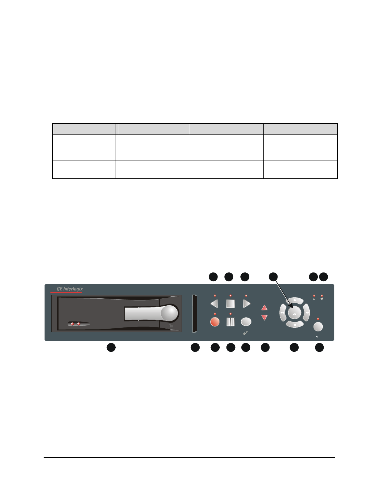
Figure 1-2 Front Panel
e
10 11 13 14
REVERSE PLAY STOP
PLAY
12
POWER ALARM
REC/PLAY
SPEED
ENTER
Kalatel VDR
RECORD PAUSE
SEARCH
1
1. Removable Hard Drive: Drives are removable for archival purposes.
2. CompactFlash Storage Card Slot: Used to capture, retain, and transport selected video files.
3. Record button: Press this button to begin recording.
4. Pause button: Press this button to pause playback.
5. Search button: Press this button to enter the Search Filters menu.
6. Increase and Decrease Record Speed buttons: Press these buttons to increase or decrease
the Record or Playback speed.
7. Arrow Buttons: Controls Playback speed and menu selections.
8. Enter Button: Confirms selection in menus.
Kalatel VDR 1-2 0150-0255C
Page 7
9. Reverse play button: Press this button to playback video in reverse at the normal record speed.
10. Stop button: Press this button to stop Recording or Playback.
11. Play Forward button: Press this button to playback video at the normal record speed.
12. Menu Button: Provides access to on-screen menus.
13. Power On Indicator: Indicates power is on when LED is lit.
14. Alarm Indicator: Indicates an alarm condition when the LED is lit.
1.7 Back Panel Connections
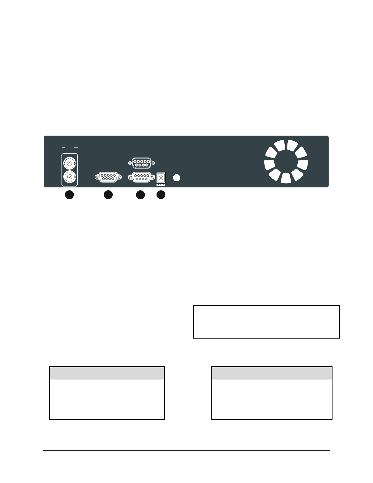
Figure 1-3 Back Panel
VIDEO
COMP
IN
RS-232 I/O
OUT
1 5
6
9
12V DC
1 2
3
4
1. Video In: Composite video input with BNC style connector.
Video Out: Composite video output with BNC style connector.
2. RS-232 Serial Port: Serial port for Flash Upgrading of software. Also for external control of
unit.
3. I/O Port: For connecting peripheral devices such as alarm devices, alarm relays, or the VEXT
connection.
4. Power Connector: Connect 12 Volt DC external power supply.
Video Input and Output
The unit is equipped with a Composite input and
output. The video input is auto terminating.
Composite Input: 75 Ohm BNC connector.
Composite Output: 75 Ohm BNC connector.
Composite Looping: Yes, while unit is On or Off.
Power Connector
Power Supply Input
Voltage: 120 to 240 Volt AC
Tolerance: ±10%
Frequency: 50 to 60 Hz
Voltage: 12 Volt DC
Power Supply Output
Power: 35 Watt
Connector: 2.1mm barrel, Center
Positive
0150-0255C 1-3 Kalatel VDR
Page 8
RS-232 Serial Port
1
5
6
9
1
5
6
9
Use a Null Modem cable when connecting to a
PC. When connecting to a multiplexer, it may
be necessary to construct a cable using the pinout documentation of the MUX as a guide. See
the pin-out configuration for the VDR below.
Connector Type: DB-9
Gender (on unit): Male
Cable Required (Connected to PC): Null Modem
Cable Required (Connected to Multiplexer):
Variable, depending on pin-out configuration of
MUX.
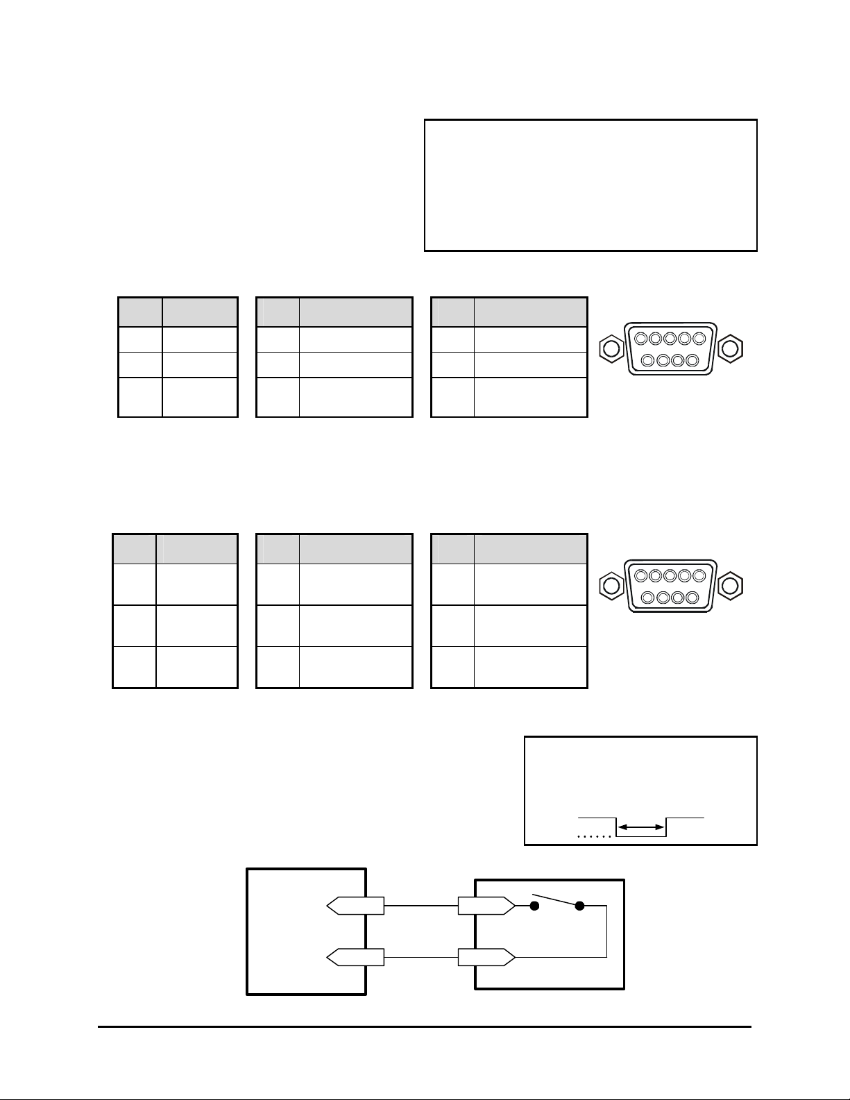
DB-9 Pin Configuration for Serial Port
Pin Use
Pin Use
1 DCD 4 Not Connected 7 RTS
2 RX 5 Ground 8 CTS
3 TX 6 Not Connected 9 Not Connected
Pin Use
DB-9 Connector on
1.8 Accessories I/O Port
The back panel of the unit is equipped with an Accessories Port (DB-9 style connector) for
connecting peripheral devices such as alarm devices, alarm relays, or the VEXT connection.
Do not attempt to wire accessories directly to the DB-9 connector.
Pin Use
Pin Use
Pin Use
RS-232
Back Panel
I/O
1 Alarm In 4
Alarm Record
7 Ground
Reset
2 Alarm Out 5
VEXT Pulse
8 Videoloss Out
Out
3
Record
6 Error Out 9 Disk End Out
Start In
Alarm In
An alarm condition can be activated by an Active Low TTL input
or by relay contact devices such as pressure pads, passive
infrareds, door switches, or other similar devices.
Figure 1-4 Normally Open Relay Alarm Connection
Alarm Input
Ground
Accessories PCB
Pin 1
Pin 7 or 10
Input: Active Low TTL w/ pull-ups
or Normally Open Relay.
High: 5V (12V tolerant)
Low: Ground
Normally Open
(Closes During Alarm)
Typical Alarm Device
Refer to each alarm devices's
manual for specific wiring details.
Minimum Duration: 0.5 Seconds
DB-9 Connector on
Back Panel
Kalatel VDR 1-4 0150-0255C
Page 9
Alarm Out
The Alarm output is activated while the Alarm Input is active.
The Alarm output is only active for the duration of the alarm
event.
Record Start In
Record Start In will place the unit in Record mode when
activated. Compatible with the Disk End Out signal from a
second unit.
Alarm Record Reset
This feature is for future development, and has not yet been implemented.
VEXT Pulse Out
The Video External Pulse connection (VEXT) simplifies
multiplexer operation by automatically synchronizing the
Multiplexer and the VDR.
The VDR sends a VEXT pulse to the Multiplexer indicating that it
is ready to record the next image. The Multiplexer responds by
sending the next image to the Video Input on the VDR.
The VEXT connection is especially beneficial for units
configured with dual record speeds (Normal and Alarm).
Output: Active Low
High: 12V
Low: Ground
Current Out: 50mA Max
Short Circuit Protected.
Input: Active Low TTL w/ pull-ups
or Normally Open Relay.
High: 5V (12V tolerant)
Low: Ground
Output: Active Low
High: 5V
Low: Ground (0.8V Max)
Current Out: 50mA Max
Short Circuit Protected.
Low for duration of alarm.
Minimum Duration: 0.5 Seconds
Use of the VEXT connection is Highly Recommended when
connecting the unit to a multiplexer.
Error Out
The Error Out signal is activated when the unit experiences any
operational or internal error.
Output: Open Collector
High: Transistor Off
Low: Transistor On
Active When On.
Current Out: 10mA Max
Minimum Duration: 0.5 Seconds
Videoloss Out
The Videoloss Out signal is activated when the unit experiences
videoloss on the video input (Composite).
In the event of videoloss, VIDEOLOSS will be indicated near the
upper left hand corner of the primary monitor.
0150-0255C 1-5 Kalatel VDR
Output: Open Collector
High: Transistor Off
Low: Transistor On
Active When On.
Current Out: 10mA Max
Minimum Duration: 0.5 Seconds
Page 10
Disk End Out
The Disk End Out is activated when there is 5 minutes of
recording space left on the hard disk. The VDR must be in
Record mode and set to Continuous Overwrite mode.
Output: Open Collector
High: Transistor Off
Low: Transistor On
Active When On.
Current Out: 10mA Max
Minimum Duration: 0.5 Seconds
1.9 Setting the Time and Date
It is recommended that, as a minimum, the following menu items be configured before using the unit.
For detailed information about using the menu system, see section 3.
o Main Menu → Time/Date → Set Time Format
To set the Time format, use the Arrow buttons to select the desired
Time format. Format the time as either:
• 12 HOUR
• 24 HOUR
Press the Enter button to confirm the selection and exit the menu.
--OR—
Press the Menu button to exit the menu without making changes.
Time Format Setup
Select Format
12 Hour
o Main Menu → Time/Date → Set Date Format
To set the Date format, use the Arrow buttons to select the desired Date
format. Format the Date as either:
• DD/MM/YY
• MM/DD/YY
• YY/MM/DD
Press the Enter button to confirm the selection and exit the menu.
--OR—
Press the Menu button to exit the menu without making changes.
Date Format Setup
Select Format
MM/DD/YY
Kalatel VDR 1-6 0150-0255C
Page 11
o Main Menu → Time/Date → Set Time
To set the Time:
1. With HH MM SS highlighted, press the Enter button. The highlighting
will move to the row of numbers.
2. Enter the time in Hours, Minutes, and Seconds. Use the to change
the values. Use the Arrow buttons to navigate among the three
fields.
3. Press the Enter button to confirm the selection.
4. To Save the changes and Exit the menu: Use the Arrow buttons
to select [OK], then press the Enter button.
--OR--
5. To Exit the menu without making changes: Use the Arrow
buttons to select [CANCEL], then press the Enter button.
o Main Menu → Time/Date → Set Date
To set the Date:
1. With MM DD YY DAY highlighted, press the Enter button. The
highlighting will move to the row of numbers.
2. Enter the date in Months, Days, and Years. Day of the Week
will update automatically. Use the Arrow buttons to change
the values. Use the Arrow buttons to navigate among the
three fields.
Time Setup
HH MM SS
03 05 53
[CANCEL] [OK]
Date Setup
MM DD YY DAY
12 17 00 SUN
[CANCEL] [OK]
3. Press the Enter button to confirm the selection.
4. To Save the changes and Exit the menu: Use the Arrow
buttons to select [OK], then press the Enter button.
--OR--
5. To Exit the menu without making changes: Use the Arrow
buttons to select [CANCEL], then press the Enter button.
1.10 Setting the Alarms
o Main Menu → Alarms
Use this menu to specify:
• Whether an alarm condition will be activated when the
unit detects a signal on the Alarm In connection.
• Whether the internal buzzer is activated during an
alarm condition.
Alarms Menu
Hardwire Alarm : Enable
Alarm Buzzer : Enable
[CANCEL] [OK]
0150-0255C 1-7 Kalatel VDR
Page 12
345
3
To configure the alarm settings:
1. Use the Arrow buttons to navigate among the fields.
2. Use the Arrow buttons to change the values of the
highlighted fields.
3. To Save the changes and Exit the menu: Use the
Arrow buttons to select [OK], then press the Enter
button.
--OR--
4. To Exit the menu without making changes: Use the
Arrow buttons to select [CANCEL], then press the
Enter button.
Hardwire Alarm : Enable
Alarm Buzzer : Enable
[CANCEL] [OK]
Alarms Menu
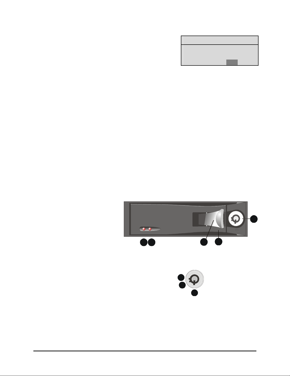
1.11 The Removable Hard Drive
The Kalatel VDR has a built-in removable hard drive that comes in 40, 80, and 160 GB models. The hard
drive is hot swappable; meaning the VDR need not be powered down before drive removal. However, it is
recommended that the drive not be removed during any drive activity (read/writes).
Whatever state (recording, playback) the drive is operating in, when it is removed, is the same state it will
start up in when reinstalled.
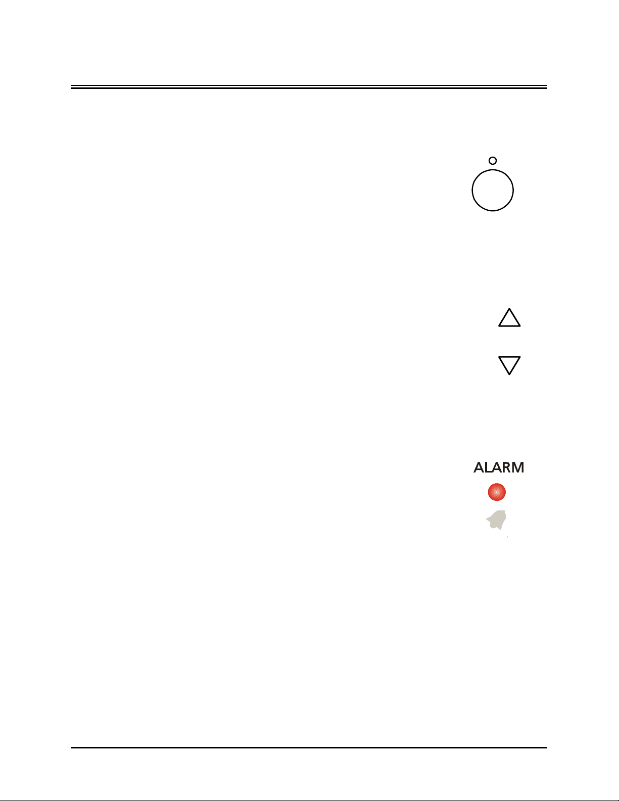
Hard Drive Front Panel
1. Hard Drive Activity LED, Amber.
2. Power Indicator, Green.
3. Active Handle (Shown Open).
4. Handle.
5. Key Lock.
Key Lock
1. Power On. Drive Locked
2. Power Off. Drive Locked.
3. Power Off. Drive Unlocked. (Shown)
1 2
1
2
Kalatel VDR 1-8 0150-0255C
Page 13
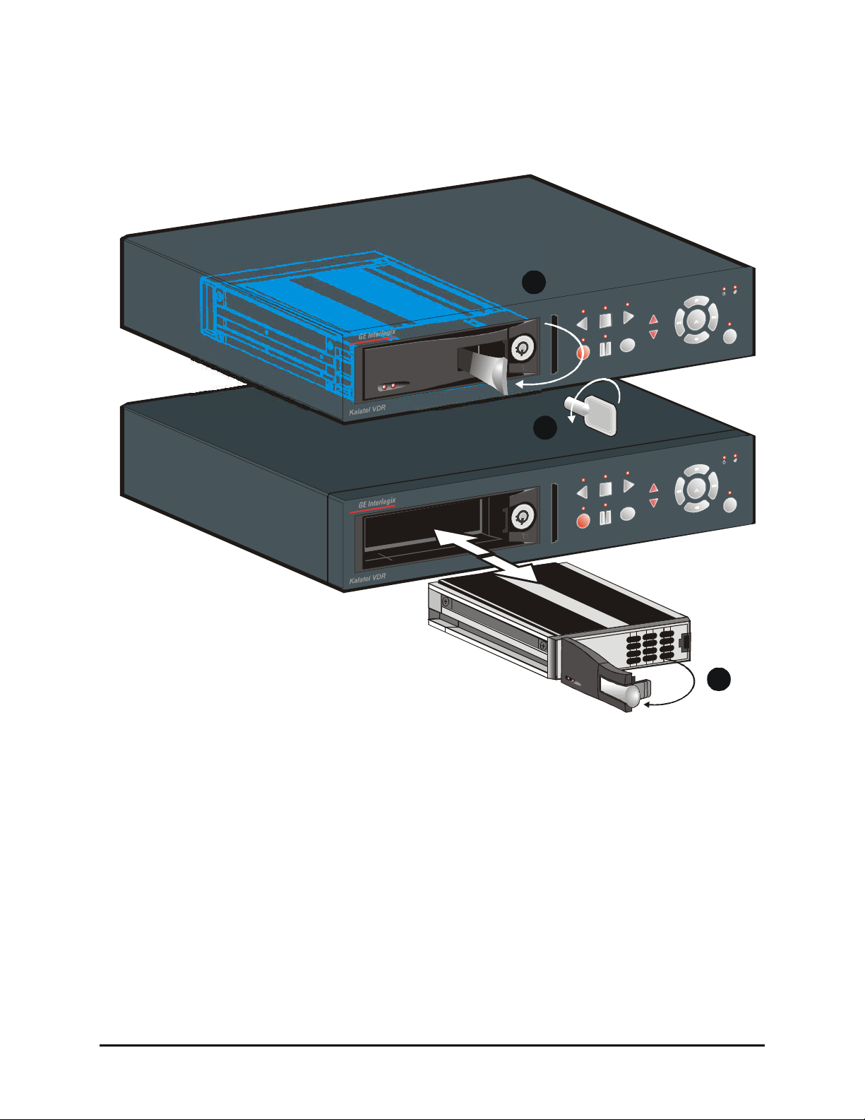
1.12 Removing the Hard Drive
213
1. Pull the active handle outward.
2. Use the key provided and place the key lock in position 3
shown above (rotate counter clockwise).
3. Pull the handle outward and slide the carrier body away from the cartridge frame.
To reinsert the drive perform the above steps in reverse. The Kalatel VDR will reset when the
drive is installed.
1.13 Using CompactFlash Storage Cards
The VDR uses industry standard Type I CompactFlash Storage Cards of varying capacities up to 512Mb
(See Section 8 for tested manufacturers). The CompactFlash cards can be used to store, retrieve, and
transport selected video files. The video files can be played back using GE Interlogix QuickWave software
that is automatically copied to the CF card. GE Interlogix recommends that upon initial use a minimum of
two CF cards be purchased. One CF card is used to create a Master CF card and the other(s) for the
copying and transfer of video files.
0150-0255C 1-9 Kalatel VDR
Page 14
Master CF card
The Master CF card is used to store and transfer the resident QuickWave application back onto Blank
HDD’s that can be inserted into the VDR. A blank HDD is defined as one not containing QuickWave
software.
Creating a Master CF card
Upon initial use of the VDR:
1. Insert the selected CF card to be used as a Master in the CF card slot with the label (top)
facing to the right. Slide in the card until it is firmly seated in the socket. The following message
will appear.
Compact Flash
Compact Flash detected. Initializing...
2. If the CF card is formatted QuickWave will be copied to it without any user intervention. A
“Writing QuickWave” status bar will display. To format an unformatted CF card please go the
Format command in the Main Menu under Compact Flash. The Format command places a
FAT16 file system on the CF card. Please note that formatting the CF card permanently erases
any data currently stored on that card. After formatting, QuickWave is automatically copied to
the CF card.
3. Remove the Master CF card and label it “Master CF card”. GE Interlogix recommends that this
Master CF card be stored in a safe place for use whenever a new and blank HDD is inserted
into the VDR.
NOTE
To Use a CF card:
1. Stop all recording or playback operations on the VDR.
2. Insert the CF card into the CF card slot with the label (top) facing to the right. Slide in the card
Note: When a new HDD is detected in the VDR, the VDR will request that the Master
CompactFlash be inserted in the CF card slot so that QuickWave may be copied to it.
Units equipped from the factory with HDDs have QuickWave preinstalled.
until it is firmly seated in the socket. The following message will appear.
Kalatel VDR 1-10 0150-0255C
Page 15

Compact Flash
Compact Flash detected. Initializing...
4. When this message disappears the CF card is ready for use. The first time a CF card is used
we recommend that the card be formatted using the Format command in the Main Menu under
Compact Flash. The Format command places a FAT16 file system on the CF card. Please note
that formatting the CF card permanently erases any data currently stored on that card.
5. Once Formatting is complete the CF card will be ready for use. For detailed information on the
Storage and Retrieval of data, please see Section 4.6 Main Menu → CompactFlash.
6. Once operations are complete remove the CF card by grasping it with your thumb and forefinger
and pulling it out of the CF card slot.
0150-0255C 1-11 Kalatel VDR
Page 16

Page 17
2 USER OPERATIONS
2.1 Recording
To begin recording, press the Record button. RECORD will be indicated for
three seconds, near the upper left hand corner of the primary monitor. The
unit always starts recording at the end of the previously recorded data.
Recording will continue until:
• Another mode is selected (Play mode, or Stop mode).
• The disk is full (In No Overwrite and Overwrite Once modes).
See section 5.1 Advanced Menu → Disk Overwrite Mode on
page 5-1, for details regarding Disk Overwrite modes.
Normal Recording
The unit records at the normal record speed until an alarm condition is detected.
The normal record speed is indicated on the LCD, and can be altered using the
Up/Down Record Speed buttons, or in the menu system.
For information about altering the normal record speed from the menu system, see
Main Menu → Record Settings → Normal Record Speed, on page 4-5 of the
Operator Programming section of this manual.
The normal record speed can be altered while the unit is recording. The unit will
continue recording while the menu system is active.
RECORD
Record button
REC/PLAY
SPEED
Record Speed
buttons
Alarm Recording
When an alarm condition is detected, the unit automatically switches to the
alarm record speed. The alarm condition is indicated in several ways:
• With the word ALARM, displayed on the primary monitor, near the
upper left hand corner of the screen.
• With the LED Alarm Indicator on the front panel of the unit.
• With the internal buzzer (if activated in the menu system). For
information about activating the internal buzzer during alarms, see
Main Menu → Alarms on page 4-3 of the Operator programming
section of this manual.
• By an external device, connected to the alarm output of the unit (if
the unit is installed that way).
The alarm record speed cannot be changed using the Up/Down Record Speed buttons on the front
panel. The alarm record speed must be changed in the menu system. For information about altering
the alarm record speed, see Main Menu → Record Settings → Alarm Record Speed, on page 4-5
of the Operator Programming section of this manual.
The unit returns to the normal record speed when the alarm condition ends.
Alarm Indicator
0150-0255C 2-1 Kalatel VDR
Page 18

Disk Nearly Full Notification
This message will appear on the primary monitor to
indicate that the unit has stopped recording, because
the disk is full.
In No Overwrite mode: The user must acknowledge
the on-screen message by pressing the Enter button.
Unit will not record over previously recorded data. To continue recording, the data must be erased (or
deleted) in the Advanced → Disk Maintenance menu.
In Overwrite Once mode: The user must acknowledge the on-screen message by pressing the Enter
button.
The unit will continue recording again when the user presses the Record button.
Disk Full. Recording Has Stopped.
Message
[OK]
2.2 Playback
Play Forward
To begin normal playback, press the Play Forward button. The unit will begin
playing back data from the beginning of the last recording session.
Playback is indicated:
• As PLAY near the upper left hand corner of the primary monitor, for
three seconds.
PLAY
Play Forward
button
Reverse Play
To begin reverse playback, press the Reverse play button. The unit will begin
playing back data from the beginning of the last recording session.
Reverse playback is indicated:
• As REVERSE PLAY near the upper left hand corner of the primary
monitor, for three seconds.
If there is only one recording session on the hard disk, the unit will indicate START
OF DATA on the primary monitor.
Playback Speed
The unit will playback the data at the rate it was recorded. The user can alter the
playback speed using the Up/Down Record Speed buttons.
Altering the playback speed overrides any change in playback speed that would
occur due to an alarm condition in the playback. To clear the override, press the
Stop button, then press the Play button to resume playback at the speed the data
was recorded.
REVERSE PLAY
Reverse play
button
REC/PLAY
SPEED
Record Speed
buttons
Kalatel VDR 2-2 0150-0255C
Page 19

Fast Forward
During playback, press the Fast Forward button. The unit will display images at
a higher than normal rate. There are 4 Fast Forward rates. Repeated pressing of
the Fast Forward button will increase the playback speed.
Fast Forward is indicated:
• As FAST FORWARD near the upper left hand corner of the primary
monitor, for three seconds.
Rewind
During playback, press the Rewind button. The unit will display images (in
reverse) at a higher than normal rate. There are 4 Rewind rates. Repeated
pressing of the Rewind button will increase the rewind speed.
Rewind is indicated:
• As REWIND near the upper left hand corner of the primary monitor, for
three seconds.
Pause
During playback, press the Pause button to pause playback, and display a single
frame on-screen.
Pause is indicated:
• As PAUSE near the upper left hand corner of the primary monitor, for
three seconds.
Single Frame Advance
Fast Forward
Button
Rewind Button
PAUSE
Pause button
While in Pause mode, press the Single Frame Advance button. The unit will
advance a single frame, then return to Pause mode.
Single Frame
Advance Button
Single Frame Rewind
While in Pause mode, press the Single Frame Rewind button. The unit will
rewind a single frame, then return to Pause mode.
Single Frame
Rewind Button
Start of Data & End of Data
If the start or end of data is reached during playback, START OF DATA or END OF DATA is indicated
near the upper left hand corner of the primary monitor.
2.3 The Search Interface
The Search Interface feature allows the user to search the hard disk for recorded
events, such as an alarm condition, or a previous recording session. For example,
each time Record mode is activated, it is considered a separate recording
session.
To enter the Search Filters menu, press the Search button. The Search Filters
menu is displayed on the primary monitor.
Search button
0150-0255C 2-3 Kalatel VDR
Page 20

Use this to specify:
Search Filters
• The Start and Stop date of
the search.
• The Start and Stop time of
the search.
• To search for recorded
alarms.
Start
DATE: 12/25/00 [ ]
(MM/DD/YY)
Start
TIME: 11:11:21 [ ]
ALARM: [ ]
[CANCEL] [START SEARCH]
Stop
01/01/01 [ ]
(MM/DD/YY)
Stop
12:34:34 [ ]
Searching for All Recorded Events
Using the Arrow buttons to navigate, highlight [START SEARCH], then press the Enter button. The
Search Results window will appear. For information about selecting a recorded event, see Selecting
from the Search Results, in this section.
2.4 Specifying Search Parameters
Selecting a Start and Stop Date
1. Using the Arrow buttons to navigate, highlight the DATE parameter, then press the Enter button.
The unit will enter Edit mode.
2. Use the Arrow buttons to change the start and stop date values. Use the Arrow buttons to
navigate among the different parameters.
3. To activate the start or stop date parameter, use the Arrow buttons to place an [X] in the check
box.
4. Press the Enter button at any time to exit Edit mode.
Selecting a Start and Stop Time
1. Using the Arrow buttons to navigate, highlight the TIME parameter, then press the Enter button.
The unit will enter Edit mode.
2. Use the Arrow buttons to change the start and stop time values. Use the Arrow buttons to
navigate among the different parameters.
3. To activate the start or stop time parameter, use the Arrow buttons to place an [X] in the check
box.
4. Press the Enter button at any time to exit Edit mode.
Searching for Recorded Alarms
1. Using the Arrow buttons to navigate, highlight the ALARM parameter, then press the Enter button.
The unit will enter Edit mode.
2. Use the Arrow buttons to activate the alarms search, by placing an [X] in the check box.
3. Press the Enter button at any time to exit Edit mode.
Kalatel VDR 2-4 0150-0255C
Page 21

Starting the Search
Using the Arrow buttons to navigate, highlight the [START SEARCH] parameter, then press the Enter
button. The Search Results menu will appear.
Search Results
4 matches found.
“ENTER” to play
000
001
002
003
Start Date
01/01/00
01/01/00
02/12/00
02/12/00
Start Time
00:07:14
23:35:20
23:43:30
00:17:23
Days HH MM SS
0 00:00:36
0 00:08:11
0 00:33:49
0 01:38:18
Selecting from the Search Results
Use the Arrow buttons to select a recorded event.
Press the Enter button to select the event, or press the Menu button to exit the Search Results menu.
0150-0255C 2-5 Kalatel VDR
Page 22

Kalatel VDR 2-6 0150-0255C
Page 23

3 T HE MENU SYSTEM
MENU
MENU
This section provides a brief overview of the menu system, for complete information about Operator
and Installer programming, see section 4: Operator Programming, or section 5: Installer
Programming.
How to use this Manual
Throughout this manual, there are headings like these.
o Main Menu → Timer Settings
Meaning: From the Main menu, select TIMER SETTINGS, then press the Enter button. A Pop-up or
Pull down menu will appear.
o Main Menu → Record Settings → Normal Record Speed
Meaning: From the Main menu, select RECORD SETTINGS, then press the Enter button. This opens
another menu. In this menu, select NORMAL RECORD SPEED, then press the Enter button.
A Pop-up or Pull down menu will appear.
Pull-down Menus
Pull-down menus are the top-level menus. Make a selection in a Pull-down menu to enter the
appropriate sub-menu (typically a Pop-up menu). Changes to the unit's parameters are usually made
in Pop-up menus.
To exit a Pull-down menu, press the Menu button.
Pop-up Menus
Pop-up menus usually have a parameter (or several parameters), from which the user can make a
selection or change the value.
Use the Arrow buttons to select a new parameter and to change the value of that parameter.
To Save changes and Exit the menu: Select [OK], the press the Enter
button.
To Exit the menu without making changes: Press the Menu button or
select [CANCEL], then press the Enter button.
In some boxes, items are highlighted on the screen. They are represented in this manual as follows:
Not highlighted: Highlighted:
TIME/DATE ALARMS
Menu button
Entering the Main menu
Enter the Main menu by pressing the Menu button. The Main menu will
appear on the primary monitor.
0150-0255C 3-1 Kalatel VDR
Menu button
Page 24

The Arrow Buttons
Up Arrow Button
Right Arrow
Down Arrow Button
When in the Main Menu the Arrow buttons are used to navigate and modify field values.
Left Arrow
Button
MENU
Button
The Main Menu
The Main menu provides access to all of the operator programmable
options. Each sub-section of the Main menu is described briefly in this
section.
For complete information about operator programming in the Main menu,
see section 4.
o Main Menu → Advanced Menu
To access the Advanced menu:
1. Select ADVANCED MENU from the Main menu, then
press the Enter button. The Password Box will
appear.
2. Enter the Advanced menu password. Use the Arrow
buttons to select a character, then use the Enter
button to complete the selection, and move to the next
character.
Time/Date
Alarms
Timer Settings
Record Settings
Display Settings
CompactFlash
Advanced Menu
About
Password Box
Please Enter The Password!
0---
The Advanced Menu
For security reasons, a password is provided to limit access to the
Advanced menu. For instructions about entering the Advanced menu,
see Main Menu → Advanced Menu, on the previous page.
The Advanced menu provides access to all of the installer
programmable options. Each sub-section of the Advanced menu is
described briefly in this section.
For complete information about installer programming in the Advanced
menu, see section 5.
Kalatel VDR 3-2 0150-0255C
3. Pressing the Enter button on the last character will
complete the password selection and the unit will
display the Advanced menu.
Disk Overwrite Mode
Disk Maintenance
Auto Delete Mode
Adjust Picture
Front Panel Lock
Factory Settings
Change Password
Firmware Upgrade
Page 25

4 OPERATOR PROGRAMMING
4.1 Main Menu → Time/Date
Use this menu to specify:
• The time format: 12 or 24 hours.
• The date format: MM/DD/YY, DD/MM/YY, or YY/MM/DD.
• The time.
• The date.
• Set the Region for the Auto Daylight Savings Time feature.
o Main Menu → Time/Date → Set Time Format
To set the Time format, use the Arrow buttons to select the desired
Time format. Format the time as either:
• 12 HOUR
• 24 HOUR
Press the Enter button to confirm the selection and exit the menu.
--OR—
Press the Menu button to exit the menu without making changes.
Set Time Format
Set Date Format
Set Time
Set Date
Set Region
Time Format Setup
Select Format
12 HOUR
o Main Menu → Time/Date → Set Date Format
To set the Date format, use the Arrow buttons to select the desired Date
format. Format the Date as either:
• DD/MM/YY
• MM/DD/YY
• YY/MM/DD
Press the Enter button to confirm the selection and exit the menu.
--OR—
Press the Menu button to exit the menu without making changes.
Date Format Setup
Select Format
MM/DD/YY
0150-0255C 4-1 Kalatel VDR
Page 26

o Main Menu → Time/Date → Set Time
To set the Time:
1. With HH MM SS highlighted, press the Enter button. The
highlighting will move to the row of numbers.
2. Enter the time in Hours, Minutes, and Seconds. Use the Arrow
buttons to change the values. Use the Arrow buttons to
navigate among the three fields.
3. Press the Enter button to confirm the selection.
4. To Save the changes and Exit the menu: Use the Arrow
buttons to select [OK], then press the Enter button.
--OR--
5. To Exit the menu without making changes: Use the Arrow
buttons to select [CANCEL], then press the Enter button.
o Main Menu → Time/Date → Set Date
To set the Date:
1. Press the Enter button. The highlighting will move to the row of
numbers.
2. Enter the date in Months, Days, and the Year. Day of the Week
will update automatically. Use the Arrow buttons to change
the values. Use the Arrow buttons to navigate among the
three fields.
Time Setup
HH MM SS
03 05 53
[CANCEL] [OK]
Date Setup
MM DD YY DAY
12 17 00 SUN
[CANCEL] [OK]
3. Press the Enter button to confirm the selection.
4. To Save the changes and Exit the menu: Use the Arrow
buttons to select [OK], then press the Enter button.
--OR--
5. To Exit the menu without making changes: Use the Arrow
buttons to select [CANCEL], then press the Enter button.
Kalatel VDR 4-2 0150-0255C
Page 27

o Main Menu → Time/Date → Set Region
Use this menu option to set the region for the Auto
Daylight Savings Time feature. Choices are:
Regional Settings
• OFF: Clock will not be changed automatically.
• USA: DST starts at 02:00 on the first Sunday in
April. DST ends at 02:00 on the last Sunday in
October. Includes: United States (except Hawaii,
American Samoa, Guam, Puerto Rico, Virgin
Islands, parts of Indiana and Arizona) and
Canada (except Saskatchewan).
• EUR: DST starts at 01:00 GMT on the last
Sunday in March. DST ends at 01:00 GMT on
the last Sunday in October. Includes: European
Union Countries.
• AUS: DST starts at 02:00 on the last Sunday in
October. DST ends at 03:00 on the last Sunday
in March. Includes: South Australia, Victoria,
ACT, NSW. Excludes: Tasmania.
The clock will only be automatically adjusted once on a given time and date. If you manually set the
clock back before the last DST change, the time will not get automatically adjusted again for that same
time change.
Daylight Saving :
Time Zone :
SUN, 6 APR 2003 02:00 (+1)
SUN, 26 OCT 2003 02:00 (-1)
[CANCEL] [OK]
USA
GMT+07:00
4.2 Main Menu → Alarms
Use this menu to specify:
• Whether an alarm condition will be activated when the
unit detects a signal on the Alarm In connection.
• Whether the internal buzzer is activated during an
alarm condition.
Hardwire Alarm : Enable
Alarm Buzzer : Enable
[CANCEL] [OK]
Alarms Menu
4.3 Main Menu → Timer Settings
This menu allows the user to
program a timed-recorded
event. Use this menu to
specify:
• The date, or days on
which the recording
will occur.
• The start and stop
time.
• The record speed.
• The record quality.
• Whether the event is
enabled.
0150-0255C 4-3 Kalatel VDR
DATE START STOP SPD(pps) QUALITY ON/OFF
31
Sat
Mon-Fri
Sat-Sun
Mon-Sun
--
EDIT Mode Hit "ENTER" To Toggle EDIT Mode
16:45
07:55
09:56
14:23
02:23
--:--
17:05
08:10
11:05
14:50
03:34
--:--
20
10
60
60
20
--
[OK]
High
Med
Low
High
Med
--
On
Off
On
On
Off
--
Page 28

Creating a Timed Recording:
1. Using the Arrow buttons to navigate, highlight the DATE parameter of the last line item (indicated
with double dash marks).
2. Press the Enter button to enter the Edit mode. EDIT MODE will appear on-screen, in the lower
left-hand corner of the Timer Settings menu. The user may press the Enter button to exit Edit
mode at any time.
3. Use the Arrow buttons to change the values of the DATE setting.
Date (Day of the Month)
Day of the Week
Range of Days
4. When finished entering the Date, use the Arrow buttons to navigate the START setting.
5. Use the Arrow buttons to enter the time the recording will begin. The Hours and Minutes are
edited separately. The start and stop times are always configured in a 24-hour clock. When
finished entering the start time, use the Arrow buttons to navigate to the STOP setting.
6. Use the Arrow buttons to enter the time the recording will end. Entering a time "before" the start
time will cause the unit to record until the indicated stop time on the next day. When finished
entering the stop time, use the Arrow buttons to navigate to the SPD setting.
7. Use the Arrow buttons to enter the record speed in pictures per second.
NTSC Record Speeds
PAL Record Speeds
8. When finished entering the Record Speed, use the Arrow buttons to navigate to the QUALITY
setting.
1 through 31
Monday through Sunday
All Weekdays (Monday-Friday), All Weekend Days (Saturday-Sunday),
Monday-Sunday (Everyday)
60, 30, 20, 10, 5, 3, 2, 1, 0.5, 0.2, 0.1, 0.0
50, 25, 17, 10, 5, 3, 2, 1, 0.5, 0.2, 0.1, 0.0
9. Use the Arrow buttons to enter the record quality (Low, Medium, or High). Higher record quality
settings use more disk space.
10. When finished entering the Record Quality, use the Arrow buttons to navigate to the ON/OFF
setting.
11. Use the Arrow buttons to Activate, Deactivate, or Delete the recording.
12. When finished, press the Enter button to exit the Edit mode. Use the Arrow buttons / Arrow
buttons to navigate to [OK], then press the Enter button to complete the selection.
Editing a Timed Recording:
1. Using the Arrow buttons to navigate, highlight the event parameter you wish to edit.
2. Press the Enter button to enter the Edit mode. EDIT MODE will appear on-screen, in the lower
left-hand corner of the pop-up menu.
3. Use the Arrow buttons to change the values. Use the Arrow buttons to navigate among
parameters in the same row.
4. When finished, press the Enter button to exit the Edit mode. Use the Arrow buttons to navigate
to [OK], then press the Enter button to complete the selection.
Kalatel VDR 4-4 0150-0255C
Page 29

Deleting a Timed Recording:
1. Using the Arrow buttons to navigate, highlight the ON/OFF parameter of the event you wish to
delete.
2. Press the Enter button to enter the Edit mode.
3. Use the Arrow buttons to select DEL from the menu.
4. Press the Enter button to confirm the selection and exit the Edit mode.
5. Use the Arrow buttons to navigate to [OK], then press the Enter button to remove the selection
and exit the menu.
4.4 Main Menu → Record Settings
Use this menu to specify:
• Color or Monochrome recording.
• The record speed during Normal recording.
• The record speed when the unit detects an alarm condition.
• The recorded picture quality.
Color/Mono
Normal Record Speed
Alarm Record Speed
Video Quality
o Main Menu → Record Settings → Color/Mono
This menu sets the recorded video to be in Color or Mono. If you select auto, (default), the
unit will auto detect color as before. If you select mono, it will force the recording into
monochrome. All recorded and looped video will be monochrome. Use the Arrow buttons
to select Auto or Mono.
Press the Enter button to conf irm the selection and exit the menu.
--OR—
Press the Menu button to exit the menu without making changes.
o Main Menu → Record Settings → Normal Record Speed
Use the Arrow buttons to select the desired Normal Record Speed.
Normal Record Speeds:
NTSC: 60, 30, 20, 10, 5, 3, 2, 1, 0.5, 0.2, 0.1, 0.0.
PAL: 50, 25, 17, 10, 5, 3, 2, 1, 0.5, 0.2, 0.1, 0.0.
When the Normal Record Speed is set to 0.0, the unit will only record
while an alarm is active.
Press the Enter button to confirm the selection and exit the menu.
--OR—
Normal Record Speed
Pictures Per Second
Auto
Mono
5p
Press the Menu button to exit the menu without making changes.
0150-0255C 4-5 Kalatel VDR
Page 30

o Main Menu → Record Settings → Alarm Record Speed
Use the Arrow buttons to select the desired Alarm Record Speed.
Alarm Record Speeds:
NTSC: 60, 30, 20, 10, 5, 3, 2, 1, 0.5, 0.2, 0.1.
PAL: 50, 25, 17, 10, 5, 3, 2, 1, 0.5, 0.2, 0.1.
Alarm Record Speed
Pictures Per Second
60p
Press the Enter button to confirm the selection and exit the menu.
--OR—
Press the Menu button to exit the menu without making changes.
o Main Menu → Record Settings → Video Quality
Use the Arrow buttons to select the desired Record Quality. Select High,
Med or Standard.
Higher record qualities use lower compression, requiring more disk space.
Press the Enter button to confirm the selection and exit the menu.
--OR—
Press the Menu button to exit the menu without making changes.
4.5 Main Menu → Display Settings
Use this menu to specify what status information will be displayed on
the primary monitor. Select On or Off, for the following items.
• The current time and date.
• The remaining amount of time before the hard disk runs
out of record space.
Record Quality
Select Quality
High
Current Time / Date
Record Capacity
Last Alarm
Record Playback Speed
Playback Time / Date
• The time and date of the last alarm.
• The Record or Playback Speed.
• During Playback, the time and date the recording was
made.
o Main Menu → Display Settings → Current Time / Date
To display the current Time and Date near the upper right hand corner of the primary monitor,
select ON. Use the Arrow buttons to select On or Off.
Press the Enter button to confirm the selection and exit the menu.
--OR—
Press the Menu button to exit the menu without making changes.
Kalatel VDR 4-6 0150-0255C
OFF
ON
Page 31

o Main Menu → Display Settings → Record Capacity
Select ON, to display the amount of time remaining before the hard disk runs out of record
space. The data is displayed near the upper left hand corner of the primary monitor. The unit
displays the Record Capacity with two measures of time, and switches automatically
depending on the amount of time remaining:
• Days and Hours
• Hours and Minutes
• Minutes and Seconds
Use the Arrow buttons to select ON or OFF.
Press the Enter button to confirm the selection and exit the menu.
--OR—
Press the Menu button to exit the menu without making changes.
o Main Menu → Display Settings → Last Alarm
To display the time and date of the last alarm, near the upper right hand corner of the primary
monitor, select On. The unit will display NONE if there is no previous record of an alarm.
Use the Arrow buttons to select On or Off.
Press the Enter button to confirm the selection and exit the menu.
--OR—
OFF
ON
OFF
ON
Press the Menu button to exit the menu without making changes.
o Main Menu → Display Settings → Record Playback Speed
To display the Record or Playback Speed, near the lower right hand corner of the primary
monitor, select On. The unit will display NONE if there is no previous record of an alarm.
Use the Arrow buttons to select On or Off.
Press the Enter button to confirm the selection and exit the menu.
--OR—
Press the Menu button to exit the menu without making changes.
o Main Menu → Display Settings → Playback Time / Date
To display the time and date the recording was made (during playback) select On. The data is
displayed near the upper right hand corner of the screen.
Use the Arrow buttons to select On or Off.
Press the Enter button to confirm the selection and exit the menu.
--OR—
OFF
ON
OFF
ON
Press the Menu button to exit the menu without making changes.
0150-0255C 4-7 Kalatel VDR
Page 32

4.6 Main Menu → CompactFlash
Use this menu to search for, retrieve, and store video files. Select Main Menu
→ CompactFlash to display the CompactFlash commands. Select from the
following items.
• Store: Search by Time, Date, or Alarm and Store selected files to
CF card.
• Retrieve: Search by Time, Date, or Alarm and Retrieve selected
files from CF card to the VDR.
• Format: Prepare the CF card for use or erase files previously
stored.
o Main Menu → CompactFlash → Store
Once this command is selected the CompactFlash Store Search Filters Menu will appear.
Use this to specify:
• The Start and Stop date of
the search.
• The Start and Stop time of
the search.
• Whether to search for an
alarm.
Compact Flash Store Search Filters
Start Stop
DATE: 10/21/03 [ ] 10/21/03 [ ]
(MM/DD/YY) (MM/DD/YY)
Store
Retrieve
Format
Start Stop
TIME: 15:09:47 [ ] 15:09:47 [ ]
ALARM: [ ]
Searching for All Recorded Events
Using the Arrow buttons to navigate, highlight [START SEARCH], then press the Enter button. The
Search Results window will appear. For information about selecting a recorded event, see Selecting
from the Search Results, in this section
Selecting a Start and Stop Date
1. Using the Right or Left Arrow buttons to navigate, highlight the DATE parameter, then press the
Enter button. The unit will enter Edit mode.
Kalatel VDR 4-8 0150-0255C
Page 33

2. Use the Up or Down Arrow buttons to change the start and stop date values. Use the Right or
Preview Mode
‘MENU’ to Return
Left Arrow buttons to navigate among the different parameters.
3. To activate the start or stop date parameter, use the Up or Down Arrow buttons to place an
[X] in the check box.
4. Press the Enter button at any time to exit Edit mode.
Selecting a Start and Stop Time
1. Using the Right or Left Arrow buttons to navigate, highlight the TIME parameter, then press the
Enter button. The unit will enter Edit mode.
2. Use the Up or Down Arrow buttons to change the start and stop time values. Use the Right or
Left Arrow buttons to navigate among the different parameters.
3. To activate the start or stop time parameter, use the Up or Down Arrow buttons to place an
[X] in the check box.
4. Press the Enter button at any time to exit Edit mode.
Searching for Recorded Alarms
1. Using the Right or Left Arrow buttons to navigate, highlight the ALARM parameter, then press
the Enter button. The unit will enter Edit mode.
2. Use the Up or Down Arrow buttons to activate the alarms search, by placing an [X] in the check
box.
3. Press the Enter button at any time to exit Edit mode.
Starting the Search
Using the Right or Left Arrow buttons to navigate, highlight the [START SEARCH] parameter, then
press the Enter button. The Search Results menu will appear.
Preview the Selected Files
Once the selected files are displayed you have the option of previewing the files before copying them to
the selected device by hitting the Enter button. Use the Up or Down Arrow buttons to highlight a
recorded event and hit the Enter button. The highlighted file will begin playing. When that file is finished
the next file on the list will play. The following display will also appear to indicate the system is in Preview
Mode.
Hit the Menu button to return to the Search Screen,
0150-0255C 4-9 Kalatel VDR
Page 34

Compact Flash Store Search Results
[CANCEL]
Start Date Start Time Size (MB)
000 10/16/03 09:27:18 28 [ ]
001 10/16/03 09:28:04 2 [x]
002 10/16/03 09:28:06 2 [x]
003 10/16/03 14:04:54 18 [ ]
004 10/16/03 18:10:19 18208 [ ]
005 10/22/03 07:56:40 2 [x]
006 10/22/03 07:57:08 2 [ ]
007 10/22/03 07:57:09 4 [ ]
008 10/22/03 08:01:40 2 [ ]
009 10/22/03 08:01:42 2 [ ]
29 Matches Found
Selected [ 8](MB)
Available on Target Medium [ 10](MB)
‘LEFT’/’RIGHT’ to select or deselect
‘ENTER’ to Preview ‘SEARCH’ to Store
Selecting from the Search Results
1. Use the Up or Down Arrow buttons to highlight a recorded event.
2. Use the Right or Left Arrow buttons to select a recorded event by placing an [X] in the check box.
Please note the size of the file or files selected cannot exceed the capacity of the targeted device.
Storing the Search Results
Hit the Search button to begin the file copying process. A progress
bar will display until the operation is complete.
When finished the system will display a Storing Complete Message Box. At this point it will be safe to
remove the CF card from the VDR. The video files can be played back using GE Interlogix QuickWave
software that is automatically copied to the CF card. The files may also be copied and viewed on any PC
equipped with a CF card reader.
Message
Storing Complete.
[OK]
Storing
Kalatel VDR 4-10 0150-0255C
Page 35

o Main Menu → CompactFlash → Retrieve
Compact Flash Retrieve Search Filters
DATE: 10/21/03 [ ] 10/21/03 [ ]
TIME: 15:09:47 [ ] 15:09:47 [ ]
Once this command is selected the CompactFlash Retrieve Search Filters Menu will appear.
Use this to specify:
• The Start and Stop date of
the search.
• The Start and Stop time of
Start Stop
the search.
(MM/DD/YY) (MM/DD/YY)
• Whether to search for an
alarm.
Start Stop
ALARM: [ ]
Searching for All Recorded Events
Using the Arrow buttons to navigate, highlight [START SEARCH], then press the Enter button. The
Search Results window will appear. For information about selecting a recorded event, see Selecting
from the Search Results, in this section
Selecting a Start and Stop Date
1. Using the Right or Left Arrow buttons to navigate, highlight the DATE parameter, then press the
Enter button. The unit will enter Edit mode.
2. Use the Up or Down Arrow buttons to change the start and stop date values. Use the Right or
Left Arrow buttons to navigate among the different parameters.
3. To activate the start or stop date parameter, use the Up or Down Arrow buttons to place an
[X] in the check box.
4. Press the Enter button at any time to exit Edit mode.
Selecting a Start and Stop Time
1. Using the Right or Left Arrow buttons to navigate, highlight the TIME parameter, then press the
Enter button. The unit will enter Edit mode.
2. Use the Up or Down Arrow buttons to change the start and stop time values. Use the Right or
Left Arrow buttons to navigate among the different parameters.
0150-0255C 4-11 Kalatel VDR
Page 36

3. To activate the start or stop time parameter, use the Up or Down Arrow buttons to place an
Retrieving
[CANCEL]
[X] in the check box.
4. Press the Enter button at any time to exit Edit mode.
Searching for Recorded Alarms
1. Using the Right or Left Arrow buttons to navigate, highlight the ALARM parameter, then press
the Enter button. The unit will enter Edit mode.
2. Use the Up or Down Arrow buttons to activate the alarms search, by placing an [X] in the check
box.
3. Press the Enter button at any time to exit Edit mode.
Starting the Search
Using the Right or Left Arrow buttons to navigate, highlight the [START SEARCH] parameter, then
press the Enter button. The Search Results menu will appear.
Compact Flash Retrieve Search Results
Start Date Start Time Size (MB)
000 10/16/03 09:27:18 28 [ ]
001 10/16/03 09:28:04 2 [ ]
002 10/16/03 09:28:06 2 [ ]
003 10/16/03 14:04:54 18 [ ]
004 10/22/03 07:56:40 2 [ ]
005 10/22/03 07:57:08 2 [ ]
006 10/22/03 08:01:40 2 [ ]
007 10/22/03 08:01:42 2 [ ]
8 Matches Found
Available on Target Medium [ 39104](MB)
‘LEFT’/’RIGHT’ to select or deselect
Selected [ 0](MB)
‘SEARCH’ to Store
Selecting from the Search Results
1. Use the Up or Down Arrow buttons to highlight a recorded event.
2. Use the Right or Left Arrow buttons to select a recorded event by placing an [X] in the check
box. Please note the size of the file or files selected cannot exceed the capacity of the targeted
device.
Retrieving the Search Results
Hit the Search button to begin the file copying process. A progress bar
will display until the operation is complete.
Kalatel VDR 4-12 0150-0255C
Page 37

When finished the system will display a Retrieving Complete Message Box. At this point it will be safe
to remove the CF card from the VDR. The files are now stored on the VDR’s Hard Drive.
Message
Retrieving Complete.
[OK]
o Main Menu → CompactFlash → Format
Use this command to prepare a new CF card for use in the VDR or erase files that are already stored
on the card. The Format command places a FAT16 file system on the CF card. Please note that
formatting the CF card permanently erases any data currently stored on that card. Selecting Format
will display the following warning.
Format
All data will be permanently erased!
Do you want to continue?
[CANCEL] [OK]
Selecting OK will begin the format process. The system will display a Format Complete message
when finished.
4.7 Main Menu → Advanced Menu
To access the Advanced menu:
1. Select ADVANCED MENU from the Main menu, then
press the Enter button. The Password Box will
appear.
2. Enter the Advanced menu password. Use the Arrow
buttons to select a character, then use the Enter
button to complete the selection, and move to the next
character.
Please Enter The Password!
Password Box
0---
3. Pressing the Enter button on the last character will
complete the password selection and the unit will
display the Advanced menu.
0150-0255C 4-13 Kalatel VDR
Page 38

4.8 Main Menu → About
[OK]
o Main Menu → About
Use this menu to display information about the VDR. Select Main Menu → About to display the About
screen.
Serial Number:
Software Version:
Software Date:
Software Checksum:
Boot Code Ver.:
Disk Size:
V301-9-3300005
1.05
Oct 15 2003 15:06:18
59767E0E
1.00
41.11 GB
Kalatel VDR 4-14 0150-0255C
Page 39

5 INSTALLER PROGRAMMING
For security reasons, a password is provided to limit access to the Advanced menu. For instructions
about entering the Advanced menu, see section 4.6 Main Menu → Advanced Menu, on page 4-8.
5.1 Advanced Menu → Disk Overwrite Mode
Use this menu to specify how the unit will handle disk overwrite
Disk Overwrite Mode
issues once the hard disk becomes full.
The unit handles disk overwrite issues in three ways:
• No Overwrite.
Continuous Overwrite
• Overwrite Once.
• Continuous Overwrite.
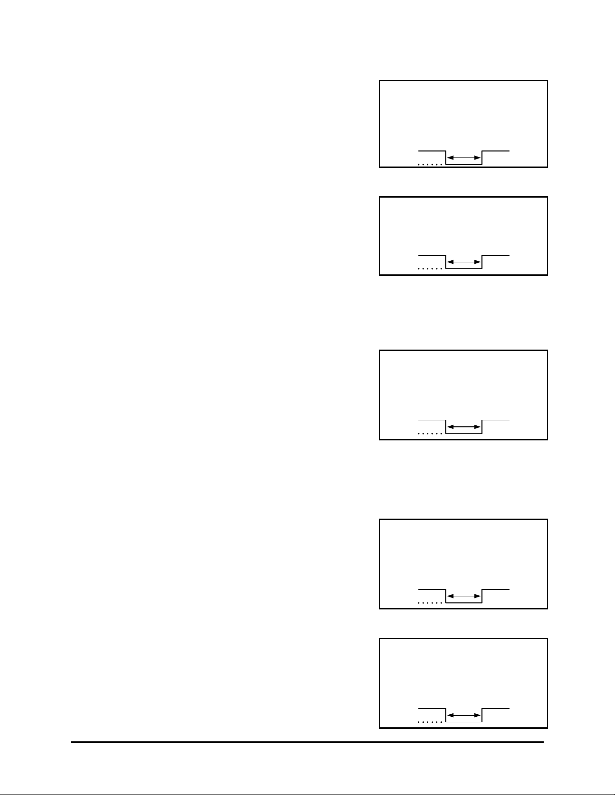
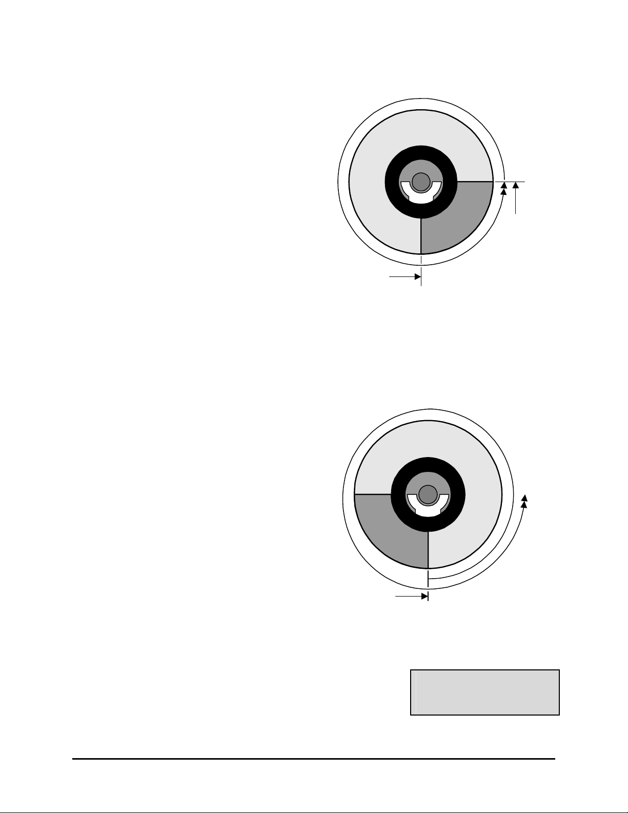
o Advanced Menu → Disk Overwrite Mode → No Overwrite
Functions of No Overwrite mode:
• Recording always starts at end of
last recording.
• Recording stops when end of disk is
reached (when disk is full).
• When the end of the disk is reached,
data
New recorded
the unit displays an on-screen
message indicating that the disk is
full, and the unit has stopped
recording. User must acknowledge
the on-screen message by pressing
the Enter button.
Select Mode
Previously
recorded data
Previously
recorded data
• Unit will not record over previously
recorded data. To continue
recording, the data must be erased
(or deleted) in the Advanced →
Disk Maintenance menu.
Unit Stops
Recording when this
point is reached
No Overwrite Mode
Physical Start
and End of Disk
0150-0255C 5-1 Kalatel VDR
Page 40
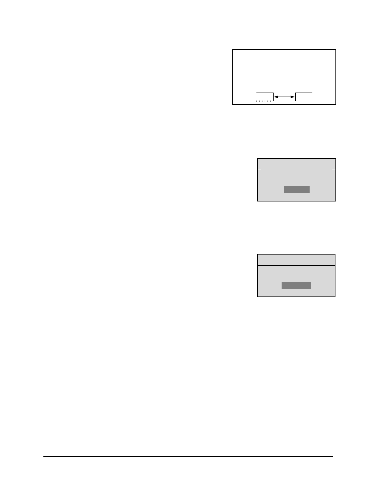
o Advanced Menu → Disk Overwrite Mode → Overwrite Once
Functions of Overwrite Once mode:
• Recording always starts at end of
last recording.
• The unit overwrites all previously
New recorded
data
recorded data.
• Recording stops before the unit
overwrites any of the newly recorded
data (data from the current record
session).
• When the end of the disk is reached,
the unit displays an on-screen
Previously
recorded data
message indicating that the disk is
full, and the unit has stopped
recording. User must acknowledge
Physical
Start of Disk
the on-screen message by pressing
the Enter button.
Overwrite Once Mode
• The unit will continue recording
again when the user presses the
Record button.
overwriten
Unit Stops
Recording
when this point
is reached
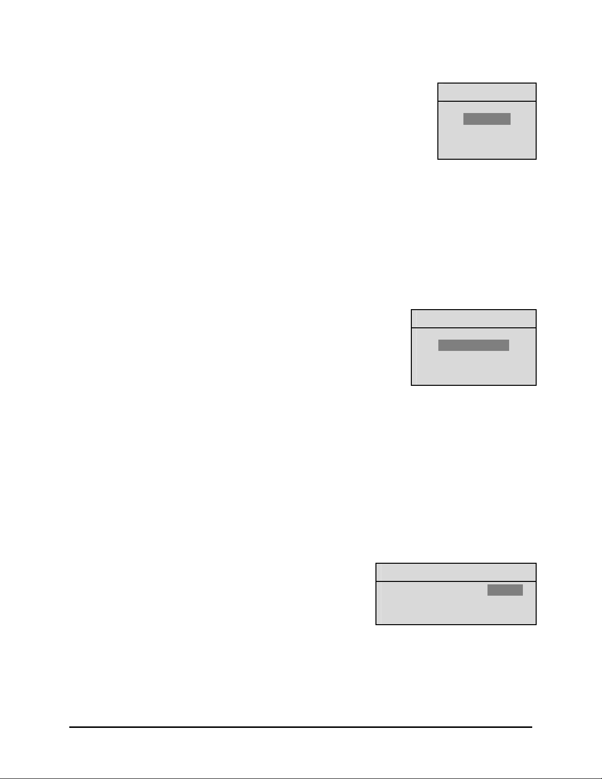
o Advanced Menu → Disk Overwrite Mode → Continuous Overwrite
Functions of Continuous Overwrite mode:
• Recording always starts at end of
last recording.
• The unit overwrites all previously
recorded data.
• The unit overwrites newly recorded
data (data from the current record
session).
• Unit never stops recording.
• Record Capacity display will not
count down.
Unit records over
all recorded data
Previously
recorded data
overwriten
New recorded
data overwriten
Continuous Overwrite Mode
5.2 Advanced Menu → Disk Maintenance
The user can have previously recorded information:
• Deleted (with the possibility of restoring it).
Delete Disk
Undelete Disk
Erase Disk (Permanent)
• Undeleted (restored if it has not yet been overwritten).
• Erased (removed with no possibility of restoring it).
Kalatel VDR 5-2 0150-0255C
Page 41

o Advanced Menu → Disk Maintenance → Delete Disk
Yes
To begin deleting the disk, use the Arrow buttons to select DELETE
DISK, then press the Enter button. The Deleting Disk menu will appear.
The unit will begin deleting the oldest recorded information immediately.
To stop the delete process, select [CANCEL] by pressing the Enter
button.
Data that was deleted before [CANCEL] was selected will remain deleted
unless UNDELETE DISK is selected.
o Advanced Menu → Disk Maintenance → Undelete Disk
To restore information that was previously deleted, use the Arrow
buttons to select UNDELETE DISK, then press the Enter button.
To stop the restore process, select [CANCEL] by pressing the Enter
button.
o Advanced Menu → Disk Maintenance → Erase Disk (Permanent)
Caution: Erasing the disk removes recorded data without the
possibility of restoring it.
To begin erasing the disk, use the Arrow buttons to select ERASE DISK
(PERMANENT), then press the Enter button.
To stop the erasing process, select [CANCEL] by pressing the Enter
button.
Deleting Disk…
[CANCEL]
Undeleting Disk…
[CANCEL]
Erasing Disk…
[CANCEL]
Data that was erased before [CANCEL] was selected will remain deleted
permanently.
5.3 Advanced Menu → Auto Delete Mode
Configuring the unit with the Auto Delete mode from 7 to 99 days prevents the unit from displaying or
archiving any data that is more than the selected number of days old. This feature may be required by
law in some jurisdictions, please consult with the local authorities.
Use the Arrow buttons to select from 7-99 Days or OFF.
Press the Enter button to implement the selection.
If the selection is altered from what was previously selected, the confirmation menu will appear.
Rotate the Arrow buttons to select Yes or NO.
ADM Setting
Message
ADM will change. Are you sure?
99 Days
0150-0255C 5-3 Kalatel VDR
Page 42
5.4 Advanced Menu → Adjust Picture
Use this menu to specify the Brightness, Contrast, and Saturation of the video input.
Adjustments made to the video input will alter the recorded image.
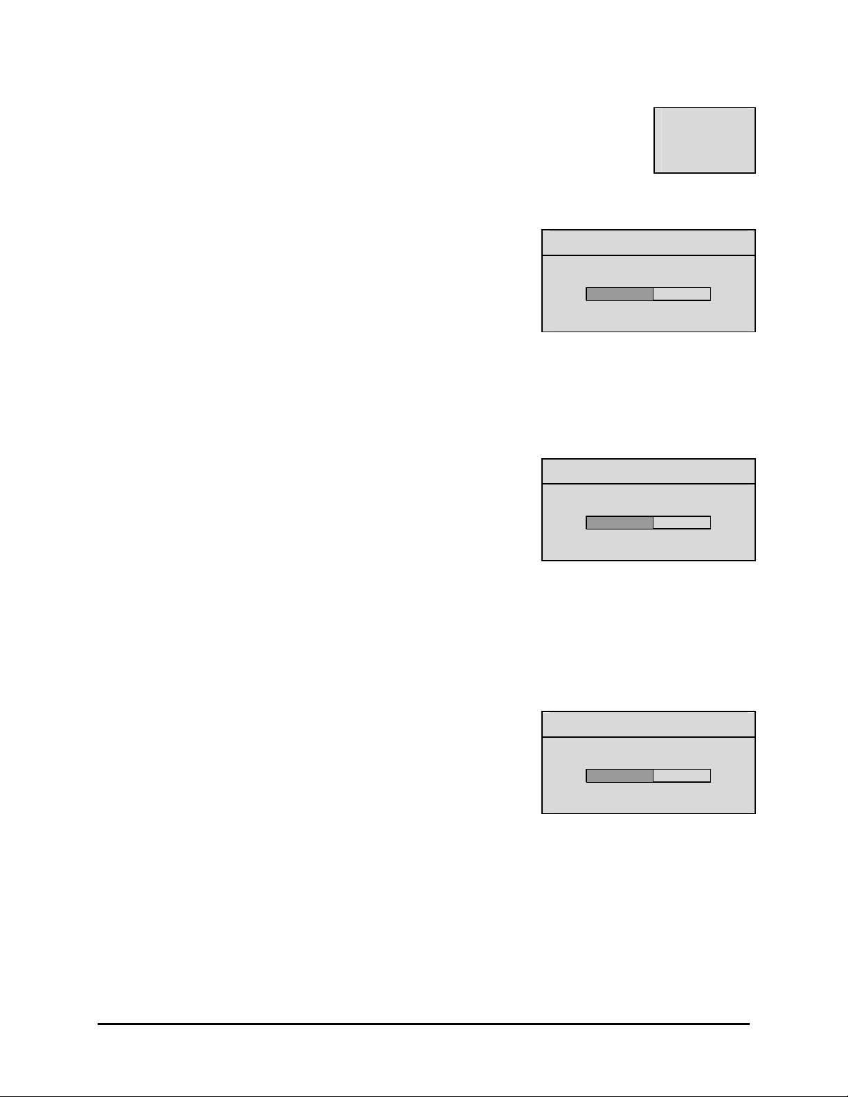
o Advanced Menu → Adjust Picture → Adjust Brightness
Use this menu to increase or decrease the brightness of the image.
Adjust Brightness
Brightness
Contrast
Saturation
1. Use the Arrow buttons to navigate to the numbers.
2. Use the Arrow buttons to increase or decrease to brightness.
3. To Save the changes and Exit the menu: Use the Arrow
buttons to select [OK], then press the Enter button.
--OR—
4. To Exit the menu without making changes: Use the Arrow
buttons to select [CANCEL], then press the Enter button.
o Advanced Menu → Adjust Picture → Adjust Contrast
Use this menu to increase or decrease the contrast of the image.
1. Use the Arrow buttons to navigate to the numbers.
2. Use the Arrow buttons to increase or decrease to contrast.
3. To Save the changes and Exit the menu: Use the Arrow
buttons to select [OK], then press the Enter button.
--OR—
4. To Exit the menu without making changes: Use the Arrow
buttons to select [CANCEL], then press the Enter button.
050
[CANCEL] [OK]
Adjust Contrast
050
[CANCEL] [OK]
o Advanced Menu → Adjust Picture → Adjust Saturation
Use this menu to increase or decrease the saturation of the image.
Saturation refers to the amount of color displayed in the image.
1. Use the Arrow buttons to navigate to the numbers.
2. Use the Arrow buttons to increase or decrease to saturation.
3. To Save the changes and Exit the menu: Use the Arrow
buttons to select [OK], then press the Enter button.
--OR—
4. To Exit the menu without making changes: Use the Arrow
buttons to select [CANCEL], then press the Enter button.
Adjust Saturation
050
[CANCEL] [OK]
Kalatel VDR 5-4 0150-0255C
Page 43

5.5 Advanced Menu → Front Panel Lock
Use this menu to Lock or Unlock the front panel.
Use the Arrow buttons to select UNLOCK KEYBOARD or LOCK KEYBOARD.
Press the Enter button to confirm the selection and exit the menu.
--OR—
Press the Menu button to exit the menu without making changes.
5.6 Advanced Menu → Factory Settings
Use this menu to enter the Factory Password, and
restore the unit to the factory defaults.
Please Enter The Factory Password
Use the Arrow buttons to select a character, then
use the Enter button to complete the selection, and
move to the next character.
Pressing the Enter button on the last character will
complete the password selection and return the unit
to the factory default configuration.
Unlock Keyboard
Lock Keyboard
Password Box
O---
5.7 Advanced Menu → Change Password
Use this menu to change the Advanced Menu
Password.
Use the Arrow buttons to select a character, then
use the Enter button to complete the selection, and
move to the next character.
Pressing the Enter button on the last character will
open the Confirmation Box.
Re-enter the New password.
Pressing the Enter button on the last character will
complete the password selection.
If the password in the Confirmation Box matches
the password from the Password box, this message
will appear.
Press the Enter button to select [OK] and exit the
menu.
The New Password Has Been Accepted!
Enter A New Password
Please Re-Enter The Password
Password Box
O---
Confirmation Box
O---
Message
[OK]
0150-0255C 5-5 Kalatel VDR
Page 44
If the password in the Confirmation Box does not
match the password from the Password box, this
message will appear.
Press the Enter button to select [OK] and exit the
menu.
The Password Was Not Changed!
Message
[OK]
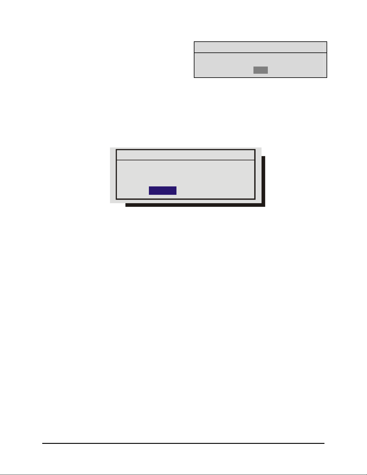
5.8 Advanced Menu → Firmware Upgrade
Use this menu to upgrade the VDR’s Firmware using a PC connected to the VDR’s Serial Port, the
upgrade file, and the WinFlash program. The following message screen will display when this
command is selected.
Firmware Upgrade
Warning! Do not power off unit
until the operation is done!
[OK]CANCEL
Use the Arrow buttons to select Cancel to exit this command or OK to proceed.
Kalatel VDR 5-6 0150-0255C
Page 45

6 RS-232 REMOTE PROTOCOL
The RS-232 protocol command structure uses “Start of Text” (Sx) and “End of Text” (Ex) characters to
identify the beginning and end of command sequences.
The VDR supports the following command sequences:
ASCII Command String
Command ASCII String Bytes in Hexadecimal
Play Forward Sx PLF Ex
Record Sx REC Ex
Stop Sx STO Ex
Pause Sx PAU Ex
Fast Forward Sx FWD Ex
Rewind Sx REW Ex
Frame Forward Sx FAD Ex
Frame Reverse Sx RAD Ex
Play Reverse Sx RPL Ex
Increase Speed Sx ISP Ex
Decrease Speed Sx DSP Ex
Search Sx SEA Ex
Up Arrow Sx ARU Ex
Down Arrow Sx ARD Ex
Left Arrow Sx ARL Ex
Right Arrow Sx ARR Ex
02 46 50 4C 03
02 52 45 43 03
02 53 54 4F 03
02 50 41 55 03
02 46 57 44 03
02 52 45 57 03
02 46 41 44 03
02 52 41 44 03
02 52 50 4C 03
02 49 53 50 03
02 44 53 50 03
02 53 45 41 03
02 41 52 55 03
02 41 52 44 03
02 41 52 4C 03
02 41 52 52 03
Menu Sx MEN Ex
Enter Sx ENT Ex
Set Clock
NOTE
Note: All byte values shown in hexadecimal.
See instructions for setting clock in the following section.
02 4D 45 4E 03
02 45 4E 54 03
0150-0255C 6-1 Kalatel VDR
Page 46

Setting the Clock
The following table shows the command sequence for setting the clock:
Command 1 2 3 4 5 6 7 8 9 10
Value
Command 11 12 13 14 15 16 17 18 19 20
Value
This gray cells in the Value row of this table indicate the correct positions for each byte of data in the
command string.
Place the hexadecimal value of the desired ASCII character into the command string. Enter a two digit
value for the Year, Month, Day, Hour, and Minute into the command string. Each digit is a separate
byte. Use the last two digits of the year for the year value (For example, 2001 is entered as 01). Time
is always designated in Military Time.
02 43 4C 4B 20
2D
d1 d2
2C
h1 h2
y1 y2
3A
2D
f1 f2
m1 m2
Example
In this example, 14:39 on December 25, 2000 is used to demonstrate the Set Clock Command String.
Year Character #1 y1
Year Character #2 y2
Notation Used in
Value Column
ASCII Character of
desired Value
0 30
0 30
Hex Value entered into
command string.
03
Month Character #1 m1
Month Character #2 m2
Day Character #1 d1
Day Character #2 d2
Hour Character #1 h1
Hour Character #2 h2
Minute Character #1 f1
Minute Character #2 f2
The final Set Clock Command String for 14:39 in December 25, 2000 would appear as follows:
Command 1 2 3 4 5 6 7 8 9 10
Value
Command 11 12 13 14 15 16 17 18 19 20
Value
02 43 4C 4B 20
2D
32 35
2C
31 34
1 31
2 32
2 32
5 35
1 31
4 34
3 33
9 39
30 30
3A
2D
33 39
31 32
03
Kalatel VDR 6-2 0150-0255C
Page 47

ASCII Status Request Messages
Command ASCII String Bytes in Hexadecimal
Model Name Request Sx MLN Ex
Software Version Number Request Sx SVN Ex
Record Mode Status Request Sx RMS Ex
Stop Mode Status Request Sx SMS Ex
ASCII Status Response Messages
Command ASCII String
Model Name Response Sx MLN VDR Ex
Software Version Number Response Sx SVN 1.18 Ex
Record Mode Status Response
Stop Mode Status Response
Sx RMS 0 E
Sx RMS 1 Ex (Recording)
Sx RMS 2 Ex (Not Recording and Disk Full)
Sx RMS 3 Ex (Recording and Disk Full)
Sx SMS 0 Ex (Not Playing)
Sx SMS 1 Ex (Playing)
Sx SMS 2 Ex (Not Playing and End of Disk)
(Not Recording)
x
02 4D 4C 4E 03
02 73 77 4E 03
02 52 4D 73 03
02 73 4D 73 03
Sx SMS 3 Ex (Playing and End of Disk)
0150-0255C 6-3 Kalatel VDR
Page 48

Page 49

7 F ACTORY DEFAULTS
Function Setting
Time Format 24 Hour
Date Format MM / DD / YY
Normal Record Speed 60 pictures per seconds (NTSC) or 50 pps (Pal)
Alarm Record Speed 60 pictures per seconds (NTSC) or 50 pps (Pal)
Record Quality High
Disk Overwrite Mode Continuous Overwrite
Auto Delete Mode Off
Front Panel Locked Off
Brightness 50%
Contrast 50%
Saturation 50%
Display Current Time and Date Off
Display Record Capacity Off
Display Last Alarm Off
Display Record or Playback Speed Off
Display Playback Time and Date Off
Baud Rate 9600
Hardwire Alarm Enabled
Alarm Buzzer Disabled
0150-0255C 7-1 Kalatel VDR
Page 50

Page 51

8 TECHNICAL SPECIFICATIONS
General
Power Supply 120-240 Volt AC, Auto-Ranging adapter
Input Voltage 12 Volt DC
Power consumption 20 Watts Max.
Operating Temperature Range Operating: 0 to 40 ºC. Storage: -20 to +60 ºC.
Relative Humidity Range (Non-Condensing) Operating: 10% to 80%. Storage: 10% to 95%
Dimensions Inches: 13 x 10.5 x 2.5, MM: 330 x 267 x 63.5
Weight 9.25 lbs. (4.20 kg)
Connections
Power Connector 2.1mm Barrel Connector, Center Positive
Accessory I/O Port DB-9 Male. See Section 1.8, Accessories Port
RS-232 Serial Port DB-9 Male DTE Connection
Composite Video In BNC connector (See caution below)
Composite Video Out BNC connector
Video
Video Signal Input 0.7 to 1.4 Volts peak-to-peak, with Automatic Gain Control
Video Signal Output 1 Volt peak-to-peak into 75-ohm
Input Termination 75-ohm
Colors Y:U:V 4:2:2, 16.8 Million Colors
Gray Scale 256 Levels
Horizontal Resolution 720 Pixels
Vertical Resolution 484 Lines
Compression Standard Wavelets
On-screen Video Indicators
End of Data
Fast Forward
Last Alarm
Record Speed
Playback Speed
Pause
Play
Record Capacity
Reverse Play
Rewind
Start of Data
Time and Date
Video Loss
0150-0255C 8-1 Kalatel VDR
Page 52

Part Numbers
User Manual 0150-0255
Approved CompactFlash Cards
Manufacturer Capacity
Fujifilm 128Mb
RCA 32Mb
PNY 128Mb
ProMaster 64Mb
Memorex 64Mb
SanDisk 64Mb
SanDisk 128Mb
SanDisk 512Mb
Lexar 4x 64Mb
Simple Tech 512Mb
All specifications are subject to change without notice. GE Interlogix believes all specifications are
correct, but no liability is assumed for omissions or errors.
Kalatel VDR 8-2 0150-0255C
Page 53

9 WARRANTY AND SERVICE
9.1 Factory Service
Warning: Do not open the top cover or attempt to service the unit, as this may expose
you to dangerous voltages and other hazards. Programmer maintenance of this unit is
limited to external cleaning and inspection. Refer all servicing to qualified personnel.
If the unit requires factory service, contact the dealer who supplied the unit to you for the correct
procedures on returning the unit to the factory or the nearest factory service center.
If the dealer is not available, contact the manufacturer of the unit as detailed below and request a
Return Material Authorization number (RMA). The unit’s serial number must be provided before a
RMA number can be issued. Units returned to the factory for service must have freight and insurance
prepaid, and must show the RMA number clearly on all shipping documents. The failure symptoms
must be clearly described by the operator and enclosed with the unit together with a copy of the
original suppliers invoice. Failure to comply with these instructions will delay service of the unit, and
may result in the unit not being accepted by the Repair Center.
Factory Address
GE Interlogix
Attention: Repair Center
3050 Redhill Ave.
Costa Mesa, CA. 92626
United States of America
Telephone: 800-343-3358 (7:00 AM to 4:30 PM, Pacific Time)
In Oregon: 541-754-9133
Fax: 541-754-7162 (24 hours a day)
For warranty information, see the following page.
0150-0255C 9-1 Kalatel VDR
Page 54

9.2 Warranty and Return Information
GE Interlogix warrants all of its equipment for three years from the date of purchase. This warranty covers
any defects in materials and workmanship. Equipment failures that are due to improper installation,
modification, abuse, or acts of nature will not be covered by this warranty. The repair department will
evaluate all equipment returned for repair to determine warranty coverage. The Tech Support Manager
will resolve any questions that may arise during evaluation to make a final determination.
Note: The three-year warranty does not apply to the following products:
MobileView® and the monitor CRT, which carry a 12-month warranty from the date of purchase.
The warranty specifically covers any defects in material and workmanship and does not cover equipment
that has been abused, damaged, or modified.
For all warranty repairs, GE Interlogix will cover all costs, including parts, labor, and shipping. Repaired
equipment will be returned via the same method of shipment in which it was received. If a customer
requests a faster return shipment, the difference will be charged.
For all non-warranty repairs, the customer will be billed for parts, labor, and shipping. Labor will be
billed in half-hour increments.
Note: Customers requesting an estimate prior to repair will be notified by phone. If they cannot be reached, they will be notified by
fax. If we are unable to reach the contact person for repair authorization after one phone attempt and two fax attempts, the
equipment will be returned without being repaired. We will hold equipment no longer than two weeks.
Advance Replacement Policy
When an advance replacement is required, we will send the customer replacement equipment from our
stock and receive the returned product in exchange. The received equipment will be evaluated and the
repair department will determine whether it is a warranty replacement. If it is non-warranty, see our repair
policy above for details. The following guidelines will be used for all advance replacements:
• Fewer than 45 days from purchase, GE Interlogix will replace the product with new equipment.
• From 45 days to 1 year from purchase, GE Interlogix will replace the product with refurbished
equipment.
• From 1 year to 3 years from purchase, the product must be sent in for repair. Advance
replacements will be sent for a fee of $100.
If you have questions about this policy, please contact the GE Interlogix RMA Department at
800-469-1676.
Kalatel VDR 9-2 0150-0255C
 Loading...