

Page 1

MM511250-11Wi-F
versions
Date
Content
Author
1.0
2016-09-01
initial release
iDatasheet
Page 2

目录
1. Introduction ........................................................................................................................... 3
1.1Module System Block Diagram ................................................................................... 4
1.2Module technical specifications ................................................................................ 4
2. Structure specification ........................................................................................................ 5
2.1 Module structure size .................................................................................................... 5
2.2 Hardware interface definition .................................................................................... 5
3. Wireless Specification ......................................................................................................... 6
Page 3

1. Introduction
MM511250-11 Wireless WIFI module is a low-power WIFI module for
the Internet of Things. It supports IEEE802.11b / g / n protocol. It also
embeds IPV4 / IPV6 TCP / IP, HTTP, DNS, FTP and other complete network
protocols, making the terminal more reliable, convenient and easy to
use.
The MM511250-11 module contains RTL8711AM single-chip solution.
the chip in software and hardware are used in low-power technology,
the purpose is to lower the power consumption of the entire board, the
product more competitive. At present, the module provides a
complete serial interface functions and equipment to communicate, so
you can through the serial port and mobile client to connect the cloud
and equipment.
IEEE 802.1b/g/n, 2.4Ghz ,1T1R
internal antennas
Green TX Low power saving technology
Low power monitor mode
Support 150Mbps
Support PWM
Full encryption support:WPS, WPA, WPA2, WAPI, WEP, TKIP
Support IPV4/IPV6, TCP/IP protocol
Support HTTP, DNS, FTP and other network protocols
Page 4
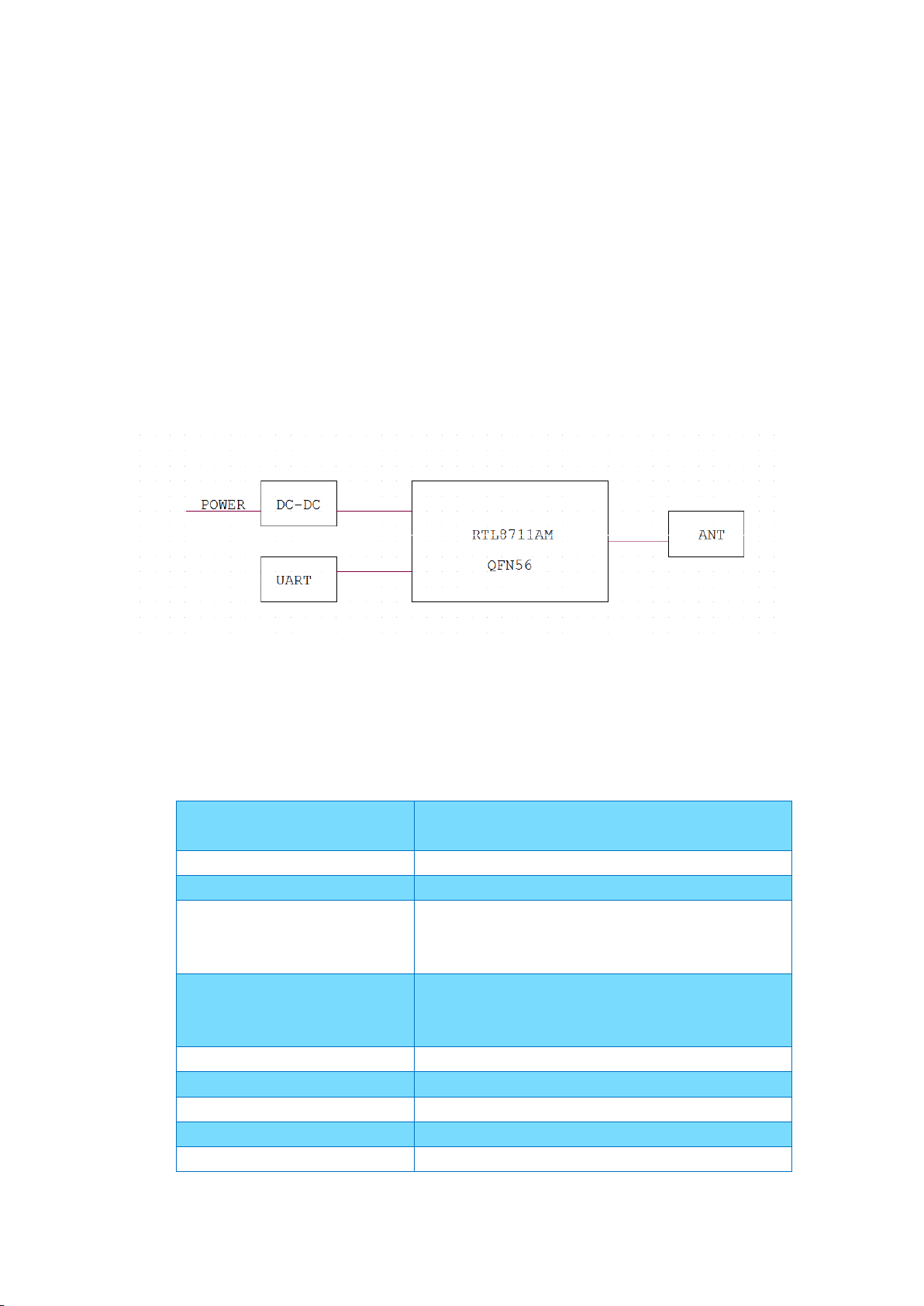
1.1Module System Block Diagram
Main chip
RTL8711AM
Workingfrequency
2.412~2.462GHz
支持的 WIFI 标准
802.11b/g/n(1x1)
Modulation
11b: DBPSK, DQPSK, CCK, DSSS
11g: BPSK, QPSK, 16QAM, OFDM
11n: MCS0~MSC7 OFDM
Supported rates
11b: 1, 2, 5.5 和 11Mbps
11g: 6,9,12,18,24,36,48,54Mbps
11n: MCS0~7, up to 150Mbps
communication interface
UART
PCB layer structure
2 Layers
PCB size
36.0mm(L)x29.0mm(W)x1.0mm(H)
Antenna
internal antennas
Working temperature
-40℃~+85℃
As shown in Figure 1,the MM511250-11 module contains
RTL8711AM single-chip solution. The module uses the internal antenna
design in PCB, both for customers to reduce the cost of the antenna,
but also eliminates the need to consider the antenna assembly space.
figure 1. Module System Block Diagram
1.2Module technical specifications
Page 5

Storage temperature
-40℃~+125℃
Hardware version
RTK-8711AM_36*29_2LVer:1.1
PIN
Signal Name
Description
1
5VDD
Supply Input Pin
2
MCU_UART_RX
UART receive data
3
MCU_UART_TX
UART transmit data
4
AGND
Ground
5,6
AGND
Ground for SMT
2. Structure specification
2.1 Module structure size
The size of the module as shown above , length:36.0mm,width:29.0mm,
thickness 1.0mm (error +/- 0.1mm)
2.2 Hardware interface definition
Page 6

3. Wireless Specification
Item
Spec
Specification
IEEE802.11b
Mode
DSSS / CCK
Channel
CH1 to CH11
Data rate
1, 2, 5.5, 11Mbps
TX Characteristics
Min.
Typ.
Max.
Unit
Remark
1. Power Levels(Calibrated)
1) 16dBm Target
14.5
16
17.5
dBm
2. Spectrum Mask @ target power
1) fc +/-11MHz to +/-22MHz
- - -30
dBr
2) fc > +/-22MHz
- - -50
dBr
3. Frequency Error
-15 0 +15
ppm RX Characteristics
Min.
Typ.
Max.
Unit
4 Minimum Input Level Sensitivity
1) 1Mbps (FER≦8%)
-
-91
-93
dBm
2) 2Mbps (FER≦8%)
-
-90
-93
dBm
3) 5.5Mbps (FER≦8%)
-
-88
-90
dBm
4) 11Mbps (FER≦8%)
-
-84
-86
dBm
5 Maximum Input Level (FER≦8%)
0 0.5
dBm
表 1: 802.11b mode
Page 7

表 2: 802.11g mode
Item
Spec
Specification
IEEE802.11g
Mode
OFDM
Channel
CH1 to CH11
Data rate
6, 9, 12, 18, 24, 36, 48, 54Mbps
TX Characteristics
Min.
Typ.
Max.
Unit
1. Power Levels
1) 12dBm Target @6Mbps
11.5
12
13.5
dBm
2) 12dBm Target @54Mbps
11.5
12
13.5
dBm
2. Spectrum Mask @ target power
1) at fc +/- 11MHz
- - -20
dBr
2) at fc +/- 20MHz
- - -28
dBr
3) at fc > +/-30MHz
- - -40
dBr
3 Constellation Error(EVM)@ target
power
1) 6Mbps
-
-22
-25
dB 2) 9Mbps
-
-22
-25
dB 3) 12Mbps
-
-23
-26
dB 4) 18Mbps
-
-24
-27
dB 5) 24Mbps
-
-24
-27
dB 6) 36Mbps
-
-27
-30
dB 7) 48Mbps
-
-28
-31
dB 8) 54Mbps
-
-30
-32
dB 4 Frequency Error
-15 0 +15
ppm
RX Characteristics
Min.
Typ.
Max.
Unit
5 Minimum Input Level Sensitivity
1) 6Mbps (PER ≦ 10%)
-
-88
-90
dBm
2) 9Mbps (PER ≦ 10%)
-
-88
-90
dBm
Page 8

3) 12Mbps (PER ≦ 10%)
-
-86
-88
dBm
4) 18Mbps (PER ≦ 10%)
-
-84
-86
dBm
5) 24Mbps (PER ≦ 10%)
-
-81
-83
dBm
6) 36Mbps (PER ≦ 10%)
-
-78
-80
dBm
7) 48Mbps (PER ≦ 10%)
-
-73
-75
dBm
8) 54Mbps (PER≦ 10%)
-
-72
-74
dBm
6 Maximum Input Level (PER ≦ 10%)
0 0.5
dBm
Item
Spec
Specification
IEEE802.11n HT20 @ 2.4GHz
Mode
OFDM
Channel
CH1 to CH11
Data rate (MCS index)
MCS0/1/2/3/4/5/6/7
TX Characteristics
Min.
Typ.
Max.
Unit
1. Power Levels
1) 12dBm Target@MCS0
11.5
12
13.5
dBm
2) 12dBm Target@MCS7
11.5
12
13.5
dBm
2. Spectrum Mask @target power
1) at fc +/- 11MHz
- - -20
dBr
2) at fc +/- 20MHz
- - -28
dBr
3) at fc > +/-30MHz
- - -45
dBr
3. Constellation Error(EVM)@ target
表 3:802.11n (HT20) mode
Page 9

power
1) MCS0
-
-22
-24
dB
2) MCS1
-
-26
-28
dB
3) MCS2
-
-26
-28
dB
4) MCS3
-
-26
-28
dB
5) MCS4
-
-26
-28
dB
6) MCS5
-
-28
-30
dB
7) MCS6
-
-28
-30
dB
8) MCS7
-
-28
-31
dB
4. Frequency Error
-15 0 +15
ppm
RX Characteristics
Min.
Typ.
Max.
Unit
5. Minimum Input Level Sensitivity
1) MCS0 (PER ≦ 10%)
-
-88
-90
dBm
2) MCS1 (PER ≦ 10%)
-
-85
-87
dBm
3) MCS2 (PER ≦ 10%)
-
-83
-85
dBm
4) MCS3 (PER ≦ 10%)
-
-80
-82
dBm
5) MCS4 (PER ≦ 10%)
-
-77
-79
dBm
6) MCS5 (PER ≦ 10%)
-
-77
-79
dBm
7) MCS6 (PER ≦ 10%)
-
-71
-73
dBm
8) MCS7 (PER ≦ 10%)
-
-69
-71
dBm
6. Maximum Input Level (PER ≦ 10%)
- 0 0.5
dBm
Page 10

表 4:802.11n (HT40) mode
Item
Spec
Specification
IEEE802.11n HT40 @ 2.4GHz
Mode
OFDM
Channel
CH3 to CH11
Data rate (MCS index)
MCS0/1/2/3/4/5/6/7
TX Characteristics
Min.
Typ.
Max.
Unit
1. Power Levels (Calibrated)
1) 12dBm Target@MCS0
11.5
12
13.5
dBm
2) 12dBm Target@MCS7
11.5
12
13.5
dBm
2. Spectrum Mask @14dBm
1) at fc +/- 22MHz
- - -20
dBr
2) at fc +/- 40MHz
- - -28
dBr
3) at fc > +/-60MHz
- - -45
dBr
3. Constellation Error(EVM)@target
power
1) MCS0
-
-26
-28
dB
2) MCS1
-
-22
-24
dB
3) MCS2
-
-22
-24
dB
4) MCS3
-
-26
-28
dB
5) MCS4
-
-26
-28
dB
6) MCS5
-
-26
-28
dB
Page 11

7) MCS6
-
-27
-29
dB
8) MCS7
-
-29
-31
dB
4. Frequency Error
-15 0 +15
ppm
RX Characteristics
Min.
Typ.
Max.
Unit
5. Minimum Input Level Sensitivity
1) MCS0 (PER ≦ 10%)
-
-86
-88
dBm
2) MCS1 (PER ≦ 10%)
-
-83
-85
dBm
3) MCS2 (PER ≦ 10%)
-
-81
-83
dBm
4) MCS3 (PER ≦ 10%)
-
-77
-79
dBm
5) MCS4 (PER ≦ 10%)
-
-74
-76
dBm
6) MCS5 (PER ≦ 10%)
-
-69
-71
dBm
7) MCS6 (PER ≦ 10%)
-
-69
-71
dBm
8) MCS7 (PER ≦ 10%)
-
-67
-69
dBm
6. Maximum Input Level (PER ≦ 10%)
- 0 0.5
dBm
Page 12

FCC Statement
This device complies with part 15 of the FCC rules. Operation is subject to the
following two conditions: (1) this device may not cause harmful interference, and (2)
this device must accept any interference received, including interference that may
cause undesired operation.
Changes or modifications not expressly approved by the party responsible for
compliance could void the user’s authority to operate the equipment.
NOTE: this equipment has been tested and found to comply with the limits for a Class
B digital device, pursuant to part 15 of the FCC Rules. These limits are designed to
provide reasonable protection against harmful interference in a residential
installation. This equipment generates uses and can radiate radio frequency energy
and, if not installed and used in accordance with the instructions, may cause harmful
interference to radio communications. However, there is no guarantee that
interference will not occur in a particular installation. If this equipment does cause
harmful interference to radio or television reception, which can be determined by
turning the equipment off and on, the user is encouraged to try to correct the
interference by one or more of the following measures:
● Reorient of relocate the receiving antenna.
● Increase the separation between the equipment and receiver.
● Connect the equipment into an outlet on a circuit difference from that to which
the receiver is connected.
● Consult the dealer or an experienced radio/TV technician for help.
Important Note:
Radiation Exposure Statement
This equipment complies with FCC radiation exposure limits set forth for an
uncontrolled environment. This equipment should be installed and operated with
minimum distance 20 cm between the radiator and your body.
This transmitter must not be co-located or operating in conjunction with any other
antenna or transmitter.
Country Code selection feature to be disabled for products marketed to the
US/Canada.
1. The antenna must be installed such that 20 cm is maintained between the
antenna and users, and
2. The transmitter module may not be co-located with any other transmitter or
antenna.
As long as the three conditions above are met, further transmitter testing will not be
required. However, the OEM integrator is still responsible for testing their
end-product for any additional compliance requirements required with this module
installed.
Page 13

Important Note:
In the event that these conditions cannot be met (for example certain laptop
configurations or co-location with another transmitter), then the FCC authorization is
no longer considered valid and the FCC ID cannot be used on the final product. In
these circumstances, the OEM integrator will be responsible for re-evaluating the
end product (including the transmitter) and obtaining a separate FCC authorization.
End Product Labeling:
The final end product must be labeled in a visible area with the following “Contains
FCC ID: 2ADQOMDWF01”
If the FCC identification number is not visible when the module is installed inside
another device, then the outside of the device into which the module is installed
must also display a label referring to the enclosed module. This exterior label can use
wording such as the following; Contains Transmitter Module FCC ID:
2ADQOMDWF01.
Manual Information to the End User:
The OEM integrator has to be aware not provide information to the end user
regarding how to install or remove this RF module in the user’s manual of the end
product which integrates this module.
The end user manual shall include all required regulatory information/warning as
show in this manual.
When the module is installed inside another device, the user manual of this device
must contain below warning statements;
1. This device complies with part 15 of the FCC rules. Operation is subject to the
following two conditions:
1) this device may not cause harmful interference,
2) this device must accept any interference received, including
interference that may cause undesired operation.
2. Changes or modifications not expressly approved by the party responsible for
compliance could void the user’s authority to operate the equipment. The
devices must be installed and used in strict accordance with the
manufacturer’s instructions as described in the user documentation that
comes with the product.
 Loading...