


NT 200R-PLUS
ADSL Modem/Router
User Guide
GDI COMMUNICATIONS LLC.,
PO Box 1330, Verdi NV 89439

WARRANTY
GDI Communications LLC. warrants to the original consumer purchaser that each of its
hardware products, and all components thereof, will be free from defects in
materials and/or workmanship for one (1) year from the date of original purchase
and is not assignable.
In the event of malfunction or other indications of failure attributed directly to faulty
workmanship and/or materials, GDI Communications LLC. will, at its option, repair or
replace the defective products or components to whatever extent it shall deem
necessary to restore the product or components to proper operating condition,
provided the consumer purchaser sends with the defective product proof of the
date of purchase of the product. Please note that GDI Communications LLC. may
replace the defective product with a new or re manufactured functionally equivalent
product of equal value at the option of GDI Communications LLC.
The customer shall be solely responsible for the failure of any Extreme Copper,
Inc. computer product, or component thereof, resulting from accident, abuse, or
misapplication of the product, and GDI Communications LLC. assumes no liability as a
consequence of such events under the terms of this Warranty.
GDI Communications LLC. does not warrant the merchantability or fitness of this product
for any particular purpose. This limited warranty is in lieu of any and all other
warranties, expressed or implied.
GDI Communications LLC.'s liability shall not exceed the price of the defective individual
product, which is the basis for claim. In no event will GDI Communications LLC. be
liable for direct, indirect, incidental, or consequential damages resulting from any
defect in the product or in this manual, even if they have been advised of the
possibility of such damages. In no event shall GDI Communications LLC. be liable for
any loss of profits, loss of equipment or facilities, or the loss of programs or data, or
the cost of recovering or reproducing the program or data. Some states do not
allow the exclusions or limitation of implied warranties or liability for incidental or
consequential damages, so the above limitations or exclusion may not apply to
you.
2

TABLE OF CONTENTS
GENERAL INFORMATION ....................................................4
FEATURES .........................................................................4
INSTALLATION......................................................................5
CONNECTING TO THE A DSL LINE INTERFACE .............6
CONNECTING THE LAN (ETHERNET) INTER FACE........7
CONNECTING POWER......................................................8
OPERATION...........................................................................9
POWER UP.........................................................................9
FRONT PANEL LED STATUS MONITORS .......................9
CONFIGURING FOR INTERNET CONNECTION ................11
SETTING UP YOUR PC....................................................11
WAN CONFIGURATION: .................................................13
LAN CONFIGURATION:...................................................14
VPN CONFIGURATION:...................................................15
SAVING YOUR CONFIGURA TION: .................................16
CUSTOMER SERVICE .....................................................17
SERVICE AND UNRESOLVED PROBLEMS...................17
APPENDIX A ............................................ ............................18
SPECIFICATIONS ............................................................18
APPENDIX B ........................................................................20
INTERFACE PIN ASSIGNMENT ......................................20
3

GENERAL INFORMATION
Thank you for purchasing this GDI Communications LLC. product. The NT200R-PLUS
provides reliable, high-speed, Internet access to your existing phone line. There is
no special wiring or special networking knowledge required. This modem is
capable of data rates hundreds of times faster than a traditional analog modem.
Unlike the analog modem, the NT200R-PLUS allows you to use your phone line for
simultaneous voice/fax and high-speed communications, eliminating the need for
dedicated phone lines for voice and data communications. The NT200R-PLUS
provides reliable high-speed data communication in the harshest operating
environments. It can operate in uncontrolled environments such as remote
terminals or curb side distribution vaults. Installation is easy ... no tools ... no
headaches. Simply connect the hardware and apply power.
Designed to operate in the harshest environments the NT200R-PLUS has an
operating temperature range of -37°C to +74°C, in non-condensing humidity of up
to 95%, and can be set up at altitudes of up to 10,000 feet.
This manual has been designed to enable you to install your NT200R-PLUS modem
by following the step-by-step installation procedure.
FEATURES
Easy to install standalone ADSL modems
Environmentally hardened for operation in harsh environments
Auto-sensing full or half-duplex Ethernet
Auto-sensing 10/100 operation
Transparent operation
LED indicators for Power, Ethernet Link & Activity, ADSL Sync
4
INSTALLATION
Because the NT200R-PLUS requires minimum configuration, it can be installed and
made operational quickly. Installation takes place as follows:
1. Connecting the ADSL line (refer to section titled, “Connecting the ADSL Line
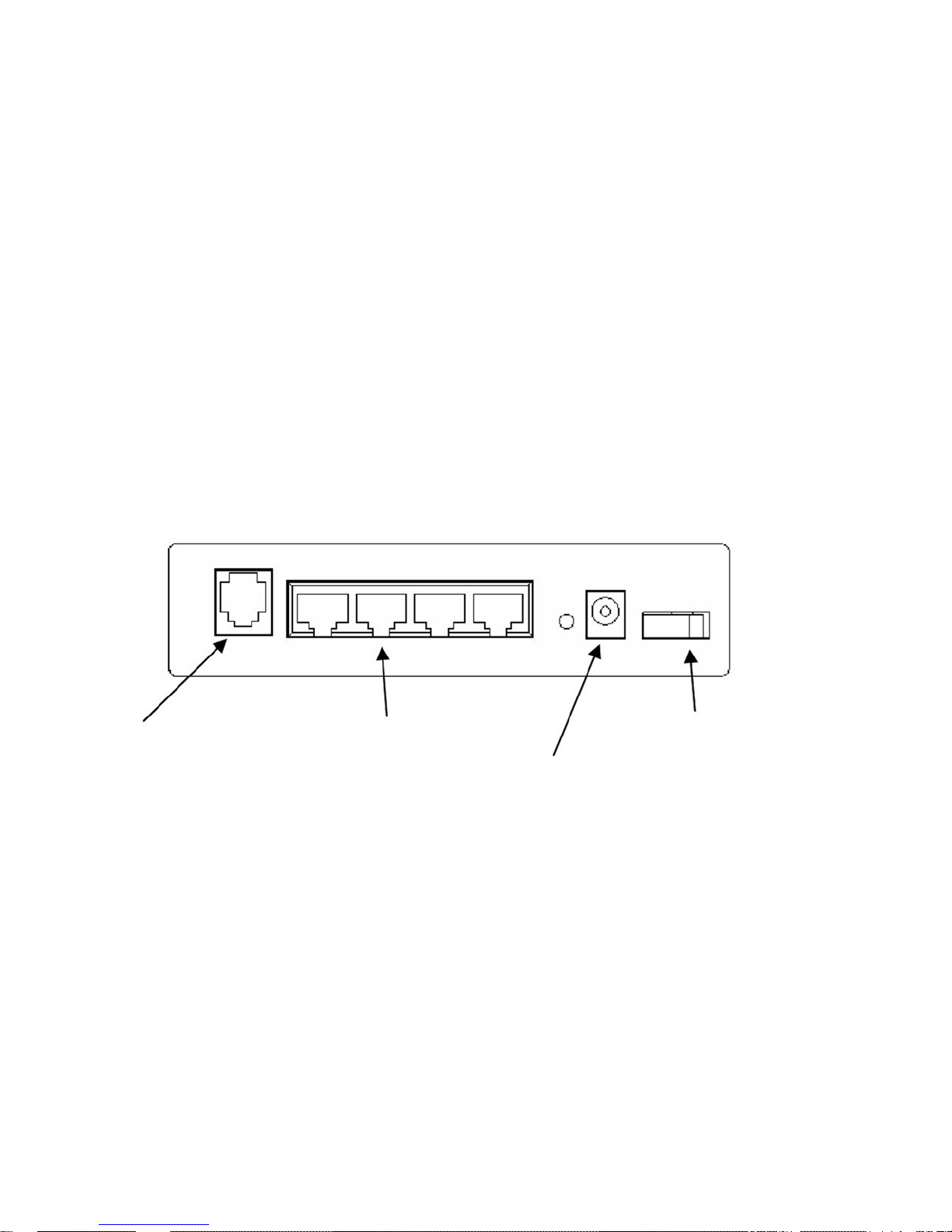
Interface” on page 6) See Figure 4 for the rear panel connector arrangements.
2. Connecting the Ethernet interface (refer to section titled, “Connecting the LAN
(10/100Base-T) Ethernet Interface” on page 7).
3. Connecting the power plug (refer to section titled, “Connecting Power” on
page 8).
NT200R-PLUS
ADSL Line
4 Ports of
Ethernet Access
ON / OFF Switch
Power Jack
Figure 1.
NT200R-PLUS standalone rear panel
5
CONNECTING TO THE ADSL LINE INTERFACE
The NT200R-PLUS supports High-speed communications over 24 AWG (0.5 mm)
twisted-pair wire. Actual distance and link perform ance ma y va ry depending on the
environment and type or gauge of wire used.
Follow the steps below to connect the NT200R-PLUS ADSL Interface to the DSL
ready telephone line. Connect a telephone phone cable from the DSL-equipped
telephone line jack to the jack marked DSL on the rear panel of the modem.
To function properly, the NT200R-PLUS must be connected to the telephone line
using twisted-pair wire between 19 (0.9mm) and 26 AWG (0.4mm). The interface is
bipolar making the TIP and RING connection non-critical.
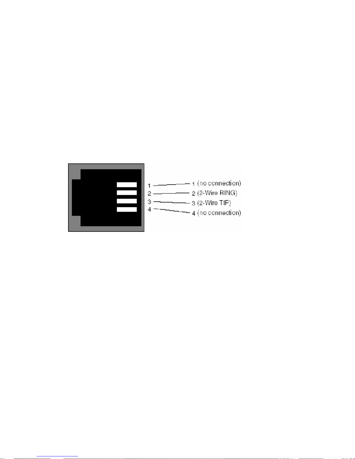
The diagram below shows the pin configuration of the ADSL jack on the NT200R
Plus.
Figure 2.
NT 200(RJ11) ADSL line interface.
6
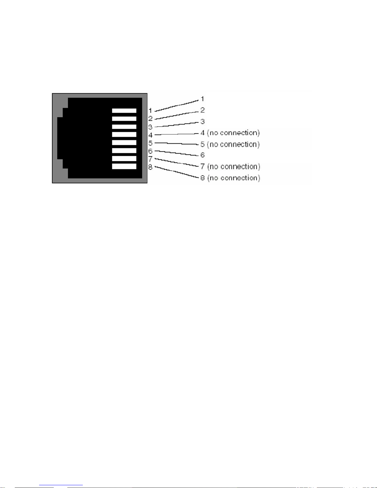
CONNECTING THE LAN (ETHERNET) I NTE RFACE
The RJ-45 ports are labeled “LAN”, 1 through 4. These ports are designed to
connect directly to a 10/100BaseT/TX network. Figure 3 shows the signal/pin
relationships on this interface. You may connect these ports to another Ethernet
device via a Cat 3 or Cat 5 cable that is up to 328 ft long.
RX+ (data input to NT200R-PLUS)
RX- (data input to NT200R-PLUS)
TX+ (data output from NT200R-PLUS)
TX- (data output from NT200R-PLUS)
Figure 3.
NT200R-PLUS LAN (10/100BaseT/TX) RJ-45 Connector Pin out.
NOTE: Before you connect via 10/100 Base-T, you must have an available
Ethernet card installed in your computer. If your Ethernet card does not autonegotiate, you must set it to half duplex. Refer to the Ethernet card
manufacturer’s instructions for installing and configuring your Ethernet card.
Connecting the LAN (10/100BaseT/TX) Ethernet Port to a Hub
The NT200R-PLUS LAN interface is configured as DCE (Data Communications
Equipment), just like a 10/100BaseT/TX network hub or a switch. Therefore, it
"expects" to connect to a DTE (Data Terminal Equipment) device such as a PC or
a router. When connecting to a DTE it typically uses a straight through cable as
shown in figure 4 below.
NT 200 (NT) LAN (10/100BaseT/TX) Port
RJ-45 Pin No.
10/100BaseT/TX Hub
RJ-45 Pin No.
(RX+) 1 ------------------------------------------------- 1 (TX+)
(RX-) 2 ------------------------------------------------- 2 (TX-)
(TX+) 3 ------------------------------------------------- 3 (RX+)
(TX-) 6 ------------------------------------------------- 6 (RX-)
Figure 4.
10/100BaseT/TX straight through cable
7

CONNECTING POWER
An external AC cube style power supply is available. Power to the NT200R-PLUS is
connected using the barrel jack on the rear panel. No configuration is necessary for
the power supply. AC power supplied must meet the following requirements;
12DC, 1A. The barrel type plug has a 2.5/5.5/10mm I.D./O.D./Shaft Length
dimensions.
8

OPERATION
Once the NT200R-PLUS is properly installed, the set should operate transparently.
This section describes the LED status monitors.
POWER UP
Before applying power to the NT200R-PLUS, please review section titled,
“Connecting Power” to verify that the unit is connected to the appropriate power
source.
FRONT PANEL LED STATUS MONITORS
The NT200R-PLUS features six front panel LEDs that monitor power, the ADSL
Connection and the Ethernet connections. Figure 5 shows the front panel location
of these displays. Table 1 describes the LED functions.
NT200R-PLUS
Power
ADSL Link
Ethernet
(DSL)
(LAN)
Figure 5.
NT200R-PLUS Front panel LED location
9
(PWR)

DSL
LED Description NT200R-PLUS
LED
Indication
Power
Steady GREEN to indicate the unit is powered ON.
No Light No Power.
RED resetting or problem state.
Slow Flashing Green Power ON and Waiting for carrier
detect signal (1 flash/sec)
Moderate Flashing Green Power ON and attempting
synchronization (2 flashes/sec)
Steady green (ON) to indicate that the ADSL link is
established.
LAN PORTS
Steady Green Ethernet link has been established.
Flashing Green Transmit or Receive Activity.
No Light No Ethernet link established.
Table 1:
Front panel LED description
10

CONFIGURING FOR INTERNET CONNECTIO N
To browse the Internet using your NT200R-PLUS, you must set up your router
access, confirm your DSL sync, and establish a PPP session with your Internet
service provider (ISP).
SETTING UP YOUR PC
Configure your computer to use an IP address on the same TCP/IP network as
your router.
For Windows XP;
Right click on the Network Neighborhood icon, in the drop down dialog box click on
Properties.
Select your Local Area Connection; right click on your Local Area Connection, in
the drop down dialog box click on Properties.
A Network Connection dialog box will appear. Scroll down to Internet Protocol
[TCP/IP].
Click on the Properties button.
The Internet Protocol (TCP/IP) properties dialog box will appear. On the General
TAB, select Obtain an IP address automatically and below that select Obtain DNS
server address automatically.
Click on the OK button and proceed to configure your router.
Load the Router Management software. Double on the ecmanagement.exe
Right click on Management.exe file and select Send to Desktop (Create a
shortcut). Windows XP will place a shortcut on your desktop.
At your desktop double click on the management shortcut icon
The Host Settings dialog box will open.
Enter the IP address and port number of the router you are going to configure.
Click on Connect Now button
NOTE: The default IP address for a new router is “192.168.1.1” and the port is 23
The Router Management screen will appear.
11

Click on Refresh Config button.
The router information will appear in all the fields in all tabs.
12

WAN CONFIGURATION:
This information is for the network on the ISP or DSL side of the router.
• Select the WAN Tab;
• Select the circuit type for your installation.
Multimode
T1.413
G.DMT
G.Lite
ADSL2
ADSL2+
ReADSL2
• Select the Data Link Encapsulation for your installation
RFC1483
PPP
• In the Circuit Name box fill in a name for your circuit
• Enable your circuit by selecting YES from the dropdown menu
• Select the Circuit VPI and VCI. The default numbers are typical for most
applications.
• Select the Quality of Service (QoS) for your installation. UBR is typical.
• Change Peak Cell Rate as required; 0 equals your Line Rate.
Click on the Save Change button. The software will restart
A YES/NO dialog will appear and it will tell you the router will reset if you select
YES.
Click on the Refresh Config button .
Verify the changes are complete.
13

LAN CONFIGURATION:
This is the information for the network on the user side of the router.
• Select the LAN Tab;
NOTE: All addresses and subnet masks a re entered in Dotted Decimal format
xxx.xxx.xxx.xxx
• Enter the router LAN IP address.
• Enter the router LAN subnet mask
• Enter the router LAN default IP Gateway address
(This can be the address of any major gateway accessible to the Router.)
• Enter the Domain Names for your network
• Select the IP address server mode
If this router will not be a server select Disable
If this router will be assigning IP address for you network select DHCP Server.
If this router will be relaying addresses select DHCP relay agent,
DHCP Server information
This is where the information for the DHCP IP address pool will be established.
• Enter IP address for the first IP client on your network in the IP Range Start
box.
• Enter IP address for the last IP client on you network in the IP Range Stop box.
• Enter the IP address of the Gateway .
NOTE: If this is the router IP address you will need to make the IP Range Start
address one less than router IP address.
• Enter the Domain Names for your network.
Click on Save Changes button. The software will restart.
A YES/NO dialog will appear and it will tell you the router will reset if you select
YES.
If you are sure of the information click on YES.
14

VPN CONFIGURATION:
If you are setting up a Virtual Private Network (VPN) you will need to use this tab.
• Select VPN Tab;
• Enable VPN operation by selecting YES in the VPN Enable box.
• Enter a name for your VPN.
• In the Remote Gateway IP box Enter the WAN IP address of the remote router.
• Enter a key phrase you will remember in Pre Shared Key. This key will need to
be entered in the remote router.
• Enter the Encryption Algorithm to be used in this VPN the options are
DES
3DES
• Enter the Hash Algorithm to be used in this VPN the options are
MD5
SHA1
Under Phase 2/Connection Profile
• Enter the Local IP address of this router. This is the network address for this
router.
• Enter the Local IP Subnet mask. This is the subnet mask for this router
• Enter the Remote Internal Router IP address this is the Ethernet address for the
remote router.
• Enter the Remote IP address. This is the Ethernet network address for the
remote router
• Enter the Remote Subnet mask. This is the remote router Ethernet network
subnet mask.
Click on Save Changes
A YES/NO dialog will appear and it will tell you the router will reset if you select
YES.
If you are sure of the information click on YES.
15

SAVING YOUR CONFIGURATION:
All configuration changes are staged in the router and will only be applied by
restarting the router.
After clicking on the Save Changes button the dialog boxes below will be
displayed.
If you are sure of the changes you have made click on Yes.
Click OK
The warning screen message below will appear.
When you are ready for your changes to be applied,
Click on Tools in the Menu Bar.
Click on Restart Router.
The router will restart; all changes will be applied.
16

CUSTOMER SERVICE
SERVICE AND UNRESOLVED PROBLEMS
For assistance, phone GDI Communications’s Customer Service Department between
7:00 A.M. and 3:30 P.M. Pacific Time at (775) 345-8000 or FAX (775) 345-8010.
When calling for assistance try to do so from the installation site, we have a better
chance to successfully troubleshoot your installation and getting your installation
up and running.
Before returning a product for repair, you must call GDI Communications’s Customer
Service Department and receive a Returned Material Authorization (RMA) number.
This number must appear on the outside of the shipping container with the address
as indicated below. Products should be returned to:
GDI COMMUNICATIONS LLC., 280 I-80 West, Exit 1, Verdi NV 89439
Attention: Customer Service-RMA #
To ensure accurate return of repaired/replaced product, please enclose a note with
the returned item; with your name, company name, mailing address, telephone
number, RMA number and any special instructions.
During the first year after the date of purchase, all labor and materials will be
provided without charge. There shall be no warranty for either parts or labor after
the expiration of one year from the date of purchase or if in Extreme Copper’s sole
discretion the product has been deemed to be modified or abused.
Units must be returned postage prepaid, CODs will not be accepted! It is
recommended that the unit be insured when shipped. Units returned without proof
of date-of-purchase or out-of-warranty units will be repaired or replaced (at the
option of Extreme Copper) and a charge will be made for parts and labor.
Products repaired/replaced under warranty will be returned to any destination
within the USA at GDI Communications’s expense. The carrier and method of shipment
will be determined by GDI Communications LLC.
If the customer requests a specific form of conveyance or is located beyond the
USA borders or if the unit is out-of-warranty, all shipping costs will be incurred by
the customer.
17

APPENDIX A
SPECIFICATIONS
CONNECTORS
LAN: Shielded or Unshielded RJ-45, 10/100Base-T, IEEE 802.3 Ethernet
ADSL: RJ 11
Power Jack
ADSL ENVIRONMENT
LINE: 19 to 26 AWG (0.5 mm) twisted-pair wire
LED INDICATORS
Power (Green)
DSL Sync (Green)
LAN, Ethernet Good Link (Green/Red/Amber)
POWER SUPPLY
External AC power cube input 112 VAC, 47 to 63Hz, >6 Watt
+12.0 Output
OPERATING ENVIRONMENT
TEMPERATURE RANGE: -37°C to +74°C
HUMIDITY: Up to 95% non-condensing
DIMENSIONS
1.25H x 5.3W x 5.3D in. (3.68H x 12.19W x 12.37D cm)
MOUNTING
Standalone metal enclosure
18

APPROVALS
FCC NOTICE
The NT 200 generates and uses radio frequency energy, and if not properly
installed and used in strict accordance with the manufacturer’s instructions it may
cause interference to radio and television reception. The NT 200 has been tested
and found to comply with Class B computing device in accordance with
specifications in Subpart B of Part 15 of FCC rules. However, there is no guarantee
that interference will not occur in a particular installation.
19

APPENDIX B
INTERFACE PIN ASSIGNMENT
LAN (ETHERNET 10/100BASET/TX) INTERFACE: RJ-45 UTP/STP
Pin 1: RX+
Pin 2: RXPin 3: TX+
Pin 6: TXPins 4, 5, 7, 8: no connection
Shield: Bat Com (STP only)
ADSL LINE INTERFACE: RJ-11
Pin 2: RING
Pin 3: TIP
Pins 1, 4: no connection
20

Copyright © 2011
GDI Communications LLC.
All Rights Reserved.
21
 Loading...