

GDI Halo Product Manual

Halo
802.11 a Outdoor AP
Product Manual
January 2007, Version 1.11

Notice
The changes or modifications not expressly approved by the party responsible for
compliance could void the user’s authority to operate the equipment.
IMPORTANT NOTE
To comply with the FCC RF exposure compliance requirements, no change to the
antenna or the device is permitted. Any change to the antenna or the device could
result in the device exceeding the RF exposure requirements and void user’s authority
to operate the device.
FCC Notice
This equipment has been tested and found to comply with the limits for a Class B digital
device, pursuant to Part 15 of the FCC Rules. These limits are designed to provide
reasonable protection against harmful interference in a residential installation. This
equipment generates, uses, and can radiate radio frequen cy energy and, if not installed
and used in accordance with the instructions, may cause harmful interference to radio
communications. However, there is no guarantee that interference will not occur in a
particular installation. If this equipment does cause harmful interference to radio or
television reception, which can be determined by turning the equipment off and on, the
user is encouraged to try to corr ect the interference by one or more of the followin g
measures:
• Reorient or relocate the receiving antenna.
• Increase the separation between the equipment and receiver.
• Connect the equipment into an outlet on a circuit different from that to which the
receiver is connected.
• Consult the dealer or an experienced radio tech nician for help.
Changes or modifications not expressly approved in writing by Wireless Interactive Comm.
Inc. may void the user’s authority to oper ate this equipment. Wireless Interactive Comm.
Inc. can not accept any financial or other responsibilities that may be the result of your use
of this information, including dir ect, indirect, special, or consequential d amages. Refer to
warranty documents for product warranty coverage and specifics.
2

Table of Contents
CHAPTER 1. INTRODUCTION ................................................................................................................ 5
1-1 O
1-2 K
1-3 W
1-4 S
1-5 H
1-6 H
CHAPTER 2. ANTENNA AND RF TUTORIAL ..................................................................................... 17
CHAPTER 3. BASIC INSTALLATION AND SECURITY..................................................................... 24
3-1 D
3-2 W
3-3 I
CHAPTER 4. GENERAL INFORMATIO N ............................................................................................. 2 8
4-1 I
4-2 C
CHAPTER 5. ADDED FUNCTIONALITIE S .......................................................................................... 32
5-1 T
5-2 B
5-3 A
5-4 U
5-5 HTTP R
5-6 F
5-7 V
CHAPTER 6. WIRELESS SETUP .......................................................................................................... 41
6-1 B
6-2 VAP / VLAN S
6-3 U
6-4 A
6-5 WDS M
6-6 S
6-7 A
CHAPTER 7. MANAGING AND T ESTING Y OUR A P ........................................................................ 52
7-1 S
7-2 L
CHAPTER 8. MANAGEMENT ........................................................................................................................ 54
VERVIEW ...................................................................................................................................................................... 5
EY FEATURES .............................................................................................................................................................. 6
ARNINGS ...................................................................................................................................................................... 8
YSTEM REQUIREMENTS .......................................................................................................................................... 10
ARDWARE DESCRIPTION ........................................................................................................................................ 11
ARDWARE INSTALLATION ....................................................................................................................................... 14
EFAULT FACTORY SETTINGS ................................................................................................................................ 24
IRELESS SECURITY OPTIONS .............................................................................................................................. 25
NSTALLING THE RADIO AS AN AP (ACCESS POINT) ........................................................................................... 26
NFORMATION .............................................................................................................................................................. 28
ONNECTION ............................................................................................................................................................... 30
IME SERVER .............................................................................................................................................................. 32
RIDGE/ROUTER MODE ........................................................................................................................................... 33
NY IP .............................................. ...... ....... ...... ....... ...... ......... ....... ...... ....... ...... ....... .... ................... 34
NDERSTANDING RADIUS SETTINGS ................................................................................................................. 35
EDIRECT ....................................................................................................................................................... 36
IREWALL MANAGEMENT................................................................................................................................................... 37
IRTUAL SERVER ....................................................................................................................................................... 39
ASIC SETTINGS ........................................................................................................................................................ 41
ETTINGS ................................................................................................................................................... 42
NDERSTANDING WEP/WPA SECURITY OPTIONS .......................................................................................... 45
CCESS CONTROL .............................................................................................................................................................. 48
ODE ........................................................................................................................................................................ 48
MART WDS ........................................... ............................. ............................ ....................... ........... 49
DVANCED SETTINGS ........................................................................................................................................................ 49
ITE SURVEY .............................................................................................................................................................. 52
INK TEST .................................................................................................................................................................... 53
8-1 C
8-2 R
8-3 U
8-4 B
8-5 E
8-6 R
HANGE PASSWORD ................................................................................................................................................. 54
EMOTE MANAGEMENT ..................................................................................................................................................... 55
PGRADE FIRMWARE ................................................................................................................................................ 58
ACKUP / RESTORE SETTINGS ............................................................................................................................... 59
VENT LOG ................................................................................................................................................................. 60
EBOOT AP ........................................................................................................................................ 61
CHAPTER 9. TR OUBLE SHOOTING ..................................................................................................... 62
9-1 G
9-2 C
9-3 C
9-4 C
ENERAL DESCRIPTIONS ......................................................................................................................................... 62
ONNECTION ISSUES ................................................................................................................................................ 63
ONFIGURATION ISSUES .......................................................................................................................................... 64
OMMUNICATION ISSUES ......................................................................................................................................... 64
3

Copyright
This user’s manual and the software described in it are copyrighted with all rights reserved.
No part of this publication may be reproduced, transmitted, transcribed, stored in a
retrieval system, or translated into any language in any form by any means without the
written permission of the Wireless Interactive.
Preface
About This Manual
This manual explains proper installation of the Halo series radios.
Document Conventions
This publication uses the following conventions to convey instructions and information:
STA refers to a station
ETH refers to a PC
This symbol means reader take note. Notes contain helpful suggestions or
references to materials not contained in this manual.
This symbol means reader be careful. In this situation, you might do something
that could result in equipment damage or loss of data.
This warning symbol means danger. You are in a situation that could cause bodily
injury. Before you work on any equipment, be aware of the hazards involved with
electrical circuitry and be familiar with standard practices for preventing accidents.
Bold: Emphasizes critical functions and explanations.
4

Chapter 1. Introduction
Thank you for choosing this Enterprise-class outdoor radio (hereafter called radio). This
radio provides a secure, affordable, and easy-to-use wireless LAN solution that combines
mobility and flexibility with the enterprise-class features required by networking
professionals.
This chapter gives an overview of the enterprises-class radio, as well as its key features.
In addition, we detail about the hardware descriptions, system requirements and basic
installation.
1-1 Overview
802.11a-compliant, VLAN functionality allows a single network AP to behave as “8”
number of virtual network APs. This does away with the limitation by the sheer number of
Ethernet connections that need APs acting as a proxy. WMM prioritizes traf fic demands
from different applications and extends Wi-Fi’s high quality end-user experience from data
connectivity to voice, music, and video applications under a wide variety of en vironment.
This Access points serves as the connection point between wirele ss and wired networks
or as the center point of a stand-alone wireless network. In large installations, wireless
users within radio range of an access point can roam throughout a facility while
maintaining seamless, uninterrupted access to the network.
You can configure and monitor the radio using the command-line interface (CLI), the
browser-based management system, or Simple Network Management Protocol (SNMP).
This radio currently can support data rate up to 108Mbps.
Use the instructions in this Guide to help you connect the outdoor radio, set it up, and
configure it to bridge your different networks. These instructions should be all you need to
get the most out of the radio
5

1-2 Key Features
The radio is user-friendly and provides solid wireless and networking support. The
following standards and conventions are supported:
• Standards Compliant
The Wireless Access Point complies with the IEEE 802.11a for Wireless LANs.
• WEP support
Support for WEP is included. 64-bit, 128-bit, and 152-bit keys.
• DHCP Client Support
DHCP Server provides a dynamic IP address to PCs and other devices upon request. The
radio can act as a client and obtain information from your DHPC server.
• RADIUS Accounting
Enable accounting on the access point to send accounting data about wireless client
devices to a RADIUS server on your network.
• SNMP Support
Support for Simple Network Management Protocol (SNMP) Management Information
Base (MIB) management.
• Multiple operating modes
1. Access point
2. Station Adapter
3. Point-to-Point Bridge.
4. Wireless Repeater
5. Inter-building
• Repeater mode
Configure the radio as a wireless repeater to extend the coverage area of your wireless
network.
• VAPs (VLAN)
Assign Multi-SSIDs on your radio (one SSID per VAP) to differentiate policies and
services among users forming a wide variety of VLANs.
• QoS
Use this feature to support quality of service for pri oritizi ng traffic from the Ethernet to the
access point.
• Wi-Fi Multi-media (WMM)
Radio also supports the voice-prioritization schemes by using the 802.11a wireless
phones via enable the WMM application.
•
Transmit Power Control
Supports settable transmit power levels to adjust coverage cell size, ranging from full,
half(50%), quarter(25%) eighth(12.5%) and min
6

•
Atheros Super G Mode
Super G mode enables the transmission up to 108Mbps
• Multiple security settings per VLAN with up to 8 VLANs
Security settings for multiple groups; so employees, guests and contractors now easily
and securely share the same infrastructure
•
Access Control
The Access Control MAC address filtering feature can ensure that only trusted wireless
stations can use the radio to gain access to your LAN.
•
Hidden Mode
The SSID is not broadcasted; ass uring only cli ents c onfig ur ed wi th t he co rrec t SSID c an
connect.
7

1-3 Warnings
y
y
g
y
g
In order to comply with international radio frequency (RF) exposure limits,
dish antennas should be laced at a minimum of 8.7 inches (22 cm) from the
bodies of
(20 cm) from the bodies of
Do not work on the system or connect or disconnect cables during periods of
lightning activity.
This equipment must be grounded. Never defeat the ground conductor or
operate the equipment in the absence of a suitabl
conductor. Contact the appropriate electrical inspection authorit
electrician if you are uncertain that suitable grounding is available.
Ultimate disposal of this product should be handled according to
laws and regulations.
persons. Other antennas should be laced a minimum of 7.9 inches
all
persons.
all
installed ground
or an
national
all
Do not locate the antenna near overhead power lines or other electric light or
power circuits, or where it can come into contact with such circuits. When
installin
circuits, as the
and
the antenna, take extreme care not to come into contact with such
may cause serious injury or death. For proper installation
rounding of the antenna, please refer to national and local codes (e.g.
U.S.:NFPA 70, National Electrical Code, Article 810, in Canada: Canadian
Electrical Code, Section 54).
Only trained and qualified personnel should be allowed to install, replace, or
service this equipment.
8

g
g
y
To meet regulatory restrictions, the radio and the external antenna must be
professionally installed. The network administrator or other IT professional
responsible for installin
installer. Followin
protected by the network administrator to maintain regulatory compliance.
and configuring the unit is a suitable professional
installation, access to the unit should be password
The Halo Series Radio and POE injector can be damaged by incorrect power
application. Read and carefull
follow the installation instructions before
connecing the system to its power source.
9

1-4 System Requirements
Before installing the radio, make sure your system meets these requirements
• The Category 5 UTP straight through Ethernet cable with RJ-45 connector.
(Between switch and POE). Category 5 UTP cross-over is required between
PC and POE.
• The Category 5 SFTP straight through Ethernet cable with weather-proof
RJ-45 connector. (Between POE and radio)
• A 100~240 V, 50~60 Hz AC power source
• A Web browser for configuration such as Microsoft Internet Explorer 6.0 or
above, or Netscape Navigator 4.78 or above
• At least one computer with the TCP/IP protocol installed
What’s In the Box?
• Halo Series Radio
• Power adapter and cord
• Power over Ethernet (POE) injector
• Quick Installation Guide
• Installation CD for the radio
• Mounting kit
• RJ-45 weather-proof connector for the SFTP cable
If anything is missing or damaged, please contact
GDI Communications LLC.
10
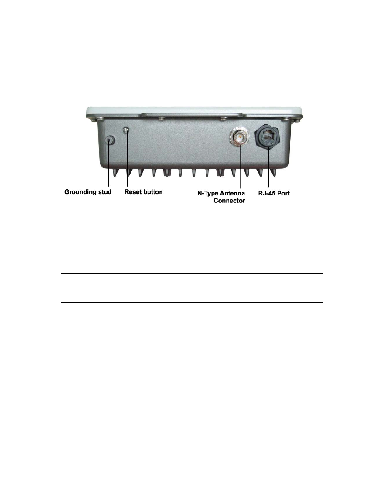
1-5 Hardware Description
Please refer to the following table for the meaning of each
feature.
ODU
1 RJ-45 Port
Use the SFTP CAT5 cable with weatherproof connector to connect to the “To ODU”
side of POE injector.
Figure 1-1 Halo Series Radio
2 N- Type Antenna
Connector
3 Grounding stud
4 Reset button
Here you can attach the proper an tenna with the Halo Series Radio to wirelessly connect
to other 802.11 a networks. In order to improve the RF signal radiation of y our ant enna,
proper antenna installation is ne cessa ry.
Connect to the ground conductor with the ground wire.
Remove the screw and use a th in obje ct (i.e. a paper clip, o r need le) to hold dow n the sw itch
inside for 5-10 seconds in order to reset the unit.
11
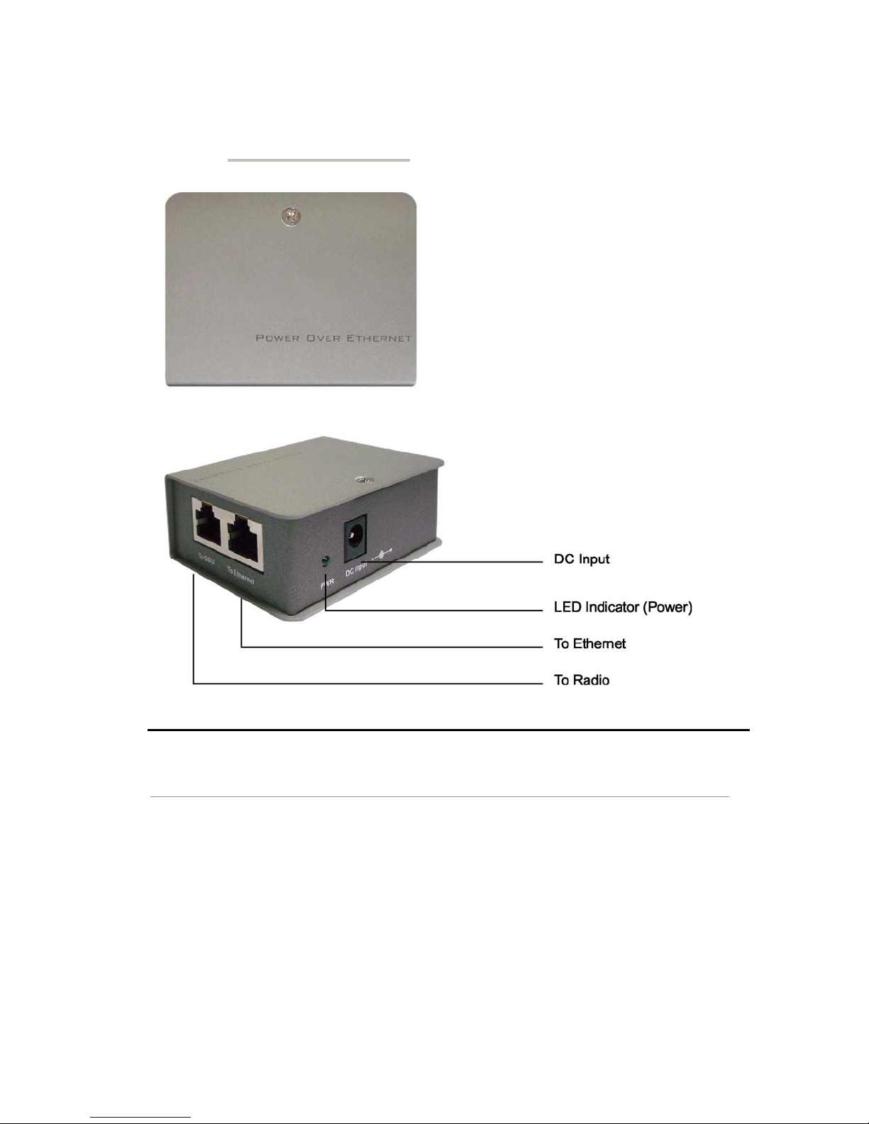
POE (Power over Ethernet) Injector
Figure 1-2 Power over Ethernet injector
1 To Ethernet RJ-45 port used to connect to the 10/100 Base T complied
device such as switch, router or PC.
12

y
y
y
This equipment must be grounded. Never defeat the ground conductor or
operate the equipment in the absence of a suitabl
conductor. Contact the appropriate electrical inspection authorit
electrician if you are uncertain that suitable grounding is available.
installed ground
or an
The Halo Series Radio and POE injector can be damaged by incorrect power
application. Read and carefull
connecing the system to its power source.
follow the installation instructions before
The Power Over Ethernet Injector is not a waterproof unit, should not be
exposed to outdoor without any protection.
13

1-6 Hardware Installation
The Halo Series Radio is a radio device, so it is susceptible to common causes of
interference that can reduce throughput and range. Follow these basic guidelines to
ensure the best possible performance:
IF IFthere is any other 5.2-5.8 GHz RF device deployed around the outdoor radio, try to
set the channel to a non-overlapping one.
InstallInst the bridge at a height sufficient place where structures, trees, or hills do not
obstruct radio signals to and from the unit. A cle ar line-of-sight path can guarantee the
performance of the RF link.
Site Surveys
Clear and flat areas provide better RF range and data rate, on the contrary, physical
obstructions such as trees, electric tower, hills or buildings can reduce the
performance of RF devices. Do not deploy your radios in a location where there are
any obstacles between antennas.
Configure and verify the 802.11a Halo Series Radio operations first before
you mount the radio in a remote location.
14
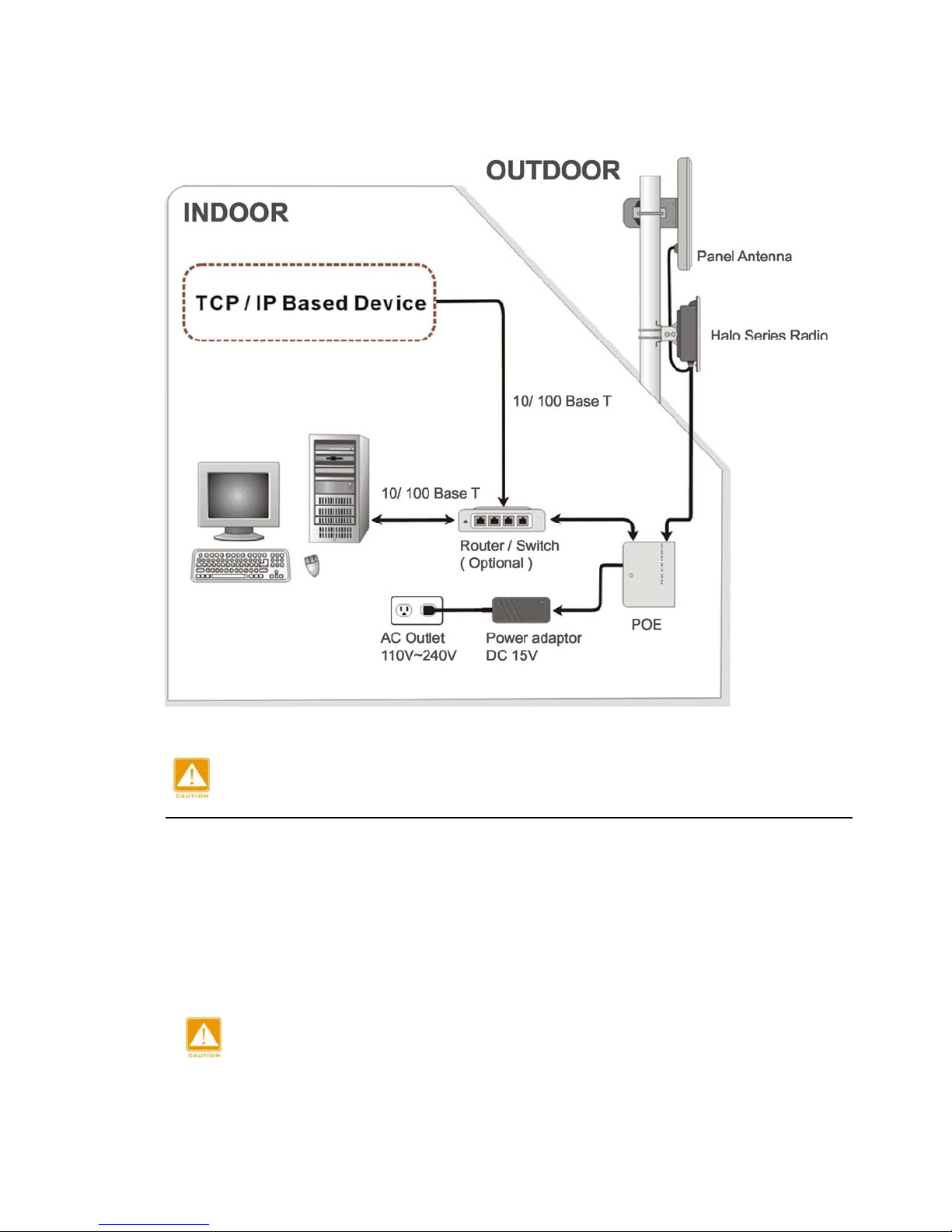
Figure 1-3 Hardware Installation Figure
Power Over Ethernet Injector is not a waterproof unit and it should not be
Connect the Ethernet Cable
exposed to the outdoors.
The Halo Series Radio support s 10/100M Ethernet connections. Attach your SFTP/
SSTP cat.5 Ethernet cable with waterproof connector to the RJ-45 connector on the
ODU enclosure. Then connect the other end of the cable to the “To ODU” side on
POE injector.
Solder the shielding parts of the SFTP cable and the RJ-45 connector well to
ensure optimal performance of the system.
15
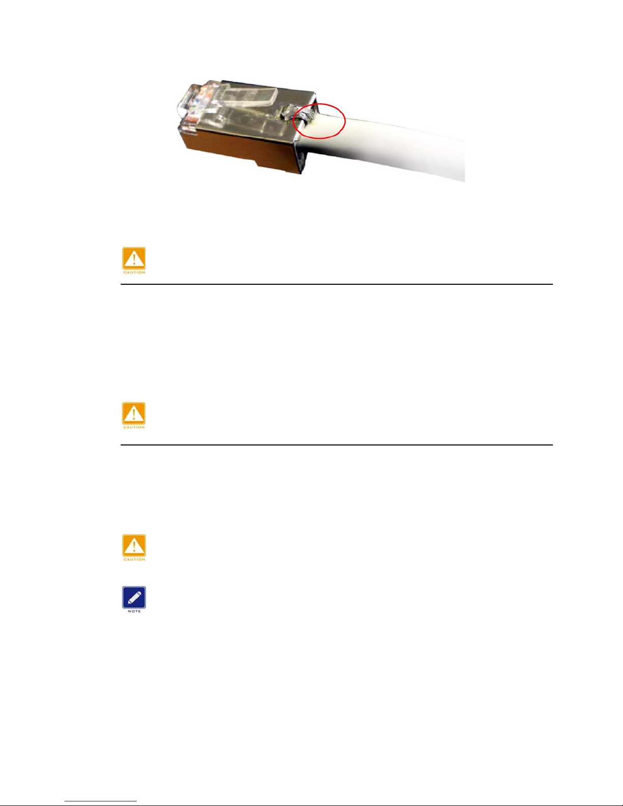
Figure 1-4 Weld the RJ-45 connector with the SFTP cable
Solder the SFTP cable as shown in Figure 2-4. The solder contact requires
that it is small in size so that it may fit into the connector properly.
Attached the antenna
You can attach the proper antenna to the N-type connector on the Halo Series Radio.
Ensure that all connections are sealed with an appropriate “tar type” sealant. Every
Halo includes two packages of Coax-Seal.
To meet regulatory restrictions, the outdoor radio and the external antenna
must be professionally installed.
Connect the Power Cable
Connect the 15V power adapter to the POE injector, and plug the other end to an
electrical outlet (AC 110V~240V).
Wireless Interactive cannot assume responsibility for damage when using the
Halo Series Radio with other types of power adapters.
You should read and carefully follow the installation instructions before
connecting the system to its power source. The outdoor radio and power
injector can be damaged by incorrect power application.
connections must
All
be properly connected before providing power to the radio.
16

Connect the grounding stud
y
y
Connect the grounding stud on the ODU enclosure with the ground wire.
This equipment must be grounded. Never defeat the ground conductor or
operate the equipment in the absence of a suitabl
installed ground
conductor. Contact the appropriate electrical inspection authorit
Mounting the 802.11a Halo Series Radio
electrician if you are uncertain that suitable grounding is available.
The outdoor radio is usually installed on a rooftop, tower, wall, or a suitable flat
surface. For detailed mounting instructions, please refer to the Quick Installation
Guide.
Only trained and qualified personnel should be allowed to install, replace, or
service this equipment.
Properly applying the Coax-Seal adhesive tape around the RJ-45 and N-type
connector on the outdoor radio enclosure is the last step of the mounting
process.
or an
Chapter 2. Antenna and RF Tutorial
Selecting Antenna Type
There are a vast number of antenna types designed for various general and special
purposes, but despite the huge variety, all designs essentially address two concerns,
directionality and gain. These selection criteria are discussed in the following
paragraphs, along with a third criterion, polarization.
Directionality
An antenna may be designed to receive and transmit in all directions. Such antennas
are omni-directional. An example of an omni-directional receiving antenna would be a
television antenna in a metropolitan area where each television station transmits its
signal from a different location relative to the receiver. Similarly, a centrally located
television transmitter would use an omni-directional transmitting antenna.
The sensitivity and power of an omni-directional antenna are unfocused; that is, they
are spread through a wide volume of space, so the advantage of being able to
communicate in all directions is traded off for limited sensitivity and power.
If it is determined that all signals of interest are coming from a definable direction, the
omni-directional antenna can be replaced by a directional or sectoral antenna, which
increases sensitivity and power by focusing the beam in the desired direction.
17

In practice, even omni-directional antennas take advantage of directionality by
r
focusing their sensitivity and power in the horizontal plane. Rather than waste
performance by sending signals into space or into the ground, the horizontal
omni-directional antenna redirects its power and sensitivity from these directions,
increasing performance in the horizontal plane.
In point-to-point applications, where the direction of communication is known and
fixed, a highly focused directional antenna can be used to provide maximum
sensitivity and power. In addition, because of its decreased sensitivity in all directions
but the desired one, the directional antenna improves performance by rejecting
signals not coming from the desired direction. This provides an effective increase in
signal-to-noise performance.
A sector antenna has a wider “spread” than a directional (generally between 60 to 120
degrees) which makes it a cross between an onmidirectional and a directional. This is
useful in a point to multipoint configuration where multiple sites are grouped in the
same general area. The installer can then make use of the higher sensitivity and
power but also take advantage of the wider beam pattern and improved front to back
ratio.
Gain
“Gain” specifies the receive and transmit performance of any antenna compared to a
standard omni-directional antenna (“spherical radiator”). The objective of a directional
antenna design is to achieve gain, improving sensitivity and effective radiating power to
increase range or data rate.
Gain is measured and stated in decibels, abbreviated dB. The decibel is a unit used to
indicate the relative difference in power between two signals. For example, a signal 3
dB greater than another signal has twice as much power. The decibel is a logarithmic
unit so each doubling of decibels represents a fourfold increase in power. Since 3 dB
represents a doubling of power, 6 dB represents a fourfold power increase, 12 dB
represents a 16-fold increase, etc. For antenna performance, the unit used is dBi, “i”
standing for “isotropic,” which describes the standard spherical radiation pattern.
One type of directional antenna available from Wireless Interactive is called a “semi
parabolic”. This antenna has a gain of 24 dBi, representing power and sensitivity
levels 256 times greater than those of a standard omni-directional antenna.
Polarization
Another important concept for antenna performance is polarization. An antenna
radiates radio waves that vibrate in a specific plane, normally horizontal or vertical.
Polarization refers to the restriction of wave vibration to a single plane.
Do not confuse polarization with directionality. The plane of wave vibration
has nothing to do with the direction of wave propagation. For example, an
antenna that focuses its energy in the horizontal plane may be vertically o
horizontally polarized.
Designs such as the semi parabolic offer a choice of polarization. Mounting a semi
parabolic antenna with the elements horizontal provides horizontal polarization, while
mounting the antenna with the elements vertical provides vertical polarization.
Similarly, the orientation of the radiating element of the parabolic antenna determines
polarization.
18

In setting up the Wireless Interactive system, either vertical or horizontal polarization
can be used, as long as polarization is the same at both ends of each link. For any
given pair of line-of-sight antennas, it is essent ial that they both have the same
polarization. Differences in polarization among antennas – called “cross-polarization” –
can reduce signal considerably.
Site Selection
At the high operating frequencies of a Wireless Interactive system, radio waves travel
in a nearly straight line-of-sight path. This is in contrast to the lower-frequency radio
waves used for AM broadcasting. These waves bounce between the ionosphere and
the earth’s surface to travel long distances and operate over and around obstructions.
Higher-frequency radio waves do not behave in this manner and are greatly
weakened by substantial obstructions or the absence of a direct path. Simply put, all
antennas communicating with each other in the radio network must be able to
physically “see” each other.
For this reason, a proper antenna site must meet the following criteria:
1. For optimum performance at maximum range, there must be a clear line-of-sight
path among all antennas that communicate directly with each other. At shorter
ranges, some degree of obstruction may be tolerated, but performance in the
presence of obstruction is difficult to predict.
2. Elevating one or more of the antennas in the system increases maximum line-ofsight range, called the radio horizon. If antennas are located at a greater range
than the ground-level radio horizon, a means must be available for elevating the
antennas.
3. All antennas must be properly oriented, and a directional antenna must be carefully
aimed at its target antenna to ensure communication at maximum range.
4. All antenna RF cables attenuate (reduce) signal strength in proportion to their
length. Therefore, the distance between the antenna and the radio is limited to a
cable length that does not exceed the maximum attenuation tolerated by the
system. Since various cable types offer different attenuation levels, maximum
length depends on cable type. Generally speaking, because most Wireless
Interactive systems are outdoor units with the output port connected directly to the
antenna, cable losses are negligible and the radio will compensate, but there are
limits to this compensation. See table 4-2 for sample cables and their respective
attenuation values.
Line-of-Sight Path
Because high-frequency radio waves are attenuated by obstructions, a clear
line-of-sight path between antennas is required for optimum performance at maximum
range. For shorter ranges, a degree of obstruction may be acceptable. For example,
at less than maximum ranges the radio has some ability to “penetrate” trees and other
foliage. On the other hand, geographical features (hills) and large buildings are likely
to interfere with communications, and antennas must be elevated to “see” each other
above such objects.
Because of the uncertainties of radio communication, it is difficult to predict the results in
conditions where obstructions exist. The only valid advice is to try the proposed
19

configuration and be prepared to move or elevate the antennas.
Radio Horizon (Maximum Line-of-Sight Range)
In visual terms, the horizon is the point in the distance where an object drops out of
sight because it is blocked by the earth’s curvature. If the observer or object is
elevated, the visual horizon is extended, that is, the object can be seen at a greater
distance before it drops out of view.
The same concept applies to radio signals: The radio horizon is the p oint in the
distance where the path between two antennas is blocked by the curvature of the
earth. Like the visual horizon, the radio horizon can be extended by elevating the
transmitting antenna, receiving antenna, or both to extend communication range.
The radio horizon can also be extended or shortened by certain phenomena such as
refraction due to atmospheric density and temperature inversions. Fog and rain,
which reduce signal strength, can also shorten the radio horizon although in the ISM
band, this loss is negligible.
A reasonable approximation of the radio horizon based on antenna height can be
obtained from the graph below. (Note that this graph does not take atmospheric effects
into account.) To use the graph, set a straight edge so that it crosses the height of one
of the antennas in the column on the left and the height of the other antenna in the
column on the right. The radio horizon in miles/km is shown where the straight edge
crosses the center column.
20
 Loading...