

GDI FDM-FSK User Manual

FDM-FSK
Fiber Optic Modem
With
Built in Model 4xx Series
FSK Modem
USER GUIDE
FDM Series
All Fiber Topologies - Compliant
(TI) 16 August 2006
GDI COMMUNICATIONS LLC
16 Aug 06 FDM-FSK Preliminary User Guide Dwg: A01230
PO Box 1330
280 I-80 Exit 1
Verdi, NV 89439
Phone: (775) 345-8000
Fax: (775) 345-8010
Email: support@sgdi.com
FDM Series of Fiber Optic Modems
Stand Alone Models Plug-in Models for Controllers and Racks
FDM-FSK
FDM-FSK
Data Ports
TXD
KOD RTS
RXD
Anti-Strm
Reset
LOS
R1
AB
T2
2/4 Wire FSK
CD
RTS
TXD RXD
DC Power Center
Main
Alarm Charging
GDI Communications
• Multiple Fiber Topologies in One Modem
• Combination Fiber Optic and FSK Modems
• Intuitive Fiber Status Display
• Fiber Identification
• Generates DTE Handshaking
• Auxiliary Data Port
• Built-in Uninterruptible Power Supply
LOS
KOD
CTS
Battery
T1
R2
FDM2SA
FDM-FiberHub
FDM-FiberHub
Link Activity
AB CD
TXD
TXD
RXD
RXD
Data Port Anti- Streaming
Alarm Reset
T1 R2
C
LOS
LOS
R1
AB
T2
LOS
DC Power Center
Main
Alarm Charging
GDI Communications
D
R1 T2
LOS
Battery
T1
R2
FDM170
MODEL FDM170
GDI Communications LLC
Verdi NV 89439
775-345-8000
RJ45
1 RI
1 8
2 CD
3 DTR
4 SG
TXD
RXD
LOS
R1
T2
DC Power Center
Main
Alarm Charging
GDI Communications
FDM2SA
Data Ports
KOD RTS
Anti-Strm
Reset
LOS
Battery
T1
R2
Single Ring, Dual Redundant Rings, Daisy Chain and Point to Point.
Built in FSK Modems for 2/4 wire Copper and Fiber Applications.
Pictorially indicates the switching status of the modem.
Display shows a 1 or 2 to indicate which port the fiber belongs.
Necessary for Remote Fiber to 2/4Wire FSK to TMC applications.
For 2/4Wire FSK or SS Radio Branch Circuits.
Provides Optical Continuity at a Failed Intersection.
FDM2070
FIBER STATUS
PWR
FAIL
ENABLE
T
U
T1
O
M
E
D
O
M
2
N
I
T
1
R
RXD 5
AUX
TXD 6
CTS 7
PORT
RTS 8
AUX CONN
BATTERY
DISABLE
2
R
FDM
2070-6D
MAIN DATA
TXD RXD
AUX DATA
TXD RXD
SERIAL
PORT
TXD RXD
RING STATUS
LOS
R1
PWR
RING 1
R1
T2
RING 2
GDI
NEVADA
ANTI-
STREAM
ALARM
RESET
T1
Fail
R2T2
LOS
T1
R2
16 Aug 06 FDM-FSK Preliminary User Guide Dwg: A01230

FDM -FSK ----- Table of Contents------ Page 1/3
FDM Series Overview 4
The FDM Series 4
FDM170 5
FDM2070 5
FDM-FiberHub 6
FDM2SA 6
Introduction to the FDM-FSK Modem 7
FDM-FSK
Basic Signal Flow Diagram 7
FSK Modem Section 7
Modem Ergonomics 8
Front Panel
Fiber Optic Modem Display s 9
2/4 Wire LED Displays 11
DC Power Center Display 11
8
Data Port Activity Display 9
TXD LED 9
RXD LED 9
Data Port Anti- Streaming 9
Reset Switch 9
Intuitive Fiber Status Displays 9
Fiber Identification 9
Fiber Status Displays for Redundant Rings and Daisy Chains 10
Fiber Status Displays for Single Rings 10
CD Carrier Detect 11
KOD Key On Data 11
RTS Request To Send 11
CTS Clear To Send 11
TXD Transmit Data 11
RXD Receive Data 11
DC Power Center LED Indicators 12
Main 12
Charging 12
Battery 12
Alarm 12
16 August 06 FDM-FSK Preliminary User Guide 1 Dwg: A01230

Rear Panel 12
Power Connections 12
Dual Data Ports 13
Optical Ports 13
Bottom Panel 13
Signal Flow Diagrams 14
Sequence of Events 14
Data Port Flow Diagrams 15
Setting up the Modem 16
Mounting Options 16
Configuring the FDM Modem Section 16
FDM DIP Switches 17
Master/Salve 17
Topology Selections 17
2 Rings (Self Healing Dual Counter Rotating Rings). 17
1 Ring 17
Daisy Chain 17
Data Protocol
RS232/422 18
Baud Rates 18
Parity 18
RTS/CTS Handshaking 18
CTS Delay 18
Anti-Streaming 19
Optical Dynamic Range 19
Fiber Identification Techniques 20
Fiber Applications
Self Healing Dual Counter Rotating Ring Operation 21
Single Ring Operation 23
Point to Point 25
Point to Point with Redundant Fiber Path 26
Daisy Chain Operation 28
Dual Daisy Chain (Center Master) 30
21
16 August 06 FDM-FSK Preliminary User Guide 2 Dwg: A01230

Configuring the FSK Modem Section 31
Primer on Frequency Shift Keying Modems 31
Communications Sequence of Events 32
The Pole 32
The Response 33
Front, Rear and Bottom Panels 34
2/4 Wire FSK Display
CD 34
RTS 34
CTS 34
TXD 34
RXD 34
KOD 34
Rear Panel 34
Copper FSK 34
Bottom Panel DIP Switches 35
Full Duplex or Half Duplex 35
RTS to CTS Time 35
Carrier Turn Off Time 35
Local Echo 35
Receiver Squelch Time 35
Carrier Detect Time 35
Load Compensation 35
FSK Applications 36
Half Duplex Operation (2 Wire “One Pair”) 36
Full Duplex Operation (4 Wire “2 Pairs”) 37
A Word on Dynamic Range 38
Combined FDM and FSK Applications 39
Fiber to Copper to Fiber --- Copper Bridge Application 40
Copper to Fiber to Copper --- Fiber Bridge Application 40
Fiber with Copper Branch --- Copper Tap Application 41
Factory Default Settings and Pin-Out Diagrams 42
KOD Jumper 43
Care and Handling Procedures for Optical Connectors 44
Disclaimer 47
16 August 06 FDM-FSK Preliminary User Guide 3 Dwg: A01230

FDM SERIES OVERVIEW
The FDM Series of Hardened Modems are designed for polling applications utilizing
RS232/422 Asynchronous transmission over Multimode and Singlemode Fiber
Optics. All modems in the series are communications compatible with each other,
thus allowing greater flexibility of use.
The FDM Series comprise of six Digital Modems:
1. The FDM2SA is a Stand Alone version.
2. The FDM170 is a Plug-in version for the 170 Controller
3. The FDM2070 is a Plug-in version for the 2070 Controller
4. The FDM FiberHub performs as a 1 x 3 star optical hub that ties in
optical branch circuits into the mainstream communications path.
5. The FDM-FSK is a combination of a FDM2SA and a FSK modem.
6. The FDM-SSR is a combination of a FDM2SA and a Spread Spectrum
Radio.
The modems can operate in many different topologies, even on a simple fiber ring
when there is only one fiber available, later as more fibers become available,
simply flip a switch to change to the new topology.
This unique capability of operating in multiple topologies offers the advantage of
One Modem for all Topologies.
Switch Selectable Topologies are as follows:
• Single Fiber Ring
• Dual Fiber Redundant Ring (Self Healing)
• Point to Point
• Daisy Chain Format.
The modems have a high dynamic range yet they are immune to optical over
loads, therefore no optical attenuators are required for short runs or even bench
top “back to back” testing!
Any modem can be designated as a Master or Slave, also for Auto Restoration
any modem can be designated as an Auxiliary Master.
16 August 06 FDM-FSK Preliminary User Guide 4 Dwg: A01230

FDM SERIES OVERVIEW continued
A unique and intuitive Dual Seven Segment display graphically indicates the
status of the fiber system, making diagnostics visually simple. All FDM series
modems have the unique capability of Fiber Identification; the display will flash a
1 or 2 indicating which circuit the fiber belongs to.
Other advantages include multiple use Dual Data Ports enabling branch circuit
capabilities such as an On Street Master to Local Controller (same location), or
4wire or Spread Spectrum Radio communications.
All modems have the unique capability of having their Auxiliary Port switched
from DCE to DTE mode. This feature allows the Main port to drive the Aux-Port
as well as the fiber, primarily used for Street Master communications with the
local controller or driving some other modem.
Only FDM optical modems have the unique ability to generate a Carrier Detect
both before and after data flow, this is essential when connecting to 2 Wire FSK
communications. This Dynamic CD acts like a “DTE’s RTS” and is used to
initiate handshaking to a DCE’s RTS input.
The FDM Series represents a new generation of digital fiber optic modems
utilizing a Replaceable Operating System (ROS). As requirements change, or new
features become available, a new program can be loaded so as to provide a
migration path to upgrade the existing system.
FDM170
This is a Plug-In version for the 170 Series of Controllers and the R400/R800
Rack Series. The Main Data port is connected via the card edge connector to the
170 backplane while the Aux Data Port RJ45 is front accessible for combining
external data links in the polling stream.
For rack-mounted communications at the Traffic Maintenance Center, R400/R800
Series Racks can be populated with the FDM170 to complete the communications
system.
FDM2070
This is a Plug-In version for the 2070 Series of Controllers. The Main and
Auxiliary Data ports provide the same functionality as in the FDM170, plus one
of the 2070’s spare Serial Ports SP2 or SP4 (slot dependant) is also brought out to
the front panel. For rack-mounted communications at the Traffic Maintenance
Center, R400/R800 Series Racks would be populated with the FDM170 to
complete the communications system.
16 August 06 FDM-FSK Preliminary User Guide 5 Dwg: A01230

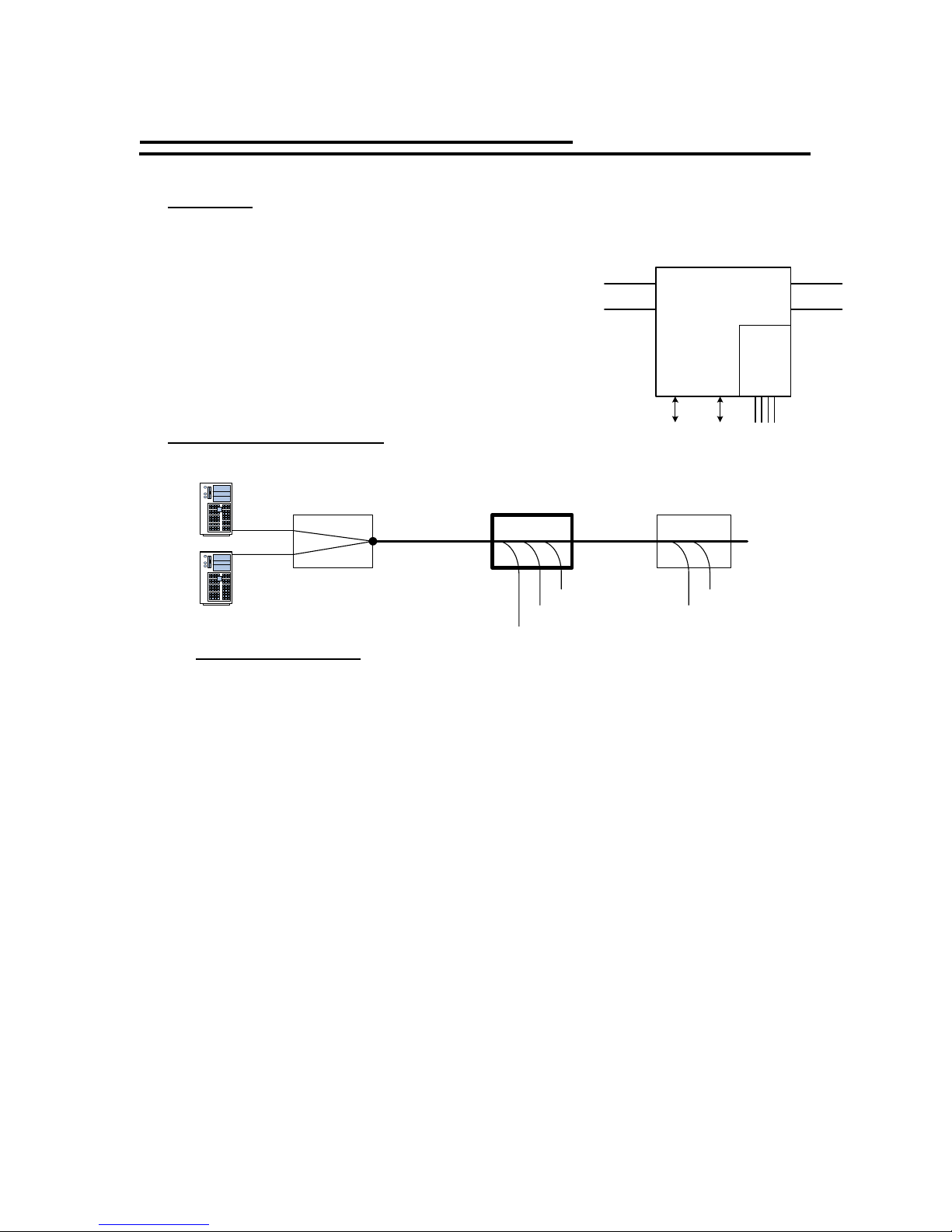
FDM FiberHub
N
The FiberHub is designed to act like a hub or star that ties
four optical branch circuits together in a 1 x 3
A typically deployment would be anywhere in a fiber
arterial daisy-chain or ring at an intersection where it ties
WE
in the “North/South” cross street optical branch circuits
into the “West/East” main arterial fiber run. As with all
FDM modems , data ports are provided for the local
controller and auxiliary communications.
S
FDM2SA
This is the “Stand Alone” version and has two Data Ports, one designated as the
Main Port, the other being an Auxiliary Port. The Main Data Port is used for
connection to a controller. The Auxiliary Data Port can be used for many
associated functions such as connecting to a Backup Server or for Over the Air
Restoration, or combining external data links into the polling stream.
A unique built-in Key on Data capability allows the fiber modem to act as DTE
and provide all necessary handshaking. This unique feature allows a Remote Fiber
System (Tail Circuit) to be integrated into a 4wire FSK circuit and on to city hall.
FDM-FSK
This user guide describes the FDM-FSK and its operation.
16 August 06 FDM-FSK Preliminary User Guide 6 Dwg: A01230
INTRODUCTION to the FDM-FSK
FDM-FSK
The FDM-FSK is a combination of the FDM2SA
Fiber Optic Modem and GDI’s Model 4xx Series
FSK Modem, basically it is two interconnected
modems housed in the same enclosure. Two RS232
Data Ports are provided along with the 2/4 Wire
FSK Port, all three ports communicate to and from
the fiber to the originating “master source”, see
diagram below.
Basic Signal Flow Diagram
Fiber Trunk
FDM-FSK Modem
R1
FDM2SA
Fiber Optic
Modem
T2
FSK
Modem
Aux-
Port
2/4Wire
Port
Main
Port
RS232 RS232 2/4 Wire
T1
R2
Fiber Trunk
Main Server
Back-up Server
TMC or Street Master
Main Port
Aux-Port
Series
Master
FDM
Fiber Optics
Remote Controller
Location
FDM-FSK
Main Port
Aux-Port
Remote Controller
Location
FDM
Series
Aux-Port
Main Port
FDM2SA
FDM170
FDM2070
FDM-SSR
FDM-FiberHub
FSK 2 or 4 Wire
FSK Modem Section
The FSK Modem is based on the industry standard Model 4xx series of modems
which are designed for asynchronous RS232 communications over un-terminated
private wire utilizing Frequency Shift Keying techniques (tones). The modems
data port is tied into the fiber optic data stream to provide bi-directional
communications between Fiber and FSK. The FSK Modem can communicate in 2
Wire Half Duplex or 4 Wire Full Duplex at baud rates up to 19.2Kbt/s depending
on which FSK Modem is installed. The FSK modem is 100% compatible with all
GDI modems.
The FSK section allows a number of options:
• Connecting a remote copper 2/4 wire circuit into the fiber system and
back to City Hall.
• Connecting a remote fiber system into the 2/4 wire system and back to
City Hall.
• Connecting Copper to Fiber to Copper. (Fiber Bridge)
• Connecting Fiber to Copper to Fiber. (Copper Bridge)
16 August 06 FDM-FSK Preliminary User Guide 7 Dwg: A01230

Modem Ergonomics
The Front Panel displays information on the status of the FDM-FSK.
The Rear Panel is where all the connections are made to the modem and the
switch-able options are located on the Bottom Panel to minimize ingress of
foreign material in road side cabinet applications.
On the Rear Panel, there are two dual bulkhead Fiber Ports which can be easily
changed between ST, FC and SC style connectors; so can the internal mini
patchcords located between the bulkheads and the optical transceivers.
These inexpensive patchcords act like a “fusible link” and provide the
transceivers with 100% protection from being damaged by external dirty
patchcords. Replacing the patchcords can be easily done by the customer.
Two Data Ports, Main and Auxiliary are provided, the Main Data Port DB9
typically connects to the local controller while the Auxiliary RJ45 connector can
be used to bring in radio based communications into the main data stream.
The FSK Port can operate in 2 or 4 wire mode (Half/ Full Duplex) and is 100%
compatible with all GDI FSK Modems
The FDM-FSK has three mounting options, left or right wall mounting via a pair
of “Keyhole” slots on both sides, or as a Stand Alone shelf mounted unit while
still maintaining a vertical front panel view for all three options.
The FDM-FSK has an optional internal Uninterrupted Power Supply “UPS” that
maintains full modem operation without any loss of communications.
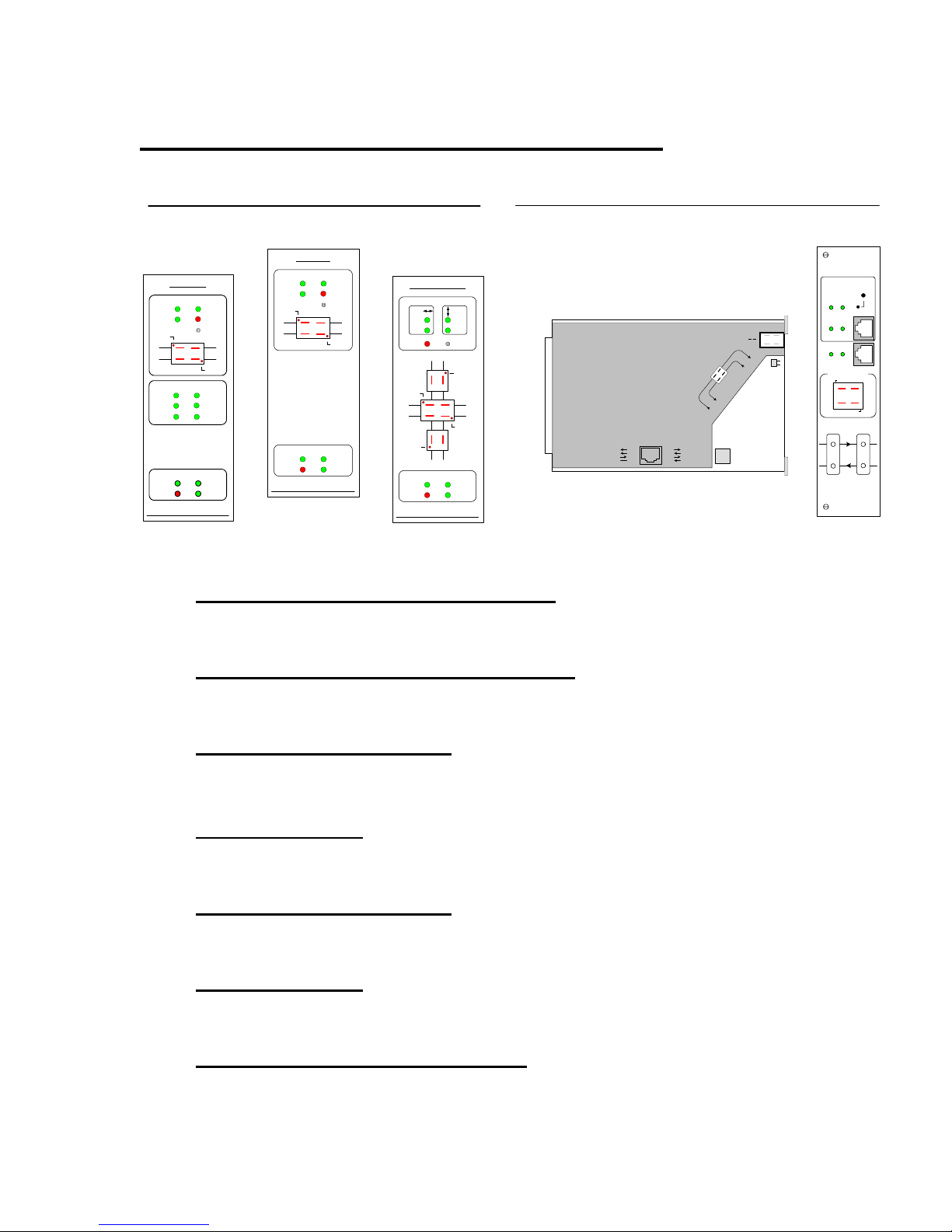
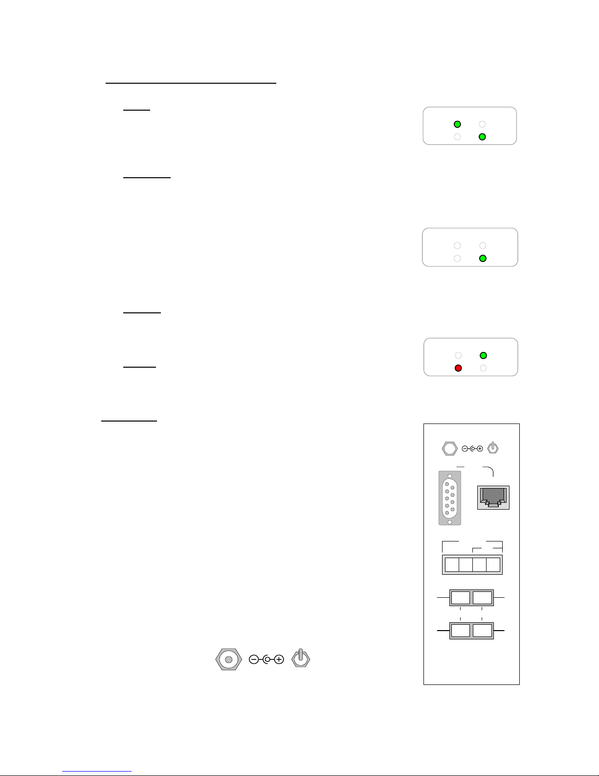
Front Panel Displays
The FDM-FSK front panel has three distinctive information
displays:
• The upper display is for the Fiber Optic Modem.
• The middle display is for 2/4 wire FSK Modem.
• The lower display is dedicated to the DC Power Center
FDM-FSK
Data Ports
TXD
RXD
LOS
R1
T2
CD
RTS
TXD RXD
DC Power Center
Main
Alarm Charging
GDI Communications
2/4 Wire FSK
KOD RTS
Anti-Strm
Reset
BA
LOS
KOD
CTS
Battery
T1
R2
16 August 06 FDM-FSK Preliminary User Guide 8 Dwg: A01230
Fiber Optic Modem Displays
Data Ports Activity Display
This section displays the activity of data through the modem.
TXD LED
This indicates data activity from the fiber to the data port.
RXD LED
This indicates data activity from the data port to the fiber.
KOD
This indicates Data from the fiber is asserting (Keying) the
FSK Modem’s RTS and the Auxiliary Port’s DCD.
Data Port Anti-Streaming Alarm LED
This indicates port data exceeded selected time out.
Reset Switch
Switch for resetting Anti-Streaming Alarm.
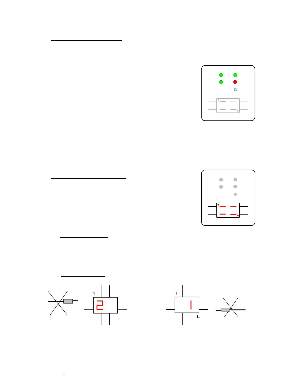
Intuitive Fiber Status Displays
The seven segment displays show information as to the
integrity of the fiber system, each of the red segment lines
represent the incoming or outgoing fiber data path through
the modem, while LOS indicates a loss of incoming optical
signal.
Fiber Identification
Identifying whether a fiber has Receiver 1 or Receiver 2 traffic is as simple as
plugging in and out each fiber into any receiver, the modem will flash the
message 1or 2 to denote which receiver that fiber belongs to.
See Installation Section
-- Fiber Identification Techniques, page 22 for more details.
LOS
R1
R2
AB
T2
LOS
T1
R2
Data Ports
TXD
RXD
LOS
R1
AB
T2
Data Ports
TXD
RXD
LOS
R1
AB
T2
LOS
R1
T1
AB
T2
R2
LOS
R1
KOD RTS
Anti-Strm
Reset
T1
R2
LOS
KOD RTS
Anti-Strm
Reset
T1
R2
LOS
Display indicates patchcord belongs in R2.
16 August 06 FDM-FSK Preliminary User Guide 9 Dwg: A01230
Display indicates patchcord belongs in R1.
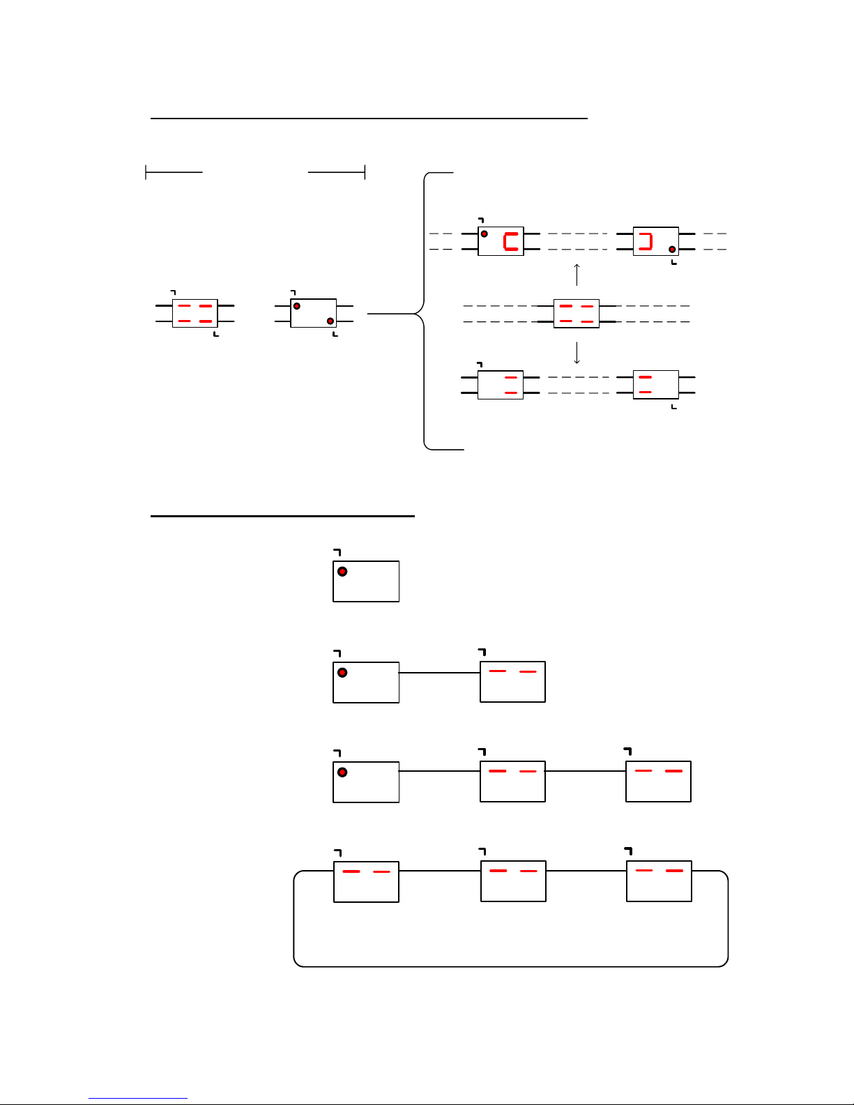
Fiber Status Displays for Redundant Rings and Daisy Chains
Common Displays
Normal Display.
(Displays not Flashing)
LOS
R1
T2
Flashing Display indicates a
Transport Layer fault on the
Fiber System.
All Modems Flash
LOS
T1
R2
Loss Of Signal
LOS LED’s Flashing
LOS
R1
T2
LOS
T1
R2
Fiber Status Display for Single Rings
LOS
Loss of signal on R1
Master
LOS
Displays will Flash
Master
LOS
Displays will Flash
Master
LOS
Master
Redundant Ring Displays
Daisy Chain Displays
T1R1
T1R1
T1R1
T1R1
Loss of Signal Causes Local LOS and Fold Back to
LOS
R1
T2
LOSS of R1 causes
No LOS by default on first
R1
No Fiber
T2
First Modem set
to Daisy Chain
LOS
Flash (Ring Alarm Condition).
T1
R2
R2/T2 Foldback
R1
T2
modem
T1
R2
T1R1
R1
T2
LOSS of R2 causes
T1
R2
No LOS by default on last
R1
T2
Slave 1
LOS
T1R1
LOS
Slave 1 Slave 2
LOS
T1R1
LOS
Slave 1 Slave 2
LOS
R1/T2 Foldback
modem
LOS
Last Modem set
to Daisy Chain
T1
R2
T1
No Fiber
R2
T1R1
T1R1
16 August 06 FDM-FSK Preliminary User Guide 10 Dwg: A01230

2/4 Wire FSK Display
This section displays the activity of data through the FSK Modem.
CD LED
This indicates the modem has detected a carrier tone from a
remote modem on the 2/4 Wire circuit.
KOD
This indicates Data from the fiber is asserting (Keying) the FSK Modem’s RTS.
RTS LED
This indicates the Fiber Optic modem has asserted RTS to the FSK modem.
CTS LED
This indicates the FSK modem has asserted CTS to the Fiber Optic Modem.
TXD LED
This indicates data is being transmitted from the Fiber Optic modem to the FSK
Modem.
RXD LED
This indicates data is being received from the FSK Modems 2/4 Wire circuits
DC Power Center Display
The DC Power Center shows the power state of the FiberHub.
The DC Power Center provides information on the status
of the optional internal Uninterrupted Power Supply
(UPS), such as incoming Main power, battery Charging
(full and trickle charge), Alarm (no external power) and
Battery power only.
If the modem is equipped with an optional internal UPS
and power fails, the supported modem(s) will be fully
operational until the batteries are depleted. Resumption of
power will start the battery charging process while at the
same time the modem will be fully operational.
If the installation site supports a 24VDC UPS this may be
connected to the DC power connector on the modem in
lieu of an internal UPS.
2/4 Wire FSK
CD
RTS
TXD RXD
DC Power Center
Main
Alarm Charging
Normal Condition
Running on Main Power and
charging the batteries
DC Power Center
Main
Alarm Charging
Incomi n g Power Fa ilure
Running on Battery Power with
an Alarm indication.
KOD
CTS
Battery
Battery
16 August 06 FDM-FSK Preliminary User Guide 11 Dwg: A01230
DC Power Center LED Indicators
Main
Indicates the modem is running of external power and is
paired with the Charging LED.
Charging
The LED has two indicating modes,
1. On Solid, this indicates the battery is being charged at the maximum
rate.
2. Pulsing indicates the battery has reached a full
charge state and is being maintained. Pulse duty
cycle varies with the state of charge.
Battery
Indicates the modem is running on batteries only and is paired with the Alarm
LED.
Alarm
Indicates external power has failed.
Rear Panel
The rear panel is where the Fiber Optic, Data, FSK
2/4Wire and Power connections interface to the modem,
note that the fiber connections logically match the front
panel fiber displays. The FSK connection diagram
illustrates how to correctly connect 2 or 4 wire copper
applications.
Power Connections
The modem can be connected to an external 24VDC UPS
via the DC Jack, also a battery disconnect switch is
provided for shipping or storage purposes.
18-30VDC
Battery
Enable
Disable
DC Power Center
Main
Alarm Charging
DC Power Center
Main
Alarm Charging
DC Power Center
Main
Alarm Charging
18-30VDC
Main
In Out
R1
A
T2
Battery
Battery
Battery
Battery
Enable
Disable
Ports
Aux
1 8
18
4W FSK
2W
B
T1
R2
16 August 06 FDM-FSK Preliminary User Guide 12 Dwg: A01230
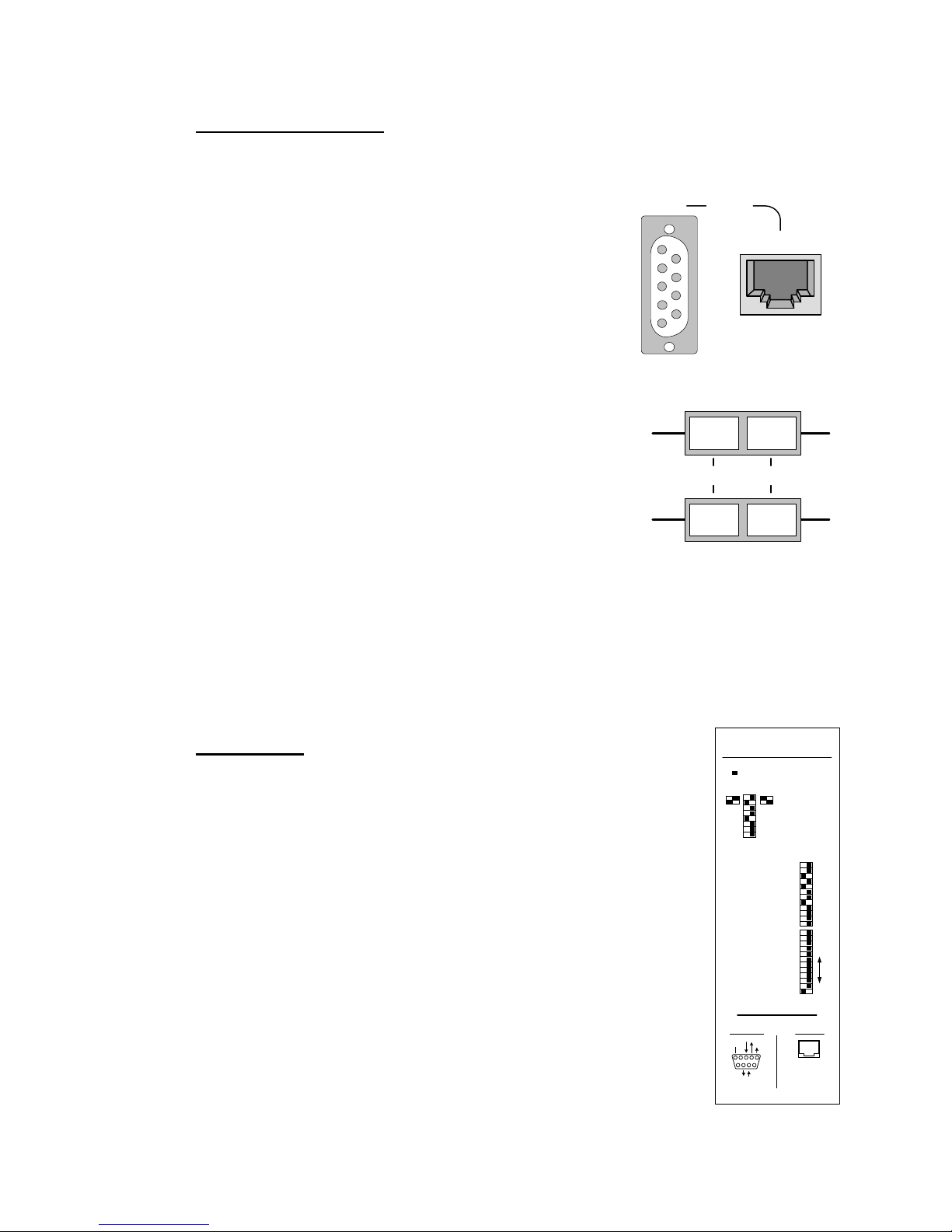
Dual Data Ports (FDM)
The fiber optic modem has Dual RS232 Data Ports (Main and Auxiliary).
This is a single channel with dual ports, the main
Data Port DB9 connector goes to the local
controller while the Auxiliary RJ45 connector can
Main
Ports
Aux
be used to bring in auxiliary or radio based
communications into the main data stream. The
1 8
Aux Data Port can be switched to operate as RS422
interface.
18
Optical Ports
The craft friendly layout of the optical ports
R1
T1
matches the Front Panel Fiber Display which
makes for ease of installation.
A B
The designation A & B refer to Port Designations
when connecting to the FDM-FiberHub.
T2
R2
The optical ports are dual hybrid adapters that are
easily interchangeable should a different style of connector be required such
as ST, FC and SC.
These hybrid adapters are coupled to the main optical transceivers through
replaceable mini patchcords that isolate and protect the main optics from
damage due to external dirty or damaged patchcords.
Bottom Panel
This panel is where the FDM-FSK is set up for Fiber and FSK
Operation. Data rates on both the FDM and FSK modems must
be the same for obvious reasons.
Pin out connection diagrams are also included on this panel to
assist the technician when making interconnect cables. The
FSK Connections are shown on the rear panel.
Switch settings are described on page 17 for the FDM and page
35 for the FSK.
Port Switch Assignment
Switch Actuator
Full
Half
Duplex
Duplex
6ms
5ms
On (Half)
3ms
4ms
600 Ohms
Aux. Master
Daisy Chain
19.2Kbts
38.4Kbts
57.6Kbts
115.2Kbts
RTS-CTS Off
CTS-0ms 8ms
Ant-Strm Off
Aux.Port DCE DTE
RXD
DCD
15
69
RTS to CTS Time
Cxr. Turnoff Time
Local Echo
Rcr. Squelch Time
Cxr. Detect
Load Compensation
Master
2 Rings
RS232
1200
2400
9600
Parity None
Odd Even
2
4
8
18
32
64 Off
Auxiliary
RS-232 RJ45
18
2 DCD
4 GND
5 RXD
NO CONNECTION
PINS 1-3
12ms
10ms
(Full) Off
6ms
8ms
Hi
Data Port Pinouts
Main
RS-232 Female
TXD
GND
CTS RTS
NO CONNECTION
PINS 4-6-9
Slave
Off
1 Ring
Ring
RS485
Off
Off
Off
Off
Off
Off
Off
6 TXD
7 CTS
8 RTS
16 August 06 FDM-FSK Preliminary User Guide 13 Dwg: A01230
 Loading...