


Model 4xxSA
Stand Alone
FSK Modem
USER GUIDE
(TI) 4 Jan 06
GDI COMMUNICATIONS LLC
PO Box 1330
280 I-80 Exit 1
Verdi, NV 89439
Phone: (775) 345-8000
Fax: (775) 345-8010
Email: support@sgdi.com

Contents
Modem Basics 3
Communication Sequence of Events……………………………………………...4
The Pole…………………………………………………………………………...4
The Response……………………………………………………………………...5
Introduction to the 4xxSA Series of Modems 6
Model 4xxSA Modems…...……………………………………………………….6
The KOD Option………...…………………...……………………………………6
Front, Rear and Bottom Panels…………………………………….…………..7
Front Panel………...………………..……………………………………………7
Front Panel LED’s……………………………………………………………....7
Rear Panel……………………..…………………………………………..……..8
Dual Data Ports…………………………………………………………………8
Copper FSK…………………………………………………………………….8
Power Connections……………………………………………………………..8
Bottom Panel……………………………….……………...…………...………...9
DIP Switches……………………………………………………………………9
Full or Half Duplex………………………….……………………………….9
RTS to CTS Time…………………………………………………………….9
Carrier Turn Off Time………………………………………………………..9
Local Echo……………………………………………………………………9
4xx Preliminary Generic User Guide. 4 Jan 06 1

Contents……continued
Receiver Squelch Time………………………………………………………9
Carrier Detect………………………………………………………………...9
Load Compensation…………………………………………………………10
KOD Function………………………………………………………………10
KOD Direction……………………………………………………………...10
KOD Delay………………………………………………………………….10
Anti-Streaming……………………………………………………………...10
Data Protocol………………..…………………………………………...……...10
RS232………………………………………………………………………….10
RS422………………………………………………………………………….10
Applications _________ ___11
Half Duplex Operation (2 Wire)……………….………………………………...11
Full Duplex Operation (4 Wire).………………………………………………...12
Modems with the KOD Option Installed………………………………………..13
Internal KOD…………………………………..……………………………13
External KOD……………………………………………………………….13
KOD Applications…………………………………………………………..14
More Applications………………………………………………..................15
Repeater Applications……………………………………………………………16
A Word on Dynamic Range……………………………………………………..17
Notes……………………………………………………………………………..18
4xx Preliminary Generic User Guide. 4 Jan 06 2
Modem Basics
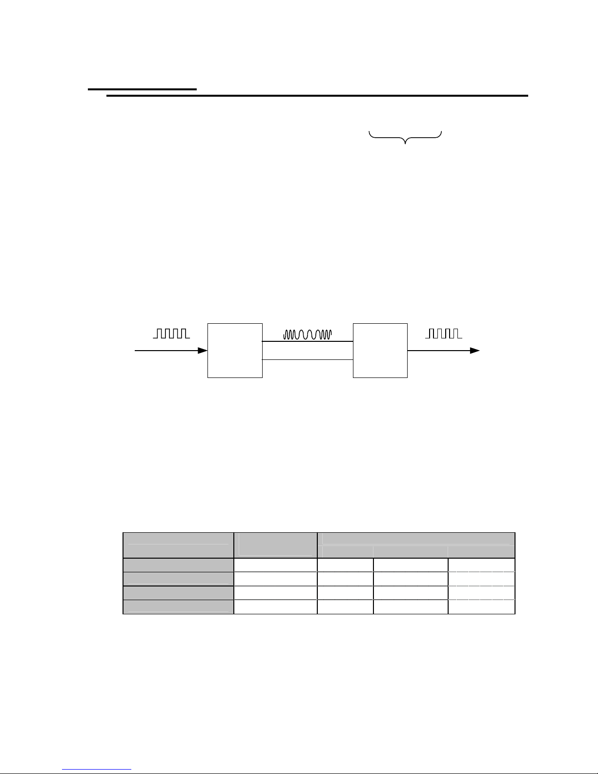
The term Modem is a combination of two words, Modulator and Demodulator.
Modem
Frequency Shift Keying (FSK) Modems are designed to convert digital data to
tone frequencies, this process is called modulation. The frequencies can easily be
transmitted via a communication line to the receiving modem. At the opposite end
of the communication line the tone frequencies are converted back to digital data
by a process known as demodulation. By using this mechanism, two digital
devices, such as Traffic Maintenance Center’s (TMC) Computer and a Remote
Controller can communicate with each other via the outside cable plant.
The 4xx series of modems use a modulation technique known as Frequency Shift
Keying (FSK). Digital information is binary in format: that is, data is represented
by either logic high or logic low (1 or 0). Communications terminology refers to
logic Low as Mark and logic High as a Space. FSK Modems utilize this fact and
generate a unique frequency for each logic level. Each model in the 4xx series
have their own unique set of frequencies due to the baud rate therefore only
modems of the same model number can communicate with each other, see the
following chart.
Baud Rate
Mark Frequency
Space Frequency
Soft Carrier
The rate at which the communication line changes state is known as the baud rate,
this can be interpreted to be equivalent of bits per second.
The 4xx Series of Modems are capable of communicating at baud rates up to
19200Kbts depending on the model.
Digital
Transmit Section of
Modem 1
Modulator DemodulatorTransmit Cable Pair
Input/Output
1200 9600 19200
Low (0) 1200Hz 11200Hz 19200Hz
High (1) 2200Hz 17600Hz 38400Hz
900Hz 7800Hz 13800Hz
Tones
Receive Section of
Modem 2
Digital
Model # RS232
400SA 496SA 419SA
4xx Preliminary Generic User Guide. 4 Jan 06 3
Communications Sequence of Events
For ease of understanding this sequence of events we will limit our discussions to
one modem at the TMC and one Remote modem connected to a Controller over a
4 wire system.
Note; Transmit and receive pairs are referenced to the “Master” end of a 4 wire
circuit, also a modem has a Transmit Section and a Receive Section.
The Pole
TMC
Computer
“Master”
RTS
CTS
DATA
Transmit
Section
Transmit Pair
Receive
Section
CD
DATA
Remote
Controller
1. The TMC computer (Master) signals the modem that it wants to transmit
data by raising Request To Send (RTS) at the modems input. The modem
returns a Clear To Send (CTS) back to the TMC computer after a time
delay (user selectable). This is called Handshaking.
As soon as the “master” modem sees RTS it transmits a Mark tone down
the copper wire to wake up the remote modem.
2. The Remote Modems Carrier Detect (CD) circuit sees the Mark tone. If
the tone is continuous for 4 or 8ms (user selectable) the Carrier Detect
circuit will validate it and unlock the receivers output (removes Receiver
Squelch) and raise CD at the data port. This CD signal advises the
Controller to expect data. The demodulated Mark tone, logic 0, is passed
to the RS232 Data port, where it does not change state due to the fact that
when not in use it is always at logic 0, same as the transmit end. Now let’s
go back to the TMC end.
3. Once the TMC computer receives CTS (clear to send) it will send data to
the modem. At this juncture both modems on the system are in a “go”
state.
4. The TMC computer now sends data (0’s and 1’s) to the modem which
converts it to Mark and Space frequencies. These frequencies (tones) are
then transmitted down one pair of wires known as the transmit pair to the
Remote modems receiver.
When the data ends, RTS is lowered and the modem transmits a short
burst of Soft Carrier (tone is out of band of the Mark/Space frequencies).
This lower frequency tone causes the receiving modem to squelch the
input to the digital circuits. This action “closes the modems door” to
prevent noisy lines from false triggering the data circuits. The modem is
now quiet.
5. We have now completed the Polling phase.
4xx Preliminary Generic User Guide. 4 Jan 06 4

The Response
TMC
Computer
CD
DATA
Receive
Section
Receive Pair
Transmit
Section
RTS
CTS
DATA
Remote
Controller
1. The Controller recognizes its address and prepares a message to be sent
back to the TMC computer. Our response message will be sent back to the
TMC on the Receive Pair of the 4wire system.
2. The Controller (Remote) signals the modem that it wants to send data by
raising Request To Send (RTS) at the modems input. The modem returns a
Clear To Send (CTS) back to the Controller after a time delay (user
selectable). This is called Handshaking.
As soon as the “remote” modem sees RTS it transmits a Mark Tone down
the copper wire to wake up the “Master” modem.
3. The TMC Modem’s Carrier Detect (CD) circuit sees the Mark tone. If the
tone is continuous for 4 or 8ms (user selectable) the Carrier Detect circuit
will validate it and unlock the receivers output (removes receiver squelch)
and raise CD at the data port. This CD signal advises the TMC computer
to expect data. The demodulated Mark tone, logic 0, is passed to the
RS232 Data port, where it does not change state due to the fact that when
not in use it is always at logic 0, same as the Controller end. Now let’s go
back to the Controller end.
4. Once the Controller receives CTS (clear to send) it will send data to the
modem. At this juncture both modems on the system are in a “go” state.
5. The Controller now sends data (0’s and 1’s) to the modem which converts
it to Mark and Space frequencies. These frequencies (tones) are then
transmitted down the receive pair of wires to the TMC modems receiver.
6. At the TMC modems receiver the Mark and Space frequencies are
demodulated into 0’s and 1’s respectively. This is the same bit pattern that
the Controller sent to the modem for transmission. This data is then sent to
the TMC computer via the communication port.
When the data ends, RTS is lowered and the modem transmits a short
burst of Soft Carrier (tone is out of band of the Mark/Space frequencies).
This lower frequency tone causes the receiving modem to squelch the
input to the digital circuits. This action “closes the modems door” to
prevent noisy lines from false triggering the data circuits. The modem is
now quiet.
7. We have now completed the Response phase.
4xx Preliminary Generic User Guide. 4 Jan 06 5

INTRODUCTION to the 4xxSA Series of Modem
Model 4xx Stand Alone Modem
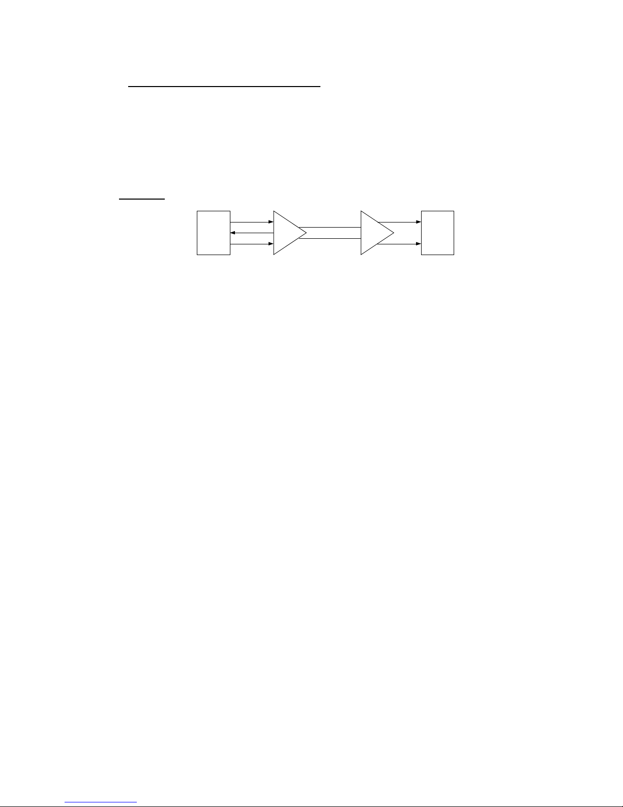
The 4xxSA Series is an asynchronous modem designed for RS232/422/485*
communications over un-terminated private wire utilizing Frequency Shift Keying
techniques (tones). The modems can communicate in 2 Wire Half Duplex or 4
Wire Full Duplex at baud rates up to 19.2Kbt/s depending on the model, all have
adjustable timing parameters. The modems are typically deployed in a Point to
Multi-point configuration such as TMC Master polling scheme that communicates
with Remote Traffic Controllers.
An ergonomic design has been employed that groups all the status information on
the front panel, all the switch selectable options on the bottom panel and all the
connections to and from the modem on the rear panel.
Two Data Ports are provided, Main and Auxiliary, the main Data Port DB9
typically connects to a TMC Master or a local controller while the Auxiliary RJ45
connector can be used to bring in Fiber or Radio based communications into the
main data stream. The modem has unique ability to generate RTS handshaking to
itself or to an attached device when the KOD option is installed.
*RS422/485 is an option that must be specified at the time of order.
The Key On Data (KOD) Option
Modems cannot raise or lower RTS or initiate handshaking, the only exception to
this rule are the new GDI Modems with an optional installed KOD Module.
All copper wire modems (DCE) require RTS to be raised at its data port to start
the FSK transmission process over the copper wire. This process is normally
taken care of by an external DTE device such as a controller.
A very good example of a problem is when you want to connect a DCE device,
such as a radio into a 2/4Wire FSK system heading back to the TMC. The
problem here is the radio has no means to raise and lower the modems RTS, so
nothing gets transmitted. We cannot wire RTS permanently high as this would
monopolize the transmission path which is a shared with other modems.
With a KOD device installed, data flowing from the radio arrives at the KOD
module which in turn raises the modems RTS and starts the FSK transmission
process. At the end of the transmission the KOD device lowers RTS to stop the
carrier so as to allow other modems on the line to transmit.
The KOD function can be reversed so that the modem can generate RTS to the
outside world and look like a “DTE” to devices that require a handshake.
The 419SA AC version has an internal power supply with Power ON LED’s on
the front and back panels; a 12 Volt DC version is also available.
4xx Preliminary Generic User Guide. 4 Jan 06 6

Front, Rear and Bottom Panels
Front Panel Displays
The 419SA has eight LED’s that gives valuable information about the status of
the modem and system operation.
Front Panel LED’s
Power
Indicates the modem is receiving power and is paired with the rear panel Power
LED.
Carrier Detect
Indicates that the modem has detected a carrier tone from a far end modem.
RTS (Request To Send) (Input)
Lights up when the attached Host device, TMC Digiport or Controllers serial port
raises RTS, this is the first part of handshaking and causes the modem to wake up
and transmit a Mark signal over the 2/4 wire cable system.
CTS (Clear To Send) (Output)
The Modem responds to the incoming RTS by raising CTS to the attached device
after a selected delay of 6 or 12ms. This is the second and final part of
handshaking protocol.
TXD (Transmit Data) (Input)
This indicates data activity from the Host device into the modems serial port.
RXD (Received Data) (Output)
This indicates data derived from the demodulated FSK signal from the far end
modem and is routed to the serial port to be transmitted to the Host device.
KOD (Key On Data)
Indicates Key On Data activity, see explanation on page 13
Data to FSK Traffic Modem
Power
Carrier Detect
RTS
CTS
TXD
RXD
GDI Communications LLC
KOD
RS422
4xx Preliminary Generic User Guide. 4 Jan 06 7

Rear Panel
This is where the Data, 2 or 4 wire FSK and Power interface with the modem.
Dual Data Ports
The modem has single communications channel with
Dual RS232 Data Ports (Main and Auxiliary).
The main Data Port’s DB9 connector connects to TMC or
the local controller while the Auxiliary RJ45 connector
can be used to bring in fiber or radio based
communications at a remote location into the main FSK
stream. The Aux Data Port can be switched to operate as
RS422/485 interface on appropriate model.
Copper (FSK)
This is where the modem connects to the private wire metallic
pairs, generally referred to as “copper”. The modem can operate
in either 2 wire or 4 wire duplex modes.
Note that in 2 wire operation the cable pair is connected to the
“OUT” terminals on all modems.
Power Connections
The modem has a power cord with a standard AC Plug for 115VAC/60Hz,
alternatively the modem can be supplied with a 12DC Jack
and is powered by an external “brick” power supply.
Data Ports
Main
RS-232
Aux
Copper
4W FSK
Power
2W
OutIn
115VAC
60 Hz
200mA
FSK
2/4
Wire
Data Ports
Main
RS-232
Power
115VAC
60 Hz
200mA
Main
(DCE)
RXD
TXD
(DCE)
Aux
Copper
4W FSK
OutIn
Aux
TXD
RXD
2W
4xx Preliminary Generic User Guide. 4 Jan 06 8

Bottom Panel
Label View
RS232 Male Pin-out
15
69
(+12)
RS422 Male Pin-out
1 TXD +
2 TXD 3 RXD +
4 RXD 5 GND
This panel is where all switch options are located. Pin out connection diagrams
are also included on this panel to assist the technician when making interconnect
cables. The RJ45 Aux Port has the same flow direction as the DB9 Main Port; see
the flow diagram on the preceding page.
Dip Switches
Full Duplex or Half Duplex
The first two switches select whether the modem operates in Full Duplex (4
Wire) or Half Duplex (2 Wire) mode.
RTS to CTS Time
The delay time between the received RTS and the modems CTS response can
be set to 12 or 6 ms.
Carrier Turn Off Time
How long the carrier stays on after RTS is lowered.
Local Echo
Select OFF for Full Duplex and On for Half Duplex.
Receiver Squelch Time
The length of time which the Soft Carrier detector has before disabling the
receivers output to the digital circuits; this can be set to 6 or 3ms.
Carrier Detect
The length of time after carrier has been detected before enabling the receivers
output to the digital circuits; this can be set for 8 or 4ms.
TXDRXD
GNDDCD
CTSRTS
(KOD RTS)
6 RTS 7 RTS +
8 CTS +
9 CTS -
RJ 45 Pin-out
18
1 KOD
2 DCD
4 GND
Switch Actuator
Local Echo (Full Duplex)
5 RXD
6 TXD
7 CTS
8 RTS
Full Duplex
RTS to CTS Time 12ms 6ms
Cxr. Turnoff Time
Rcr. Squelch Time 6ms 3ms
Cxr. Detect 8ms 4ms
Load Compensation Hi
KOD FUNCTION Off
KOD DIRECTION
Anti- Streaming Off On
EXTERNAL KOD
10ms
Off On
Ext Int
Off 1.6ms
Off 3.3ms
Off
Off
Off On
5ms
600
On
6.6ms
13ms
Half Duplex
(Half Duplex)
Normal
Normal
RTS to
Data Delay
PIN-9
GDI Communications
Verdi Nevada
Tel. 775 345-8000
Fax. 775 345-8010
KOD Installed
NO
YES
4xx Preliminary Generic User Guide. 4 Jan 06 9

Data Protocol
Load Compensation
Normally this is set to 600 Ohm to match the line impedance.
Switching to High increases the gain of the receiver and is only used when the
receive signal is so low it causes data errors.
KOD Function
Data is used to key the modem On and Off when there is no RTS handshaking
from an attached device.
KOD Direction
The KOD direction can be reversed and FSK can raise RTS at the modems
data port.
KOD Delay
The time between the KOD generated RTS and when data occurs, note the
same period of time occurs after data ceases to when RTS is lowered.
Selectable time periods are 1.6, 3.3, 6.6 and 13ms.
Anti- Streaming
Anti streaming is a feature that prevents a modem connected to a
malfunctioning controller from monopolizing and jamming up the
communications path.
As an example, in multi-drop, polled, environments a “Master” sends out a
logical address and expects a response from the addressed device. If another
unaddressed controller has raised RTS, this will cause its attached modem to
broadcast a carrier tone which will “jam” all the modems on the line.
The Ant-Streaming feature of the modem prevents this by limiting the amount
of time that the modem can continuously transmit to around 7 seconds. If
Request To Send remains continuously active for longer than this period, the
modem will override the condition, and stop transmitting until RTS goes Low.
External KOD On/Off Pin 9
Disconnects Pin 9 to prevent potential conflict with controller RS232 Port
RS232
This is the standard format for the modem and is designed for short distance
communications of less than 100ft and is ideal when connecting to the traffic
controller or other devices within the cabinet.
RS422/485 is used to drive longer distances than RS232 over 2 pairs of
balanced transmission lines; this is an option and must be specified at the time
of order.
4xx Preliminary Generic User Guide. 4 Jan 06 10

APPLICATIONS
Half Duplex Operation (2 Wire ‘One Pair’)
TMC
Host
RS232
In this mode the transmit path is shared with the receive path so only one modem
can be on the line at same time. The far end modem has to wait until the Master
modem has stopped transmitting before it can send a message back, therefore it is
important to slow things down by setting the modems timing parameters to the
longest times. This will result in a slower turn around time for the system. All
modems on the 2 wire pair should be set with the same timing plan so as not to
step over each other.
Note that all 2 wire connections are made only to the OUT terminals on all
modems.
To shorten up this round trip delay time and therefore speed up the system
response it is necessary to go to a 4wire operation.
The DIP Switch diagram below is where the adjustments are made to operate in
either 2 or 4 wire mode, note also you can change various timing parameters.
The settings shown are for 2 Wire which is Half Duplex operation.
RS232 Male Pin-out
TXDRXD
15
69
(+12)
RS422 Male Pin-out
1 TXD +
2 TXD 3 RXD +
4 RXD 5 GND
GNDDCD
CTSRTS
(KOD RTS)
6 RTS 7 RTS +
8 CTS +
9 CTS -
RJ 45 Pin-out
1 KOD
2 DCD
3 N/C
4 GND
Request
OUT
419
Modem
IN
Switch Actuator
18
5 RXD
6 TXD
7 CTS
8 RTS
Reply
Full Duplex
RTS to CTS Time 12ms 6ms
Cxr. Turnoff Time
Local Echo (Full Duplex)
Rcr. Squelch Time 6ms 3ms
Cxr. Detect 8ms 4ms
Load Compensation Hi
KOD FUNCTION Off
KOD DIRECTION
Anti- Streaming Off On
EXTERNAL KOD
OUT
419
Modem
Request
IN
10ms
Off On
Ext Int
Off 1.6ms
Off 3.3ms
Off
Off
Off On
5ms
600
On
6.6ms
13ms
Reply
PIN-9
OUT IN
419
Modem
Half Duplex
(Half Duplex)
Normal
Normal
RTS to
Data Delay
GDI Communications
Verdi Nevada
Tel. 775 345-8000
Fax. 775 345-8010
KOD Installed
YES
NO
4xx Preliminary Generic User Guide. 4 Jan 06 11

Full Duplex Operation (4 Wire ‘2pairs’)
RS232
TMC
Host
OUT
419
Modem
IN
OUT
IN OUT IN
419
Modem
419
Modem
4-WIRE FULL DUPLEX systems use 2 pairs of wire to interconnect the Master
and Slave Controllers. One pair carries data from the Master to the Local
Controllers and the second pair carries data back from the Local Controllers to the
Master. The far end modem does not have to wait till the master has completed its
message before it starts to respond, therefore faster turn around times can be
achieved.
Audio Out from the Master connects to the Local Controllers’ AUDIO IN.
Audio In at the Master connects to all of the Local Controllers’ AUDIO IN.
The DIP Switch diagram below is where the adjustments are made to operate in
the 4 wire mode, note also you can change various timing parameters.
The settings shown are for 4 Wire which is Full Duplex operation.
RS232 Male Pin-out
TXDRXD
15
69
(+12)
RS422 Male Pin-out
1 TXD +
2 TXD 3 RXD +
4 RXD 5 GND
GNDDCD
CTSRTS
(KOD RTS)
6 RTS 7 RTS +
8 CTS +
9 CTS -
Switch Actuator
RJ 45 Pin-out
18
1 KOD
2 DCD
3 N/C
4 GND
Local Echo (Full Duplex)
Load Compensation Hi
5 RXD
6 TXD
7 CTS
8 RTS
Full Duplex
RTS to CTS Time 12ms 6ms
Cxr. Turnoff Time
Rcr. Squelch Time 6ms 3ms
Cxr. Detect 8ms 4ms
KOD FUNCTION Off
KOD DIRECTION
Anti- Streaming Off On
EXTERNAL KOD
10ms
Off On
Ext Int
Off 1.6ms
Off 3.3ms
Off
Off
Off On
5ms
600
On
6.6ms
13ms
Half Duplex
(Half Duplex)
Normal
Normal
RTS to
Data Delay
PIN-9
GDI Communications
Verdi Nevada
Tel. 775 345-8000
Fax. 775 345-8010
KOD Installed
NO
YES
4xx Preliminary Generic User Guide. 4 Jan 06 12

Modems with the KOD Option Installed
On the Stand Alone model an Optional KOD module can be installed. This
module is designed to create RTS Handshaking to control the transmit phase of
the modem. The Handshake is only created when data flows in or out of the
modems data port, the direction is user defined. A practical use of this feature is
when you want to connect to a DCE device such as a radio into a 2/4Wire FSK
system heading back to the TMC.
The problem here is the radio has no means to raise and lower RTS to turn the
modems FSK transmitter on or off. We cannot wire RTS high (+5V) as this would
permanently turn the FSK transmitter on and block all other modem
communications on the cable pair. The solution is to install a KOD module.
Internal KOD
RTS
2/4
Wire
FSK
FSK Section
(Modem)
DATA
KOD
Module
RS232
DATA
RS232 Data Port
TXD
With a KOD device installed, data flowing from the radio arrives at the KOD
module which in turn raises RTS to the modems input. RTS (raised) now keys the
modem on and data is then transmitted. At the end of the data transmission, the
KOD device lowers RTS which turns off the modems transmitter (carrier).
Now the transmitter is quiet which allows another modem on the line to transmit.
Remember all modems share the same cable pair so every modem has to take its
turn to broadcast back the TMC (Pole Response).
External KOD
2/4
Wire
FSK
FSK Section
(Modem)
DATA
KOD
Module
The KOD’s direction can be reversed so that the “modem” can generate
RTS (KOD) and handshake any attached DCE device.
4xx Preliminary Generic User Guide. 4 Jan 06 13
RTS
DATA
RXD
RS232 Data Port
TXD
KOD RTS
DB9 Pin 1
RJ45 Pin 2
RXD

KOD APPLICATIONS
City Hall
RS232
400 Series
Modem
OUT IN
Receive
Pair
Radio
Radio
TXD 3
RXD 2
S.GND 55 S.GND
TXD
RXD
S.GND
TXD
RXD
Aux Port
KOD
Main Port
S.GND
Controller
KOD Direction
“Switched to
Local
# 1
Internal”
3 TXD
2 RXD
400SA
Modem
No KOD Required
Radio
TXD
RXD
S.GND
KOD
Switched to
Internal
8 RTS
400SA
Modem
1 DCD
OUT
IN
400 Series
Modem
IN
OUT
4 Wire
4Wire
IN
4Wire
OUT
2Wire
City Hall
Receive Pair.
Polled
Response
2 or 4 Wire
Application
4Wire
Modem Flow Diagram
Flow Diagram
FSK
Modem
IN
4xxSA
Modem
OUT
IN
4xx Plug-in
Modem
OUT
Local Controller
# 2
From
Controllers
# xx
Radio Data
Controller
Keyed On Data , Shared Path
Controller # 1
Data
IN
4xx Plug-in
Local
Controller
Controller
# 2
Controller
# 2
# 3
Modem
OUT
The above applications show how to attach generic products to the GDI 4xx Series
of Modems with the KOD option installed.
Note:
No KOD option is required for the modem if you use GDI Radios and Fiber
Digital Modems as these products are designed to plug and play together.
4xx Preliminary Generic User Guide. 4 Jan 06 14

More Applications
City Hall
RS232
4xx Series
Modem
OUT IN
2 or 4 Wire to Fiber to Radio
GDI Modems = Maximum Capabilities
IN
4xxSA
Modem
OUT
IN
4xxSA
Modem
OUT
KOD
Switched to
Internal
Aux Port
2 TXD 6
3 RXD 5
Main Port
GDI
FDM2SA
Fiber Digital
Modem
Aux Port
2 TXD 6
3 RXD 5
Main Port
GDI
SS Radio
Modem
Aux Port
KOD
Switched to
Internal
Aux Port
S.GND 4
5 S.GND 4
2 RXD
3 TXD
5 S.GND
Main Port
3 TXD
2 RXD
5 S.GND
Main Port
Local
Controller
RTS CTS
Optional
GDI
FDM2SA
Fiber Optic
Modem
Generic Modems = Basic Capability 2 or 4 Wire to Fiber
Generic
SS Radio
Modem
Note:
FDM Modems can be switched
to operate in any mode su ch as:
A Daisy Chain as shown,
Dual Counter Rotating Ring
or
Single Fiber Ring
or
(Self Healing)
GDI
FDM2SA
Fiber Optic
Modem
2 or 4 Wire
4xx Preliminary Generic User Guide. 4 Jan 06 15
TXD 6
RXD 5
Generic
Fiber Optic
Modem
S.GND 4
Generic
Fiber Optic
Modem
Generic
Fiber Optic
Modem

Repeater Applications
Communications Flow Communications Flow
2 Wire
Data
IN
400SA
Modem
OUT
Main Port
RS232
Local Controller
DataFSK
4 S. GND
6 TXD
5 RXD
2 CD
Auxiliary Port
Repeater Cable
# IFC-Axxxx
S. GND 4
RXD 5
TXD 6
RTS 8
CD 28 RTS
X
Auxiliary Port
400SA
Modem
Main Port
OUT
FSKData
IN
2 Wire
When there is little or no signal left and you still need to go that last mile you can add
an additional modem to form a back to back repeater.
It is important to place the repeater at a point where the signal is still good as it’s
better to regenerate signals from a clean reliable point than a noisy one, this may
be 2 or 3 modems back from the end failure point.
The incoming and out going cable pair(s) need to be separated, one modem connects
to the incoming cable while the other connects to the out going cable, then connect
the two modems together via Auxiliary Data Ports. The Local Controller connects to
the modems Main Data Port on the TMC (City Hall) side.
The incoming FSK tones are demodulated to RS232 signals and then passed to the
second modem where they are modulated back to FSK tones. This process is
generally referred to as repeating the signal when in actuality we have regenerated
clean FSK signals from the digital input. Basically we have isolated one side of the
cable system from the other and start all over with clean regenerated signals.
4 Wire4 Wire
4xx Preliminary Generic User Guide. 4 Jan 06 16

A Word on Dynamic Range
All Model 4xx series modems have 42db of dynamic range based on a 0dBm
transmit level into a 600 Ohm load.
How far will the signal go?
This is a not an easy one to answer and can only be generalized as many factures
come into play such as;
1. Condition of the cable, water penetration, corrosion etc.
2. The wire gauge, larger is better.
3. The number of modems attached to the cable pair, as you add more
modems the resulting load impedance presented to the transmitting source
will decrease across the cable pair. This will cause the signal level to
decrease to a point where there is insufficient signal level over induced
noise to operate error free, thus limiting the transmission distance.
4. Cross talk from adjacent pairs, due to high levels or a short between
adjacent pairs.
5. Induced noise due to poor grounding of the cable/cabinet.
6. Baud Rates, as the frequency goes up the transmission distance decreases,
1200 baud may go 20 miles while 19200 baud on the same cable pair will
typically be less than 10 miles.
Pushing the Envelope (Making the Last Mile)
Additional distance can sometimes be obtained by boosting the gain of the “last”
modem on the line; this is achieved through a DIP switch and only affects this
modem. This external DIP switch, marked Load Compensation, is located on the
switch bank on the underside of the modem. Selecting HI will increase the gain of
the modem and may give you that extra signal level to make that last mile. For
normal operation leave the switch set to 600 ohms.
Before installing any modem make sure that the cable pairs have Lightning
Protectors installed at each modem location, please make sure that the protective
device is grounded according to National Electrical Code.
4xx Preliminary Generic User Guide. 4 Jan 06 17

Notes:
Contents of this user guide may not be copied or published without the written consent of GDI Communications LLC,
Verdi, Nevada. The contents of this user guide are deemed to be correct at the time of publishing and are offered as a guide
only; GDI Communications LLC is not liable for any inaccuracies or omissions.
4xx Preliminary Generic User Guide. 4 Jan 06 18

Contents of this user guide may not be copied or published without the written consent of GDI Communications
LLC, Verdi, Nevada. The contents of this user guide are deemed to be correct at the time of publishing and are
offered as a guide only; GDI Communications LLC is not liable for any inaccuracies or omissions.
 Loading...