

Page 1

G&D CATCenter
DE
Installation und Bedienung
EN
Installation and Operation
Guntermann & Drunck GmbH
www.gdsys.de
A9100030-4.46
Page 2

Guntermann & Drunck GmbH Installationsanleitung CATCenter
Seite 2
HINWEISE
Achtung
UM DAS RISIKO EINES STROMSCHLAGES ZU VERMEIDEN, SOLLTEN SIE
DAS
GERÄT NICHT ÖFFNEN ODER ABDECKUNGEN ENTFERNEN.
I
M SERVICEFALL WENDEN SIE SICH BITTE AN UNSERE TECHNIKER.
L
ESEN SIE DIE BEDIENUNGSANLEITUNG SORGFÄLTIG, BEVOR SIE DAS GERÄT IN BETRIEB
NEHMEN
.
B
ETREIBEN SIE DIESES GERÄT NUR AN EINER GEERDETEN SPANNUNGSQUELLE.
B
EFOLGEN SIE ALLE WARNUNGEN ODER BEDIENUNGSHINWEISE, DIE SICH AM GERÄT
ODER IN DER
BEDIENUNGSANLEITUNG BEFINDEN.
BEWAHREN SIE DIE BEDIENUNGSANLEITUNG SORGFÄLTIG AUF.
REDUNDANTE SPANNUNGSVERSORGUNG: FÜR DIE VERWENDUNG DER REDUNDANTEN
SPANNUNGSVERSORGUNG DARF NUR EIN EN 60950 KONFORMES NETZTEIL EINGESETZT
WERDEN
.
SPANNUNGSFREIHEIT: STELLEN SIE VOR INSTALLATIONSARBEITEN SICHER, DASS DAS
GERÄT SPANNUNGSFREI IST. ZIEHEN SIE DEN NETZSTECKER ODER DIE
SPANNUNGSVERSORGUNG AM GERÄT AB.
KABEL: VERWENDEN SIE AUSSCHLIEßLICH VON G&D GELIEFERTE KABEL.
BESCHÄDIGUNGEN, DIE AUS DEM EINSATZ VON FREMDKABELN RESULTIEREN, FALLEN
NICHT UNTER DIE
GEWÄHRLEISTUNGSBESTIMMUNGEN. VERMEIDEN SIE BEI DER
VERLEGUNG DER KABEL STOLPERFALLEN.
LÜFTUNGSÖFFNUNGEN: LÜFTUNGSÖFFNUNGEN VERHINDERN EINE ÜBERHITZUNG DES
GERÄTES. VERDECKEN SIE DIESE NICHT.
G
ARANTIEAUSSCHLUß: G&D ÜBERNIMMT KEINE GARANTIE FÜR GERÄTE, DIE
-
NICHT BESTIMMUNGSGEMÄß EINGESETZT WURDEN.
-
NICHT AUTORISIERT REPARIERT ODER MODIFIZIERT WURDEN.
-
SCHWERE ÄUßERE BESCHÄDIGUNGEN AUFWEISEN, WELCHE NICHT BEI
LIEFERUNGSERHALT ANGEZEIGT WURDEN.
-
DURCH FREMDZUBEHÖR BESCHÄDIGT WURDEN.
G&D
HAFTET NICHT FÜR FOLGESCHÄDEN JEGLICHER ART, DIE MÖGLICHERWEISE DURCH
DEN
EINSATZ DER PRODUKTE ENTSTEHEN KÖNNEN.
EINSATZBEREICH: DIE GERÄTE SIND AUSGELEGT FÜR EINE VERWENDUNG IM
INNENBEREICH. VERMEIDEN SIE EXTREME KÄLTE, HITZE ODER FEUCHTIGKEIT.
KONFORMITÄT: DAS GERÄT ENTSPRICHT DEN WESENTLICHEN SCHUTZ-
ANFORDERUNGEN DER RECHTSVORSCHRIFTEN ÜBER DIE ELEKTROMAGNETISCHE
VERTRÄGLICHKEIT (RL 91/236/EWG, 92/31/EWG) UND DEN NORMEN EN55022
KLASSE B A1 + A2 (1998), EN55024 + A1, A2 (1998), EN61000-3-2 (2000),
EN61000-3-3 + A1 (1998) SOWIE EN60950-1 (2003).
Page 3

Guntermann & Drunck GmbH Installationsanleitung CATCenter
Seite 3
Inhaltsverzeichnis CATCenter
1 Beschreibung......................................................................................................... 5
1.1 Vorstellung der Komponenten........................................................................... 5
1.2 Lieferumfang ..................................................................................................... 6
1.2.1 CATCenter .................................................................................................... 6
1.2.2 UCON............................................................................................................ 6
1.2.3 UCON-a ........................................................................................................ 6
1.2.4 UCON-s......................................................................................................... 6
1.2.5 UCON-IP-eco ................................................................................................ 6
1.2.6 UCON-IP ....................................................................................................... 7
1.3 Begriffsdefinitionen............................................................................................ 7
2 Installationsanleitung............................................................................................ 9
2.1 Targetanschluss ................................................................................................ 9
2.1.1 Anschluss über CATpro2 .............................................................................. 9
2.1.2 Anschluss über CATpro2-USB.................................................................... 10
2.1.3 Anschluss über CATpro2-SUN-USB........................................................... 10
2.1.4 Anschluss über CATpro2-VT100 ................................................................ 11
2.2 Konsolenanschluss ......................................................................................... 12
2.2.1 Konsolenanschluss über UCON ................................................................. 12
2.2.2 Konsolenanschluss über UCON-a .............................................................. 13
2.2.3 Anschluss des UCON-s .............................................................................. 14
2.2.3.1 Konsolenanschluss .............................................................................. 14
2.2.3.2 Anschluss der lokalen Targets ............................................................ 15
2.2.3.3 Umschaltung zwischen lokalen Targets und CATCenter..................... 15
2.2.4 Anschluss des UCON-IP-eco...................................................................... 18
2.2.4.1 Verbindung mit dem CATCenter .......................................................... 18
2.2.4.2 Anschluss der lokalen Konsole............................................................. 19
2.2.5 Anschluss des UCON-IP............................................................................. 19
2.2.5.1 Verbindung mit dem CATCenter .......................................................... 19
2.2.5.2 Anschluss der lokalen Konsole............................................................. 20
2.2.5.3 Anschluss an eine ISDN-Anlage .......................................................... 20
2.3 Netzwerkschnittstellen .................................................................................... 21
2.4 Stromversorgung............................................................................................. 21
2.5 Installation der Erweiterungseinheit ................................................................ 21
2.6 Installation des HardBoot CCX ....................................................................... 25
3 Netzwerkanschluss – IP Erstkonfiguration....................................................... 25
3.1.1 Definition des Gateway ............................................................................... 26
3.1.2 Definition des Netzwerkparamater für Network A bzw. B ........................... 27
4 LED-Anzeigen ...................................................................................................... 30
4.1 CATCenter ...................................................................................................... 30
4.1.1 Frontseite .................................................................................................... 30
4.1.2 Rückseite .................................................................................................... 30
4.2 UCON.............................................................................................................. 31
4.2.1 Frontseite .................................................................................................... 31
4.2.2 Rückseite .................................................................................................... 31
4.3 UCON-s........................................................................................................... 32
Page 4

Guntermann & Drunck GmbH Installationsanleitung CATCenter
Seite 4
4.3.1 Frontseite .................................................................................................... 32
4.3.2 Rückseite .................................................................................................... 32
4.4 UCON-a .......................................................................................................... 33
4.4.1 Frontseite .................................................................................................... 33
4.4.2 Rückseite .................................................................................................... 33
4.5 UCON-IP-eco .................................................................................................. 34
4.5.1 Frontseite .................................................................................................... 34
4.5.2 Rückseite .................................................................................................... 34
4.6 UCON-IP ......................................................................................................... 35
4.6.1 Frontseite .................................................................................................... 35
4.6.2 Rückseite .................................................................................................... 35
4.7 CATpro2- Reihe .............................................................................................. 36
5 Technische Daten................................................................................................ 37
5.1 CATCenter X2 ................................................................................................. 37
5.2 CATCenter X4 ................................................................................................. 38
5.3 CATCenter X8 ................................................................................................. 39
5.4 UCON-a .......................................................................................................... 40
5.5 UCON.............................................................................................................. 41
5.6 UCON-s........................................................................................................... 42
5.7 UCON-IP-eco .................................................................................................. 43
5.8 UCON-IP ......................................................................................................... 44
5.9 CATpro2-Standardvarianten ........................................................................... 45
5.10 CATpro2-VT100 .............................................................................................. 46
Page 5

Guntermann & Drunck GmbH Installationsanleitung CATCenter
Seite 5
1 Beschreibung
1.1 Vorstellung der Komponenten
Die CATCenter-Reihe beinhaltet folgende Geräte:
• CATCenter X2: ermöglicht es, bis zu 16 Targets über 2 Konsolen
(Konsole= Monitor-Keyboard-Mouse) zu steuern. Durch
Kaskadierung kann die Anzahl der Targets auf 1024
erhöht werden.
• CATCenter X4: ermöglicht es, bis zu 32 Targets über 4 Konsolen zu
steuern. Durch Kaskadierung kann die Anzahl der
Targets auf 2048 erhöht werden.
• CATCenter X8: ermöglicht es, bis zu 32 Targets über 8 Konsolen zu
steuern. Durch Kaskadierung kann die Anzahl der
Targets auf 512 erhöht werden.
Alle drei Produkte sind grundsätzlich identisch. Funktionale
Unterschiede werden in diesem Handbuch gesondert
hervorgehoben. Im Weiteren wird in diesem Handbuch vom
CATCenter gesprochen.
Targets als auch Konsolen werden mit dem CATCenter über CAT-x-Kabel
(x = 5, 6, 7) verbunden. Die Verkabelung reduziert sich auf ein Minimum.
Die Konsolen werden über die UCON-Geräte mit dem CATCenter verbunden.
Die UCON dienen dem Monitor-, Keyboard und Mouseanschluss.
Mit UCON-IP-eco haben Sie zusätzlich die Möglichkeit, die am CATCenter
angeschlossenen Targets über TCP/IP (bzw. DSL) remote zu administrieren.
Die Variante UCON-IP erlaubt zusätzlich auch die Administration der Targets
über ISDN.
Die Targets werden über die CPU-Module CATpro2 an den CATCenter
angeschlossen. Die CATpro2 optimieren die Signale zur Übertragung über
CAT-Kabel. Die Distanz zwischen einem über einen CATpro2
angeschlossenen Target und einem UCON kann bis zu 300 Meter betragen.
Zur Stromschaltung der angeschlossenen Targets wird der HardBoot CCX
eingesetzt. Mit dem HardBoot CCX lassen sich pro CATCenter bis zu 128
Verbraucher über das OSD schalten.
Page 6

Guntermann & Drunck GmbH Installationsanleitung CATCenter
Seite 6
Der CATCenter leistet damit einen aktiven Beitrag, Kosten, Energie und Raum
für zusätzliche Eingabegeräte zu sparen, und die angeschlossenen Targets
effizienter zu nutzen.
Die Anwender haben über mehrere Zugänge (Konsolen) komfortabel Zugriff auf
die Leistungsfähigkeit mehrerer Targets. Die Vielzahl der möglichen Konsolen
kombiniert mit der Möglichkeit der Remote-Bedienung, erlaubt es dem
Anwender, individuelle Bedienkonzepte zu verwirklichen.
1.2 Lieferumfang
1.2.1 CATCenter
1. Umschalter CATCenter (X2, X4, X8)
2. Dokumentation 1 x Installationsanleitung
1 x Bedienungsanleitung
3. Software-CD CATCenter Xview (nur für CATCenter X8)
1.2.2 UCON
1. Umschalter UCON
1.2.3 UCON-a
1. Umschalter UCON-a
1.2.4 UCON-s
1. Umschalter UCON-s
1.2.5 UCON-IP-eco
1. Umschalter UCON-IP-eco
2. 1 x Native Client Linux oder Windows
3. 1 x Config-Cable Cross-Over-Kabel (K-C7C-M/M2) für IP-Erstkonfiguration
4. 1 x Produkt-CD enthält Dokumentation & native Client
5. 1 x Rackmount-Set
19“ RM-Set-435 zur Montage des Gerätes in einem Rack
Page 7

Guntermann & Drunck GmbH Installationsanleitung CATCenter
Seite 7
1.2.6 UCON-IP
1. Umschalter UCON-IP
2. 1 x Native Client Linux oder Windows
3. 1 x Config-Cable Cross-Over-Kabel (K-C7C-M/M2) für IP-Erstkonfiguration
4. 1 x Patch-Cable Patch-Kabel (Patch-M/M-2)
5. 1 x Produkt-CD enthält Dokumentation & native Client
6. 1 x Rackmount-Set
19“ RM-Set-435 zur Montage des Gerätes in einem Rack
1.3 Begriffsdefinitionen
In diesem Kapitel werden Begriffe erläutert, die Sie in diesem Handbuch immer
wiederkehrend vorfinden werden.
AdonIS Das AdonIS ist die grafische Benutzeroberfläche des
CATCenter-Systems. Über dieses AdonIS können Sie
bedienen und konfigurieren. Des Weiteren bietet das AdonIS
über die Login-Funktionalität einen Zugriffsschutz auf das
gesamte CATCenter–System.
CATCenter: Der CATCenter ist die zentrale Einheit innerhalb des
gesamten Systems. Der CATCenter dient einerseits als
Anschlussmöglichkeit für (2, 4 oder 8) Konsolen und
andererseits als Anschlussort für die (16) 32 Targets. Werden
mehr als (16) 32 Targets angeschlossen, geschieht dieses
mittels einer Kaskadierung, wobei der CATCenter sowohl als
Master als auch als Slave in Erscheinung tritt.
CATpro2 Dongle, der zum Anschluss der Targets am CATCenter
eingesetzt wird. Die Signale Keyboard, Video und Mouse
werden durch den CATpro2 moduliert und über ein CAT-xKabel (x= 5, 6, 7) an die CPU-Schnittstelle des CATCenter
übertragen.
CAT-x-Kabel vollbelegtes CAT-Kabel, welches die modulierten KVM-
Signale transportiert
Consolen-Port RJ45-Schnittstelle am CATCenter, die für den Anschluss der
UCON-Geräte bestimmt ist.
CPU-Port RJ45-Schnittstelle am CATCenter die für den Anschluss der
Targets bestimmt ist.
Page 8

Guntermann & Drunck GmbH Installationsanleitung CATCenter
Seite 8
Kaskadierung Eine Kaskade besteht aus einer Master-Slave-Architektur.
Dabei dient der Master als zentrale Steuereinheit für alle
angeschlossenen Slavegeräte. Durch eine CATCenterKaskade lässt sich die Anzahl der anzuschließenden Targets
auf bis zu 512, 1024 oder 2048 erhöhen (je nach eingesetzter
Variante des CATCenters).
Konsole Eine Konsole besteht aus Keyboard, Video und Mouse.
Angeschlossen werden diese peripheren Geräte an die
UCON.
Netzwerk Ethernet mit IP-Protokoll
Target Ein Target ist ein beliebiges Gerät, welches über einen
CATCenter bedient werden kann.
Transmission RJ45-Schnittstelle der UCON-Produkte, die dem Anschluss
an den CATCenter dient. Über ein CAT-x-Kabel wird die
Transmission-Schnittstelle mit einem Consolen-Port des
CATCenters verbunden.
TS-Funktion Die optionale TradeSwitch-Funktion fasst mehrere Arbeits-
platzmodule (UCON) zu einem logischen Arbeitsplatz
zusammen. Dieser kann mit nur einem Keyboard und einer
Mouse bedient werden.
UCON Die UCON Geräte dienen dem Konsolenanschluss und
öffnen somit für den User den Zugang zum CATCenterSystem. Über die UCON-Geräte kann der User bedienen und
konfigurieren. Die UCON-Geräte werden in fünf Varianten
angeboten: UCON, UCON-a, UCON-s, UCON-IP-eco und
UCON-IP.
Page 9

Guntermann & Drunck GmbH Installationsanleitung CATCenter
Seite 9
2 Installationsanleitung
Die Installation bedarf keines Eingriffs in den Targets. Sie beschränkt sich im
Wesentlichen auf ein Stecken von Kabeln und kann daher auch durch den
Anwender erfolgen. Alle Anschlüsse befinden sich auf der Geräterückseite.
2.1 Targetanschluss
2.1.1 Anschluss über CATpro2
• Monitor-, Keyboard- und Mousekabel von den Targets abziehen.
• Monitor
:
Stecken Sie den 15-pol. Sub HD Stecker des CPU-Anschlussdongle
CATpro2 in die VGA-Schnittstelle des anzuschließenden Targets.
• Keyboard/Mouse
:
Stecken Sie die beiden PS/2-Stecker des CPU-Anschlussdongle
CATpro2 in die Keyboard- und Mouseschnittstelle des
anzuschließenden Targets. Die beiden Stecker sind mit
entsprechenden Symbolen versehen und farbig kodiert.
• Stecken Sie nun das eine Ende des CAT-X-Kabels in die RJ45-
Buchse des CATpro2.
• Verbinden Sie danach das andere Ende des CAT-X-Kabel mit der
gewünschten CPU-Schnittstelle (RJ45-Buchse) des CATCenters.
CATpro2
CATCenter
12V DC/3A Network A
Network B
56 78Console
12
3
4Console
1234
5678CPU910 11 12 13 14 15 16
17 18 19 20 21 22 23 24 CPU 25 26 27 28 29 30 31 32
Red.
Power
Main Power
AC 100-240 V, 47-63 Hz
67
2
3
Read instruction
carefully before
installing!
Avoid misuse!
KVM Switch.
-
-
Page 10

Guntermann & Drunck GmbH Installationsanleitung CATCenter
Seite 10
2.1.2 Anschluss über CATpro2-USB
• Monitor-, Keyboard- und Mousekabel von den Targets abziehen.
• Monitor
:
Stecken Sie den 15-pol. Sub HD Stecker des CPU-Anschlussdongle
CATpro2-USB in die VGA-Schnittstelle des anzuschließenden
Targets.
• Keyboard/Mouse USB
:
Stecken Sie nun den USB-A-Stecker in eine freie USB-A-Schnittstelle
des Rechners.
• Stecken Sie nun das eine Ende des Anschlusskabels CAT-x-Kabel in
die RJ45-Buchse des CATpro2-USB.
• Verbinden Sie danach das andere Ende des Anschlusskabels CAT-x-
Kabels mit der gewünschten CPU-Schnittstelle (RJ45-Buchse) des
CATCenters.
2.1.3 Anschluss über CATpro2-SUN-USB
Diese Dongle existieren in zwei verschiedenen Varianten (deutsches und
amerikanisches Layout). Falls Sie an Ihrem Arbeitsplatz (Anschlussort am
eingesetzten UCON) eine Tastatur mit amerikanischen Tastaturlayout
verwenden (Y/Z-Vertauschung), müssen Sie zum Anschluss des SUNRechners ein CATpro2–SUN-USB-US–Dongle verwenden. Dieses Dongle teilt
dem SUN-Rechner mit, mit welchem Tastaturlayout auf diesem SUN-Rechner
gearbeitet wird. Verfahren Sie entsprechend, wenn eine Tastatur mit
deutschem Tastaturlayout an dem Arbeitsplatz angeschlossen ist.
Page 11

Guntermann & Drunck GmbH Installationsanleitung CATCenter
Seite 11
Die unterschiedliche Ausprägung des Tastaturlayouts der CATpro2–SUN USB
hat aber keine Auswirkung auf die weitere Verwendung!
• Monitor-, Keyboard- und Mousekabel von den Targets abziehen.
• Monitor
:
Stecken Sie den 15-pol. Sub HD Stecker des CPU-Anschlussdongle
CATpro2-SUN USB in die VGA-Schnittstelle des anzuschließenden
Targets.
• Keyboard/Mouse USB
:
Stecken Sie nun den USB-A-Stecker in eine freie USB-A-Schnittstelle
des Rechners.
• Stecken Sie nun das eine Ende des Anschlusskabels CAT-x-Kabel die
RJ45-Buchse des CATpro2-SUN USB.
• Verbinden Sie danach das andere Ende des Anschlusskabels CAT-x-
Kabel in die gewünschte CPU-Schnittstelle (RJ45-Buchse) des
CATCenter.
2.1.4 Anschluss über CATpro2-VT100
Zum Anschluss von seriellen VT-100 Devices verwenden Sie das CATpro2VT100.
• Das serielle Kabel des VT-100 Device vom Rechner abziehen.
• Das serielle Kabel des VT-100 Device mit dem CATpro2-VT100
verbinden.
• Stecken Sie nun das eine Ende des Anschlusskabels CAT-x-Kabel in
die RJ45-Buchse (Transmission) des CATpro2-VT100.
• Verbinden Sie danach das andere Ende des Anschlusskabels CAT-x-
Kabel in die gewünschte CPU-Schnittstelle (RJ45-Buchse) des
CATCenter.
Page 12
Guntermann & Drunck GmbH Installationsanleitung CATCenter
Seite 12
2.2 Konsolenanschluss
Zum Anschluss der Bedienkonsole stehen Ihnen vier verschiedene Versionen
zur Verfügung. Dies sind
• UCON-a (lokaler Anschluss)
• UCON (remote Anschluss über CAT-x, zusätzlicher
Anschluss einer LED für die optionale TS-Funktion)
• UCON-s (remote Anschluss über CAT-x, zusätzlicher
Anschluss von 2 lokalen Targets)
• UCON-IP-eco (remote Anschluss über IP oder DSL)
• UCON-IP (remote Anschluss über IP oder ISDN, DSL)
2.2.1 Konsolenanschluss über UCON
Die Bedienkonsole UCON verbinden Sie mit einem von G&D gestellten
Übertragungskabel K-C7/LD-x mit dem CATCenter. Die Distanz zwischen
CATpro2 und UCON kann bis zu 300 Meter betragen. Bei Verwendung anderer
Kabel (z. B. vorhandenes CAT-5-Kabel), ist die Länge abhängig von der
Qualität des eingesetzten Kabels.
• Stecken Sie hierzu das eine Ende des Übertragungskabels in die
Schnittstelle Transmission des UCON.
• Das andere Ende des Übertragungskabels stecken Sie in die
gewünschte Console-Schnittstelle (RJ45-Buchse) des CATCenters.
Mouse Keyb.
100-240V/60-50Hz
0.2-0.1A
USB
Keyb. MousePS/2 Monitor
LED out
Trans miss ionService
12VDC/800mA
Red. Power
UCON
Übertragungskabel K-C7/LD-x
CATCenter
12V DC/3A Network A
Network B
56
7
8Console
12
3
4Console
12
3
4
5 6 15 16
17
18 19 20
21 22
31 32
Red.
Power
Main Power
AC 100-240 V, 47-63 Hz
6
7
2
3
Read instruction
carefully before
installing!
Avoid misuse!
KVM Switch.
• Stecken Sie Keyboard und Mouse Ihres Arbeitsplatzes in die
entsprechenden Buchsen des UCON. Schließen Sie den Monitor an
der Schnittstelle Monitor auf der Geräterückseite an.
Page 13
Guntermann & Drunck GmbH Installationsanleitung CATCenter
Seite 13
• Optional haben Sie die Möglichkeit, Keyboard und Mouse über USB
anzuschließen. Verbinden Sie dazu Keyboard und/oder Mouse mit
den Schnittstellen des UCON. Wählen Sie einen reinen USB-Betrieb,
so hat dieser den Vorrang vor dem PS/2-Anschluss. Ein gemischter
Anschluss (z. B. je einmal PS/2-Mouse oder/und einmal USBKeyboard) ist auch möglich.
• Haben Sie zusätzlich die optionale Funktionserweiterung TS-Funktion
erworben können Sie die zu dieser Funktion erhältliche LED an der
Schnittstelle LED out anschließen. Bringen Sie diese LED in der Nähe
des an diesem UCON angeschlossenen Monitors an.
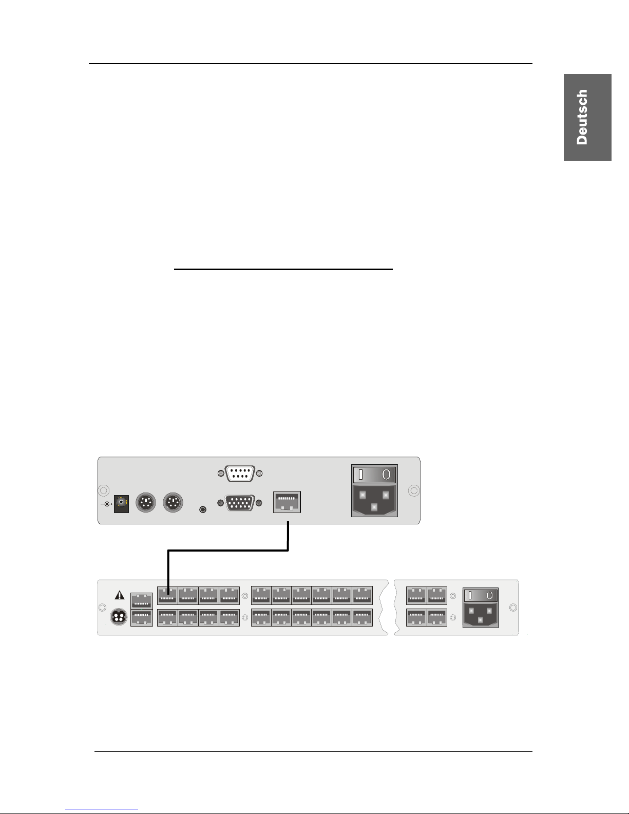
2.2.2 Konsolenanschluss über UCON-a
Die Bedienkonsole UCON-a verbinden Sie mit einem von G&D bestellbaren
Übertragungskabel K-C7-x mit dem CATCenter. Die Distanz zwischen
CATpro2 und UCON-a kann bis zu 100 Meter betragen. Die Distanz zum
CATCenter beträgt maximal 10 Meter.
Bei Verwendung anderer Kabel (z. B. vorhandenes CAT-5-Kabel), ist die Länge
abhängig von der Qualität des eingesetzten Kabels.
• Stecken Sie hierzu das eine Ende des Übertragungskabels in die
Schnittstelle Transmisson des UCON-a.
• Das andere Ende des Übertragungskabels stecken Sie in die
gewünschte Console-Schnittstelle (RJ45-Buchse) des CATCenters.
Link
5V DC/5A
Monitor Red. Power
Main Power
A
C 100-240 V, 47-63 Hz
Transmission
Keyb . Mous ePS/2 Service
UCON-a
CAT-x-Kabel
CATCenter
12V DC/3A Network A
Network B
56
7
8Console
12
3
4Console
12
3
4
5 6 15 16
17
18 19 20
21 22
31 32
Red.
Power
Main Power
AC 100-240 V, 47-63 Hz
6
7
2
3
Read instruction
carefully before
installing!
Avoid misuse!
KVM Switch.
Zum Anschluss der lokalen Konsole am UCON-a verfahren Sie wie folgt:
• Schließen Sie die Mouse an die Buchse PS/2 Mouse an.
• Schließen Sie das Keyboard an die Buchse Keyb. an.
• Schließen Sie Ihren Monitor an die Buchse Monitor an.
Page 14

Guntermann & Drunck GmbH Installationsanleitung CATCenter
Seite 14
Alternativ kann an den Schnittstellen für die lokale Konsole auch das AcxosSystem an dem UCON-a angeschlossen werden. Verfahren Sie wie folgt:
• Verbinden Sie den 25-pol. Sub-D-Stecker des mitgelieferten CCP-x-
Kabels mit der Schnittstelle KVM In des Acxos-Systems.
• Stellen Sie nun mittels der beiden PS/2-Stecker des CCP-x-Kabels die
Verbindung zur Keyboard- und Mouseschnittstelle des UCON-a her.
Die beiden Stecker sind mit entsprechenden Symbolen versehen.
• Stecken Sie den 15-pol. Sub-HD-Stecker des mitgelieferten CCP-x-
Kabels in die Monitor-Schnittstelle des UCON-a.
• Die Schnittstelle LINK dient dem Anschluss der seriellen
Direktkopplung mit dem System Acxos. Stecken Sie hierzu den Sub-D
9-Stecker in die Link-Schnittstelle (Sub-D-9-Buchse) des Acxos und
verbinden Sie diese mit der Schnittstelle LINK des UCON-a.
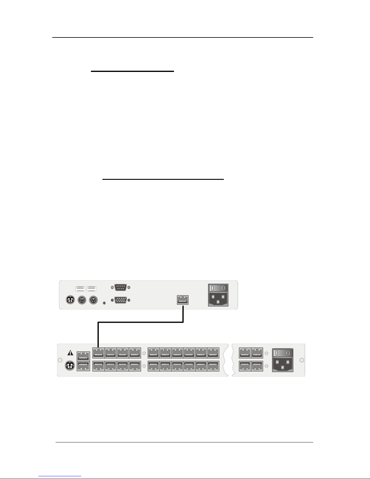
2.2.3 Anschluss des UCON-s
2.2.3.1 Konsolenanschluss
Die Bedienkonsole UCON-s verbinden Sie mit einem von G&D gestellten
Übertragungskabel K-C7/LD-x mit dem CATCenter. Die Distanz zwischen
CATpro2 und UCON-s kann bis zu 300 Meter betragen. Bei Verwendung
anderer Kabel (z. B. vorhandenes CAT-5-Kabel), ist die Länge abhängig von
der Qualität des eingesetzten Kabels.
• Stecken Sie hierzu das eine Ende des Übertragungskabels in die
Schnittstelle Transmission des UCON-s.
• Das andere Ende des Übertragungskabels stecken Sie in die
gewünschte Console-Schnittstelle (RJ45-Buchse) des CATCenters.
Mouse Keyb.
USB
Keyb. Mouse
PS/2
Main Power
AC 100-240 V, 47-63 Hz
Monitor PC 1 PC 2Service Transmission12V DC/1,2A
Red. Power
UCON-s
CAT-x-Kabel
CATCenter
12V DC/3A Network A
Network B
56
7
8Console
12
3
4Console
12
3
4
5 6 15 16
17
18 19 20
21 22
31 32
Red.
Power
Main Power
AC 100-240 V, 47-63 Hz
6
7
2
3
Read instruction
carefully before
installing!
Avoid misuse!
KVM Switch.
• Stecken Sie Keyboard und Mouse Ihres Arbeitsplatzes in die
entsprechenden Buchsen des UCON-s. Schließen Sie den Monitor an
der Schnittstelle Monitor auf der Geräterückseite an.
Page 15

Guntermann & Drunck GmbH Installationsanleitung CATCenter
Seite 15
• Optional haben Sie die Möglichkeit, Keyboard und Mouse über USB
anzuschließen. Verbinden Sie dazu Keyboard und/oder Mouse mit
den Schnittstellen des UCON-s. Wählen Sie einen reinen USBBetrieb, so hat dieser den Vorrang vor dem PS/2-Anschluss. Ein
gemischter Betrieb (z. B. einmal PS/2-Mouse und USB-Keyboard) ist
auch möglich.
2.2.3.2 Anschluss der lokalen Targets
Zum Anschluss der lokalen Targets verfahren Sie bitte wie folgt:
• Monitor-, Keyboard- und Mousekabel von den Targets abziehen.
• Monitor
:
Stecken Sie den 15-pol. Sub-HD-Stecker des CPU-Anschlussdongle
CATpro2 in die VGA-Schnittstelle des anzuschließenden Targets.
• Keyboard/Mouse:
Stecken Sie nun die beiden PS/2-Stecker des CPU-Anschlussdongle
CATpro2 in die Keyboard- und Mouseschnittstelle des
anzuschließenden Targets. Die beiden Stecker sind mit
entsprechenden Symbolen versehen und farbig kodiert.
• Stecken Sie nun das eine Ende des Anschlusskabels PRO-x (x =
gelieferte Länge) in die RJ45-Schnittstelle des CATpro2.
• Verbinden Sie danach das andere Ende des Anschlusskabels PRO-x
(x = gelieferte Länge) in die gewünschte TARGET-Schnittstelle (RJ45Buchse) des UCON-s.
2.2.3.3 Umschaltung zwischen lokalen Targets und CATCenter
Zur Umschaltung zwischen den am UCON-s angeschlossenen lokalen Targets
und dem Aufschalten auf das CATCenter-System stehen Ihnen wahlweise die
Taster an der Frontseite des UCON-s oder konfigurierbare Tastenkombinationen zur Verfügung.
Page 16

Guntermann & Drunck GmbH Installationsanleitung CATCenter
Seite 16
a. Verwendung der Taster am UCON-s
Red.
Main
Active
Status
RemotePower
Status
Active
PC 1 PC 2 Trans
Die Taster der Frontseite haben folgende Bedeutung:
PC 1: Aufschalten auf das erste lokale Target
PC 2: Aufschalten auf das zweite lokale Target
Trans: Mit diesem Schalter wird die Transmission-Schnittstelle auf der
Rückseite des UCON-s angesprochen (vgl. Kap. 2.2.3.1). Sie
stellen über diesen Taster die direkte Verbindung zum CATCenter
her. Im Anschluss stehen Ihnen alle weiteren Bedienschritte zur
Verfügung, wie ab Kap. 2 des Bedienungs-Handbuches
beschrieben.
b. Verwendung der konfigurierbaren Tastenkombinationen
Hinweis:
Die Tastenkombinationen bestehen aus einem Hotkey und einem Selectkey,
welche gleichzeitig auf dem angeschlossenen Keyboard zu betätigen sind.
Der zu betätigende Hotkey wird durch die Konfiguration von CATCenter
bestimmt. Im Auslieferungszustand des CATCenters ist die Taste STRG als
Hotkey-Taste voreingestellt. Falls die Konfiguration des angeschlossenen
CATCenters eine andere Hotkey-Taste anstelle der STRG-Taste vorsieht, ist
diese zu betätigen.
Die in der folgenden Tabelle aufgeführten Tastenkombinationen zur Umschaltung zwischen den lokalen Targets und CATCenter sind werkseitig
voreingestellt:
Hotkey Selectkey Funktion
STRG + F1 Aufschalten auf das erste lokale Target
STRG + F2 Aufschalten auf das zweite lokale Target
STRG + F3 Mit dieser Tastenkombination wird die Trans-
mission-Schnittstelle auf der Rückseite des
UCON-s angesprochen (vgl. Kap. 2.2.3.1).
Diese Tastenkombinationen können vom Anwender – innerhalb eines vorgegebenen Rahmens – im OSD konfiguriert werden. Detaillierte Informationen
hierzu werden im folgenden Abschnitt erläutert.
Page 17

Guntermann & Drunck GmbH Installationsanleitung CATCenter
Seite 17
Änderung des voreingestellten Selectkeys und Aufruf der Mouse-Utilities
Die im UCON-s vom Anwender durchgeführten Änderungen der StandardKonfiguration sind ausschließlich für das konfigurierte Gerät gültig, da diese
Einstellungen unabhängig von den Systemeinstellungen des CATCenters sind.
Die folgenden Arbeitsschritte sind daher an jedem angeschlossenen UCON-s
separat durchzuführen.
Anzeige und Bedienung des OSD des UCON-s:
Voraussetzung für den Aufruf des OSD ist, dass der erste oder zweite Kanal
auf das UCON-s aufgeschaltet ist. Verfahren Sie daher zunächst wie oben
beschrieben, um einen dieser beiden Kanäle aufzuschalten.
Um das OSD auf dem Monitor der Konsole anzuzeigen, betätigen Sie den im
CATCenter definierten Hotkey (Standardeinstellung: STRG) und die Taste
NUM. Die Navigation im OSD ist anschließend über die Pfeiltasten
AUFWÄRTS und ABWÄRTS des Keyboards oder das Scrollrad der Mouse der
Konsole möglich.
Die Bedienung der einzelnen Einträge wird in den folgenden Abschnitten
beschrieben.
Nach der Änderung von Einstellungen ist die F2-Taste zu betätigen, um die
Einstellungen zu speichern.
Auswahl eines benutzerdefinierten Selectkeys:
Der Eintrag SELECTKEY im OSD bietet die Möglichkeit zwischen folgenden
möglichen Tasten zu wählen:
Menüauswahl Art der Tasten
1 - 3 Zifferntasten 1, 2, und 3 des alphanumerischen
Tastenblocks
NUM1 - NUM3 Zifferntasten 1, 2 und 3 des numerischen Tastenblocks
a-c Buchstaben a, b, c der Tastatur
F1 - F3 Funktionstasten F1, F2, F3 der Tastatur
Um die aktuelle Einstellung im UCON-s zu ändern, markieren Sie den Eintrag
SELECTKEY des OSD und betätigen anschließend die Taste SPACE um
zwischen den verschiedenen Wahlmöglichkeiten umzuschalten.
Bei der Auswahl der Tasten ist zu bedenken, dass das durch UCON-s zu
bedienende CATCenter ebenfalls die Verwendung von Hotkeys (s. Seite 40ff.
der Bedienungsanleitung) zur Umschaltung zwischen den verschiedenen, am
Page 18

Guntermann & Drunck GmbH Installationsanleitung CATCenter
Seite 18
CATCenter angeschlossenen, Target-Rechnern erlaubt. Hierfür stehen die
gleichen Arten von Tasten zur Verfügung, wie sie oben aufgelistet sind.
Wichtig:
Die im CATCenter systemweit konfigurierten Selectkeys sind bei Änderungen
des lokalen Selectkeys im OSD des UCON-s nicht verfügbar, um Einschränkungen in der Bedienbarkeit des CATCenters zu vermeiden. Wurden im
CATCenter die Zifferntasten 0 bis 9 als Selectkeys ausgewählt so ist der die
Auswahl 1-3 im UCON-s nicht möglich.
Falls es – beispielsweise aufgrund der nachträglichen Änderung des Select–
keys des CATCenters – zur Verwendung der gleichen Tasten zur Bedienung
und Konfiguration des CATCenters und des UCON-s kommt, ist der Selectkey
des UCON-s wie oben beschrieben zu ändern.
Aufruf der Mouse-Utilities:
Falls die Mouse während des Betriebs oder nach Wartungsarbeiten nicht
ordnungsgemäß funktioniert, kann mit den Mouse-Utilities für schnelle Abhilfe
gesorgt werden. Diese sind durch Auswahl des Eintrags MOUSE UTILITIES
des OSD und Betätigen der ENTER-Taste oder Verwendung der linken MouseTaste aktivierbar.
Die Funktionen der Mouse-Utilities werden auf Seite 32f. der Bedienanleitung
ausführlich beschrieben.
2.2.4 Anschluss des UCON-IP-eco
2.2.4.1 Verbindung mit dem CATCenter
Für die Installation des UCON-IP-eco an einem CATCenter beachten Sie bitte
folgende Installationsschritte:
1) Aufstellen des UCON-IP-eco im 19“-Rack
Bitte beachten Sie, dass alle Schnittstellen von UCON-IP-eco leicht zugänglich
sind und es zu keinem Hitzestau kommt. Die höchste zulässige
Betriebstemperatur liegt bei 40 °C.
2) Verbinden des UCON-IP-eco mit dem CATCenter
Der UCON-IP-eco wird über ein CAT-x-Kabel mit einem freien Konsolenport
des CATCenter verbunden.
Page 19

Guntermann & Drunck GmbH Installationsanleitung CATCenter
Seite 19
Keyb. MousePS/2
Monitor
12VDC/5AEthernet
COM 1
Red. Power
M
a
i
n
P
o
w
e
r
1
0
0
-
2
4
0
V
/
6
0
-
5
0
H
z
/
0
.
4
-
0
.
2
A
Trans mis si on
12V DC/3A Network A
Network B
56 78Console
12
3
4Console
1234
5678CPU910 11 12 13 14 15 16
17 18 19 20 21 22 23 24 CPU 25 26 27 28 29 30 31 32
Red.
Power
Main Power
AC 100-240 V, 47-63 Hz
67
2
3
Read instruction
carefully before
installing!
Avoid misuse!
KVM Switch.
2.2.4.2 Anschluss der lokalen Konsole
Für den Anschluss der lokalen Konsole am UCON-IP-eco beachten Sie bitte
folgende Installationsschritte:
Keyb. MousePS/2
Monitor
12VDC/5AEthernet
COM 1
Red. Power
M
a
i
n
P
o
w
e
r
1
0
0
-
2
4
0
V
/
6
0
-
5
0
H
z
/
0
.
4
-
0
.
2
A
Trans mis si on
• Schließen Sie die Mouse an die Buchse PS/2 Mouse an.
• Schließen Sie das Keyboard an die Buchse Keyb. an.
• Schließen Sie Ihren Monitor an die Buchse Monitor an.
2.2.5 Anschluss des UCON-IP
2.2.5.1 Verbindung mit dem CATCenter
Für die Installation des UCON-IP-Systems an einem CATCenter beachten Sie
bitte folgende Installationsschritte:
1) Aufstellen des UCON-IP-System im 19“-Rack
Bitte beachten Sie, dass alle Schnittstellen von UCON-IP leicht zugänglich sind
und es zu keinem Hitzestau kommt. Die höchste zulässige Betriebstemperatur
liegt bei 45° C.
2) Verbinden des UCON-IP-System mit dem CATCenter
Der UCON-IP wird über das Anschlusskabel K-C7-1 mit einem freien
Konsolenport des CATCenter verbunden.
Verbindung über ein CAT-x-Kabel
Page 20

Guntermann & Drunck GmbH Installationsanleitung CATCenter
Seite 20
12V DC/5A
USB
Keyb. Mouse
PS/2
Ethernet A Ethernet B
Service
ISDN
COM 1 Red. Power
Main Power
A
C 100-240 V, 47-63 Hz
TransmissionMonitor
12V DC/3A Network A
Network B
56 78Console
12
3
4Console
1234
5678CPU910 11 12 13 14 15 16
17 18 19 20 21 22 23 24 CPU 25 26 27 28 29 30 31 32
Red.
Power
Main Power
AC 100-240 V, 47-63 Hz
67
2
3
Read instruction
carefully before
installing!
Avoid misuse!
KVM Switch.
2.2.5.2 Anschluss der lokalen Konsole
Für den Anschluss der lokalen Konsole am UCON-IP-System beachten Sie
bitte folgende Installationsschritte:
12V DC/5A
USB
Keyb. Mouse
PS/2
Ethernet A Ethernet B
Service
ISDN
COM 1 Red. Power
Main Power
A
C 100-240 V, 47-63 Hz
TransmissionMonitor
• Schließen Sie die Mouse an der Buchse PS/2 Mouse an.
• Schließen Sie das Keyboard an der Buchse Keyb. an.
• Schließen Sie Ihren Monitor an der Buchse Monitor an.
2.2.5.3 Anschluss an eine ISDN-Anlage
Wenn Sie das UCON-IP über ISDN erreichen wollen, müssen Sie das UCONIP mit Ihrer Telefonanlage verbinden.
12V DC/5A
USB
Keyb. Mouse
PS/2
Ethernet A Ethernet B
Service
ISDN
COM 1 Red. Power
Main Power
A
C 100-240 V, 47-63 Hz
TransmissionMonitor
Verwenden Sie hierzu ein CAT-x-basiertes Patchkabel. Stecken Sie das eine
Ende (RJ45-Stecker) in die Schnittstelle ISDN des UCON-IP und das andere
Ende (RJ45-Stecker) in einen SO-Bus (Protokolltyp EURO-ISDN) Ihrer TKAnlage.
Verbindung über ein CAT-x-Kabel
Page 21

Guntermann & Drunck GmbH Installationsanleitung CATCenter
Seite 21
2.3 Netzwerkschnittstellen
Über die auf der Rückseite des CATCenters befindlichen Netzwerkschnittstellen können Sie bestimmte Netzwerkfunktionalitäten erreichen. Diese
wären:
• Durchführung der CATCenter-Netzwerkkonfiguration
• Authentifizierung gegenüber LDAP, Active Directory, RADIUS
• Zeitanpassung über einen NTP-Server
• Versendung von Log-Meldungen an Syslog-Server
• Durchführung von Firmwareupdate und Backup
Für diese hier aufgeführten Punkte gibt es die CATCenter Xview-Software. Diese
Software wird in einem gesonderten Handbuch beschrieben!
2.4 Stromversorgung
Schließen Sie die mitgelieferten Kaltgerätekabel an den Kaltgerätebuchsen
Main POWER der Geräte (CATCenter, UCON, UCON-a, UCON-s, UCON-IPeco & UCON-IP) an.
Optional kann über die Buchse Red. Power ein redundantes Netzteil
angeschlossen werden. Verwenden Sie dazu das optional erhältliche
Tischnetzteil Power-Set-X/TypX (Typ abhängig vom bestellten Gerät).
2.5 Installation der Erweiterungseinheit
Durch Kaskadierung kann die Anzahl der anschließbaren Targets auf 512
(1024, 2048) erhöht werden. Diese Targetanzahl wird innerhalb von zwei
Kaskadenstufen erreicht.
Innerhalb der ersten Kaskadenstufe lassen sich 128 Targets anschließen.
Durch die zweite Kaskadenstufe wird die maximale Targetanzahl von 512
erreicht.
Für eine Kaskadierung, müssen die CATCenter Geräte miteinander verbunden
werden.
Page 22

Guntermann & Drunck GmbH Installationsanleitung CATCenter
Seite 22
Um eine Verbindung zwischen zwei CATCenter herzustellen, können Sie ein
herkömmliches CAT-Kabel verwenden. Aus unserem Hause empfehlen wir
hierfür
• bei einer zu überbrückenden Länge von bis zu 20 Meter PRO-X-Kabel
• ab einer Länge von 20 Meter K-C7/LD-x-Kabel.
Bitte beachten Sie, dass die Gesamtlänge zwischen CATpro2 und UCON-a
100 Meter, bzw. 300 Meter für UCON und UCON-s nicht überschreitet.
Im Weiteren wird bei dieser Installationsbeschreibung von einem CAT-Kabel
gesprochen.
Im Mastergerät stehen zur Kaskadierung insgesamt 32 CPU-Ports zur
Verfügung. Geht man davon aus, dass am Mastergerät 8 Konsolen
angeschlossen sind, die weiterhin auf alle Targets zugreifen sollen, so muss für
jeden Konsolenanschluss ein CPU-Port für die Kaskade verwendet werden.
Somit müssen am Mastergerät 8 CPU-Ports belegt werden, damit alle 8
Konsolen weiterhin auf alle angeschlossenen Targets zugreifen können.
Haben Sie dagegen nur einen Konsolenzugriff, so müssen Sie, analog zu dem
oben beschriebenen Verfahren, einen CPU-Port am Master bereitstellen.
Generell gilt: Für jeden Konsolenzugriff, der am Slave realisiert
werden soll, muss am Master die gleiche Anzahl von CPU-Ports
zur Verfügung gestellt werden!
Die 32 CPU-Ports des Mastergerätes lassen sich entsprechend dieser
Systematik auf der Rückseite des CATCenters in folgende Bereiche für eine
Kaskadierung aufteilen (diese Einteilung ist als Empfehlung zu verstehen):
• CPU Ports 1 - 8 ermöglicht den Anschluss eines ersten
Slavegerätes innerhalb der ersten Kaskadestufe
• CPU Ports 9 - 16 ermöglicht den Anschluss eines zweiten
Slavegerätes innerhalb der ersten Kaskadestufe
• CPU Ports 17 - 24 ermöglicht den Anschluss eines dritten
Slavegerätes innerhalb der ersten Kaskadestufe
• CPU Ports 25 - 32 ermöglicht den Anschluss eines vierten
Slavegerätes innerhalb der ersten Kaskadestufe
Hinweis:
Die hier erwähnte CPU-Zuordnung innerhalb eines CPU-Port-Bereiches
dient der Übersichtlichkeit während und nach der Kaskadierung. Sie
können jedoch ein Slavegeräte mit jedem beliebigen CPU-Port des
Mastergerätes verbinden.
Page 23

Guntermann & Drunck GmbH Installationsanleitung CATCenter
Seite 23
Wie der Anschluss eines ersten Slavegerätes innerhalb der ersten
Kaskadenstufe am Mastergerät erfolgt, verdeutlicht dass nachfolgende
Schaubild.
Mastergerät
5
678Console
12 3 4Console 1 2 3 4 5 6 7 8CPU9 10111213141516
17 18
19
20
21 22
23
24 CPU
25 26
27
28
29 30
31
32 Main Po wer
A
C 100-240 V, 47-6 3 Hz
5V DC/5A Network A
Network B
Read instruction
carefully before
installing!
Avoid misuse!
KVM Switch.
Red.
Power
56 78Console
1
234Console 1 2 3 4 5 6 7 8CPU9 10111213141516
17 18 19 20 21 22 23 24 C PU 25 26 27 28 29 30 31 32
Main Po wer
AC 100-240 V, 47-63 Hz
5V DC/5A Network A
Network B
Read instruc tion
carefully before
installing!
Avoid misuse!
KVM Switch.
Red.
Power
1111 1111
4444 4444
22
2
22222
3333 3333
Hier werden die CPU-Ports 1 - 8 über jeweils ein CAT-Kabel (somit insgesamt
acht CAT-Kabel) mit dem Slavegerät verbunden. Dieses CAT-Kabel wird im
Slavegerät in die RJ45-Buchsen für den Konsolenanschluss gesteckt.
Möchten Sie nun ein zweites Slavegerät am Mastergerät anschließen, so
nehmen Sie hierzu die CPU-Ports 9 - 16 und verbinden diese Ports ebenfalls
mit den Konsolenports des zweiten Slavegerätes.
Für den Anschluss der dritten und vierten Slavegeräte verfahren Sie genauso.
Bei einer Komplettbelegung des Mastergerätes mit vier Slavegeräten können
am Mastergerät keine Targets angeschlossen werden.
Beabsichtigen Sie nun mehr als 128 Targets anzuschließen, geschieht dieses
über die zweite Kaskadenstufe. Hier müssen ebenfalls CATCenter miteinander
verbunden werden. Diese werden jedoch nicht mit dem Mastergerät
verbunden, sondern mit den CATCenter der ersten Kaskadestufe.
Slavegerät der
ersten Kaskadestufe
Page 24

Guntermann & Drunck GmbH Installationsanleitung CATCenter
Seite 24
Das Anschlussverfahren zwischen diesen CATCenter entspricht exakt dem
zuvor beschriebenen Verfahren.
Mastergerät
5
678Console
1234Console 1 2 3 4 5 6 7 8 CPU 9 10 11 12 13 14 15 16
17 18
19
20
21 22
23
24 CPU
25 26
27
28
29 30
31
32 Main Power
A
C 100-240 V, 47-63 Hz
5V DC/5A Network A
Network B
Read instruction
carefully before
install ing!
Avoid misuse!
KVM Switch.
Red.
Power
5
678Consol e
1
234Consol e 1 2
3
4
5678CPU
9101112
13 14
15
16
17 18 19 20 21 22 23 24 CPU 25 26 27 28 29 30 31 32
Main Power
A
C 100-240 V, 47-63 Hz
5V DC/5A Network A
Network B
Read instruction
carefully before
installing!
Avoid misuse!
KVM Switch.
Red.
Power
56 78Console
1
234Console 12345678CPU910111213141516
17 18 19 20 21 22 23 24 CPU 25 26 27 28 29 30 3 1 32
Main Power
AC 100-240 V, 47-63 Hz
5V DC/5A Network A
Network B
Read instruction
carefully before
installing!
Avoid misuse!
KVM Switch.
Red.
Power
1111 1111
4444 4444
22
2
22222
3333 3333
Der Anschluss der Targets an die Slavegeräte erfolgt analog zu dem in Kapitel
2.1 beschriebenen Verfahren.
Gemäß dieser zuvor beschriebenen Verfahrensweise, lassen sich alle
CATCenter-Produkte miteinander kombinieren. So können
• CATCenterX8 – Master mit CATCenterX4 – Slave,
• CATCenterX8 – Master mit CATCenterX2 – Slave,
• CATCenterX4 – Master mit CATCenterX4 – Slave,
• CATCenterX4 – Master mit CATCenterX2 – Slave,
• CATCenterX2 – Master mit CATCenterX2 – Slave,
kombiniert werden.
Bei all diesen Kombinationen ist immer zu beachten, dass für die gewünschte
Anzahl von Konsolzugriffen (z. B. bei einem CATCenterX2-Slave max. 2
Konsolen) am Master die entsprechend gleiche Anzahl an CPU-Ports bereit
gestellt werden muss (bei einem CATCenterX2-Slave und gewünschten zwei
Konsolenzugriffe somit 2 CPU-Ports am CATCenter-Master).
Hinweis:
Lesen Sie ergänzend hierzu bitte auch das Kapitel 5.8.7 der Bedienungsanleitung.
Slavegerät der 1.
Kaskadestufe
Slavegerät der 2.
Kaskadestufe
Page 25

Guntermann & Drunck GmbH Installationsanleitung CATCenter
Seite 25
2.6 Installation des HardBoot CCX
Für die Beschreibung der Installation des HardBoot CCX verweisen wir auf das
entsprechende Handbuch „Hardboot_CCX“.
3 Netzwerkanschluss – IP Erstkonfiguration
Damit der CATCenter im Netzwerk erreichbar ist, können Sie im NETWORK-
Submenü die Netzwerkeinstellungen für Ihren CATCenter X8 durchführen.
Melden Sie sich hierzu mit dem Adminstrator-Loginnamen und Passwort an.
Dieses Passwort finden Sie in Kapitel 6.
In dem sich anschließend öffnenden SELECT-Menü drücken Sie die F11Taste. Das CONFIGURATION-Menü öffnet sich. Fahren Sie im
CONFIGURATION-Menü mit den PFEIL AUF bzw. PFEIL AB – Tasten des
Keyboard oder der Mouse auf den Eintrag Network und drücken Sie dann die
ENTER -Taste. Es öffnet sich ein Untermenü, welches Ihnen folgende
Einstellmöglichkeiten bietet:
Network Management
Global
Network A
Network B
ESC
Innerhalb dieses Menüs können Sie einstellen:
• über welchen Gateway der CATCenter X8 erreichbar sein soll und
• welche IP-Adressen sowohl Network A & Network B (vorzufinden auf
der Rückseite des CATCenter X8 besitzen.
Zusätzlich können Sie diese Einstellungen über die im Lieferumfang enthaltene
Toolware „CATCenter Xview“ (vgl. Handbuch CATCenter Xview) durchführen.
Mit der ESC-Taste verlassen Sie dieses Menü.
Page 26

Guntermann & Drunck GmbH Installationsanleitung CATCenter
Seite 26
3.1.1 Definition des Gateway
Damit der CATCenter X8 in komplexeren Netzwerken aus allen Teilnetzwerken
erreichbar ist, muss der Standard-Gateway definiert werden.
Fahren Sie dazu im NETWORK MANAGEMENT-Submenü mit den PFEIL
AUF bzw. PFEIL AB–Tasten des Keyboards oder der Mouse auf den Eintrag
GATEWAY und drücken Sie dann die ENTER-Taste. Es öffnet sich folgendes
Fenster.
Edit Network Global
Gateway 192.XXX.XXX.XXX
ESC F2: Save
Tragen Sie nun in der Zeile Gateway die IP-Adresse des Gateways ein.
Steppen Sie dazu entweder mit den Pfeil rechts/Pfeil links-Tasten oder der
TAB-Taste auf einer der vier Felder. Durch Drücken der ENTER-Taste setzten
Sie jedes einzelne Feld in den Editiermodus und die Schriftfarbe wechselt zu
gelb.
Alle bis zu diesem Zeitpunkt durchgeführten Editierarbeiten werden durch
Drücken der F2-Taste gespeichert.
Mit der ESC-Taste verlassen Sie dieses Menü, ohne die getroffenen
Änderungen zu speichern. Auf diesen Zustand werden Sie über eine
Sicherheitsabfrage hingewiesen.
Warning
You did not save your changes!
Press
F2 to save and exit
ENTER to exit without saving
ESC to cancel
F2 : Save and exit
Enter : Exit without saving
ESC: Cancel
Um Ihre Einstellung dauerhaft zu speichern, drücken Sie die F2-Taste. Sie
kehren zurück in das NETWORK MANAGEMENT-Submenü.
Page 27

Guntermann & Drunck GmbH Installationsanleitung CATCenter
Seite 27
3.1.2 Definition des Netzwerkparamater für Network A bzw. B
Als letzte Netzwerkeinstellung muss mind. einer der auf der Rückseite des
CATCenter X8 vorhandene Netzwerkschnittstelle eindeutige Vorgaben (z. B.
Vergabe einer IP-Adresse) getroffen werden, damit der CATCenter X8 auch
erreichbar ist
Der CATCenter X8 verfügt auf der Rückseite über zwei Netzwerkschnittstellen.
12V DC/3A Network A
Network B
56 78Console
12
3
4Console
1234
5678CPU910 11 12 13 14 15 16
17 18 19 20 21 22 23 24 CPU 25 26 27 28 29 30 31 32
Red.
Power
Main Power
AC 100-240 V, 47-63 Hz
67
2
3
Read instruction
carefully before
installing!
Avoid misuse!
KVM Switch.
Beachten Sie bitte, dass Einstellungen in dem Bereich „Network A“ nur
Auswirkungen haben auf die physikalische Schnittstelle „Network A“ am
CATCenter X8.
Da die Einstellungen für die Einträge Network A und Network B identisch sind,
wird im Weiteren die Einstellung beispielhaft für den Eintrag Network A
erläutert.
Fahren Sie dazu im NETWORK MANAGEMENT-Submenü mit den PFEIL
AUF bzw. PFEIL AB–Tasten des Keyboards oder der Mouse auf den Eintrag
INTERFACE A und drücken Sie dann die ENTER-Taste. Es öffnet sich
folgendes Fenster.
Edit Network A
MAC address 00:0F:F4:00:00:18
Assignment static
Address 192.XXX.XXX.XXX
Netmask 255. 255. 255.0
Connection A u t o
ESC F2: Save
In der zweiten Zeile des Headers finden Sie die MAC-Adresse der
Netzwerkschnittstelle Network A. Diese ist nicht veränderbar.
Im Feld Assignment bestimmen Sie, ob der CATCenter X8:
• eine statische IP-Adresse (static) oder
• eine dynamische IP-Adresse (DHCP) oder
• keine IP-Adresse (off)
erhalten soll.
Page 28

Guntermann & Drunck GmbH Installationsanleitung CATCenter
Seite 28
Mit der Space-Taste (toggle) können Sie nun zwischen den 3 Einträgen:
• static
• DHCP
• Off
wählen.
Die beiden nachfolgenden Einträge sind nur dann erreichbar, wenn Sie denn
Definition static wählen.
Hinweis:
Im Auslieferungszustand ist die IP-Adresse 192.168.0.10 eingetragen.
Im Feld Address vergeben Sie die statische IP-Adresse des CATCenter X8.
Steppen Sie dazu entweder mit den Pfeil rechts/Pfeil links-Tasten oder der
TAB-Taste auf einer der vier Felder. Durch Drücken der ENTER-Taste setzten
Sie jedes einzelne Feld in den Editiermodus und die Schriftfarbe wechselt zu
gelb.
Im Feld Netmask tragen Sie die Netzmaske ein. Standardmäßig ist dies
255.255.255.0. Steppen Sie dazu entweder mit den Pfeil rechts/Pfeil linksTasten oder der TAB-Taste auf einer der vier Felder. Durch Drücken der
ENTER-Taste setzten Sie jedes einzelne Feld in den Editiermodus und die
Schriftfarbe wechselt zu gelb.
Im Feld Connection bestimmen Sie die Ethernet Verbindungsgeschwindigkeit
und den Modus.
Zur Auswahl stehen:
• manuelle Festlegung der Ethernet Verbindungsgeschwindigkeit und
die Modi (100MBit full-duplex, 100MBit half-duplex, 10MBit full-
duplex, 10MBit half-d uplex)
• die Netzwerkschnittstelle und die Gegenstelle (zweiter Rechner, Hub,
Switch) handeln die Geschwindigkeit untereinander aus (Auto;
Default-Einstellung)
Hinweis:
Das Kommunikationsverhalten kann durch den Einsatz verschiedener
Netzwerkkomponenten negativ beeinflusst werden. So führt beispielsweise die
Einstellung „Auto“ je nach Hersteller nicht zu einem zufrieden stellenden
Ergebnis.
Alle bis zu diesem Zeitpunkt durchgeführten Editierarbeiten werden durch
Drücken der F2-Taste gespeichert.
Page 29

Guntermann & Drunck GmbH Installationsanleitung CATCenter
Seite 29
Mit der ESC-Taste verlassen Sie dieses Menü, ohne die getroffenen
Änderungen zu speichern. Auf diesen Zustand werden Sie über eine
Sicherheitsabfrage hingewiesen.
Warning
You did not save your changes!
Press
F2 to save and exit
ENTER to exit without saving
ESC to cancel
F2 : Save and exit
Enter : Exit without saving
ESC: Cancel
Um Ihre Einstellung dauerhaft zu speichern, drücken Sie die F2-Taste. Sie
kehren zurück in das NETWORK MANAGEMENT-Submenü.
Page 30

Guntermann & Drunck GmbH Installationsanleitung CATCenter
Seite 30
4 LED-Anzeigen
4.1 CATCenter
4.1.1 Frontseite
Nach dem Anschluss des Kaltgerätekabels schalten Sie den CATCenter über
den Wippschalter auf der Rückseite des Gerätes ein. Die LEDs auf der
Frontseite des CATCenters haben folgende Bedeutung:
enter
Main
Status
RS232
Service
Power
Red.
Switch
Net
CATCenter
POWER Redundant Leuchtet, wenn ein externes Netzteil angeschlossen ist und 12V
liefert.
Main Leuchtet, wenn die Spannungsversorgung hergestellt ist.
Status Ready Blinkt unregelmäßig, wenn das Netzwerk-Subsystem läuft.
Erlischt, wenn keine Netzwerkfunktionalität unterstützt wird.
Switch Blinkt schnell, wenn das CATCenter-System arbeitet .
4.1.2 Rückseite
Auf der Rückseite existieren zu jeder einzelnen RJ45-Schnittstelle LEDs.
Diese LEDs haben folgende Bedeutung:
2 3 4 5 6 7 8 Server 9 10 11 12 13 14 15 16243Console11
56 7 8Console
17
18 19 20 21 22 23 24 25 26 27 28 29 30 31 32Server
Read instruction
carefully before
installing!
Avoid misuse!
KVM Switch.
Network A
Network B
12V DC/3A
Red.
Power
Konsolen LEDs CPU LEDs Netzwerk LEDs
gelb Port ist aktuell durch
einen Benutzer belegt.
Port ist aktuell durch
einen Benutzer belegt.
Leuchtet dauerhaft bei
einer Voll-DuplexVerbindung; Blinkt bei
einer Halb-DuplexVerbindung (Collision).
grün Verbindung zu einem
Arbeitsplatzmodul
(UCON)
Verbindung zu einem
CATpro2 besteht.
Zeigt den Verbindungsstatus an. Blinkt bei
Aktivität.
Page 31

Guntermann & Drunck GmbH Installationsanleitung CATCenter
Seite 31
4.2 UCON
4.2.1 Frontseite
Nach dem Anschluss des Steckernetzteils schalten Sie den UCON über den
Wippschalter auf der Rückseite des Gerätes ein. Die LEDs auf der Frontseite
des UCON haben folgende Bedeutung:
Red.
Main
Active
Status
RemotePower
UCON
POWER Redundant Leuchtet, wenn ein externes Netzteil angeschlossen ist und 12V
liefert.
Main Leuchtet, wenn Spannungsversorgung hergestellt ist.
Remote Active Leuchtet, wenn eine Tastatur initialisiert wurde.
Blinkt, wenn keine Tastatur initialisiert wurde.
Status Leuchtet immer.
4.2.2 Rückseite
Mouse Keyb.
100-240V/60-50Hz
0.2-0.1A
USB
Keyb. MousePS/2 Monitor
LED out
Tra ns mi ssi onService
12VDC/800mA
Red. Power
Auf der Rückseite existiert für die RJ45-Schnittstelle LEDs.
Diese LEDs haben folgende Bedeutung:
CPU LEDs
gelb Port ist aktuell durch einen Benutzer belegt.
grün Verbindung zum CATCenter besteht.
Page 32
Guntermann & Drunck GmbH Installationsanleitung CATCenter
Seite 32
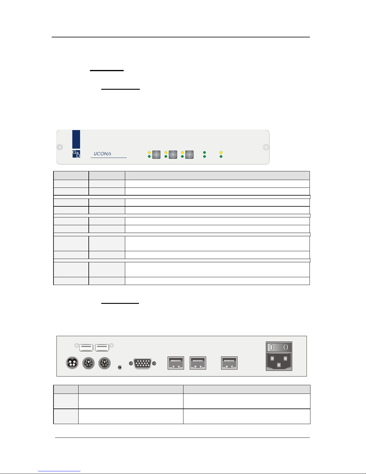
4.3 UCON-s
4.3.1 Frontseite
Nach dem Anschluss des Steckernetzteils schalten Sie den UCON-s über den
Wippschalter auf der Rückseite des Gerätes ein. Die LEDs auf der Frontseite
des UCON-s haben folgende Bedeutung:
Red.
Main
Active
Status
RemotePower
Status
Active
PC 1 PC 2 Trans
UCON-s
PC1 Active Leuchtet, wenn auf TARGET1 gearbeitet wird.
Status Leuchtet, wenn TARGET1 eingeschaltet ist.
PC2 Active Leuchtet, wenn auf TARGET2 gearbeitet wird.
Status Leuchtet, wenn TARGET2 eingeschaltet ist.
Trans Active Leuchtet, wenn auf den CATCenter zugegriffen wird.
Status Leuchtet, wenn CATCenter eingeschaltet ist.
Power Red. Leuchtet, wenn ein externes Netzteil angeschlossen ist und
12V liefert.
Main Leuchtet, wenn Spannungsversorgung hergestellt ist.
Remote Active Leuchtet, wenn eine Tastatur initialisiert wurde.
Blinkt, wenn keine Tastatur initialisiert wurde.
Status Leuchtet immer, wenn der CATCenter betriebsbereit ist.
4.3.2 Rückseite
Auf der Rückseite existieren zu jeder einzelnen RJ45-Schnittstelle LEDs.
Diese LEDs haben folgende Bedeutung:
Mouse Keyb.
USB
Keyb. Mouse
PS/2
Main Power
A
C 100-240 V, 47-63 Hz
Monitor PC 1 PC 2Service Transmission12V DC/1,2A
Red. Power
Transmission LEDs CPU LEDs
gelb Port ist aktuell durch einen
Benutzer belegt.
Port ist aktuell durch einen Benutzer
belegt.
grün Verbindung zum CATCenter
besteht.
Verbindung zu lokaler CPU über CATpro2
besteht.
Page 33

Guntermann & Drunck GmbH Installationsanleitung CATCenter
Seite 33
4.4 UCON-a
4.4.1 Frontseite
Nach dem Anschluss des Steckernetzteils schalten Sie den UCON-a über den
Wippschalter auf der Rückseite des Gerätes ein. Die LEDs auf der Frontseite
des UCON-a haben folgende Bedeutung:
Red.
Main
Active
Status
RemotePower
UCON-a
POWER Redundant Leuchtet, wenn ein externes Netzteil angeschlossen ist und 5V
liefert.
Main Leuchtet, wenn Spannungsversorgung hergestellt ist.
Remote Active Leuchtet, wenn eine Tastatur initialisiert wurde.
Blinkt, wenn keine Tastatur initialisiert wurde.
Status Leuchtet immer, wenn der CATCenter betriebsbereit ist.
4.4.2 Rückseite
Auf der Rückseite existiert für die RJ45-Schnittstelle LEDs.
Diese LEDs haben folgende Bedeutung:
Link
Keyb. M ousePS/2
5V DC/5A
Monitor Red. Power
Main Power
A
C 100-240 V, 47-63 Hz
Service Transmission
CPU LEDs
gelb Port ist aktuell durch einen Benutzer belegt.
grün Verbindung zum CATCenter besteht.
Page 34

Guntermann & Drunck GmbH Installationsanleitung CATCenter
Seite 34
4.5 UCON-IP-eco
4.5.1 Frontseite
Nach dem Anschluss des Steckernetzteils schalten Sie den UCON-IP-eco über
den Wippschalter auf der Rückseite des Gerätes ein. Die LEDs auf der
Frontseite des UCON-IP-eco haben folgende Bedeutung:
Red.
Main
Active
Status
SystemPower
UCON-IP
POWER Redundant Leuchtet, wenn ein externes Netzteil angeschlossen ist und 12V
liefert.
Main Leuchtet, wenn Spannungsversorgung hergestellt ist.
Remote Active Leuchtet, wenn eine Sitzung am UCON-IP gestartet wurde
Status Leuchtet immer, wenn der CATCenter betriebsbereit ist.
4.5.2 Rückseite
Auf der Rückseite existieren zu der Transmission- & Ethernet RJ45Schnittstelle LEDs. Diese LEDs haben folgende Bedeutung:
Keyb. MousePS/2
Monitor
12VDC/5AEthernet
COM 1
Red. Power
M
a
i
n
P
o
w
e
r
1
0
0
-
2
4
0
V
/
6
0
-
5
0
H
z
/
0
.
4
-
0
.
2
A
Trans mis si on
Transmission LEDs
gelb Port ist aktuell durch einen Benutzer belegt.
grün Verbindung zum CATCenter besteht.
Ethernet LEDs
gelb Leuchtet dauerhaft bei einer Voll-Duplex-Verbindung; Blinkt bei einer Halb-
Duplex-Verbindung (Collision).
grün Zeigt den Verbindungsstatus an. Blinkt bei Aktivität.
Page 35

Guntermann & Drunck GmbH Installationsanleitung CATCenter
Seite 35
4.6 UCON-IP
4.6.1 Frontseite
Nach dem Anschluss des Steckernetzteils schalten Sie den UCON-IP über den
Wippschalter auf der Rückseite des Gerätes ein. Die LEDs auf der Frontseite
des UCON-IP haben folgende Bedeutung:
Red.
Main
Active
Status
SystemPower
UCON-IP
POWER Redundant Leuchtet, wenn ein externes Netzteil angeschlossen ist und 12V
liefert.
Main Leuchtet, wenn Spannungsversorgung hergestellt ist.
Remote Active Leuchtet, wenn eine Sitzung am UCON-IP gestartet wurde
Status Leuchtet immer, wenn der CATCenter betriebsbereit ist.
4.6.2 Rückseite
Auf der Rückseite existieren zu der Transmission- & Ethernet RJ45Schnittstelle LEDs. Diese LEDs haben folgende Bedeutung:
12V DC/5A
USB
Keyb. Mouse
PS/2
Ethernet A Ethernet B
Service
ISDN
COM 1 Red. Power
Main Power
A
C 100-240 V, 47-63 Hz
TransmissionMonitor
Transmission LEDs
gelb Port ist aktuell durch einen Benutzer belegt.
grün Verbindung zum CATCenter besteht.
Ethernet LEDs
gelb Leuchtet dauerhaft bei einer Voll-Duplex-Verbindung; Blinkt bei einer Halb-
Duplex-Verbindung (Collision).
grün Zeigt den Verbindungsstatus an. Blinkt bei Aktivität.
Page 36

Guntermann & Drunck GmbH Installationsanleitung CATCenter
Seite 36
4.7 CATpro2- Reihe
Das Blinkverhalten der LEDs der CATpro2 hat folgende Bedeutung:
CATpro2
LED blinkt 3 mal pro
Sekunde
Keine Verbindung zu CATCenter
LED blitzt alle 1,5 Sek.
kurz auf
Verbindung zu CATCenter besteht, Target ist aber nicht
aufgeschaltet
LED leuchtet Verbindung zu CATCenter besteht und Target ist
aufgeschaltet
LED flackert Verbindung zu CATCenter besteht, Target ist
aufgeschaltet und Keyboard/Mouse-Daten werden
empfangen
Page 37

Guntermann & Drunck GmbH Installationsanleitung CATCenter
Seite 37
5 Technische Daten
5.1 CATCenter X2
Arbeitsplatz-Ports pro Gerät
2
Arbeitsplatz-Ports max. pro Cluster
16
Übertragungsart zum Arbeitsplatzmodul
dedizierte CAT-x-Verbindung
Target-Ports
16
Target-Ports Kaskadenstufe 1
128
Target-Ports Kaskadenstufe 2
1024
Übertragungsart zum Target-Modul
dedizierte CAT-x-Verbindung
Updateverfahren
lokale Servicebuchse
Netzwerkanschluss
nein
Stromversorgung
Main Typ internes Netzteil
Anschluss Kaltgerätestecker (IEC-320 C14)
Spannung
AC100-240V/60-50Hz 130 - 80 mA
Redundant Typ externes Netzteil
(optional) Anschluss miniDIN-4 Power-Buchse
Spannung +12VDC/1A
Gehäuse
Material Aluminium eloxiert
Dimensionen
Desktop 435 x 44 x 286 mm (B x H x T)
Rackmount
19” x 1HE x 286 mm (B x H x T)
Gewicht ca. 2,5 kg
Einsatzumgebung
Temperatur +5 bis +45 °C
Luftfeuchte < 80%, nicht kondensierend
Schnittstellen
zum Arbeitsplatzmodul RJ45 Buchse
zum Target-Modul RJ45 Buchse
für Update 2,5 mm Klinkenbuchse
für Power Switch RJ11 Buchse
Konformität
CE, RoHs
Page 38

Guntermann & Drunck GmbH Installationsanleitung CATCenter
Seite 38
5.2 CATCenter X4
Arbeitsplatz-Ports pro Gerät
4
Arbeitsplatz-Ports max. pro Cluster
32
Übertragungsart zum Arbeitsplatzmodul
dedizierte CAT-x-Verbindung
Target-Ports
32
Target-Ports Kaskadenstufe 1
256
Target-Ports Kaskadenstufe 2
2048
Übertragungsart zum Target-Modul
dedizierte CAT-x-Verbindung
Updateverfahren
lokale Servicebuchse
Netzwerkanschluss
nein
Stromversorgung
Main Typ internes Netzteil
Anschluss Kaltgerätestecker (IEC-320 C14)
Spannung
AC100-240V/60-50Hz 180 - 110 mA
Redundant Typ externes Netzteil
(optional) Anschluss miniDIN-4 Power-Buchse
Spannung +12VDC/2,3A
Gehäuse
Material Aluminium eloxiert
Dimensionen
Desktop 435 x 44 x 286 mm (B x H x T)
Rackmount
19” x 1HE x 286 mm (B x H x T)
Gewicht ca. 3,0 kg
Einsatzumgebung
Temperatur +5 bis +45 °C
Luftfeuchte < 80%, nicht kondensierend
Schnittstellen
zum Arbeitsplatzmodul RJ45 Buchse
zum Target-Modul RJ45 Buchse
für Update 2,5 mm Klinkenbuchse
für Power Switch RJ11 Buchse
Konformität
CE, RoHs
Page 39

Guntermann & Drunck GmbH Installationsanleitung CATCenter
Seite 39
5.3 CATCenter X8
Arbeitsplatz-Ports pro Gerät
8
Arbeitsplatz-Ports max. pro Cluster
64
Übertragungsart zum Arbeitsplatzmodul
dedizierte CAT-x-Verbindung
Target-Ports
32
Target-Ports Kaskadenstufe 1
128
Target-Ports Kaskadenstufe 2
512
Übertragungsart zum Target-Modul
dedizierte CAT-x-Verbindung
Updateverfahren
über Netzwerk
Netzwerkanschluss
ja
Stromversorgung
Main Typ internes Netzteil
Anschluss Kaltgerätestecker (IEC-320 C14)
Spannung
AC100-240V/60-50Hz 280 - 150 mA
Redundant Typ externes Netzteil
(optional) Anschluss miniDIN-4 Power-Buchse
Spannung +12VDC/2,9A
Gehäuse
Material Aluminium eloxiert
Dimensionen
Desktop 435 x 44 x 286 mm (B x H x T)
Rackmount
19” x 1HE x 286 mm (B x H x T)
Gewicht ca. 3,0 kg
Einsatzumgebung
Temperatur +5 bis +45 °C
Luftfeuchte < 80%, nicht kondensierend
Schnittstellen
zum Arbeitsplatzmodul RJ45 Buchse
zum Target-Modul RJ45 Buchse
für Netzwerk RJ45 Buchse
für Update über Netzwerkport
für Power Switch RJ11 Buchse
Konformität
CE, RoHs
Page 40

Guntermann & Drunck GmbH Installationsanleitung CATCenter
Seite 40
5.4 UCON-a
Signaltyp/Video
analoges Video
Videoauflösung
(kabellängenabhängig)
lokaler Anschluss 1920 x 1440 @ 75 Hz
Übertragungslänge
Arbeitsplatzmodul an Target-Modul
100 m
Übertragungsart zum Arbeitsplatzmodul
dedizierte CAT-x-Verbindung
Arbeitsplätze
1
Delaykompensation
nein
Updateverfahren
lokale Servicebuchse
Belegte Arbeitsplatzanschlüsse am
Zentralmodul
1
Zusätzlich anschließbare
Arbeitsplatzrechner
0
Stromversorgung
Main Typ internes Netzteil
Anschluss Kaltgerätestecker (IEC-320 C14)
Spannung
AC100-240V/60-50Hz 130 - 70 mA
Redundant Typ externes Netzteil
(optional) Anschluss 2 pol. Hohlbuchse
Spannung +5VDC/1,3A
Gehäuse
Material Aluminium eloxiert
Dimensionen
Desktop 210 x 44 x 211 mm (B x H x T)
Rackmount
19” x 1HE x 211 mm (B x H x T)
Gewicht ca. 1,1 kg
Einsatzumgebung
Temperatur +5 bis +45 °C
Luftfeuchte < 80%, nicht kondensierend
Schnittstellen
für Arbeitsplatz SubHD15 Buchse (Video)
2 x PS/2 Buchse (Keyboard/Mouse)
zum Zentralmodul RJ45 Buchse
für Update 2,5 mm Klinkenbuchse
Konformität
CE, RoHs
Page 41

Guntermann & Drunck GmbH Installationsanleitung CATCenter
Seite 41
5.5 UCON
Signaltyp/Video
analoges Video
Videoauflösung
(kabellängenabhängig)
lokaler Anschluss 1920 x 1440 @ 75 Hz
Übertragungslänge
Arbeitsplatzmodul an Target-Modul
300 m
Übertragungsart zum Arbeitsplatzmodul
dedizierte CAT-x-Verbindung
Arbeitsplätze
1
Delaykompensation
ja
Updateverfahren
lokale Servicebuchse
Belegte Arbeitsplatzanschlüsse am
Zentralmodul
1
Zusätzlich anschließbare
Arbeitsplatzrechner
0
Stromversorgung
Main Typ internes Netzteil
Anschluss Kaltgerätestecker (IEC-320 C14)
Spannung
AC100-240V/60-50Hz 0,2 - 0,1A
Redundant Typ externes Netzteil
(optional) Anschluss miniDIN-4 Power-Buchse
Spannung +12VDC/0,8A
Gehäuse
Material Aluminium eloxiert
Dimensionen
Desktop 270 x 44 x 211 mm (B x H x T)
Rackmount
19” x 1HE x 211 mm (B x H x T)
Gewicht ca. 1,3 kg
Einsatzumgebung
Temperatur +5 bis +45 °C
Luftfeuchte < 80%, nicht kondensierend
Schnittstellen
für Arbeitsplatz
SubHD15 Buchse (Video)
2 x PS/2 Buchse (Keyboard/Mouse)
2 x USB-A Buchse (Keyboard/Mouse)
SubD9-Buchse (TradeSwitch-LED)
zum Zentralmodul RJ45 Buchse
für Update 2,5 mm Klinkenbuchse
Konformität
CE, RoHs
Page 42

Guntermann & Drunck GmbH Installationsanleitung CATCenter
Seite 42
5.6 UCON-s
Signaltyp/Video
analoges Video
Videoauflösung
(kabellängenabhängig)
lokaler Anschluss 1920 x 1440 @ 75 Hz
Übertragungslänge
Arbeitsplatzmodul an Target-Modul
300 m
Übertragungsart zum Arbeitsplatzmodul
dedizierte CAT-x-Verbindung
Arbeitsplätze
1
Delaykompensation
ja
Updateverfahren
lokale Servicebuchse
Belegte Arbeitsplatzanschlüsse am
Zentralmodul
1
Zusätzlich anschließbare
Arbeitsplatzrechner
2
Stromversorgung
Main Typ internes Netzteil
Anschluss Kaltgerätestecker (IEC-320 C14)
Spannung
AC100-240V/60-50Hz 0,2 - 0,1A
Redundant Typ externes Netzteil
(optional) Anschluss miniDIN-4 Power-Buchse
Spannung +12VDC/0,8A
Gehäuse
Material Aluminium eloxiert
Dimensionen
Desktop 270 x 44 x 211 mm (B x H x T)
Rackmount
19” x 1HE x 211 mm (B x H x T)
Gewicht ca. 1,3 kg
Einsatzumgebung
Temperatur +5 bis +45 °C
Luftfeuchte < 80%, nicht kondensierend
Schnittstellen
für Arbeitsplatz
SubHD15 Buchse (Video)
2 x PS/2 Buchse (Keyboard/Mouse)
2 x USB-A Buchse (Keyboard/Mouse)
zum Zentralmodul RJ45 Buchse
für lokale Arbeitsplatz-
rechner (mit CATpro2)
2 x RJ45 Buchse
für Update 2,5 mm Klinkenbuchse
Konformität
CE, RoHs
Page 43

Guntermann & Drunck GmbH Installationsanleitung CATCenter
Seite 43
5.7 UCON-IP-eco
Signaltyp/Video
analoges Video
Videoauflösung
lokaler Anschluss 1920 x 1440 @ 75 Hz
(kabellängenabhängig)
über IP nativ 1280 x 1024 @ 75 Hz
Übertragungslänge
Arbeitsplatzmodul an Target-Modul
300 m
Übertragungsart zum Arbeitsplatzmodul
dedizierte CAT-x-Verbindung
Übertragungsart zum KVM-IP-Client
TCP/IP-Protokoll
Kommunikation
Ethernet 10/100 Mbit/s
Arbeitsplätze
2 (1 x IP; 1 x lokal; konkurrierend)
Delaykompensation
ja
Updateverfahren
über Netzwerk
Belegte Arbeitsplatzanschlüsse am
Zentralmodul
1
Stromversorgung
Main Typ internes Netzteil
Anschluss Kaltgerätestecker (IEC-320 C14)
Spannung AC100-240V/60-50Hz 0,3 - 0,2A
Redundant Typ externes Netzteil
(optional) Anschluss miniDIN-4 Power-Buchse
Spannung +12VDC/1,1A
Gehäuse
Material Aluminium eloxiert
Dimensionen
Desktop 435 x 44 x 356 mm (B x H x T)
Rackmount
19” x 1HE x 356 mm (B x H x T)
Gewicht ca. 3,0 kg
Einsatzumgebung
Temperatur +5 bis +45 °C
Luftfeuchte < 80%, nicht kondensierend
Schnittstellen
für Arbeitsplatz SubHD15 Buchse (Video)
2 x PS/2 Buchse (Keyboard/Mouse)
zum Zentralmodul RJ45 Buchse
für Netzwerk RJ45 Buchse
für ISDN für Update über Netzwerkport
Konformität
CE, RoHs
Page 44

Guntermann & Drunck GmbH Installationsanleitung CATCenter
Seite 44
5.8 UCON-IP
Signaltyp/Video
analoges Video
Videoauflösung
lokaler Anschluss 1920 x 1440 @ 75 Hz
(kabellängenabhängig)
über IP nativ 1280 x 1024 @ 75 Hz
Übertragungslänge
Arbeitsplatzmodul an Target-Modul
100 m
Übertragungsart zum Arbeitsplatzmodul
dedizierte CAT-x-Verbindung
Übertragungsart zum KVM-IP-Client
TCP/IP-Protokoll
Kommunikation
Ethernet 10/100 Mbit/s oder ISDN
Arbeitsplätze
2 (1 x IP; 1 x lokal; konkurrierend)
Delaykompensation
nein
Updateverfahren
über Netzwerk
Belegte Arbeitsplatzanschlüsse am
Zentralmodul
1
Stromversorgung
Main Typ internes Netzteil
Anschluss Kaltgerätestecker (IEC-320 C14)
Spannung AC100-240V/60-50Hz 0,5 - 0,3A
Redundant Typ externes Netzteil
(optional) Anschluss miniDIN-4 Power-Buchse
Spannung +12VDC/2,3A
Gehäuse
Material Aluminium eloxiert
Dimensionen
Desktop 435 x 44 x 211 mm (B x H x T)
Rackmount
19” x 1HE x 211 mm (B x H x T)
Gewicht ca. 3,5 kg
Einsatzumgebung
Temperatur +5 bis +40 °C
Luftfeuchte < 80%, nicht kondensierend
Schnittstellen
für Arbeitsplatz SubHD15 Buchse (Video)
2 x PS/2 Buchse (Keyboard/Mouse)
zum Zentralmodul RJ45 Buchse
für Netzwerk 2 x RJ45 Buchse
für ISDN RJ11 Buchse
für Update über Netzwerkport
Konformität
CE, RoHs
Page 45

Guntermann & Drunck GmbH Installationsanleitung CATCenter
Seite 45
5.9 CATpro2-Standardvarianten
Signaltyp/Video
analoges Video
Anzahl Schnittstellen zum Zentralmodul
1
Gesamtlänge inkl. Kabel
0,3 m
Übertragungsrate (RS232)
-
Stromversorgung
Main Typ
über Keyboard-Schnittstelle des
Targets
Anschluss PS/2 bzw. USB
Spannung
+5VDC
Gehäuse
Material Kunststoff
Dimensionen
45 x 20,7 x 65 mm (B x H x T)
Bauform Konverter
Gewicht ca. 120 g
Einsatzumgebung
Temperatur +5 bis +45 °C
Luftfeuchte < 80%, nicht kondensierend
Schnittstellen
CATpro2-PS/2
2 x PS/2-, 1 x SubHD15-Stecker
zum Target
CATpro2-USB
1 x USB-A, 1 x SubHD15-Stecker
CATpro2-SUN-USB (de)
1 x USB-A, 1 x SubHD15-Stecker
CATpro2-SUN-USB (us)
1 x USB-A, 1 x SubHD15-Stecker
Schnittstellen
zum Zentralmodul
RJ45 Buchse
Konformität
CE, RoHs
Page 46

Guntermann & Drunck GmbH Installationsanleitung CATCenter
Seite 46
5.10 CATpro2-VT100
Signaltyp
seriell, VT100
Anzahl Schnittstellen zum Zentralmodul
1
Gesamtlänge inkl. Kabel
2,0 m
Übertragungsrate (RS232)
max. 115200 bps
Stromversorgung
Main Typ externes Netzteil
Anschluss miniDIN-4 Power-Buchse
Spannung
+12VDC
Gehäuse
Material Aluminum eloxiert
Dimensionen
105 x 26 x84 mm (B x H x T)
Bauform Konverter
Gewicht ca. 200 g
Einsatzumgebung
Temperatur +5 bis +45 °C
Luftfeuchte < 80%, nicht kondensierend
Schnittstellen
zum Target
SubD9 Buchse
Schnittstellen
zum Zentralmodul
RJ45 Buchse
Konformität
CE, RoHs
Page 47

Guntermann & Drunck GmbH Installationsanleitung CATCenter
Seite 47
Active Directory ................................................................................................................21
Acxos-System ..................................................................................................................14
AdonIS................................................................................................................................7
Backup .............................................................................................................................21
Bedienkonsole..................................................................................................................12
CATCenter .........................................................................................................................7
CATCenter Xview..............................................................................................................21
CATpro2 ...................................................................................................................7, 9, 15
CATpro2-USB ..................................................................................................................10
CATpro2-VT100 ...............................................................................................................11
CAT-x-Kabel.....................................................................................................................11
CONFIGURATION-Menü .................................................................................................25
Consolen-Port ....................................................................................................................7
Console-Schnittstelle........................................................................................................13
CPU-Anschlussdongle .....................................................................................................15
CPU-Modul.........................................................................................................................5
CPU-Port ............................................................................................................................7
CPU-Schnittstelle .........................................................................................................9, 11
Dongle ................................................................................................................................7
Firmwareupdate ...............................................................................................................21
Gateway .....................................................................................................................25, 26
HardBoot CCX....................................................................................................................5
Hotkey ..............................................................................................................................16
IP-Adressen......................................................................................................................25
ISDN...................................................................................................................................5
Kaskadierung .................................................................................................5, 7, 8, 21, 22
Konsole ..............................................................................................................................8
LDAP ................................................................................................................................21
LED-Anzeigen ..................................................................................................................30
lokales Target...................................................................................................................15
Mastergerät ................................................................................................................22, 23
Netmask ...........................................................................................................................28
Netzwerk ............................................................................................................................8
Netzwerkeinstellungen .....................................................................................................25
NTP-Server ......................................................................................................................21
OSD....................................................................................................................................7
RADIUS............................................................................................................................21
Selectkey..........................................................................................................................16
SELECT-Menü .................................................................................................................25
Switch...............................................................................................................................28
Syslog-Server...................................................................................................................21
Target .............................................................................................................................5, 8
Tastenkombination ...........................................................................................................16
TK-Anlage ........................................................................................................................20
Transmission ....................................................................................................8, 12, 16, 32
TS-Funktion............................................................................................................8, 12, 13
Page 48

Guntermann & Drunck GmbH Installationsanleitung CATCenter
Seite 48
UCON...........................................................................................................................8, 12
UCON-a............................................................................................................................13
UCON-IP ..........................................................................................................................19
UCON-IP-eco ...................................................................................................................18
UCON-s............................................................................................................................14
Umschaltung ....................................................................................................................15
USB-A...............................................................................................................................10
Page 49

Guntermann & Drunck GmbH Installationsanleitung CATCenter
Seite 49
Liste der Prüfnormen
Dieses Gerät entspricht den gesetzlichen Bestimmungen
der EG-Richtlinie 89/336/EWG über die Elektromagnetische Verträglichkeit,
geändert durch RL 91/236/EWG, 92/31/EWG des Rates,
Prüfgrundlage:
EN 55022 Kl.B + A1, A2 (1998) Emission
EN 55024 + A1, A2 (1998) Störfestigkeit
EN 61000-3-2 (2000) Oberwellen
EN 61000-3-3 + A1 (1998) Flicker
und
der 73/23/EWG Richtlinie betreffend Elektrische Betriebsmittel zur
Verwendung innerhalb bestimmter Spannungsgrenzen, geändert durch RL
93/68/EWG des Rates.
Prüfgrundlage:
EN 60950-1 (2003) Sicherheit - Informationstechnik
Adresse:
Guntermann & Drunck GmbH
Dortmunder Str. 4a
D-57234 Wilnsdorf
EMail: sales@gdsys.de
Internet: http://www.gdsys.de
Page 50

Guntermann & Drunck GmbH CATCenter Installation Guide
NOTES
Caution
TO AVOID THE RISK OF ELECTRIC SHOCK, YOU SHOULD NOT OPEN THE
DEVICE OR REMOVE THE COVERS
.
Page 2
I
F SERVICE IS REQUIRED, PLEASE CONTACT OUR TECHNICIANS.
P
LEASE READ THE OPERATING MANUAL CAREFULLY BEFORE OPERATING THE DEVICE.
FOLLOW ALL WARNINGS OR OPERATING INSTRUCTIONS LABELLED ON THE DEVICE OR
GIVEN IN THE OPERATING MANUAL
.
STORE THE OPERATING MANUAL IN A SAFE PLACE.
POWER SUPPLY: OPERATE THIS DEVICE USING ONLY THE PROVIDED AC ADAPTER OR
THOSE LISTED IN THE OPERATING MANUAL
.
OPERATE THIS DEVICE USING A GROUNDED OUTLET ONLY.
DISCONNECTING: BEFORE INSTALLATION, ENSURE THAT THE DEVICE HAS BEEN
DISCONNECTED FROM THE POWER SOURCE
. DISCONNECT THE MAIN POWER PLUG OR
THE POWER SUPPLY OF THE DEVICE
.
CABLE: USE ONLY THE CABLE SUPPLIED BY G&D. ANY DAMAGE RESULTING FROM THE
USE OF OTHER CABLES IS NOT COVERED BY THE WARRANTY
. ENSURE THAT THERE IS NO
RISK OF TRIPPING OVER CABLES
.
VENTILATION OPENINGS: VENTILATION OPENINGS PREVENT THE DEVICE FROM
OVERHEATING
. DO NOT COVER THEM.
WARRANTY EXCLUSION: G&D WILL NOT ACCEPT WARRANTY CLAIMS FOR DEVICES THAT:
- WERE NOT USED AS INTENDED.
-
WERE REPAIRED OR MODIFIED BY UNAUTHORIZED PERSONNEL.
-
EXHIBIT EXTENSIVE EXTERNAL DAMAGE THAT WAS NOT REPORTED AT TIME OF
DELIVERY
.
-
WERE DAMAGED BY THIRD-PARTY ACCESSORIES.
G&D
WILL ASSUME NO LIABILITY FOR ANY CONSEQUENTIAL DAMAGES OF ANY KIND THAT
MAY ARISE FROM THE USE OF THE PRODUCTS
.
AREA OF APPLICATION: THESE DEVICES HAVE BEEN DESIGNED FOR INDOOR USE. DO
NOT EXPOSE THEM TO EXTREME COLD
, HEAT, OR HUMIDITY.
CONFORMITY: THE DEVICE CONFORMS TO THE ESSENTIAL PROTECTION REQUIREMENTS
OF THE LEGAL REGULATIONS REGARDING ELECTROMAGNETIC COMPATIBILITY
(RL
91/236/EEC, 92/31/EEC) AND THE STANDARDS EN55022 CLASS B A1 + A2 (1998),
EN55024 + A1, A2 (1998), EN61000-3-2 (2000), EN61000-3-3 + A1 (1998) AS WELL
AS
EN60950-1 (2003).
Page 51

Guntermann & Drunck GmbH CATCenter Installation Guide
Page 3
Table of Contents
1 escription ............................................................................................................. 5 D
1.1
Component Introduction .................................................................................... 5
1.2 Scope of Delivery .............................................................................................. 6
1.2.1 CATCenter .................................................................................................... 6
1.2.2 UCON............................................................................................................ 6
1.2.3 UCON-a ........................................................................................................ 6
1.2.4 UCON-s......................................................................................................... 6
1.2.5 UCON-IP-eco ................................................................................................ 6
1
1.3
Definition of Terms ............................................................................................ 7
.2.6
UCON-IP ....................................................................................................... 7
2 stallation Guide .................................................................................................. 9 In
2.1
Target Connection............................................................................................. 9
2.1.1 Connection via CATpro2 ............................................................................... 9
2.1.2 Connection via CATpro2-USB .................................................................... 10
2.1.3 Connection via CATpro2 SUN USB ............................................................ 10
2
2.2
Console Connection ........................................................................................ 12
.1.4 Connection via CATpro2-VT100 ................................................................. 11
2.2.1 Console Connection via UCON................................................................... 12
2.2.2 Console Connection via UCON-a ............................................................... 13
2.2.3 Connecting the UCON-s ............................................................................. 14
2.2.3.1 Console Connection ............................................................................ 14
2.2.3.2 Connecting the Local Targets ............................................................. 15
2.2.3.3 Switching Between Local Targets and CATCenter .............................. 16
2.2.4 Connecting the UCON-IP-eco..................................................................... 18
2.2.4.1 Connecting to the CATCenter............................................................... 18
2.2.4.2 Connecting the Local Console.............................................................. 19
2.2.5 Connecting the UCON-IP............................................................................ 19
2.2.5.1 Connecting to the CATCenter............................................................... 19
2.2.5.2 Connecting the Local Console.............................................................. 20
2.2.5.3 Connecting to an ISDN Device............................................................. 20
2.3 Network Interfaces .......................................................................................... 20
2.4 Power Supply .................................................................................................. 21
2.5 Installing the Expansion Unit ........................................................................... 21
2.6 Installing HardBoot CCX ................................................................................. 24
3 Netw ction – Initial IP Configuration ................................................. 25 ork Conne
3.1.1
Defining the Gateway.................................................................................. 26
3.1.2 Defining the Network Parameters for Network A and/or B.......................... 27
4 ED Indicators ..................................................................................................... 30 L
4.1
CATCenter ...................................................................................................... 30
4.1.1 Front............................................................................................................ 30
4
4.2
UCON.............................................................................................................. 31
.1.2 Back ............................................................................................................ 30
4.2.1 Front............................................................................................................ 31
4.2.2 Back ............................................................................................................ 31
Page 52

Guntermann & Drunck GmbH CATCenter Installation Guide
Page 4
4.3 UCON-s........................................................................................................... 32
4.3.1 Front............................................................................................................ 32
4
4.4
UCON-a .......................................................................................................... 33
.3.2 Back ............................................................................................................ 32
4.4.1 Front............................................................................................................ 33
4
4.5
UCON-IP-eco .................................................................................................. 34
.4.2 Back ............................................................................................................ 33
4.5.1 Front............................................................................................................ 34
4
4.6
UCON-IP ......................................................................................................... 35
.5.2 Back ............................................................................................................ 34
4.6.1 Front............................................................................................................ 35
4
4.7
CATpro2 Series............................................................................................... 36
.6.2
Back ............................................................................................................ 35
5 echnical specifications ..................................................................................... 37 T
5.1
CATCenter X2 ................................................................................................. 37
5.2 CATCenter X4 ................................................................................................. 38
5.3 CATCenter X8 ................................................................................................. 39
5.4 UCON-a .......................................................................................................... 40
5.5 UCON.............................................................................................................. 41
5.6 UCON-s........................................................................................................... 42
5.7 UCON-IP-eco .................................................................................................. 43
5.8 UCON-IP ......................................................................................................... 44
5.9 CATpro2 Standard ......................................................................................... 45
5.10 CATpro2-VT100 .............................................................................................. 46
6 Index ..................................................................................................................... 47
Page 53

Guntermann & Drunck GmbH CATCenter Installation Guide
Page 5
1 Description
1.1 Component Introduction
The CATCenter line includes the following devices:
• CATCenter X2: Allows you to control up to 16 targets via 2 consoles
(console = monitor-keyboard-mouse). The number of
targets can be increased to 1024 by cascading.
• CATCenter X4: Allows you to control up to 32 targets via 4 consoles.
The number of targets can be increased to 2048 by
cascading.
• CATCenter X8: Allows you to control up to 32 targets via 8 consoles.
The number of targets can be increased to 512 by
cascading.
In principle, all three products are identical. Functional
differences are highlighted separately in this manual. Otherwise,
this manual pertains only to the CATCenter.
Both targets and consoles are connected to the CATCenter using CAT-x cables
(x = 5, 6, 7). Cabling is reduced to a minimum.
The consoles are connected to the CATCenter via the UCON devices. The
UCON are used to connect the monitor, keyboard and mouse.
The UCON-IP offers the additional option of remotely administering the targets
connected to the CATCenter via TCP/IP or ISDN (or DSL). The UCON-IP is
described in a separate manual!
The targets are connected to the CATCenter via the CPU module CATPRO2.
The CAT
PRO2 optimizes the signals for transmission via the CAT cable. The
distance between a target connected via a CAT
PRO2 and a UCON can be up to
300 meters.
Power is supplied to the connected targets using HardBoot CCX. Up to 128
users per CATCenter can be connected to the OSD with HardBoot CCX.
Therefore, the CATCenter makes an active contribution towards saving costs,
energy and space for additional input devices, and towards using the
connected targets more efficiently.
Page 54

Guntermann & Drunck GmbH CATCenter Installation Guide
Page 6
The users have comfortable access to the capabilities of several targets via
several consoles. The multitude of possible consoles combined with the remote
access option allows the user to develop individual operating concepts.
1.2 Scope of Delivery
1.2.1 CATCenter
1. Device CATCenter (X2, X4, X8)
2. Documentation 1 Installation Guide
1 Operating Manual
3. Software CD CATCenter Xview (only for CATCenter X8)
1.2.2 UCON
1. Device UCON
1.2.3 UCON-a
1. Device UCON-a
1.2.4 UCON-s
1. Device UCON-s
1.2.5 UCON-IP-eco
1. Device UCON-IP-eco
2. 1 x Native Client Linux or Windows
3. 1 x Config-Cable Cross-Over-Cable (K-C7C-M/M2)
4. 1 x Product-CD contains documentation and software
5. 1 x Rackmount-Set
19“ RM-Set-435 for the assembly of the equipment in
a rack
Page 55

Guntermann & Drunck GmbH CATCenter Installation Guide
Page 7
1.2.6 UCON-IP
1. Device UCON-IP
2. 1 x Native Client Linux or Windows
3. 1 x Config-Cable Cross-Over-Cable (K-C7C-M/M2)
4. 1 x Product-CD contains documentation and software
5. 1 x Rackmount-Set
19“ RM-Set-435 for the assembly of the equipment in
a rack
1.3 Definition of Terms
This chapter explains terms that are found frequently throughout this manual.
AdonIS The AdonIS is the graphical user interface of the CATCenter
system. You can use AdonIS for operation and configuration.
In addition, AdonIS offers controlled access to the entire
CATCenter system via the login functionality.
Cascading A cascade consists of a master-slave architecture. The
master serves as the central control unit for all connected
slave devices. A CATCenter cascade can be used to
increase the number of targets that can be connected to 512,
1024, or 2048 (depending on the CATCenter used).
CATCenter The CATCenter is the central unit of the overall system. The
CATCenter is the connection point for (2, 4, or 8) consoles on
the one hand and (16) 32 targets on the other hand.
Cascading is used to connect more than (16) 32 targets in
which case the CATCenter is used both as master and as
slave.
CATpro2 Dongle used to connect the targets to the CATCenter. The
keyboard, video, and mouse signals are modulated by the
CATpro2 and transmitted to the CPU interface of the
CATCenter via a CAT-x cable (x = 5, 6, 7).
CAT-x Cable Fully shielded CAT cable that transmits the modulated KVM
signals.
Console A console consists of keyboard, video, and mouse. These
peripheral devices are connected to the UCON.
Page 56

Guntermann & Drunck GmbH CATCenter Installation Guide
Page 8
Console Port RJ45 interface on the CATCenter used to connect the UCON
devices.
CPU Port RJ45 interface on the CATCenter used to connect the
targets.
Network Ethernet with IP protocol.
Service Port You can install a firmware update on the CATCenter through
the service port (2.5 mm plug). You will find the CATCenter
service port on the front of the device.
Target A target is any device that can be operated by a CATCenter.
Transmission RJ45 interface of the UCON products used to connect to the
CATCenter. The transmission interface is connected to a
console port of the CATCenter with a CAT-x cable.
UCON The UCON devices are used for console connections and
thus provide the user with access to the CATCenter system.
The user can operate and configure via the UCON devices.
Five versions of the UCON device are available (UCON,
UCON-a, UCON-s, UCON-IP-eco and UCON-IP).
Page 57

Guntermann & Drunck GmbH CATCenter Installation Guide
2 Installation Guide
Installation does not require any changes on the targets. It is limited mainly to
plugging in cables, and can therefore also be carried out by the user. All
connections are located at the back of the device.
2.1 Target Connection
2.1.1 Connection via CATpro2
• Unplug monitor, keyboard, and mouse cables from the targets.
• Monitor
:
Insert the 15-pin sub HD plug of the CPU connection dongle CATpro2
into the VGA interface of the target you are connecting.
• Keyboard / Mouse:
Now connect the two PS/2 plugs of the CPU connection dongle
CATpro2 to the keyboard and mouse interfaces of the targets you are
connecting. The two plugs are marked with the corresponding
symbols and are color-coded.
• Now insert one end of the CAT-x cable into the RJ45 port of the
CATpro2.
• Then connect the other end of the CAT-x cable to the desired CPU
interface (RJ45 port) of the CATCenter.
CATpro2
Page 9
CATCenter
12V DC/3A Network A
Network B
56 78Console
12
3
4Console
1234
5678CPU910 11 12 13 14 15 16
17 18 19 20 21 22 23 24 CPU 25 26 27 28 29 30 31 32
Red.
Power
Main Power
AC 100-240 V, 47-63 Hz
67
2
3
Read instruction
carefully before
installing!
Avoid misuse!
KVM Switch.
-
-
Page 58

Guntermann & Drunck GmbH CATCenter Installation Guide
Page 10
2.1.2 Connection via CATpro2-USB
• Unplug monitor, keyboard and mouse cables from the targets.
• Monitor:
Insert the 15-pin sub HD plug of the CPU connection dongle CATpro2USB into the VGA interface of the target you are connecting.
• Keyboard / Mouse USB:
Insert the USB-A plug into an open USB-A port of the computer.
• Now insert one end of the CAT-x connection cable into the RJ45 port
of the CATpro2-USB.
• Then connect the other end of the CAT-x connection cable to the
desired CPU interface (RJ45 port) of the CATCenter.
2.1.3 Connection via CATpro2 SUN USB
Two versions of this dongle exist (German and American layout). If you use a
keyboard with the American keyboard layout (Y/Z switched) at your workstation
(connection location at the deployed UCON), you have to use a CATpro2-SUNUSB-US dongle to connect the SUN computer. This dongle notifies the SUN
computer what keyboard layout is being used on this SUN computer. If a
keyboard with the German keyboard layout is connected to the workstation,
proceed accordingly.
However, the different keyboard layout characteristics of the CATpro2-SUNUSB have no other effect on the application!
• Unplug monitor, keyboard and mouse cables from the targets.
• Monitor:
Insert the 15-pin sub HD plug of the CPU connection dongle CATpro2SUN-USB into the VGA interface of the target you are connecting.
• Keyboard / Mouse USB:
Insert the USB-A plug into an open USB-A port of the computer.
• Now insert one end of the CAT-x connection cable into the RJ45 port
of the CATpro2-SUN-USB.
• Then connect the other end of the CAT-x cable to the desired CPU
interface (RJ45 port) of the CATCenter.
Page 59

Guntermann & Drunck GmbH CATCenter Installation Guide
Page 11
2.1.4 Connection via CATpro2-VT100
Use the CATpro2-VT100 to connect serial VT-100 devices.
• Unplug the serial cable of the VT-100 device from the computer.
• Connect the serial cable of the VT-100 device to the CATpro2-VT100.
• Now insert one end of the CAT-x connection cable into the RJ45 port
(transmission) of the CATpro2-VT100.
• Then connect the other end of the CAT-x cable to the desired CPU
interface (RJ45 port) of the CATCenter.
Page 60

Guntermann & Drunck GmbH CATCenter Installation Guide
2.2 Console Connection
Four different versions are available to you to connect the operator console.
They are:
• UCON-a (local connection)
• UCON (remote connection via CAT-x, additional
connection for an LED for the optional TS function)
• UCON-s (remote connection via CAT-x, additional
connection for 2 local targets)
• UCON-IP-eco (remote connection via IP or DSL)
• UCON-IP (remote connection via IP or ISDN, DSL)
The difference between the UCON-s and the UCON is that the UCON-s allows
the additional connection of two local targets. The connection procedure for
these versions is described in the following chapters. The UCON-IP is the
operating version for the administration of targets connected to the CATCenter
via IP or ISDN. The UCON-IP is described in a separate manual!
2.2.1 Console Connection via UCON
Connect the operator console UCON to the CATCenter with a transmission
cable K-C7/LD-x supplied by G&D. The distance between the CATpro2 and the
UCON can be up to 300 meters. If other cables are used (e.g. existing CAT5
cable) then the length depends on the quality of the cable used.
• Insert one end of the transmission cable into the transmission
interface of the UCON.
• Insert the other end of the transmission cable into the desired console
interface (RJ45 port) of the CATCenter.
Mouse Keyb.
100-240V/60-50Hz
0.2-0.1A
USB
Keyb. MousePS/2 Monitor
LED out
Trans miss ionService
12VDC/800mA
Red. Power
UCON
Page 12
CAT-x-cable
CATCenter
12V DC/3A Network A
Network B
56
7
8Console
12
3
4Console
12
3
4
5 6 15 16
17
18 19 20
21 22
31 32
Red.
Power
Main Power
AC 100-240 V, 47-63 Hz
6
7
2
3
Read instruction
carefully before
installing!
Avoid misuse!
KVM Switch.
• Plug the keyboard and mouse cables for your workstation into the
corresponding ports on the UCON. Connect the monitor to the monitor
interface at the back of the device.
Page 61
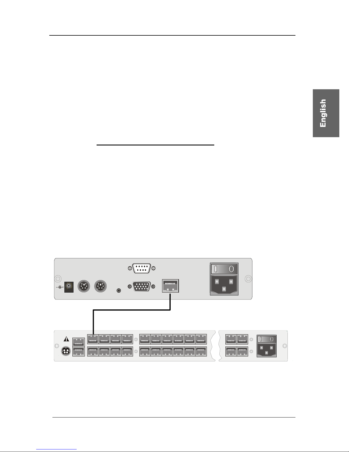
Guntermann & Drunck GmbH CATCenter Installation Guide
• Connecting the keyboard and mouse via USB is possible. To do so,
connect the keyboard and/or mouse to the corresponding interfaces
on the UCON. If you choose straight USB operation then this takes
priority over the PS/2 connection. A mixed connection (e.g. a PS/2
mouse and/or a USB keyboard) is possible.
• If you purchased the optional additional function "TS Function" then
you can connect the LED, which is available for this function to the
LED out interface. You then mount this LED in the vicinity of the
monitor connected to the UCON.
2.2.2 Console Connection via UCON-a
Connect the operator console UCON-a to the CATCenter with a transmission
cable K-C7-x supplied by G&D. The distance between the CATpro2 and the
UCON-a can be up to 100 meters. The maximum distance to the CATCenter is
10 meters.
If other cables are used (e.g. existing CAT5 cable) then the length depends on
the quality of the cable used.
• Insert one end of the transmission cable into the transmission
interface of the UCON-a.
• Insert the other end of the transmission cable into the desired console
interface (RJ45 port) of the CATCenter.
Link
5V DC /5A
Monitor Red. Power
Main Power
A
C 100-240 V, 47-63 Hz
Transmission
Keyb . M ousePS/2 Service
UCON-a
CAT-x-cable
Page 13
CATCenter
12V DC/3A Network A
Network B
56
7
8Console
12
3
4Console
12
3
4
5 6 15 16
17
18 19 20
21 22
31 32
Red.
Power
Main Power
AC 100-240 V, 47-63 Hz
6
7
2
3
Read instruction
carefully before
installing!
Avoid misuse!
KVM Switch.
Page 62

Guntermann & Drunck GmbH CATCenter Installation Guide
Page 14
To connect the local console to the UCON-a, proceed as follows:
• Connect the mouse to the PS/2 mouse port.
• Connect the keyboard to the keyboard port.
• Connect the monitor to the monitor port.
Alternatively, the Acxos system can also be connected to the UCON-a using
the interfaces for the local console. Proceed as follows:
• Connect the 25-pin sub-D plug of the supplied CCP-x cable to the
KVM In interface of the Acxos system.
• Now establish the connection to the keyboard and mouse interfaces of
the UCON-a using the two PS/2 plugs of the CCP-x cable. The two
plugs are marked with the corresponding symbols.
• Connect the 15-pin Sub HD plug of the supplied CCP-x cable to the
monitor interface of the UCON-a.
• The LINK interface is used to connect the serial direct link with the
Acxos system. Connect the sub-D-9 plug to the link interface (sub-D-9
port) of the Acxos and to the LINK interface of the UCON-a.
2.2.3 Connecting the UCON-s
2.2.3.1 Console Connection
Connect the operator console UCON-s to the CATCenter with a transmission
cable K-C7/LD-x supplied by G&D. The distance between the CATpro2 and
the UCON-s can be up to 300 meters. If other cables are used (e.g. existing
CAT5 cable) then the length depends on the quality of the cable used.
• Insert one end of the transmission cable into the transmission
interface of the UCON-s.
• Insert the other end of the transmission cable into the desired console
interface (RJ45 port) of the CATCenter.
Page 63

Guntermann & Drunck GmbH CATCenter Installation Guide
Mouse Keyb.
USB
Keyb. Mouse
PS/2
Main Power
AC 100-240 V, 47-63 Hz
Monitor PC 1 PC 2Service Transmission12V DC/1,2A
Red. Power
UCON-s
CAT-x-cable
Page 15
CATCenter
12V DC/3A Network A
Network B
56
7
8Console
12
3
4Console
12
3
4
5 6 15 16
17
18 19 20
21 22
31 32
Red.
Power
Main Power
AC 100-240 V, 47-63 Hz
6
7
2
3
Read instruction
carefully before
installing!
Avoid misuse!
KVM Switch.
• Plug the keyboard and mouse cables for your workstation into the
corresponding ports on the UCON-s. Connect the monitor to the
monitor interface at the back of the device.
• Connecting the keyboard and mouse via USB is possible. To do so,
connect the keyboard and/or mouse to the corresponding interfaces
on the UCON-s. If you choose straight USB operation then this takes
priority over the PS/2 connection. A mixed connection (e.g. a PS/2
mouse and/or a USB keyboard) is possible.
2.2.3.2 Connecting the Local Targets
To connect the local targets, please proceed as follows:
• Unplug monitor, keyboard, and mouse cables from the targets.
• Monitor:
Insert the 15-pin sub HD plug of the CPU connection dongle CATpro2
into the VGA interface of the target you are connecting.
• Keyboard / Mouse:
Now connect the two PS/2 plugs of the CPU connection dongle
CATpro2 to the keyboard and mouse interfaces of the targets you are
connecting. The two plugs are marked with the corresponding
symbols and are color-coded.
• Now insert one end of the PRO-x (x = length supplied) connection
cable into the RJ45 port of the CATpro2.
• Then connect the other end of the PRO-x (x = length supplied)
connection cable to the desired TARGET interface (RJ45 port) of the
UCON-s.
Page 64

Guntermann & Drunck GmbH CATCenter Installation Guide
2.2.3.3 Switching Between Local Targets and CATCenter
To switch between the local targets connected to the UCON-s or connect to the
CATCenter system you can use the buttons at the front of the UCON-s or
configurable keyboard shortcuts.
a. Using the buttons at UCON-s
Red.
Main
Active
Status
RemotePower
Status
Active
PC 1 PC 2 Trans
The buttons at the front side have the following functions:
PC 1: Connect to the first local target
PC 2: Connect to the second local target
Trans: This button connects to the transmission interface at the back of the
UCON-s (see Chapter 2.2.3.1). Use this button to create a direct
connection to the CATCenter. You then have access to all operating
steps as described in Chapter 2 of the Operating Manual and the
following chapters!
b. Using configurable keyboard shortcuts
Note: The keyboard shortcuts consist of a hotkey and a selectkey. Press both
keys simultaneously, to initiate the shortcut-function.
The key which is to use as hotkey is given by the configuration of CATCenter.
On delivery of the CATCenter the CTRL-key is preset. If you changed the
setting for the hotkey, press the configured key.
The following table shows the keyboard shortcuts to switch between the local
targets and CATCenter:
Hotkey Selectkey Funktion
CTRL + F1 Connect to the first local target
CTRL + F2 Connect to the second local target
CTRL + F3 This button connects to the transmission
interface at the back of the UCON-s (see
Chapter 2.2.3.1).
These keyboard shortcuts can be configured by the user - within the possible
opportunities - in the OSD. Detailed information for this is described in the
following section.
Page 16
Page 65

Guntermann & Drunck GmbH CATCenter Installation Guide
Page 17
Changing the default select-key und executing mouse-utilities
Changes to the default select-key by the user at a UCON are exclusively valid
for the locale UCON because these settings are independent of the CATCenter
system.
Repeat the following steps therefore at each connected UCON-s separately.
Activation und Operation of the OSD
As a prerequisite for activation the OSD, switch to the first or second channel of
UCON-s. Proceed therefore as described above, in order to connect one of
these two channels.
To show the OSD at the monitor of the console, press the defined hotkey
(default: CTRL) and the key NUM. Use arrow keys UPWARD and
DOWNWARD or the mouse wheel to navigate through the menu items.
The functions of the menu items are described in the following sections.
After changing the settings press the key F2 to store the settings.
Selecting a user-defined select-key:
The menu item SELECTKEY offers the possibility to select between the
following possible keys:
Selection Keys
1 - 3 Keys 1, 2, and 3 at the alphanumeric keypad
NUM1 - NUM3 Keys 1, 2 and 3 at the numeric keypad
a-c Keys a, b and c
F1 - F3 Function keys F1, F2, F3
To change the current setting of the UCON-s, mark the menu item SELECT
KEY and press the space bar to change between the different options.
When selecting the keys you should consider that the CATCenter, which can
be also operated by UCON-s, as well supports use of hotkeys (page 40ff. of the
operating instructions) for switching between the different, at the CATCenter
connected, target computers. For this purpose the same kinds of keys are
available, how they are listed above.
Important: The select-keys configured for global use in the CATCenter are not
available when changing the local select key of the UCON-s, in order to avoid
restrictions in the operability of the CATCenter.
Page 66
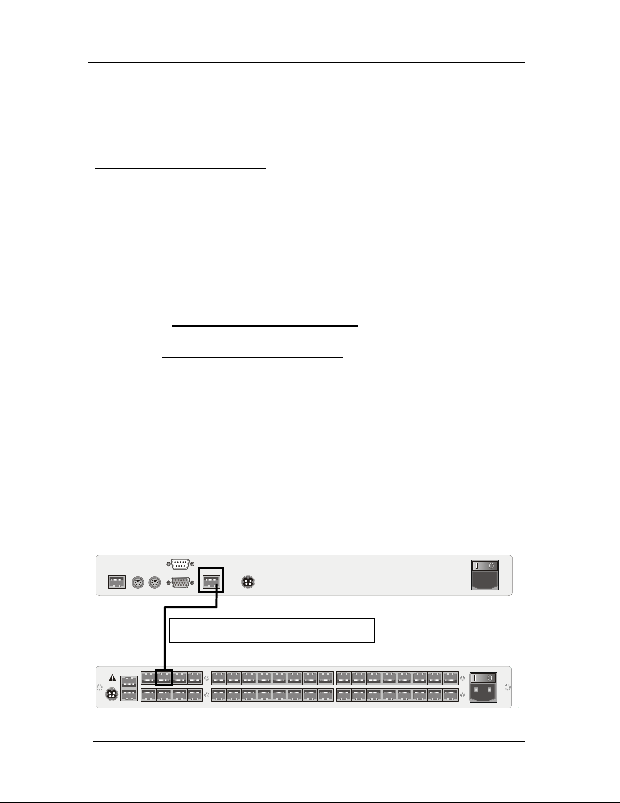
Guntermann & Drunck GmbH CATCenter Installation Guide
In case – for example due to the subsequently change of the select-key of the
CATCenters – UCONs and CATCenter use of the same keys for operating and
configuring the CATCenter and the UCON-s, the select-key of the UCON-s is to
be changed as described above.
Execution of the Mouse utilities:
If the mouse does not function during operation or after maintenance work, use
the Mouse utilities to solve this trouble. The Mouse utilities are available by
selecting menu item MOUSE UTILITIES and pressing the enter key or use of
the left mouse button.
The functions of the Mouse utilities are described in detail on page 30 of the
operating guide.
2.2.4 Connecting the UCON-IP-eco
2.2.4.1 Connecting to the CATCenter
To install the UCON-IP-eco system on a CATCenter, please observe the
following installation steps:
1) Mount the UCON-IP-eco system in a 19" rack
Please ensure that all interfaces of the UCON-IP-eco are easily accessible and
that there is no built-up of heat. The maximum allowable operating temperature
is 40 °C.
2) Connect the UCON-IP-eco system to the CATCenter.
The UCON-IP-eco is connected to an available console port of the CATCenter
with a CAT-x-cable connection cable.
Keyb. MousePS/2
Monitor
12VDC/5AEthernet
COM 1
Red. Power
M
a
i
n
P
o
w
e
r
1
0
0
-
2
4
0
V
/
6
0
-
5
0
H
z
/
0
.
4
-
0
.
2
A
Trans mis si on
Page 18
12V DC/3A Network A
Network B
56 78Console
12
3
4Console
1234
5678CPU910 11 12 13 14 15 16
17 18 19 20 21 22 23 24 CPU 25 26 27 28 29 30 31 32
Red.
Power
Main Power
AC 100-240 V, 47-63 Hz
67
2
3
Read instruction
carefully before
installing!
Avoid misuse!
KVM Switch.
Connection using a CAT-x-cable
Page 67
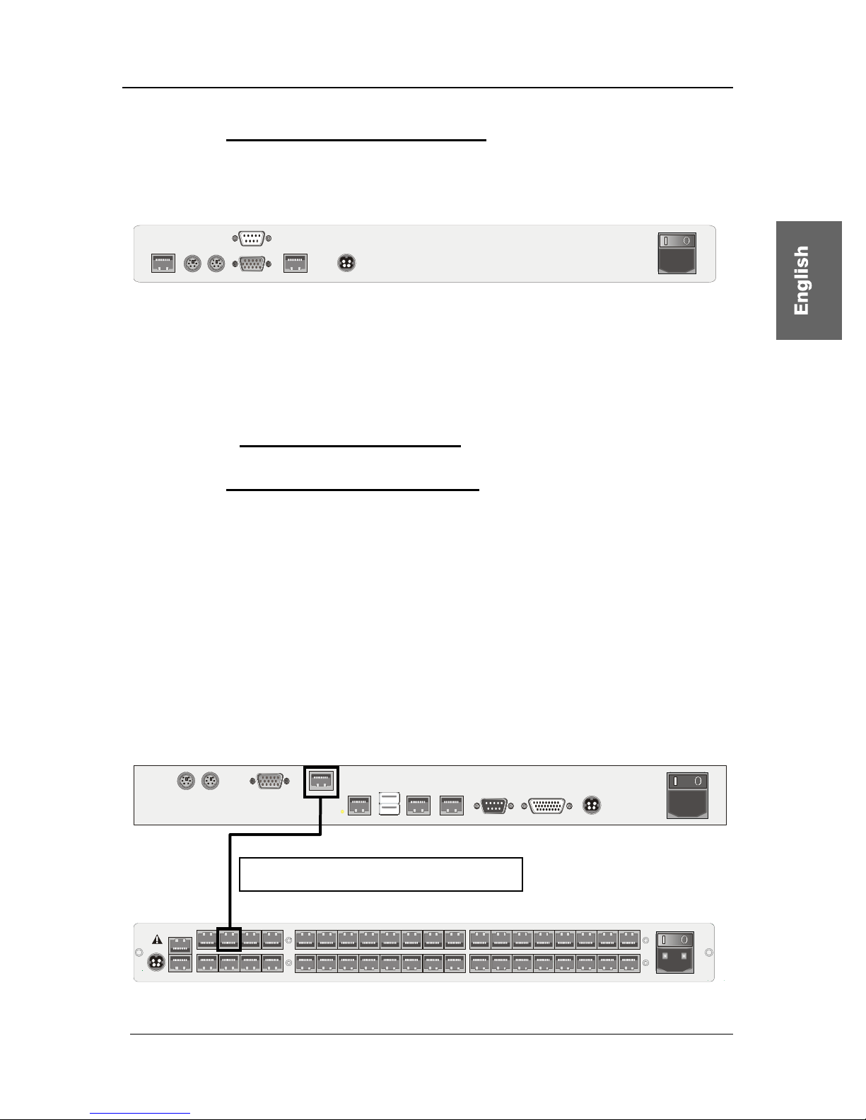
Guntermann & Drunck GmbH CATCenter Installation Guide
2.2.4.2 Connecting the Local Console
To connect the local console to the UCON-IP-eco system, proceed according to
the following installation steps:
Keyb. MousePS/2
Monitor
12VDC/5AEthernet
COM 1
Red. Power
M
a
i
n
P
o
w
e
r
1
0
0
-
2
4
0
V
/
6
0
-
5
0
H
z
/
0
.
4
-
0
.
2
A
Trans mis si on
• Connect the mouse to the PS/2 mouse port.
• Connect the keyboard to the keyboard port.
• Connect the monitor to the monitor port.
2.2.5 Connecting the UCON-IP
2.2.5.1 Connecting to the CATCenter
To install the UCON-IP system on a CATCenter, please observe the following
installation steps:
1) Mount the UCON-IP system in a 19" rack
Please ensure that all interfaces of the UCON-IP are easily accessible and that
there is no built-up of heat. The maximum allowable operating temperature is
45° C.
2) Connect the UCON-IP system to the CATCenter.
The UCON-IP is connected to an available console port of the CATCenter with
the CAT-x-cable.
12V DC/5A
USB
Keyb. Mouse
PS/2
Ethernet A Ethernet B
Service
ISDN
COM 1 Red. Power
Main Power
A
C 100-240 V, 47-63 Hz
TransmissionMonitor
Page 19
12V DC/3A Network A
Network B
56 78Console
12
3
4Console
1234
5678CPU910 11 12 13 14 15 16
17 18 19 20 21 22 23 24 CPU 25 26 27 28 29 30 31 32
Red.
Power
Main Power
AC 100-240 V, 47-63 Hz
67
2
3
Read instruction
carefully before
installing!
Avoid misuse!
KVM Switch.
Connection using a CAT-x-cable
Page 68

Guntermann & Drunck GmbH CATCenter Installation Guide
2.2.5.2 Connecting the Local Console
To connect the local console to the UCON-IP system, proceed according to the
following installation steps:
12V DC/5A
USB
Keyb. Mouse
PS/2
Ethernet A Ethernet B
Service
ISDN
COM 1 Red. Power
Main Power
A
C 100-240 V, 47-63 Hz
TransmissionMonitor
• Connect the mouse to the PS/2 mouse port.
• Connect the keyboard to the keyboard port.
• Connect the monitor to the monitor port.
2.2.5.3 Connecting to an ISDN Device
If you want to access the UCON-IP via ISDN then you have to connect the
UCON-IP to your telephone system.
12V DC/5A
USB
Keyb. Mouse
PS/2
Ethernet A Ethernet B
Service
ISDN
COM 1 Red. Power
Main Power
A
C 100-240 V, 47-63 Hz
TransmissionMonitor
To do so, use a CAT-x-based patch cable. Insert one end (RJ45 plug) into the
ISDN interface of the UCON-IP and the other end (RJ45 plug) into an SO bus
(protocol type EURO-ISDN) of your telephone system.
2.3 Network Interfaces
You can access certain network functionalities indicated in the following using
the network interfaces located at the back of the CATCenter.
• Configure the CATCenter network
• LDAP, Active Directory and RADIUS authentication.
• Time adjustment using an NTP server
• Sending log messages to a Syslog server
• Firmware updates and backups
The CATCenter Xview software is used for the tasks listed above. This software
is described in a separate manual!
Page 20
Page 69

Guntermann & Drunck GmbH CATCenter Installation Guide
Page 21
2.4 Power Supply
Connect the supplied power cables to the Main POWER ports of the devices
(CATCenter, UCON, UCON-a, UCON-s, and UCON-IP).
A redundant power supply can be optionally connected to the Red. Power port.
To do so, use the optionally available power supply component PowerSetX/TypeX (type depends on the device ordered).
2.5 Installing the Expansion Unit
The number of targets that can be connected can be increased to 512 (1024,
2048) by cascading. This number of targets is reached within 2 cascade levels.
128 targets can be connected within the first cascade level. The maximum
number of 512 targets is reached in the second cascade level.
The CATCenter devices must be connected to each other for cascading. You
can use a common CAT cable to create a connection between two CATCenter
units. We recommend the following for this purpose:
• PRO-X cable for lengths up to 20 meters
• K-C7-LD-x cable for lengths over 20 meters
Make sure that the total distance between the CATpro2 and UCON-a does not
exceed 100 meters, or 300 meters for the UCON and UCON-s.
The remainder of this installation description pertains to a CAT cable
.
The master device has a total of 32 CPU ports available for cascading.
Assuming that 8 consoles are connected to the master device and all of them
are to access all targets, then one CPU port has to be used for cascading every
console connection. Therefore, 8 CPU ports have to be used on the master
device so that all 8 consoles can continue to access all connected targets.
If, on the other hand, you only have one console then you only have to use one
CPU port on the master; this is identical to the method described above.
In general, the following applies: For every console access
implemented on the slave, the same number of CPU ports must be
available on the master!
Page 70

Guntermann & Drunck GmbH CATCenter Installation Guide
Corresponding to this system at the back of the CATCenter, the 32 CPU ports
of the master device can be divided into the following segments for cascading
(this setting is intended as a recommendation):
• CPU Ports 1 – 8 Enables connection of a first slave device within
the first cascade level
• CPU Ports 9 – 16 Enables connection of a second slave device
within the first cascade level
• CPU Ports 17 – 24 Enables connection of a third slave device within
the first cascade level
• CPU Ports 25 – 32 Enables connection of a fourth slave device
within the first cascade level
Note:
The CPU assignment within a CPU port range is used to provide a clear
overview during and after cascading. However, you can connect a slave
device to any desired CPU port of the master device.
The following illustration clarifies how the first slave device is connected to the
master device within the first cascade level:
Master device
5
678Console
12 3 4Console 1 2 3 4 5 6 7 8CPU9 10111213141516
17 18
19
20
21 22
23
24 CPU
25 26
27
28
29 30
31
32 Main Po wer
A
C 100-240 V, 47-6 3 Hz
5V DC/5A Network A
Network B
Read instruction
carefully before
installing!
Avoid misuse!
KVM Switch.
Red.
Power
56 78Console
1
234Console 1 2 3 4 5 6 7 8CPU9 10111213141516
17 18 19 20 21 22 23 24 C PU 25 26 27 28 29 30 31 32
Main Po wer
AC 100-240 V, 47- 63 Hz
5V DC/5A Network A
Network B
Read instruc tion
carefully before
installing!
Avoid misuse!
KVM Switch.
Red.
Power
1111 1111
4444 4444
22
2
22222
3333 3333
Slave device of the
first cascade level
The CPU ports 1 – 8 are connected to the slave device with one CAT cable
each (that is, with a total of 8 CAT cables). These CAT cables are attached to
the RJ45 console connection ports on the slave device.
If you would like to connect a second slave device to the master device, use the
CPU ports 9 - 16 and connect these ports to the console ports of the second
slave device.
Follow the same procedure to connect the third and fourth slave device.
Page 22
Page 71

Guntermann & Drunck GmbH CATCenter Installation Guide
When the maximum number of four slave devices is connected to the master
device, then no targets can be connected directly to the master.
If you wish to connect more than 128 targets then you need to use the second
cascade level. To do so, additional CATCenter units have to be connected.
However, these are not connected to the master device but to the CATCenter
units of the first cascade level. The procedure used to connect these
CATCenter units is exactly the same as described above.
Master device
5
678Console
1234Console 1 2 3 4 5 6 7 8 CPU 9 10 11 12 13 14 15 16
17 18
19
20
21 22
23
24 CPU
25 26
27
28
29 30
31
32 Main Power
A
C 100-240 V, 47-63 Hz
5V DC/5A Network A
Network B
Read instruction
carefully before
install ing!
Avoid misuse!
KVM Switch.
Red.
Power
5
678Consol e
1
234Consol e 1 2
3
4
5678CPU
9101112
13 14
15
16
17 18 19 20 21 22 23 24 CPU 25 26 27 28 29 30 31 32
Main Power
A
C 100-240 V, 47-63 Hz
5V DC/5A Network A
Network B
Read instruction
carefully before
installing!
Avoid misuse!
KVM Switch.
Red.
Power
56 78Console
1
234Console 1234567 8CPU910111213141516
17 18 19 20 21 22 23 24 CPU 25 26 27 28 29 30 3 1 32
Main Power
AC 100-240 V, 47-63 Hz
5V DC/5A Network A
Network B
Read instruction
carefully before
installing!
Avoid misuse!
KVM Switch.
Red.
Power
1111 1111
4444 4444
22
2
22222
3333 3333
Slave device of the
first cascade level
Slave device of the
second cascade level
To connect the targets to the slave devices, follow the procedure described in
Chapter 2.1.
All CATCenter products can be combined using the procedures described
above. Thus, you can combine:
• CATCenterX8 master with CATCenterX4 slave
• CATCenterX8 master with CATCenterX2 slave
• CATCenterX4 master with CATCenterX4 slave
• CATCenterX4 master with CATCenterX2 slave
• CATCenterX2 master with CATCenterX2 slave
For all of these combinations you always have to keep in mind that, for the
desired number of consoles (e.g. a maximum of 2 consoles for a CATCenterX2
slave), the same corresponding number of CPU ports have to be reserved on
the master (thus 2 CPU ports on the CATCenter master for a CATCenterX2
slave with two consoles).
Page 23
Page 72

Guntermann & Drunck GmbH CATCenter Installation Guide
Page 24
2.6 Installing HardBoot CCX
Please see the "Hardboot_CCX" manual for a description of the HardBoot
CCX installation.
Page 73

Guntermann & Drunck GmbH CATCenter Installation Guide
Page 25
3 Network Connection – Initial IP Configuration
You can establish the network settings for your CATCenter X8 in the
NETWORK submenu to make the CATCenter accessible via the network.
To do so, log on using the administrator login name and password. This
password can be found in Chapter 6.
Then press the F11 key in the SELECT menu that opens. The
CONFIGURATION menu opens. In the CONFIGURATION menu, use the UP
ARROW and/or DOWN ARROW keys on your keyboard or your mouse to
select the entry Network and then press the ENTER key. A submenu opens
allowing you to establish the following settings:
Network Management
Global
Network A
Network B
ESC
You can establish the following settings in this menu:
• The gateway used to access the CATCenter X8.
• The IP addresses and Network A & Network B (found at the back of
the CATCenter X8).
In addition, you can use do this settings with the toolware "CATCenter Xview"
included in the scope of delivery (see the CATCenter Xview Manual).
Press the ESC key to exit this menu.
Page 74

Guntermann & Drunck GmbH CATCenter Installation Guide
Page 26
3.1.1 Defining the Gateway
The standard gateway must be defined so that the CATCenter X8 can be
reached from all parts of more complex networks.
To do so, use the UP ARROW and/or DOWN ARROW keys on your keyboard
or the mouse to select the entry GATEWAY in the NETWORK MANAGEMENT
submenu and then press ENTER. The following window opens:
Edit Network Global
Gateway 192.XXX.XXX.XXX
ESC F2: Save
Now enter the IP address of the gateway on the gateway row. To do so, use
either the right arrow / left arrow keys or the TAB key to move to one of the
four fields. Press the ENTER key to activate edit mode in each individual field;
the font color changes to yellow.
All editing tasks carried out up to this point are saved by pressing F2.
Press ESC to exit the menu without saving the changes you have made. If you
choose to do this, a warning message is displayed.
Warning
You did not save your changes!
Press
F2 to save and exit
ENTER to exit without saving
ESC to cancel
F2 : Save and exit
Enter : Exit without saving
ESC: Cancel
Press the F2 key to permanently save your changes. You then return to the
NETWORK MANAGEMENT submenu.
Page 75

Guntermann & Drunck GmbH CATCenter Installation Guide
3.1.2 Defining the Network Parameters for Network A and/or B
As a final network configuration step, unique settings (e.g. assignment of an IP
address) have to be established for at least one of the network interfaces
located at the back of the CATCenter X8 so that the CATCenter X8 can be
reached.
The back of the CATCenter X8 has two network interfaces.
12V DC/3A Network A
Network B
56 78Console
12
3
4Console
1234
5678CPU910 11 12 13 14 15 16
17 18 19 20 21 22 23 24 CPU 25 26 27 28 29 30 31 32
Red.
Power
Main Power
AC 100-240 V, 47-63 Hz
67
2
3
Read instruction
carefully before
installing!
Avoid misuse!
KVM Switch.
Please note that the settings under "Network A" only affect the physical
interface "Network A" on the CATCenter X8.
Since the settings for Network A and Network B are identical, these settings
are explained below using Network A only.
To establish these settings, use the UP ARROW and/or DOWN ARROW keys
on your keyboard or the mouse to select the entry INTERFACE A in the
NETWORK MANAGEMENT submenu and then press ENTER. The following
window opens:
Edit Network A
MAC address 00:0F:F4:00:00:18
Assignment static
Address 192.XXX.XXX.XXX
Netmask 255. 255. 255.0
Connection A u t o
ESC F2: Save
The second line of the header displays the MAC address of the network
interface Network A. It cannot be edited.
Use the field Assignment to determine whether the CATCenter X8 receives:
• a static IP address (static)
• a dynamic IP address (DHCP)
• no IP address (off)
Page 27
Page 76

Guntermann & Drunck GmbH CATCenter Installation Guide
Page 28
Use the Spacebar (toggle) to switch between the 3 entries:
• Static
• DHCP
• Off
The two following entries are only available if you select the definition Static.
Note:
In the delivery state the IP-adress has the value 192.168.0.10.
Use the field Address to assign the static IP address of the CATCenter X8. To
do so, use the right arrow / left arrow keys or the TAB key to move to one of
the four fields. Press the ENTER key to activate edit mode in each individual
field; the font color changes to yellow.
Enter the network mask in the Netmask field. To do so, use either the right
arrow / left arrow keys or the TAB key to move to one of the four fields. The
default is 255.255.255.0. Press the ENTER key to activate edit mode in each
individual field; the font color changes to yellow.
Establish the Ethernet connection speed and mode in the Connection field.
The following selections are available:
• Manually establishing the Ethernet connection speed and mode
(100MBit full-duplex, 100MBit half-duplex, 10MBit full-duplex,
10MBit half-duplex)
• Allowing the network interface and its communication partner (second
computer, hub, switch to negotiate the speed (Auto; default setting)
Note:
The communication behavior can be negatively influenced by the use of various
network components. Thus the setting "Auto" does not always achieve
satisfactory results, depending on the manufacturer.
All editing tasks carried out up to this point are saved by pressing F2.
Press ESC to exit the menu without saving the changes you have made. If you
choose to do this, a warning message is displayed.
Page 77

Guntermann & Drunck GmbH CATCenter Installation Guide
Page 29
Warning
You did not save your changes!
Press
F2 to save and exit
ENTER to exit without saving
ESC to cancel
F2 : Save and exit
Enter : Exit without saving
ESC: Cancel
Press the F2 key to permanently save your changes. You then return to the
NETWORK MANAGEMENT submenu.
Page 78

Guntermann & Drunck GmbH CATCenter Installation Guide
4 LED Indicators
4.1 CATCenter
4.1.1 Front
After connecting the power supply cable, turn the CATCenter on using the
toggle switch at the back of the device. The LEDs on the front of the
CATCenter have the following meaning:
enter
Main
Status
RS232
Service
Power
Red.
Switch
Net
CATCenter
POWER Redundant Illuminated if a redundant power supply is connected and is
supplying 12V.
Main Illuminated if the main power supply is connected and supplying
power.
Status Ready Flashes at irregular intervals if the network subsystem is
running.
Is not illuminated if no network functionality is supported.
Switch Flashes rapidly when the CATCenter system is operating.
4.1.2 Back
LEDs for every RJ45 interface are located at the back of the device.
These LEDs have the following meaning:
2 3 4 5 6 7 8 Server 9 10 11 12 13 14 15 16243Consol e11
56 7 8Console
17
18 19 20 21 22 23 24 25 26 27 28 29 30 31 32Server
Read instruction
carefully before
installing!
Avoid misuse!
KVM Switch.
Network A
Network B
12V DC/3A
Red.
Power
Console LEDs CPU LEDs Network LEDs
Yellow Port is currently in use
by a user.
Port is currently in use
by a user.
Illuminated constantly
for a full-duplex
connection; flashes for
a half-duplex
connection (collision).
Green A connection exists to
a UCON-device.
A connection exists so
a CATpro2.
Indicates the
connection status.
Flashes during activity.
Page 30
Page 79

Guntermann & Drunck GmbH CATCenter Installation Guide
4.2 UCON
4.2.1 Front
After connecting the power cable, turn on the UCON using the toggle switch at
the back of the device. The LEDs on the front of the UCON have the following
meaning:
Red.
Main
Active
Status
RemotePower
UCON
POWER Redundant Illuminated if a redundant power supply is connected and is
supplying 12V.
Main Illuminated if the main power supply is connected and supplying
power.
Remote Active Illuminated when a keyboard has been initialized.
Flashes when no keyboard has been initialized.
Status Always illuminated.
4.2.2 Back
Mouse Keyb.
100-240V/60-50Hz
0.2-0.1A
USB
Keyb. MousePS/2 Monitor
LED out
Tra ns mi ssi onService
12VDC/800mA
Red. Power
There are LEDs for the RJ45 interface at the back of the device.
These LEDs have the following meaning:
CPU LEDs
Yellow Port is currently in use by a user
Green Connection has been established to the CATCenter.
Page 31
Page 80

Guntermann & Drunck GmbH CATCenter Installation Guide
4.3 UCON-s
4.3.1 Front
After connecting the power cable, turn on the UCON-s using the toggle switch
at the back of the device. The LEDs on the front of the UCON-s have the
following meaning:
Red.
Main
Active
Status
RemotePower
Status
Active
PC 1 PC 2 Trans
UCON-s
PC1 Active Illuminated when TARGET1 is active.
Status Illuminated when TARGET1 is running.
PC2 Active Illuminated when TARGET2 is active.
Status Illuminated when TARGET2 is running.
Trans Active Illuminated when the CATCenter is being accessed.
Status Illuminated when the CATCenter is running.
Power Red. Illuminated if a redundant power supply is connected and is
supplying 12V.
Main Illuminated if the main power supply is connected and
supplying power.
Remote Active Illuminated when a keyboard has been initialized.
Flashes when no keyboard has been initialized.
Status Always illuminated when the CATCenter is operational.
4.3.2 Back
LEDs for every RJ45 interface are located at the back of the device.
These LEDs have the following meaning:
Mouse Keyb.
USB
Keyb. M ouse
PS/2
Main Power
A
C 100-240 V, 47-63 Hz
Monitor PC 1 PC 2Service Tra nsmi ssi on12V DC/1,2A
Red. Power
Transmission LEDs CPU LEDs
Yellow Port is currently in use by a user Port is currently in use by a user
Green Connection has been established
to the CATCenter.
Connection has been established to the
local CPU via the CATpro2.
Page 32
Page 81

Guntermann & Drunck GmbH CATCenter Installation Guide
4.4 UCON-a
4.4.1 Front
After connecting the power cable, turn on the UCON-a using the toggle switch
at the back of the device. The LEDs on the front of the UCON-a have the
following meaning:
Red.
Main
Active
Status
RemotePower
UCON-a
POWER Redundant Illuminated if a redundant power supply is connected and is
supplying 5V.
Main Illuminated if the main power supply is connected and supplying
power.
Remote Active Illuminated when a keyboard has been initialized.
Flashes when no keyboard has been initialized.
Status Always illuminated when the CATCenter is operational.
4.4.2 Back
There are LEDs for the RJ45 interface at the back of the device.
These LEDs have the following meaning:
Link
Keyb. M ousePS/2
5V DC/5A
Monitor Red. Power
Main Power
A
C 100-240 V, 47-63 Hz
Service Transmission
CPU LEDs
Yellow Port is currently in use by a user
Green Connection has been established to the CATCenter.
Page 33
Page 82

Guntermann & Drunck GmbH CATCenter Installation Guide
4.5 UCON-IP-eco
4.5.1 Front
After connecting the power cable, turn on the UCON-IP-eco using the toggle
switch at the back of the device. The LEDs on the front of the UCON-IP-eco
have the following meaning:
Red.
Main
Active
Status
SystemPower
UCON-IP-eco
POWER Redundant Illuminated if a redundant power supply is connected and is
supplying 12V.
Main Illuminated if the main power supply is connected and supplying
power.
Remote Active Illuminated when a session has been initiated on the UCON-IP.
Status Always illuminated when the CATCenter is operational.
4.5.2 Back
There are LEDs for transmission and Ethernet RJ45 interfaces at the back of
the device. These LEDs have the following meaning:
Keyb. MousePS/2
Monitor
12VDC/5AEthernet
COM 1
Red. Power
M
a
i
n
P
o
w
e
r
1
0
0
-
2
4
0
V
/
6
0
-
5
0
H
z
/
0
.
4
-
0
.
2
A
Trans mis si on
Transmission LEDs
Yellow Port is currently in use by a user
Green Connection has been established to the CATCenter.
Ethernet LEDs
Yellow Illuminated constantly for a full-duplex connection; flashes for a half-duplex
connection (collision)
Green Indicates the connection status. Flashes during activity.
Page 34
Page 83

Guntermann & Drunck GmbH CATCenter Installation Guide
4.6 UCON-IP
4.6.1 Front
After connecting the power cable, turn on the UCON-IP using the toggle switch
at the back of the device. The LEDs on the front of the UCON-IP have the
following meaning:
Red.
Main
Active
Status
SystemPower
UCON-IP
POWER Redundant Illuminated if a redundant power supply is connected and is
supplying 12V.
Main Illuminated if the main power supply is connected and supplying
power.
Remote Active Illuminated when a session has been initiated on the UCON-IP.
Status Always illuminated when the CATCenter is operational.
4.6.2 Back
There are LEDs for transmission and Ethernet RJ45 interfaces at the back of
the device. These LEDs have the following meaning:
12V DC/5A
USB
Keyb. Mouse
PS/2
Ethernet A Ethernet B
Service
ISDN
COM 1 Red. Power
Main Power
A
C 100-240 V, 47-63 Hz
TransmissionMonitor
Transmission LEDs
Yellow Port is currently in use by a user
Green Connection has been established to the CATCenter.
Ethernet LEDs
Yellow Illuminated constantly for a full-duplex connection; flashes for a half-duplex
connection (collision)
Green Indicates the connection status. Flashes during activity.
Page 35
Page 84

Guntermann & Drunck GmbH CATCenter Installation Guide
Page 36
4.7 CATpro2 Series
The meanings of the flashing CATpro2 LEDs are as follows:
CATpro2
LED flashes 3 times per
second
No connection to the CATCenter
LED flashes briefly every
1.5 seconds
Connection has been established to the CATCenter but
the target is not active
LED illuminated Connection has been established to the CATCenter and
the target is active
LED flashes irregularly Connection has been established to the CATCenter, the
target is active, and keyboard / mouse data are being
transmitted
Page 85

Guntermann & Drunck GmbH CATCenter Installation Guide
Page 37
5 Technical specifications
5.1 CATCenter X2
Workstation ports per device
2
Workstation ports max. per cluster
16
Transmission type to workstation module
dedicated CAT-x link
Target ports
16
Target ports Cascade level 1
128
Target ports Cascade level 2
1024
Transmission type to target module
dedicated CAT-x link
Update process
local service socket
Network connection
no
Power supply
Main Type internal power pack
Connection IEC connector (IEC-320 C14)
Voltage
AC100-240V/60-50Hz 130 - 80 mA
Redundant Type external power pack
(optional) Connection miniDIN-4 power socket
Voltage +12VDC/1A
Casing
Material anodised aluminium
Dimensions
Desktop 435 x 44 x 286 mm (W x H x D)
Rackmount
19” x 1HU x 286 mm (W x H x D)
Weight approx. 2.5 kg
Operating
Temperature +5 to +45 °C
environment
Air humidity < 80%, not-condensing
Interfaces
to workstation module RJ45 socket
to target module RJ45 socket
for update 2.5 mm jack
for power switch RJ11 socket
Conformity
CE, RoHs
Page 86

Guntermann & Drunck GmbH CATCenter Installation Guide
Page 38
5.2 CATCenter X4
Workstation ports per device
4
Workstation ports max. per cluster
32
Transmission type to workstation module
dedicated CAT-x link
Target ports
32
Target ports Cascade level 1
256
Target ports Cascade level 2
2048
Transmission type to target module
dedicated CAT-x link
Update process
local service socket
Network connection
no
Power supply
Main Type internal power pack
Connection IEC connector (IEC-320 C14)
Voltage
AC100-240V/60-50Hz 180 - 110 mA
Redundant Type external power pack
(optional) Connection miniDIN-4 Power-Buchse
Voltage +12VDC/2,3A
Casing
Material anodised aluminium
Dimensions
Desktop 435 x 44 x 286 mm (W x H x D)
Rackmount
19” x 1HU x 286 mm (W x H x D)
Weight approx. 3.0 kg
Operating
Temperature +5 to +45 °C
environment
Air humidity < 80%, not-condensing
Interfaces
to workstation module RJ45 socket
to target module RJ45 socket
for update 2.5 mm jack
for power switch RJ11 socket
Conformity
CE, RoHs
Page 87

Guntermann & Drunck GmbH CATCenter Installation Guide
Page 39
5.3 CATCenter X8
Workstation ports per device
8
Workstation ports max. per cluster
64
Transmission type to workstation module
dedicated CAT-x link
Target ports
32
Target ports Cascade level 1
128
Target ports Cascade level 2
512
Transmission type to target module
dedicated CAT-x link
Update process
via network
Network connection
yes
Power supply
Main Type internal power pack
Connection IEC connector (IEC-320 C14)
Voltage
AC100-240V/60-50Hz 280 - 150 mA
Redundant Type external power pack
(optional) Connection miniDIN-4 Power-Buchse
Voltage +12VDC/2,9A
Casing
Material anodised aluminium
Dimensions
Desktop 435 x 44 x 286 mm (W x H x D)
Rackmount
19” x 1HU x 286 mm (W x H x D)
Weight approx. 3.0 kg
Operating
Temperature +5 to +45 °C
environment
Air humidity < 80%, not-condensing
Interfaces
to workstation module RJ45 socket
to target module RJ45 socket
for network RJ45 socket
for update via network port
for power switch RJ45 socket
Conformity
CE, RoHs
Page 88

Guntermann & Drunck GmbH CATCenter Installation Guide
Page 40
5.4 UCON-a
Signal type/video
analogue video
Video resolution
(depending on cable)
locale connection 1920 x 1440 @ 75 Hz
Transmission length
Workstation module to target module
100 m
Transmission type to workstation module
dedicated CAT-x link
Workstations
1
Delay compensation
no
Update process
local service socket
Assigned workstation connections at
central module
1
Additional connectable
Workstation computer
0
Power supply
Main Type internal power jack
Connection IEC connector (IEC-320 C14)
Voltage
AC100-240V/60-50Hz 130 - 70 mA
Redundant Type external power pack
(optional) Connection 2 pole hollow socket
Voltage +5VDC/1,3A
Casing
Material anodised aluminium
Dimensions
Desktop 210 x 44 x 211 mm (W x H x D)
Rackmount
19” x 1HU x 211 mm (W x H x D)
Weight approx. 1.1 kg
Operating
Temperature +5 to +45 °C
environment
Air humidity < 80%, not-condensing
Interfaces
for workstation SubHD15 socket (Vdeo)
2 x PS/2 socket (Keyboard/Mouse)
to central module RJ45 socket
for update 2,5 mm jack
Conformity
CE, RoHs
Page 89

Guntermann & Drunck GmbH CATCenter Installation Guide
Page 41
5.5 UCON
Signal type/video
analogue video
Video resolution
(depending on cable)
locale connection 1920 x 1440 @ 75 Hz
Transmission length
Workstation module to target module
300 m
Transmission type to workstation module
dedicated CAT-x link
Workstations
1
Delay compensation
yes
Update process
local service socket
Assigned workstation connections at
central module
1
Additional connectable
Workstation computer
0
Power supply
Main Type internal power jack
Connection IEC connector (IEC-320 C14)
Voltage
AC100-240V/60-50Hz 0.2 - 0.1A
Redundant Type external power pack
(optional) Connection miniDIN-4 power socket
Voltage +12VDC/0,8A
Casing
Material anodised aluminium
Dimensions
Desktop 270 x 44 x 211 mm (W x H x D)
Rackmount
19” x 1HU x 211 mm (W x H x D)
Weight approx. 1.3 kg
Operating
Temperature +5 to +45 °C
environment
Air humidity < 80%, not-condensing
Interfaces
for workstation SubHD15 socket (Video)
2 x PS/2 socket (Keyboard/Mouse)
2 x USB-A socket (Keyboard/Mouse)
SubD9-socket (TradeSwitch-LED)
to central module RJ45 socket
for update 2,5 mm jack
Conformity
CE, RoHs
Page 90

Guntermann & Drunck GmbH CATCenter Installation Guide
Page 42
5.6 UCON-s
Signal type/video
analogue video
Video resolution
(depending on cable)
locale connection 1920 x 1440 @ 75 Hz
Transmission length
Workstation module to target module
300 m
Transmission type to workstation module
dedicated CAT-x link
Workstations
1
Delay compensation
yes
Update process
local service socket
Assigned workstation connections at
central module
1
Additional connectable
Workstation computer
2
Power supply
Main Type internal power jack
Connection IEC connector (IEC-320 C14)
Voltage
AC100-240V/60-50Hz 0.2 - 0.1A
Redundant Type external power pack
(optional) Connection miniDIN-4 power socket
Voltage +12VDC/0,8A
Casing
Material anodised aluminium
Dimensions
Desktop 270 x 44 x 211 mm (W x H x D)
Rackmount
19” x 1HU x 211 mm (W x H x D)
Weight approx. 1.3 kg
Operating
Temperature +5 to +45 °C
environment
Air humidity < 80%, not-condensing
Interfaces
for workstation SubHD15 socket (Video)
2 x PS/2 socket (Keyboard/Mouse)
2 x USB-A socket (Keyboard/Mouse)
for local workstations computers
2 x RJ45 socket
to central module RJ45 socket
for update 2,5 mm jack
Conformity
CE, RoHs
Page 91

Guntermann & Drunck GmbH CATCenter Installation Guide
Page 43
5.7 UCON-IP-eco
Signal type/video
analogue video
Video resolution
locale connection 1920 x 1440 @ 75 Hz
(depending on cable)
via IP native 1280 x 1024 @ 75 Hz
Transmission length
Workstation module to target module
300 m
Transmission type to workstation module
dedicated CAT-x link
Transmission type to KVM-IP client
TCP/IP protocol
Communication
Ethernet 10/100 Mbit/s
Workstations
2 (1 x IP; 1 x local; concurrent)
Delay compensation
yes
Update process
via network
Assigned workstation connections at
central module
1
Power supply
Main Type internal power jack
Connection IEC connector (IEC-320 C14)
Voltage
AC100-240V/60-50Hz 0.3 - 0.2A
Redundant Type external power pack
(optional) Connection miniDIN-4 power socket
Voltage +12VDC/1,1A
Casing
Material anodised aluminium
Dimensions
Desktop 435 x 44 x 356 mm (W x H x D)
Rackmount
19” x 1HU x 356 mm (W x H x D)
Weight approx. 3.0 kg
Operating
Temperature +5 to +45 °C
environment
Air humidity < 80%, not-condensing
Interfaces
for workstation SubHD15 socket (Video)
2 x PS/2 socket (Keyboard/Mouse)
to central module RJ45 socket
for network RJ45 socket
for ISDN -
for update via network port
Conformity
CE, RoHs
Page 92

Guntermann & Drunck GmbH CATCenter Installation Guide
Page 44
5.8 UCON-IP
Signal type/video
analogue video
Video resolution
locale connection 1920 x 1440 @ 75 Hz
(depending on cable)
via IP native 1280 x 1024 @ 75 Hz
Transmission length
Workstation module to target module
300 m
Transmission type to workstation module
dedicated CAT-x link
Transmission type to KVM-IP client
TCP/IP protocol
Communication
Ethernet 10/100 Mbit/s or ISDN
Workstations
2 (1 x IP; 1 x local; concurrent)
Delay compensation
no
Update process
via network
Assigned workstation connections at
central module
1
Power supply
Main Type internal power jack
Connection IEC connector (IEC-320 C14)
Voltage
AC100-240V/60-50Hz 0.5- 0.3A
Redundant Type external power pack
(optional) Connection miniDIN-4 power socket
Voltage +12VDC/2.3A
Casing
Material anodised aluminium
Dimensions
Desktop 435 x 44 x 211 mm (W x H x D)
Rackmount
19” x 1HU x 211 mm (W x H x D)
Weight approx. 3.5 kg
Operating
Temperature +5 to +40 °C
environment
Air humidity < 80%, not-condensing
Interfaces
for workstation SubHD15 socket (Video)
2 x PS/2 socket (Keyboard/Mouse)
to central module RJ45 socket
for network 2 x RJ45 socket
for ISDN RJ11 socket
for update via network port
Conformity
CE, RoHs
Page 93

Guntermann & Drunck GmbH CATCenter Installation Guide
Page 45
5.9 CATpro2 Standard
Signal type/video
analogue video
No. of interfaces to central module
1
Total length incl. cable
0.3 m
Transmission rate (RS232)
-
Power supply
Main Type via keyboard-interface of target
Connection
PS/2 resp. USB
Voltage
+5VDC
Casing
Material Plastic
Dimensions
45 x 20.7 x 65 mm (W x H x D)
Design Converter
Weight approx. 120 g
Operating
Temperature +5 to +45 °C
environment
Air humidity < 80%, not-condensing
Interfaces
CATpro2-PS/2
2 x PS/2, 1 x SubHD15 plug
to target
CATpro2-USB
1 x USB-A, 1 x SubHD15 plug
CATpro2-SUN-USB (de)
1 x USB-A, 1 x SubHD15- plug
CATpro2-SUN-USB (us)
1 x USB-A, 1 x SubHD15 plug
Interfaces
to central module
RJ45 jack
Conformity
CE, RoHs
Page 94

Guntermann & Drunck GmbH CATCenter Installation Guide
Page 46
5.10 CATpro2-VT100
Signal type/video
serial, VT100
No. of interfaces to central module
1
Total length incl. cable
2.0 m
Transmission rate (RS232)
max. 115200 bps
Power supply
Main Type external power supply
Connection
miniDIN-4 power socket
Voltage
+12VDC
Casing
Material anodised aluminium
Dimensions
105 x 26 x84 mm (W x H x D)
Design Converter
Weight approx. 200 g
Operating
Temperature +5 to +45 °C
environment
Air humidity < 80%, not-condensing
Interfaces
to target
SubD9 socket
Interfaces
to central module
RJ45 jack
Conformity
CE, RoHs
Page 95

Guntermann & Drunck GmbH CATCenter Installation Guide
Page 47
6 Index
AdonIS................................................................................................................................7
Assignment.......................................................................................................................27
Cascading ....................................................................................................................7, 22
CATCenter .........................................................................................................................7
CATpro2 .............................................................................................................................7
CAT-x Cable.......................................................................................................................7
CONFIGURATION Menu .................................................................................................25
Connection .......................................................................................................................28
Console ..............................................................................................................................7
Console Connection .........................................................................................................12
Console Port.......................................................................................................................8
CPU Port ............................................................................................................................8
Expansion Unit .................................................................................................................21
Gateway ...........................................................................................................................26
HardBoot CCX..................................................................................................................24
Initial IP Configuration ......................................................................................................25
Network ..............................................................................................................................8
Network Connection .........................................................................................................25
Network Interfaces ...........................................................................................................20
Network Parameters.........................................................................................................27
Power Supply ...................................................................................................................21
Service Port........................................................................................................................8
Switching...........................................................................................................................16
Target .................................................................................................................................8
Target Connection..............................................................................................................9
Technical specifications ...................................................................................................37
Transmission ......................................................................................................................8
UCON...........................................................................................................................8, 12
UCON-a............................................................................................................................13
UCON-IP ..........................................................................................................................19
UCON-IP-eco ...................................................................................................................18
UCON-s............................................................................................................................14
Page 96

Guntermann & Drunck GmbH CATCenter Installation Guide
Page 48
List of Test Standards
This device conforms to the legal provisions of the EU guideline 89/336/EEC for
Electromagnetic Compatibility, modified by RL 91/236/EEC and 92/31/EEC
of the council.
Test basis:
EN 55022 Kl.B + A1, A2 (1998) Emission
EN 55024 + A1, A2 (1998) Stability
EN 61000-3-2 (2000) Harmonics
EN 61000-3-3 + A1 (1998) Flicker
And:
The 73/23/EEC guideline regarding Electrical Equipment for use within certain
voltage limits, modified by RL 93/68/EEC of the council.
Test basis:
EN 60950-1 (2003) Safety – Information Technology
Address:
Guntermann & Drunck GmbH
Dortmunder Str. 4a
D-57234 Wilnsdorf, Germany
E-mail: sales@gdsys.de
Website: http://www.gdsys.de
Page 97

NOTES
Page 98

NOTES
Page 99

NOTES
Page 100

Das Handbuch wird fortlaufend aktualisiert und im Internet veröffentlicht.
http://gdsys.de/A9100030
The manual is constantly updated and available on our website.
Guntermann & Drunck GmbH
Obere Leimbach 9
57074 Siegen
Germany
http://www.gdsys.de
sales@gdsys.de
 Loading...