

Page 1

GCC Networking Guide
Contents
Introduction to networking your printer ................................................1
Why should I set up a network? ..............................................................1
What does setting up a network involve? ..............................................2
Where do I connect the printer? .............................................................2
What happens when someone turns a computer off?...........................3
What if more than one person wants to print at the same time? ........ 3
What about security? ............................................................................... 3
Which kind of network layout – bus or star?..........................................4
How will I know if I have enough printers for everyone? .....................4
NEST – Introduction ..................................................................................5
Setting up your printer.............................................................................5
General NetWare setup ............................................................................ 5
NetWare 3.12 instructions ........................................................................6
PCONSOLE ...................................................................................... 6
Creating a Print Queue .................................................................. 6
Creating a Print Server...................................................................7
NetWare 4.1 instructions .......................................................................... 9
Setting up PCONSOLE ....................................................................9
Creating a User.............................................................................11
Creating a User with NWADMIN.................................................11
G
CC
TECHNOLOGIES
Page 2

Creating a User with NETADMIN ........................................................... 12
Using GCC tools to remotely configure NEST on your printer ............. 14
Using WebAdmin to set up NEST........................................................... 14
NetWare 3.12 setup with WebAdmin.................................................... 14
NetWare 4.x setup with WebAdmin ...................................................... 15
Using the NEST Config Tool to set up NEST .......................................... 16
To sort the list of devices ............................................................. 17
To filter the list of devices ........................................................... 17
To filter the list ............................................................................. 17
Editing a device ........................................................................... 18
Understanding the Device Configuration dialog box .......................... 18
Displaying an item and its description ....................................... 18
Editing an item............................................................................. 18
Restoring the default values of an item, subject, or device ..... 18
Changing the password for a device .......................................... 19
Completing your editing ............................................................. 19
Configuring Windows computers that use your NEST printer............. 19
Control-d and PostScript printing ............................................... 19
Preventing a Windows 3.1 computer from sending Control-d 19
Preventing a Windows 95 computer from sending Control-d . 19
Special NEST considerations ................................................................... 20
Problems you may encounter ................................................................ 20
Config Page NEST info ................................................................. 20
Typical problems with solutions ................................................. 20
WebAdmin – Introduction...................................................................... 23
Page 3

Getting started........................................................................................23
Connecting to WebAdmin...................................................................... 24
Navigating WebAdmin ........................................................................... 24
Linking to pages...........................................................................24
Refreshing information ...............................................................26
Printer Status frame ..................................................................... 26
Changing the printer’s configuration .........................................26
Printing Informational pages ...................................................... 27
WebAdmin Security ................................................................................ 28
WebAdmin password...................................................................28
TCP/IP address restriction.............................................................30
WebAdmin index .................................................................................... 31
WebAdmin messages..............................................................................31
Setting up TCP/IP protocol ..................................................................... 33
Troubleshooting tips...............................................................................34
TCP/IP – Introduction ..............................................................................35
Software overview ..................................................................................35
Installing the optional filters ................................................................. 36
Setting up the printer on a TCP/IP network .......................................... 36
Placing the printer .................................................................................. 36
Configuring the control panel TCP/IP parameters ................................ 36
TCP/IP submenu descriptions..................................................................38
Identifying the printer to the network .................................................39
Confirming the network connection ..................................................... 40
Introduction to printing over a TCP/IP network ...................................40
Page 4

Print jobs can be sent to a printer in two ways: ...................................40
Print with the internal lpd ..................................................................... 41
Creating a spool directory ......................................................................41
Configuring the internal spooler ........................................................... 41
Attaching a hard disk to the printer .....................................................42
Sending print jobs to the internal spooler ............................................42
Printing with a master (Berkeley) spooler with tcpif ........................... 43
Creating a spool directory on the master spooler ................................ 43
Editing the printcap files ........................................................................ 43
Printing text files with texttcpif.............................................................44
Using tcpof ..............................................................................................45
Using telnet with the printer ................................................................. 45
TCP/IP Notes - A: TCP/IP overview ..........................................................46
TCP/IP Notes - B: TCP/IP addressing ........................................................ 47
IP address .....................................................................................47
IP address class ............................................................................. 48
IP address restrictions ..................................................................48
IP subnet masks ............................................................................48
Broadcast address ........................................................................49
TCP/IP Notes - C: TCP/IP Restrictions.......................................................50
Ethernet – Introduction .......................................................................... 52
Ethernet network connection ...............................................................52
10Base-T (Unshielded Twisted-Pair or UTP) network connection .......52
10Base-2 (RG-58, Thin Coax, or Thinnet) network connection ............ 52
Direct Ethernet connection .................................................................... 54
Page 5

Direct Ethernet connection options ......................................................54
Option 1 - Apple Attachment Unit Interface (AAUI) .................54
To connect the printer to a computer using an AAUI port ....... 54
Option 2 - BNC to BNC connection .............................................55
To connect the printer to a computer with a BNC connector ... 55
Configuring the printer for network operation ................................... 56
Configuring EtherTalk software on your computer .............................57
Configuring your Macintosh for Ethernet communication .................58
Configuring EtherTalk software on a PC-compatible ...........................58
Network activity LED ..............................................................................58
Page 6

Introduction to networking your printer
Note: The following information is a guide. It covers the broad outline of
networking, and is not intended to give you all the information you need to
set up a network. Consult the documentation that came with your computer
and operating system. If you have doubts about whether you are able to
install a network yourself, we recommend that you consult a professional in
the field.
You can use your GCC printer on networks. This section of the manual gives you a brief
overview of the process and the costs and benefits. Because networks vary considerably
from one site to another, the information in this section is a general guide only.
There are two kinds of networks; peer to peer, where every computer can communicate
with any other, and client-server, where one or more computers are dedicated as servers
and all the other computers on the network are clients.
Client-server computing is normally complicated and is usually administered by trained
network specialists. This is because most client-server software can control up to thousands
of users, and many features are provided that are not needed at smaller sites.
This section deals mainly with peer to peer networks as these are easier to set up and
administer. Depending on the amount of printing that your organization produces, one
printer can support up to 25 users. You can always add additional printers as necessary.
Why should I set up a network?
You can set up a network and reap benefits with only two computers. Benefits include:
• One printer will service both users; therefore you save the cost of another printer.
• Depending on how the network is configured, one user can allow the other access to
some, all, or none of the files on the computer, and this access can be read-only or
read and write. You save on the inconvenience of transferring files by “SneakerNet”
— carrying floppy disks from one computer to the other.
• Other peripherals can be shared. You can copy files or install programs from a CDROM drive on another computer. You save the cost of equipping both computers
with a full range of peripherals.
• Some networks let you mix Macs and PCs so that both platforms can share the
printer.
• Most networks have e-mail. Even in small offices e-mail makes sure that messages get
to the person who needs them, rather than being lost in a sea of paper.
1
Page 7

• Depending on your software, you may have additional benefits like the ability to use
one computer to send and receive faxes for every user on the network, or being able to
back up files to a central disk or tape drive.
What does setting up a network involve?
You need to install a network card in each computer, and provide cable to connect the
computers together. In a bus network, each computer is connected to the next in a line; in a
star network, all computers are connected to a device called a hub. The reasons why you
would choose a bus or a star network are discussed later.
The cost per computer (the cost of a network card and cabling) starts at under $100. You
pay more for ease of installation of the card and for faster networking, though the speed of
standard Ethernet is more than adequate for small sites. Hubs start at under $100, and the
more expensive models allow you to connect more computers (basic hubs often have only
five ports).
Most Macintosh computers have some form of networking built-in. All models have
AppleTalk, and more recent models have EtherTalk, Apple’s name for its Ethernet implementation. You can mix AppleTalk and EtherTalk computers on the same network.
AppleTalk’s disadvantage is that it is considerably slower than Ethernet. You could find
that users on an AppleTalk network become tired of waiting. You can upgrade many Macs
to Ethernet.
Where do I connect the printer?
In most cases, you connect the printer directly to a computer on the network. When other
users want to print, the file is sent to the computer with the printer attached and stored
temporarily on that computer’s hard drive. Then the file is printed in the background. This
means that someone working on the computer attached to the printer can continue working on their own programs while the computer is sending the file to the printer.
Some Macintosh networks allow you to connect the printer directly to the network cable,
rather than connecting it to a printer.
If many people are sending large files to the printer the person using the computer attached
to the printer may find the computer is slowing down; in most cases this will not be a
problem. Some organizations dedicate an older computer to be a print server. This computer is not normally used for any other purpose; it must be able to run the operating
system of the other computers and have sufficient free hard drive space to hold the files
that are being printed.
2
Page 8

If you decide to use a computer as a print server, you may consider also using it as a fax
server if your software allows you to do this. Fax servers take the place of a fax machine;
they are left on continuously, and users have a password-protected area to receive faxes.
Fax servers can also send faxes from anyone on the network, and the printer takes the place
of the printing part of a fax machine. A fax server needs a modem and a phone line.
What happens when someone turns a computer off?
The network continues to run if a computer is turned off, but the files, printer, and other
resources associated with that computer are no longer available to other computers on the
network.
What if more than one person wants to print at the same time?
When several people send files to the computer attached to the printer, the first file received is printed, and the remainder are queued — that is, they are stored in order on the
hard drive and printed in order when the printer is free.
What about security?
Once a computer is connected on a network you must do more than lock the door to
prevent access to it. Most systems allow you to specify which folders or directories can be
shared with other users, and let you name the users and specify that they have the correct
password. Computers that print sensitive materials should not print to printers in a public
area.
Passwords aren’t usually the first thing on peoples’ minds when a small network is set up,
but without proper password protection many unwanted things can happen. These can
include malicious e-mail sent under your name, employee snooping of sensitive material,
and outsiders sneaking into an office to search the network while the user is out to lunch.
People tend to choose passwords that are easy to remember; unfortunately, these passwords are also easy to deduce. Names of spouses, children or pets may be known to coworkers. If passwords are too complex people tend to write them down and put them in a
desk drawer, which defeats the purpose.
MHALLIFW is an example of a password that cannot be easily guessed, but it seems that
could be easily forgotten until you realize that it is the initial letters of the first eight words
of the nursery rhyme “Mary had a little lamb.” Initial letters of lines from songs or advertising slogans can also be used.
3
Page 9

Which kind of network layout — bus or star?
When you make network using a bus layout, you use a type of cable called thin Ethernet.
This cable and the connectors used with it are called 10BASE-2. You do not need a hub for
a bus network, but if the cable is broken at any point some computers will not be able to
communicate with the others.
In contrast, a problem with a cable on a star network means that only one computer is
affected. The cabling used is called Unshielded Twisted Pair (UTP), and this method is
called 10BASE-T. For a simple network, either method will be satisfactory.
In some cases, if your computer comes with a network card, you may be forced to use one
system or the other unless you replace the card. Other network cards may have both
interfaces.
How will I know if I have enough printers for everyone?
If you do not have enough printers for your needs, your users will tell you. They will
complain about having to wait until their jobs appear. In this case, you can add a printer to
the network.
4
Page 10

NEST : Introduction
NEST (Novell Embedded Software Technology) is code written by Novell and licensed by
GCC. It provides NetWare protocols and is configured using standard NetWare utilities. It
offers these advantages:
• Your printer does not require a dedicated print server, so it connects directly to the
network.
• You can install the printer anywhere you have an Ethernet connection.
• NEST works with GCC’s WebAdmin utility.
This manual shows you how to install and configure your GCC printer to work with your
NetWare network. You set up your printer in two steps – the usual NetWare setup, followed by the GCC specific NEST setup. If any of the computers on your network are
creating PostScript jobs using Windows, you will also need to configure them.
The printer’s NEST specific parameters are set up using GCC’s WebAdmin utility. Instructions for accessing and using the WebAdmin utility are located later in this section and in
Section 2 of this manual.
If you do not have TCP/IP on your network, you will be unable to use WebAdmin. In that
case you will need to use GCC’s NEST Config Tool, which is supplied on this CD.
Setting up your Printer
The instructions in this section are a condensed version of those in the installation guide, and
are intended for users experienced in setting up network laser printers. If you have questions
about any of the steps in this section, consult that section of the manual.
1. Unpack the printer and install the toner cartridge.
2. Insert paper into the paper tray and insert the paper tray into the printer.
3. Connect a cable from the Ethernet port to the network.
4. Plug the AC power cord into the printer, then plug it into a grounded AC
outlet.
5. Switch on the printer.
General NetWare Setup
This section discusses the NetWare utilities you use to set up your printer. This process is
the same as setting up any printer, but in a few cases there are specific instructions to
configure the NEST options. These are included in the instructions where necessary.
5
Page 11

The instructions are described first for NetWare 3.12, and then for NetWare 4.1 (beginning
on page 1-6). The utilities included in this section are PCONSOLE, NWADMIN, and
NETADMIN.
NetWare 3.12 instructions
PCONSOLE
PCONSOLE has two functions: setting up and managing print queues, and setting up and
managing print servers. This manual covers the outline of how to set up queues and servers; you must create at least one queue and one print server. For more details consult your
NetWare documentation.
Creating a Print Queue
1. Log into the file server as SUPERVISOR (or equivalent).
2. Start the PCONSOLE program (it is located in SYS:PUBLIC).
First you create a print queue.
3. From the menu (shown in figure 1) choose Print Queue Information.
4. Press Ins to add a new item to the list of queues.
5. Type the name of the new queue and press Enter.
Then you add users to the queue.
6. With your new queue selected, press Enter again.
7. Choose Queue Users from the Print Queue Information menu and
press Enter.
8. Modify the list of users as necessary.
9. Press Esc to return to the Print Queue Information menu.
Choose queue operators (people or groups that can manage this queue).
10. Choose Queue Operators from this menu and press Enter.
11. Modify the list of users and groups as necessary.
12. Press Esc three times to return to the PCONSOLE main menu.
13. Repeat steps 3-12 to create further queues as needed, then proceed to
the next section.
6
Page 12
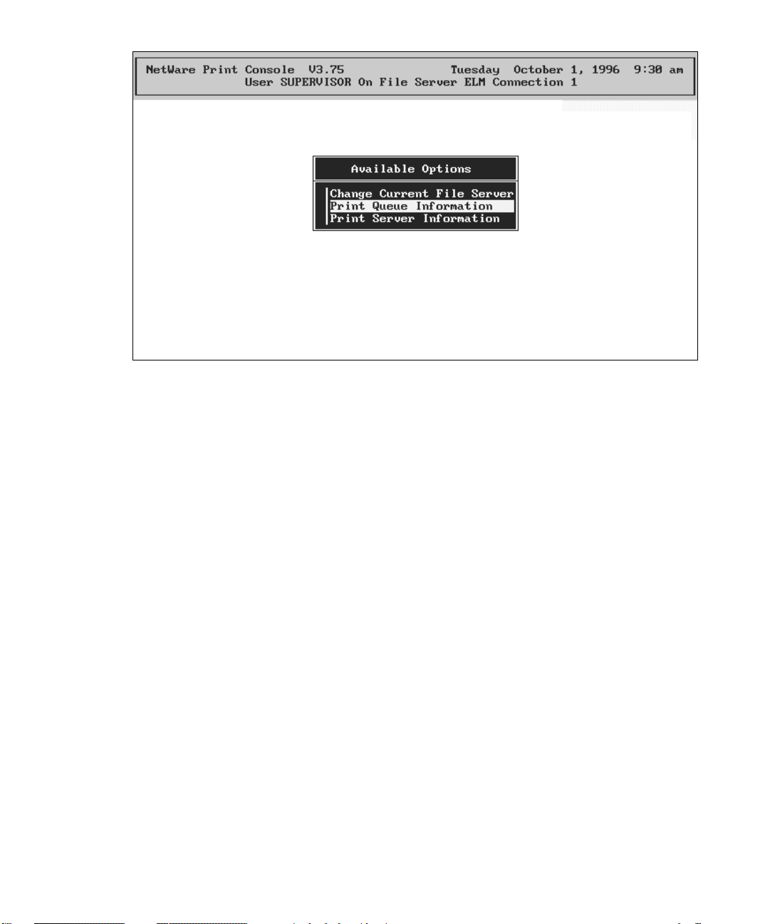
Figure 1. PCONSOLE’s opening menu.
Creating a Print Server
1. Choose Print Server Information.
First you create a new server.
2. Press Ins to add a new item to the list of servers.
3. Type the name of the new server and press Enter. Make a note of the
name of this server; you will need this when you use GCC’s WebAdmin,
which is described later in this section.
Then you assign users to this server.
4. With your new server selected, press Enter again.
5. Choose Print Server Users from the Print Server Information menu and
press Enter.
6. Modify the list of users as necessary.
7. Press Esc to return to the Print Server Information menu.
Then you choose users who can manage the print server.
8. Choose Print Server Operators from this menu and press Enter.
9. Modify the list of operators as necessary.
10. Press Esc to return to the Print Server Information menu.
7
Page 13
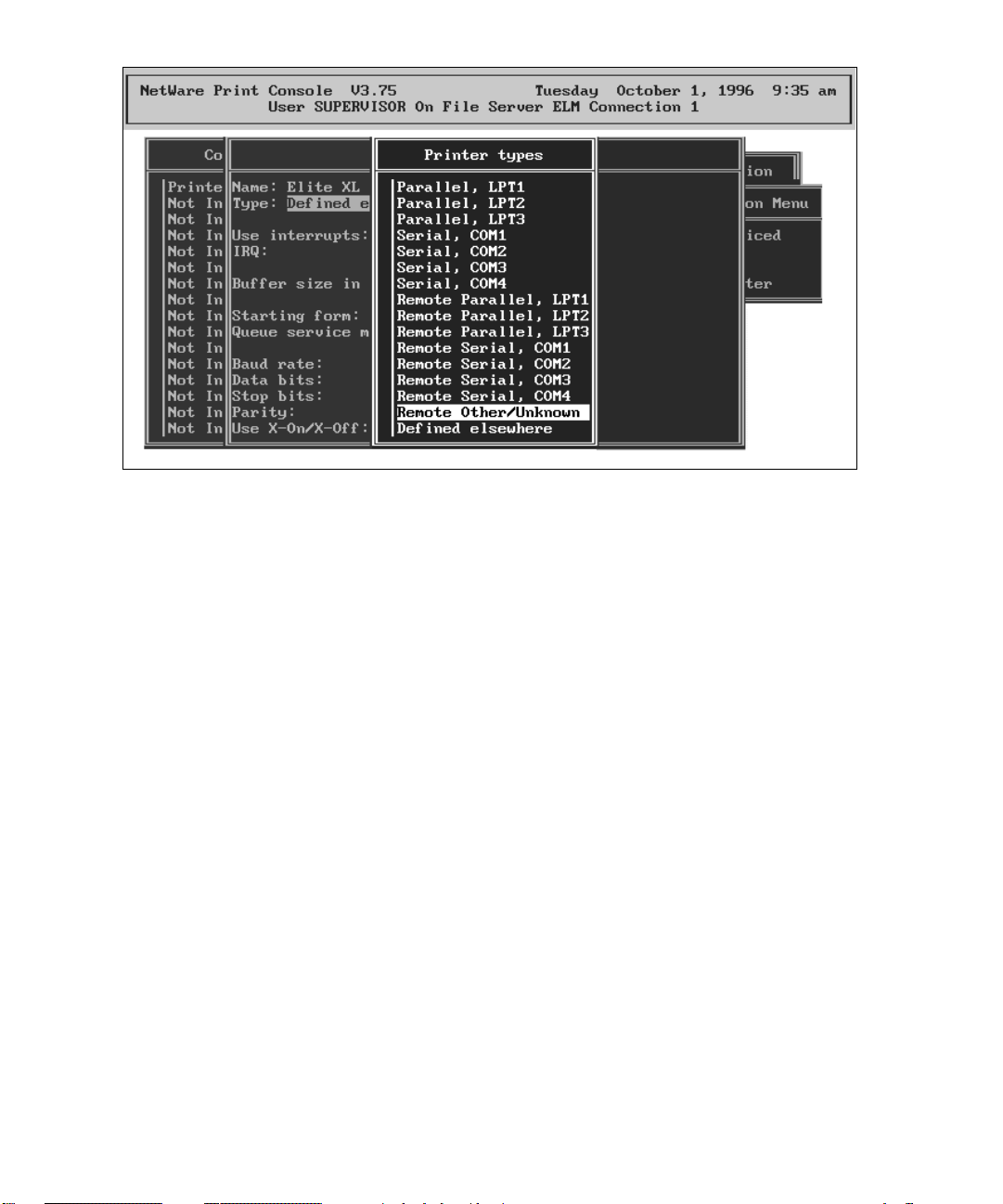
Figure 2. Selecting “Remote Other/Unknown” from the list of Printer types.
Now you configure the printer.
11. Choose Print Server Configuration from this menu and press Enter.
12. Choose Printer Configuration from this menu and press Enter.
13. You must configure the printer as printer zero (0). Press Enter.
14. Type a name for the printer and press Enter.
15. You will see a list of Printer Types (as in figure 2). Your printer must be
defined as Other Remote/Unknown. Select this option from the list.
Finally you assign your queue to your printer.
16. When you have defined your printer, press Esc to return to the Print
Server Configuration menu.
17. Choose Queues Serviced by Printer from this menu and press Enter.
18. Assign the queue you just created to the printer (see your NetWare documentation for more details).
19. When you have finished, press Esc to return to the Print Server Con-
figuration menu.
You may want to implement this optional item.
20a. Choose Notify List for Printer and press enter.
8
Page 14

20b. Choose the printer, and then select users that you wish to be notified
when the printer has a problem (see your NetWare documentation for
more details).
20c. When you have completed your Notify List, press Esc until you return to
the Print Server Information menu.
When you have made all your changes, you exit PCONSOLE.
21. Press Esc three times to return to the PCONSOLE main menu.
22. Press Esc to save changes and exit PCONSOLE.
This ends the section of this manual devoted to NetWare 3.12. Now continue with the
section “NEST-specific Setup” on page 11.
NetWare 4.1 instructions
Setting up PCONSOLE
1. Log into the network as SUPERVISOR (or equivalent).
2. Start the PCONSOLE program (it is located in SYS:PUBLIC).
3. Change to the correct context, and make a note of it. (You will need this
when you use GCC’s WebAdmin utility, discussed in a later section.)
4. Choose Quick Setup and press Enter (see figure 3).
5. Enter the Print Server Name. Press Enter, then press Insert and type the
name. Make a note of this name; you will need it when you use GCC’s
WebAdmin utility, discussed in a later section.
6. Change the New Printer and the New Print Queue entries in the same
way.
7. Choose the volume where you will store your print queues.
8. Change the Banner Type to PostScript or Text as appropriate.
9. Choose the Printer Type. For your GCC printer this must be Other/Un-
known.
10. Press Esc several times to return to the PCONSOLE main menu.
11. Press Esc to save changes and exit PCONSOLE.
9
Page 15
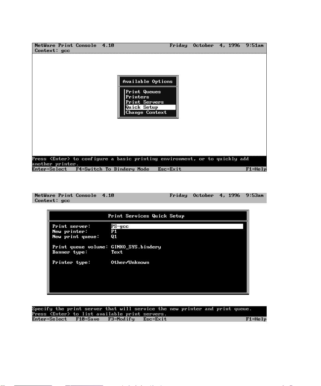
Figure 3. Choosing Quick Setup from PCONSOLE’s opening screen.
Figure 4. PCONSOLE’s Quick Setup screen.
10
Page 16
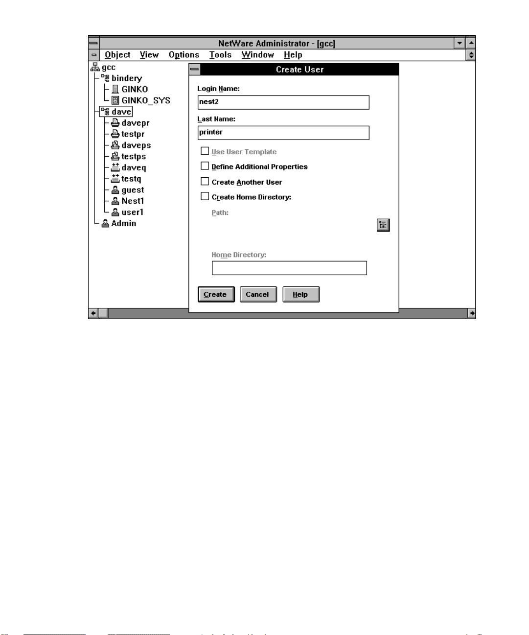
Figure 5. Creating a user in NWADMIN
Creating a User
NPRINTER must log in to the network, so you are required to create a user for this purpose. You can do this either by using the NWADMIN utility (Windows) or the
NETADMIN utility (DOS).
Creating a User with NWADMIN
1. Log into the network as SUPERVISOR (or equivalent).
2. Start the NWADMIN program (it is located in SYS:PUBLIC).
3. Change the context, if necessary, to the same as the printer. Choose
Change Context and press Insert to browse the list of available contexts.
Choose the correct context and press F10.
4. Highlight your required context.
5. Press Insert and choose a user object from the list, then press Enter.
6. Type the login name and press Tab.
7. Type the last name and press Enter.
11
Page 17
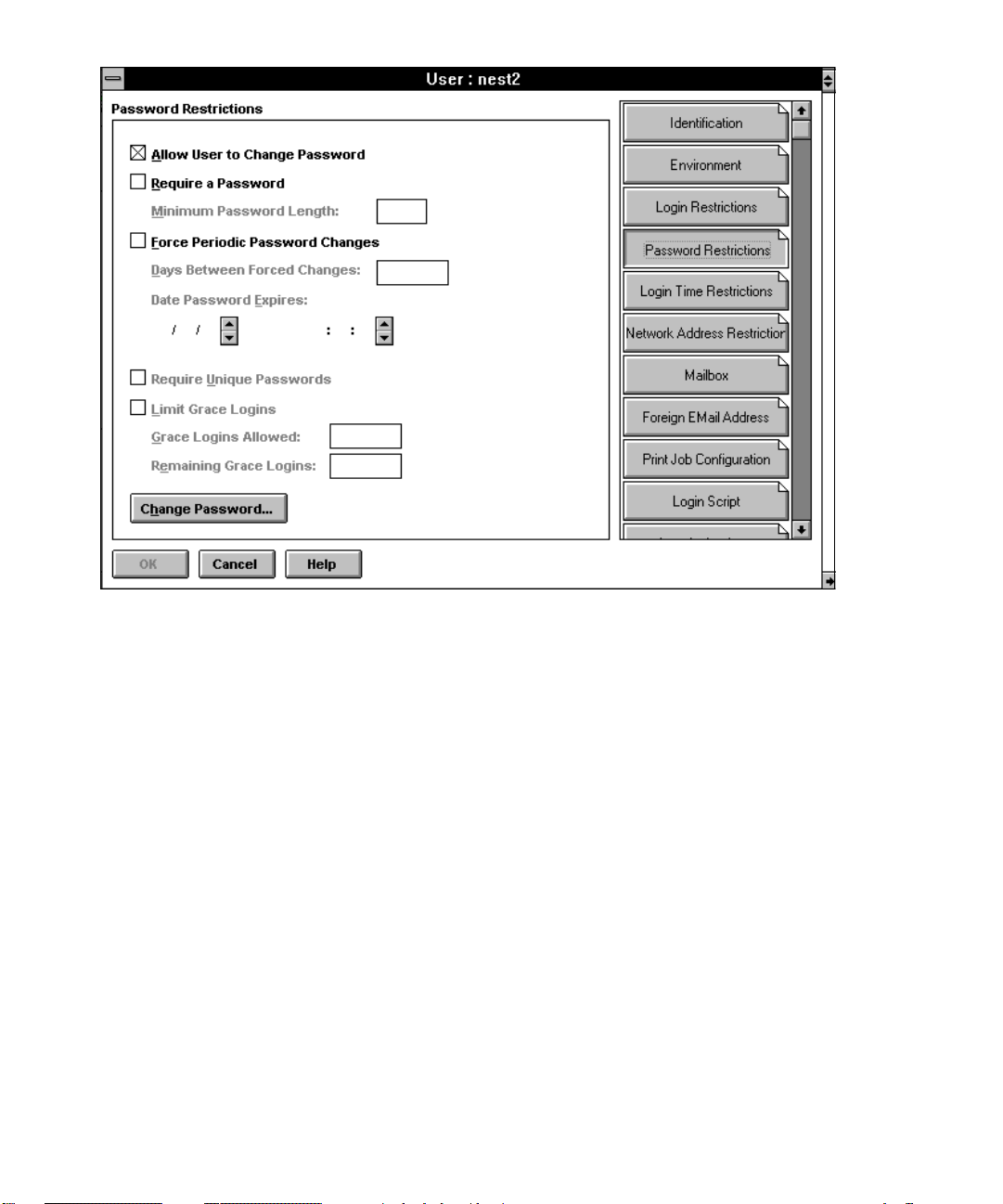
Figure 6. The Password screen in NWADMIN.
8. Click on the Create button.
9. Double-click on the user name to display the User dialog box.
Now you set a password.
10. Click on the Password Restriction button.
11. Click on the Change Password button.
12. Type the new password and press Enter, then type the password again
to verify it.
13. Make a note of the user name and password; you will need them for the
GCC WebAdmin setup.
14. Click on the OK button to exit this dialog box. Your user is created.
Creating a User with NETADMIN
1. Log into the network as SUPERVISOR (or equivalent).
2. Start the NETADMIN program (it is located in SYS:PUBLIC).
12
Page 18
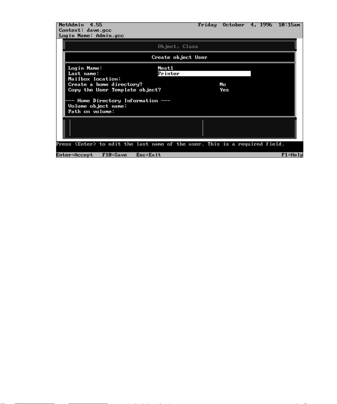
Figure 7. Creating a user in NETADMIN
3. Change the context, if necessary, to the same as the printer. Choose
Change Context and press Insert to browse the list of available contexts.
Choose the correct context and press F10.
4. Choose Manage Objects from the NETADMIN options list and press
Enter.
5. Press Insert to add an object.
6. Choose User and press Enter.
7. Type the login name and press the down arrow key.
8. Type the last name and press Esc.
Now you change properties or set a password, if necessary.
9. If you do not want to change properties or passwords, go to step 14.
10. Press Enter to see the Actions List.
11. View or edit properties of the User object.
12. Press Enter. If you need to change or create a password, choose Change
Password and press Enter, otherwise go to step 14.
13. Type the password and press Enter. Type the password again to verify
it and press Enter.
14. Press Esc four times to exit NETADMIN and save your changes.
13
Page 19

Using GCC tools to remotely configure NEST on your printer
GCC provides two tools to let you remotely configure NEST.
If your network uses TCP/IP, WebAdmin allows you to view and/or change many parameters of the printer using a World Wide Web browser over an Ethernet network. Please see
the WebAdmin section of this manual for information on installation and setup of the
WebAdmin utility.
If your network doesn’t use TCP/IP, you can use the NEST Config tool to view and configure NEST printers.
Using WebAdmin to set up NEST
The following instructions for setting up NEST with a GCC printer apply to both NetWare
3.12 and 4.X.
All GCC printers on the network that you are intending to use with NEST MUST be
accessible using WebAdmin. The following instructions assume you have followed the
setup in Section 2 and are able to access the printer using WebAdmin.
First, ensure that NEST is enabled on the printer.
1. Launch your World Wide Web browser and attached to your printer as
explained in Section 2.
2. Select (click) NETWORKS from the WebAdmin main menu. The Networks
main menu is displayed.
3. If NEST is disabled, use the pull-down menu to enable it and restart your
printer.
4. Once the printer is configured with NEST enabled, select the NEST link.
The NEST Subjects menu appears.
The NEST Subjects menu displays the available subject items (General, Network,
NPRINTER and PSERVER) that may be changed. If you select one of the links on this
page, a menu of parameters will be displayed for the subject you have selected.
The following information pertains only to those items that are required to change for
NEST printing. If you are installing under NetWare 3.12, continue with the instructions
below. If you are installing under NetWare 4.x, skip to the section that deals with this
version of NetWare.
NetWare 3.12 setup with WebAdmin
If you are installing under NetWare 3.12, you will need to configure the following items.
14
Page 20

1. From the WebAdmin Networks menu, select the Network link. From the
Network configuration menu:
a) Change the FRAMETYPE item to a frametype that is supported by your file server.
b) Change the MODE item to Bindery.
c) Change the PREFERRED SERVER item to the name of your file server.
2. From the WebAdmin Networks menu, select the PSERVER link. From the
PSERVER configuration menu:
a) Change the PRINT SERVER NAME item to the print server name that you created
earlier in this chapter when you used PCONSOLE to configure your file server.
b) Change the PASSWORD item to the password you set (if you set one) for the print
server when using PCONSOLE.
3. Click the box that is labeled Restart printer automatically and press
the submit new settings button. The printer will save your changes and
reboot.
NetWare 4.x setup with WebAdmin
If you are installing under NetWare 4.x, you will need to configure the following items.
1. From the WebAdmin Networks menu, select the Network link. From the
Network configuration menu:
a) Change the FRAMETYPE item to a frametype that is supported by your file server.
b) Change the MODE item to Directory Services.
c) Change the PREFERRED SERVER item to the name of your file server.
d) Change the PREFERRED DS TREE item to the name of your directory services tree.
e) Change the DS Name Context item to the context that contains the print server
object, printer object and user that you created earlier in this section.
2. From the WebAdmin Networks menu, select the NPRINTER link. From
the NPRINTER configuration menu:
a) Change the USER NAME item to the common name of the user object that you
created earlier in this section.
b) Change the USER PASSWORD item to the password you set (if you set one) for the
user.
15
Page 21

Figure 8. The NEST Configuration tool
3. From the WebAdmin Networks menu, select the PSERVER link. From the
PSERVER configuration menu:
a) Change the PRINT SERVER NAME item to the print server name that you created
earlier in this chapter when you used PCONSOLE to configure your file server.
b) Change the PASSWORD item to the password you set (if you set one) for the print
server when using PCONSOLE.
4. Click the box that is labeled Restart printer automatically and press
the submit new settings button. The printer will save your changes and
reboot.
Using the NEST Config Tool to set up NEST
GCC’s NEST Config Tool allows you to configure NEST devices on your network if you do
not have TCP/IP. When you start the Config tool, it polls the network and returns a list of
NEST-enabled devices.
To install the GCC Nest Config tool, follow the instructions in the readme file located in
the NESTTOOL directory on the CD-ROM.
If you have a small number of devices on your network, they may all be visible in the
Config tool main screen, or you may be able to quickly scroll to a particular device. If this
is the case, proceed to the section following, called “Editing the Device.” However, if you
have a large number of devices you may first need to use the Sort and Filter features.
16
Page 22

Figure 9. The Device Configuration dialog box. Depending on the item you are
configuring, there may be slight differences in the Item Value section.
To sort the list of devices
You can sort the devices in ascending order using the Sort command on the menu bar.
1. Click on the Sort menu on the menu bar.
2. Choose the parameter you wish to sort by. The list of devices is sorted.
To filter the list of devices
You can filter the list to show only certain devices. The resulting list can be filtered again if
necessary.
You use the filter drop-down boxes to limit the number of devices shown in the list. These
lists default to an asterisk, to show that all items are selected for that parameter. The dropdown lists display all unique values for the parameter.
Alternatively, you can enter a parameter value in the box or use the wildcard characters
asterisk (*) or question mark (?). An asterisk represents any number of characters, whereas
each question mark represents a single character.
To filter the list:
1. Select a value from one or more of the drop-down list boxes, or type in a
parameter value in the box.
17
Page 23

2. Click on the Rediscover button to the right of the drop-down lists. The list
is filtered.
If you wish to show all items for a particular parameter, choose the asterisk from the dropdown list.
Editing a device
When you can see the device that you require, you can proceed to edit. Only one device
can be edited at a time.
1. Either click once on the device name and click on the Select button, or
double-click on the device name.
2. A password dialog box appears. The default name is admin and the password is also admin. (You can change the password in the Device Configuration dialog box). Enter your name and password, and click OK.
3. If your password allows you to edit this device, the Device Configura-
tion dialog box appears (see figure 9).
Understanding the Device Configuration dialog box
This dialog box uses Subjects and Items. For each NEST device, various properties or items
can be configured. Related items are grouped into subjects, and each device has several
subjects.
Displaying an item and its description
1. Click on a subject in the subject box. Its items appear in the item box.
2. Click once on the item name, and its description appears in the description box.
Editing an item
1. Click on the item name in the item box. Its name appears at the bottom
of the Item Value area, and an appropriate means of changing its value
appears in the center of the area. If the item name is grayed out and no
means of changing the value appears, this item is read-only.
2. Make your changes and click on the Set Item button.
Restoring the default values of an item, subject, or device
1. Click on the appropriate button in the “Restore Defaults” section.
18
Page 24

Changing the password for a device
1. Click on the “Password” button.
2. Enter the user name and old password, and type a new password. Then
retype the new password to verify it.
3. Click OK. This changes the password for this device only.
Completing your editing
1. When you have completed and saved all your edits, click on the Close
button.
2. Either select another device to edit from the list, or click on the Close
button to exit the Configuration tool.
Configuring Windows computers that use your NEST printer
Control-d and PostScript printing
If you intend to print from computers running Windows, you may get errors when running PostScript jobs. This is because Windows computers add a Control-d (^d) character
to the end of the job, and in some cases to the beginning as well. The following sections tell
you how to configure computers running Windows 3.1 or Windows 95 to prevent them
from sending the extra characters.
To make these changes you must have first installed the printer driver in each computer.
Preventing a Windows 3.1 computer from sending Control-d
1. From Program Manager, choose Run from the File Menu.
2. Type Sysedit in the dialog box and press Enter.
3. Click on the WIN.INI title bar in the Sysedit window.
4. Choose Find from the Edit menu.
5. Scroll to the section of WIN.INI headed “[GCC Elite XL, Version 1.1,LPT3]”
(This line may be different in your computer).
6. Add the following line anywhere in this section:
CtrlD=0
7. Choose Exit from the File Menu, and save changes when prompted.
Preventing a Windows 95 computer from sending Control-d
1. From the Start menu, choose Settings and then Printers.
19
Page 25

2. Right-click on the GCC printer icon, and choose Properties in the pop-up
menu.
3. Choose the PostScript tab in this dialog box.
4. Click on the Advanced button.
5. There are two checkboxes relating to Ctrl-d at the bottom of this dialog
box. Clear both of them.
6. Click on OK twice to return to the Windows 95 desktop.
Special NEST considerations
• Although you can use your GCC printer with either an external print server or the
internal print server, the internal print server cannot service an external printer.
• When you use the internal print server, the printer must be configured as printer zero
(0).
• Your printer must be configured as “other remote/unknown.”
Problems you may encounter
Config Page NEST info
You can find information about the current status of your printer by printing a configuration page, unless the printer is in PCL only mode.
1. Make sure the printer’s display shows “Ready.”
2. Press the “On Line” button to take the printer off line.
3. Press the menu button eight times, until you see the words “Print Info
Pages: Configuration” in the display.
4. Press the Enter button. The printer will warm up, then it will print a
configuration page.
5. When the page has printed, press the “On Line” button to take the
printer on line.
NEST information is displayed at the bottom of the left column of the configuration page.
Typical problems with solutions
You can get information about your printer either by running the Config tool program,
checking settings in the printer’s control panel, or by printing a configuration page.
• The Config tool doesn’t show my printer.
20
Page 26

Assuming that your printer is turned on and correctly connected to the network, the
problem may lie in the frametype. Make sure that the frametype listed in the printer’s
configuration page is the same Frametype being used by your NetWare client.
• I changed the NEST configuration using the Config tool, but when I
power cycled my printer the configuration reverted to what it was before
the changes were made.
Did you remember to click on the “Save” button in the Config tool?
• The print server did not log into the file server.
Make sure that the configuration page shows the same print server name and file
server name as the Config tool. If you are using NetWare 4, check the Config tool to
make sure that the name context, DS tree are correct, and check that you have entered
a typeful name context instead of a typeless name context. Also make sure that the
internal print server is active.
• The print server is running, but NPRINTER didn’t connect to it.
In NetWare 4, you must create a user on the file server for NPRINTER to log in as;
check NETADMIN or NWADMIN to make sure that you have created a user. Use the
Config tool to make sure that the printer has the correct name and password. Also
make sure that user is in the same context as the print server and printer objects by
looking in NETADMIN or NWADMIN.
• I can send jobs to a queue correctly, but the printer will not read the jobs
from the queue.
Try printing a configuration page. This will tell you if the print server and NPRINTER
have connected correctly. If they have not, the print server will not be able to print
jobs from the queue. If the print server has connected correctly to NPRINTER, check
the file server name to make sure that you have connected to the correct file server.
If you can find no errors but the printer will still not print from the queue, use
PCONSOLE to check the queue; you may have disabled the queue.
• The printer prints a banner page, but the rest of the job does not print.
If your print job is sent from a Windows computer, this machine may be sending a
Control-d (^d) character at the beginning of the file which causes a PostScript error
immediately after the banner page is printed, halting the job. See the section “Control-d and PostScript printing” in the section “Configuring Windows computers that
will print to your NEST printer.”
21
Page 27

• My PostScript jobs print correctly, but an error page prints at the end of
every job.
This error is similar to the previous error. If your print job is sent from a Windows
computer, this machine may be sending a Control-d (^d) character at the end of the
file; this causes a PostScript error, but the error only occurs after the job has printed
successfully. See the section “Control-d and PostScript printing” in the section “Configuring Windows computers that will print to your NEST printer.”
• I changed the frametype and now my printer won’t connect to the file
server.
When you change the frametype, you are also changing the network number of the
printer. Since the internal print server is now on a different network, NetWare thinks
that it is a different print server, even though it has the same name. Since NetWare
doesn’t allow more than one print server at a time to use the same name, you must
wait a few minutes until the network realizes that the old print server is no longer
running.
(You should only have this problem if the print server was already connected to a file
server and you did not change the print server name when you changed the
frametype.)
22
Page 28

WebAdmin : Introduction
WebAdmin is GCC’s innovative solution to remote printer management. Using a World
Wide Web browser, you can view the status and configuration settings of any GCC printer
with WebAdmin capability on your Ethernet network.
Furthermore, you can actually change the settings from the browser. Using WebAdmin is
like standing next to the printer and physically pressing the front panel function keys. For
example, you may need to change the configuration prior to sending a print job.
To provide this functionality, the printer incorporates a built-in HTTP (HyperText Transfer Protocol) server that provides a Web page interface for configuration management. The
printer acts as a Web server, serving information about its configuration as Web pages to
your computer. Using a Web browser, you can view these pages and send back requests to
change certain settings on the printer.
WebAdmin is best suited for system administrators who perform a variety of configuration
tasks, and for those who are already using their printers on an Ethernet network.
WebAdmin does not send print jobs to the printer.
Getting Started
1. Install a Web browser on your computer.
You must use a HTML 3.0-compliant browser with forms capability. Install a World
Wide Web browser (such as Internet Explorer or Netscape Navigator) on your PC or
Macintosh, if you do not already have a browser.
Launch your browser and open the Web page install.htm (located in the WebAdmin Folder on the CD-ROM provided with your printer). This page offers helpful information on how to setup and use WebAdmin.
2. Configure the printer for TCP/IP.
Refer to the TCP/IP section of this Networking guide. TCP/IP runs over an Ethernet
network; therefore, you must have an Ethernet connection from your computer to
your printer to use WebAdmin.
3. Configure your computer for TCP/IP.
Make sure the TCP/IP network protocol on your Macintosh or PC is set up to enable
communication between your printer and computer.
UNIX machines, Macintoshes (System 7.5 or later) and IBM PC-compatibles (Windows 95 or Windows NT) come with the TCP/IP protocol built in.
23
Page 29

If your computer is not configured for TCP/IP, refer to “Setting Up TCP/IP Protocol”
later in this section.
Note: You may want to verify the setup of TCP/IP on your printer(s) and computer. To
verify that TCP/IP is set up properly, use some other method of connecting your computers and printers (such as telnet or ping).
Connecting to WebAdmin
There are two ways to connect to the WebAdmin server:
1 Type the IP address of the printer in the browser’s URL (Uniform Resource
Locator) entry area.
Example: Type http://1.0.4.23/, where 1.0.4.23 is the printer’s IP address.
2 If your network has a Domain Name Server, you can type the printer’s
assigned name in the browser’s URL entry area.
Example: Type http://myGCC/, where myGCC is the name of the printer.
In most cases, your system administrator will assign a hostname to your printer. This name
may differ from the AppleTalk® name of the printer that appears on the printer’s front
panel display. For more information on Domain Name Servers and local host files, contact
your system administrator.
For convenience, you may want to set up a printer home page on your computer with links
to all your GCC printers that have WebAdmin capability.
Navigating WebAdmin
Linking to Pages
When you connect to your GCC printer, the printer’s embedded home page appears. If
your browser supports frames, the Home page shown on the following page will appear.
If your browser doesn’t support frames, your printer’s home page will look quite different
then the home page shown below. Please note that all of the options shown are available
through links located on the bottom of the home page.
24
Page 30

WebAdmin
Title Bar
Printer
Status
Frame
Navigation
Frame
Printer
Information
Frame
There are two ways to navigate to WebAdmin pages. To retrieve detailed printer information, move the cursor to the Printer Information page bar in the Navigation frame and
click the mouse button. Alternatively, you can click the Printer Information text link at the
bottom of the home page.
If your computer has Internet access, clicking the GCC logo (top left corner of the
WebAdmin title bar) links you to the GCC Technologies Web home page (http://
www.gcctech.com/). From the GCC home page, you can view our online manuals, retrieve
software upgrades and service information, and find out what’s new at GCC.
25
Page 31

Refreshing Information
The Printer Status frame displays the printer’s status, the settings of the paper guides in
tray 1, and whether there is paper present. This information is updated every two minutes
(if your browser supports automatic updating), or you can manually update it at any time
by clicking on the Update button.
The WebAdmin frame being viewed at any given time reflects the status of the printer at
the moment the frame was displayed, or loaded. To insure that the information in that
frame is current, you need to periodically click your Web browser’s Reload button. That
frame will then be reloaded to reflect any changes.
Printer Status Frame
The most illustrative example of a WebAdmin frame containing information that needs to
be refreshed is the Printer Status frame (located in the upper right corner of all WebAdmin
pages). The Printer Status frame displays the printer’s status, the status of each paper tray,
and the front panel display language.
The information in this frame can change frequently as multiple users send print jobs to
the printer. For example, if a user sends a print job that uses up all the paper while you
have this page loaded, the frame will not reflect this current status. You will be unaware
that the paper tray is empty. The page needs to be refreshed to display updated information.
Some Web browsers support automatic refresh. If your browser supports automatic refresh, the Printer Status frame will be automatically updated every two minutes.
Note: The Printer Status frame is the only WebAdmin frame with the automatic refresh
option.
If your browser does not support automatic refresh, you will not see the Printer Status page
update itself. Instead, use the Update Status button in the Printer Status frame.
Changing the Printer’s Configuration
In addition to displaying the status of the printer, WebAdmin allows you to make changes
to the printer’s configuration. Configurable WebAdmin pages are known as forms.
A WebAdmin form provides pop-up menus, entry boxes and buttons to make the same
changes you would make by pressing the printer’s front panel function keys. This interface
is similar to the graphical user interface of most programs.
26
Page 32

A description of each configuration setting can be found in the User’s manual provided
with your printer.
Note: Web pages can be retrieved from the WebAdmin server while printing is in progress;
however, configuration settings cannot be modified until the printer is idle.
To make changes:
1. Access the page you want to make a change to via the WebAdmin home
page or the text links at the bottom of the page you are currently on.
2. Make the necessary changes using the page’s pop-up menus, entry boxes
and buttons.
You can make more than one change on a page.
3. Click the Submit new setting button to submit the change to the printer.
Or, if you need to view the page with its original settings, click the Display original settings button (clicking this button redisplays settings originally received from the printer; it does not reload current settings from
the printer.)
When you submit your request, the printer is automatically taken off-line, the changes
are initiated and the printer is automatically brought online. (This process assures that
your changes do not conflict with changes being entered at the control panel by
another user.)
A reply page will appear listing the changes.
IMPORTANT: Making a change on a WebAdmin page without clicking the Submit new
setting button has no effect on the printer.
4. Press the frame’s Back button to go back to the page you made the
change to and press the Reload Frame button.
Note: Some printer settings require that you restart the printer so changes can take effect.
The corresponding WebAdmin page for these settings include a Restart printer automatically check box option to restart the printer automatically when you click the Submit new
settings button. If you choose to restart automatically, give your printer enough time to
restart before you try to reconnect to WebAdmin.
Printing Information Pages
With WebAdmin, you can print the GCC printer information pages that are accessible
through the printer’s front panel.
To print an information page:
27
Page 33

1. From the Navigation frame, click the printer Information page bar or click
the printer Information text link at the bottom of any WebAdmin page.
The printer Information page appears.
2. In the Additional Information section, click the information pages link.
The Information Pages page appears.
Note: If the printer’s PS/PCL Sensing option is set to PCL only, the Font List (for PCL) will
be the only informational page available to print.
3. Click the radio button to the left of the page you want to print.
4. Click the Print Selected Page button.
WebAdmin Security
WebAdmin comes with two security options to prohibit unauthorized users from
reconfiguring the printer:
1. WebAdmin password
This password prohibits unauthorized users from making changes to the WebAdmin
pages.
2. TCP/IP address restrictions
As an alternative to, or in addition to, the WebAdmin password, you may want to restrict
which TCP/IP addresses can connect to the printer. These restrictions apply to all methods
of connecting via TCP/IP, including WebAdmin, telnet and ping.
You define the IP addresses that are allowed to connect to your printer. Any other addresses will not be able to view the printer’s configuration using WebAdmin or print using
TCP/IP mechanisms. For more information about IP address restrictions, refer to the
section on TCP/IP on “Restricting Connection To Certain IP Addresses.”
The default settings for these security features allow anyone to use WebAdmin. You can
customize the settings for the level of security you require. Security is particularly important if your printer is connected to the Internet.
WebAdmin Password
IMPORTANT: If you are concerned about unauthorized users, we recommend setting a
password immediately after setting up your GCC printer.
Although submitting WebAdmin changes is prohibited without the password, users can
still view the printer’s configuration.
28
Page 34

To enter a WebAdmin password:
1. Click the Security text link at the bottom of any WebAdmin page or the
Security page bar on the WebAdmin home page.
2. Enter a password in the New password entry box.
The password can include up to 12 characters.
3. Enter the same password in the New password (retype) entry box.
4. Click the Submit new setting button.
All subsequently loaded WebAdmin pages will now include a Password entry box. Each
time you make a change to a page, you need to enter the password in the Password entry
box prior to clicking the Submit new setting button.
To disable the password, leave the New password and New password (retype) entry boxes
blank, enter the current password in the Password entry box, and click the Submit new
setting button. A password cannot be reset from the front panel.
IMPORTANT: A WebAdmin password does not prohibit users from making changes
using the front panel function keys.
29
Page 35

If you forget your WebAdmin password, call the GCC Technical Support Hotline at (781) 276-
8620.
TCP/IP Address Restriction
IMPORTANT: We do not recommend setting IP restrictions unless you are familiar with
TCP/IP addressing schemes and hexadecimal masks.
To enter TCP/IP restrictions:
1. Click the Security text link at the bottom of any WebAdmin page or the
Security page bar in the Navigation frame.
The Security page appears.
2. Click on the restrict TCP/IP connections link.
The TCP/IP Settings page appears.
3. In the Restrict TCP/IP communications pop-up menu, select Enabled.
4. Enter mask/IP address pairs in the appropriate boxes.
The restrictions are defined as pairs of masks and addresses. For each MASK/ADDRESS pair with a non-zero MASK, an IP address X.X.X.X can connect to the printer
if:
MASK & ADDRESS = MASK & X.X.X.X
(where & is a bitwise AND operator).
Note: If all the MASK values are set to zero, IP access will not be restricted, even if
Restrict TCP/IP communications is set to Enabled.
Example: Class A Network
If you want to allow any subnet address on the network 100.5, along with the address
2.1.4.149, to connect to the printer, set up two mask address pairs as follows:
30
Page 36

IMPORTANT: When restricting the mask/address pairs, be careful not to disable your
own ability to connect to the printer. However, the IP restriction menu is accessible from
the front panel of the printer and can be reset.
5. Click the Restart printer automatically check box so that the printer will
automatically restart after step 6.
6. Click the Submit new settings button.
WebAdmin Index
The WebAdmin Index provides a list of all printer configuration items, each linked to the
related WebAdmin page. Note that some items specify the range of valid settings. To access
the Index page, click the Index page bar in the Navigation frame or click the Index menu
item at the bottom of any WebAdmin page.
The configuration items are listed in alphabetical order. To quickly jump to an item, click
one of the links at the top of the page ( A - F | G - L | M - R | S - Z ).
WebAdmin Messages
The following are WebAdmin messages that may appear after clicking the Submit new
setting button on a WebAdmin form.
Unable to set [parameter] to [value].
The configuration can not be changed. At least one of the changes you made on a page will
not be made because an invalid value was selected or entered. Consult the CD-ROM.
31
Page 37

The printer could not be taken off-line. Try again later.
The printer is busy, most likely processing a job. Check the Printer Status page to verify
that the printer’s status is Ready. (Changes were not made.)
The printer is already off-line. Try again when it is back online.
A user has taken the printer off-line. You can switch the printer online from the printer’s
control panel. (Changes were not made.)
Failed to bring printer back online.
Changes may have been made, but the printer could not go back online. You need to
switch the printer online from the printer’s front panel.
No configuration changes requested.
Configuration settings were not changed from originals.
No valid selection made in form.
All selections made were invalid values. (Changes were not made.) Consult the CD-ROM.
Password changed.
The new password submitted is in effect. If you entered a blank password, the password
requirement is disabled.
You must type the password the same way twice.
When changing a password, you are required to type the new password twice in the same
way on the Security page. Try entering the password again. Make sure you do not add extra
space or carriage return characters at the end of the password.
You must supply the current password to change it.
To change an existing password, you need to supply the current password in addition to
the new one. Make sure you do not add extra space or carriage return characters at the end
of the password.
You must give the password to change printer configuration.
A valid password was not entered when submitting a change. If there was no entry box for
the password, reload the page.
XXX address/mask badly formed or has invalid value.
The IP address or mask for this specific field was not entered correctly. Refer to the discussion of IP addressing in this guide.
Values of printer’s subnet mask or IP address are invalid or inconsistent.
32
Page 38

Subnet mask or syslog host addresses are invalid. Refer to the discussion of IP addressing in
this guide.
Broadcast address used by printer must be either all ones, or the printer’s network number (and
subnet number, if any), with a host number of all ones.
There was a problem with the broadcast address. Try using FF.FF.FF.FF or contact your
system administrator. Refer to the discussion of IP addressing in this guide.
IP address of default router (default gateway) must have same network number as printer (and
subnet number, if any), and a host number that is not zero, all ones, or the same as the
printer’s.
There was a problem with the default router’s address. Check the network number and
subnet mask to make sure they are the same IP class. Make sure the host’s address is not all
zeros, ones or the same address as the printer. Refer to the discussion of IP addressing in
this guide.
Setting Up TCP/IP Protocol
If your Macintosh is running System 7.12 or earlier, or your PC is running Windows 3.1 or
earlier, you may need to install TCP/IP networking software if networking software is not
already present. Windows 3.1 specifically needs a Winsock-compliant TCP/IP protocol
stack, such as the shareware Trumpet Winsock.
MacTCP is included with System 7.5 on the Macintosh. Some newer Macintoshes use the
OpenTransport TCP/IP stack. Windows 95 and Windows NT also have TCP/IP built in.
The TCP/IP software must be configured for LAN (Local Area Network), not for SLIP/PPP
(Serial Line Internet Protocol/Point to Point Protocol), so that IP packets will go out over
your local Ethernet network to your printer, not out to an Internet Service Provider via
your modem. Note that if you use SLIP/PPP to connect to the Internet, you will not be able
to connect to WebAdmin on your GCC printer until the TCP/IP software is configured to
LAN mode.
1. Obtain IP addresses for your Macintosh or PC and printer.
If your network already uses TCP/IP, ask your network administrator to assign a
unique IP address for your printer and one for your Macintosh or PC (if one is not
already assigned). Follow these directions if your Macintosh is not already configured
as a TCP/IP node on Ethernet (not LocalTalk® or SLIP/PPP).
If TCP/IP is not in use by anyone else on your network you can assign an IP address
to your Macintosh or PC and one to your printer. For example, you can assign 1.0.0.1
to your Macintosh and 1.0.0.2 to your printer. However, if you are planning to con-
33
Page 39

nect your network to the Internet in the future, consult your Internet Service Provider
for advice on choosing an IP address.
2. Configure TCP/IP on your Macintosh or PC.
Open the application or control panel used for configuring TCP/IP (for example,
MacTCP or TCPMAN.exe).
Note: You should not have to change your address or any other settings in MacTCP if
your Macintosh is already set up as a TCP/IP node on the network.
• Select the same IP class of address for your Macintosh or PC as your printer.
• Input the computer’s IP address.
• Input any other parameters suggested by your Network Administrator, such as a
Domain Name Server.
• Exit the application and restart the computer.
Consult your computer’s TCP/IP network software documentation for additional
information.
Troubleshooting Tips
If you are unable to connect to the WebAdmin home page:
• Reboot the printer after configuring it for TCP/IP.
• Reboot the computer after configuring it for TCP/IP.
• Give the printer the same address class (A, B or C) as your Macintosh, unless they are
on different networks separated by a router.
• If a router exists between your printer and your Macintosh, enter the printer’s IP
address on the front panel. (Make sure the router handles TCP/IP packets.)
• If your browser is set up to send all Web requests through another computer (a Web
proxy server), you need to tell the browser and the proxy how to handle requests for
the local network.
• Via the front panel, check to make sure the printer’s OS Version is 2.9 or later.
If your browser does not connect to your printer by name, try connecting to the printer’s
IP address to verify that the network is set up correctly. For example, if the printer’s IP
address is 1.0.0.1, try the URL http://1.0.0.1/. If this works, then the problem lies in the
setup of the Domain Name Server. See your Network Administrator.
34
Page 40

TCP/IP : Introduction
Introduction
This chapter details the configuration of a GCC Printer for printing over Ethernet running
the TCP/IP network protocol. All of the software required for printing over TCP/IP to the
printer is contained in the printer; additional (optional) TCP/IP software is included on
the CD-ROM that came with your printer.
You must have 16 MB of RAM installed in the printer to use TCP/IP.
Software overview
The TCP/IP software includes:
TCP/IP protocol stack: This is the primary TCP/IP software. It is contained within the
printer.
Internal lpd - The printer contains an implementation of lpd, the Berkeley UNIX spooler.
Lpds on other machines can forward print jobs to the lpd in the printer, with no additional
software. For most sites, this is the preferred way to use the printer. UNIX System V Release 4 has a different spooler, but it can be configured to communicate with any Berkeley
spooler, including the one in the GCC printer.
telnet server - The printer contains a telnet (remote login) server which allows you to
communicate with the printer via a telnet client running on your computer. This provides
direct interaction with the printer’s PostScript interpreter. Most computers running TCP/
IP have telnet clients available.
The following TCP/IP filters are contained on the printer CD-ROM in a folder named
UNIX.
Note: Three of the filters, tcpif, tcpof, and unix_pcl, are provided as C source. A third filter,
texttcpif, is provided as a Bourne shell script. Use of these filters is optional.
tcpif - tcpif is an lpd input filter that runs on UNIX machines. It bypasses the printer’s
internal spooler and sends the final print data to the printer through a direct TCP connection. This makes it possible for a UNIX lpd to process print data with optional filter and
formatting programs; the printer’s internal lpd does not support filters. The tcpif filter is
compatible only with the Berkeley UNIX printing system - lpr and lpd.
unix_pcl and texttcpif - These UNIX filters allow UNIX text files to be printed properly
by the Printer’s PCL interpreter.
tcpof - Lets you add header pages at the beginning of print jobs.
35
Page 41

Note: Unless otherwise specified, the terms spooler, lpd, printer’s spooler, internal spooler,
and master spooler all refer to the Berkeley UNIX print spooler named lpd.
Installing the optional filters
Copies of the optional filters are contained in a folder named UNIX on the CD-ROM.
1. Copy the binary file “filters.tar” to the UNIX machine that will be the master
spooler for the printer. File transfers should be done in binary mode.
2. Use the UNIX program "tar" to unpack the file. This will create a directory
named "filters" containing several files. You can use the following command on
most UNIX machines:
tar xvf filters.tar
Refer to the Makefile for details on compiling and installing the filters.
Setting up the printer on a TCP/IP network
Follow these steps to set up the printer on the network:
• Decide where the printer will be physically located on the network and connect it to
your Ethernet network.
• Configure the printer’s control panel with information about your network.
• Select a hostname for the printer and enter it, along with the printer’s IP address, into
your network’s host table.
• Confirm the network connection with the UNIX program ping.
Placing the printer
You can place the printer anywhere on the network.
Configuring the control panel TCP/IP parameters
You need to configure the printer from the printer’s control panel to set up TCP/IP operation.
The control panel menu items for TCP/IP are in the printer’s Interfaces menu under a
submenu named TCP/IP:
TCP/IP
Check Addresses
IP Class
Subnet Mask
36
Page 42

IP Address
Broadcast Address
Default Router
Syslog Host
Header Page
IP Restrictions
Two additional TCP/IP related items are located in the Printer’s Emulations submenu; a
submenu named Port Emulations contains the following settings:
LPD
TCP Direct
Configure the printer control panel submenus as follows:
• Enable IP Restrictions if required and enter 1-4 mask/address pairs.
• Set TCP/IP to Enabled.
• Select a Check Addresses setting.
• Enter an IP class.
• Enter a Subnet mask. If subnetting is not used leave the default settings unchanged.
• Enter an IP address for the printer.
• Enter a Broadcast address. Leave the default setting unchanged unless you wish to use
a different Broadcast address.
• Enter the IP address for a default router if one is used.
• Enter the IP address of a computer running the Berkeley syslog daemon (Syslog
Host). The syslog daemon records error and warning messages sent by the printer
(Optional).
• Select a Header page setting.
Important: The information necessary to configure your printer for TCP/IP operation
should be available from your network administrator. Notes A and B offer an outline of
TCP/IP and TCP/IP addressing, but the information is only an overview. If you are unfamiliar with the requirements for TCP/IP address configuration, refer to your TCP/IP
network documentation or contact the person(s) responsible for setting up your network.
37
Page 43

TCP/IP submenu descriptions
The following gives a brief functional description of the Printer’s control panel TCP/IP
submenus.
TCP/IP: Determines whether print jobs will be accepted over TCP/IP. The options are
Enabled and Disabled, with Disabled being the default. Press the + key to change the
option; press the Enter key to save your selection.
IP Class: Depending on your network configuration, the address class will be either A, B,
or C. Use the + and – keys to change the address class; press the Enter key to save your
selection.
Check Addresses: Determines whether TCP/IP address settings must be legal addresses
or if they can be set arbitrarily. The options are Enabled and Disabled, with Enabled being
the default.
Subnet Mask: Enter a subnet mask if subnetting is used. The subnet mask setting depends on your network configuration. If subnetting is not used leave the default unchanged; the default value is, for each address class, that value that means there is no
subnetting. The subnet mask is displayed in hexadecimal. The + key adds a 1 bit to the
right of the existing ones; the – key removes the rightmost 1. In other words, the + key
turns the leftmost 0 bit to a 1, and the – key turns the rightmost 1 bit to a 0.
IP Address: The printer’s IP address is displayed in dotted decimal notation (e.g.,
129.47.6.144). Edit one byte at a time, using the + and – keys to increase or decrease the
byte’s value. The Enter key moves you to the next byte. You may depress and hold down
the keys for faster transitions. Only valid addresses for the class and subnet mask, or zero,
are allowed.
Broadcast Address: The IP broadcast address is displayed in dotted decimal. The
recommended broadcast address, all ones, is displayed as 255.255.255.255. The + and –
keys step through a list of values. (Press and hold down the keys for faster transitions.)
Press the Enter key to save your selection.
Default Router: If you are using a router, enter its IP address; otherwise leave the default
address (zero) unchanged. The default router is required to be on the same net and subnet
as the printer; attempts to change the net or subnet number have no effect, if Check Addresses is Enabled.
Syslog Host: If you use a syslog host enter its IP address; otherwise leave the default
address (zero) unchanged. The syslog host's address is displayed in dotted decimal, and
edited the same way as the printer’s IP address.
38
Page 44

Header Page: This item determines whether a header page is generated by the printer’s
internal spooler and printed at the front of each print job. The option may be set to Enabled or Disabled. The default is Disabled.
IP Restrictions: If you want to allow IP connections to the printer only from certain
hosts, enable IP Restrictions (see Note C at the end of of this section). This option may be
set to Enabled or Disabled. The default is Disabled, allowing anyone to connect to the
printer.
The following TCP/IP related items are found in the Port Emulations submenu of the
Emulations menu:
Lpd: This item determines whether the Printer’s internal lpd port will automatically switch
between PostScript and PCL. The options are Auto switch, PostScript only, or PCL only,
with Auto switch being the default.
TCP: This item determines whether the Printer’s TCP direct port will automatically switch
between PostScript and PCL. The options are Auto switch, PostScript only, or PCL only,
with Auto switch being the default.
Note: Port Emulations will only appear if the Emulations PS/PCL Sensing menu is set to
Auto switch. The factory default for this menu is PostScript only. You will need to change
this to Auto Switch to allow TCP/IP printing of PostScript and PCL jobs.
Important: If the Printer has less than 16 MB of RAM installed, you will encounter frequent
complexity errors due to insufficient memory if both PCL and PostScript are enabled. If
you encounter this problem, either add more memory or switch the Printer to PostScript
only or PCL only in the PS/PCL Sensing menu. Refer to the Control Panel section of the
main manual for more information.
Changes to the syslog host address and the header page setting take effect immediately. For
the changes to the printer’s own IP parameters and the default router’s address to take
effect, wait 5 seconds after you have made your selections, then turn the printer off, wait 10
seconds, and then turn the printer back on.
Note: The printer’s configuration page reports the control panel settings. Some TCP/IP
items in the Emulations menu (TCP, ASCII, and Telnet) and in the Interface menu (Port:
515, Queue Name: Printer, TCP: Port 3300, TCP ASCII: Port 3302, and Telnet: Port 23)
are not available through the control panel. These items are for your information only and
cannot be changed.
Identifying the printer to the network
Select a hostname for the printer and add the name, along with the printer’s IP address, to
the host table your network uses. Common types of host table are a file on each host, Sun’s
39
Page 45

NIS (formerly Yellow Pages), and the distributed Domain Name Service. This will make
the printer’s hostname known to other hosts on the network.
Note: Hostnames are not the same as a printer’s AppleTalk name, which is displayed on the
control panel. However, it is recommended to keep the two names the same or similar, to
reduce confusion.
Confirming the network connection
Use the UNIX program ping to confirm the printer’s availability on the network. If this
doesn’t work, recheck the Ethernet cable connection and the values you entered through
the control panel. Also, make sure you turn the printer off and back on after setting the
control panel values.
Introduction to printing over a TCP/IP network
The printer’s TCP/IP software is intended to be used with the Berkeley UNIX print spooler,
lpd. However, compatible printing systems, such as the one available with AT&T System V
Release 4, may also be configured to forward print jobs to the printer’s internal spooler.
Macintoshes and PC-compatibles (running DOS or Windows 3.1 and 95) can also be
configured (using 3rd-party software) to send print jobs to the Printer’s internal spooler,
and Windows NT has this capability built-in to the operating system.
Print jobs can be sent to the printer in two ways:
(1) Print jobs are forwarded to the printer’s internal spooler (lpd).
This method offers:
• Easy set up and use.
• No requirement for custom software (i.e., tcpif).
• The ability for the printer to receive jobs (in the background and while printing) from
multiple nodes simultaneously.
• Use of a defacto printing standard, with software available on many platforms.
This method is the easiest to use, and recommended for most sites. If you have a hard
disk attached to the printer’s SCSI port you will be able to spool jobs and additional
commands will be available when you use the LPR command line utility.
(2) Print jobs are spooled on a “master” Berkeley spooler located on a UNIX machine and
are then sent to the printer via the tcpif input filter.
This method offers a number of options that are not possible using the internal spooler:
• Optional processing can be performed on print data by the sending lpd.
40
Page 46

• If you have attached a hard disk to the printer, the size of print job(s) is not limited to
the free space of that hard disk.
• Network access to the printer can be controlled.
Printing with the internal lpd
Sending jobs to the printer’s internal lpd is the most convenient method of printing over
TCP/IP to your printer. You need to:
• Create a spool directory on each machine that will use the printer.
• Configure the internal spooler by adding the printer’s hostname and any attributes to
the file /etc/printcap on each machine that will use the printer.
• Optionally, you can attach a hard disk to the Printer’s SCSI port.
Note: The above steps apply to Berkeley UNIX machines. Forwarding software for other
platforms may require additional steps.
Creating a spool directory
You must create a spool directory on each computer that will use the printer. The spool
directory is used to temporarily hold print jobs until they are sent to the printer. Typically
this directory will be named /usr/spool/<printername> or /var/spool/lpd/<printername>.
This directory should be owned by user daemon and group daemon, and should be protected 775. Because of the large size of graphics jobs, the spool directory should be on a
disk with tens of megabytes of free space.
Note: The above procedure applies to Berkeley UNIX machines. Forwarding software for
other platforms may require additional steps.
Configuring the internal spooler
The UNIX lpd is configured through the system text file /etc/printcap. The printcap file
contains printer descriptions, each having a name and a number of attributes with twocharacter names. You will need to add an entry to the printcap file, identifying your printer
and its attributes, on each computer that will use the printer. The file can be edited by the
superuser with any text editor. A sample printcap entry looks like this:
honolulu:\
:lp=:rm=honolulu:rp=Printer:\
:sd=/var/spool/lpd/honolulu:mx#0:\
:lf=/var/adm/lpd-errs:
41
Page 47

This printcap entry uses the printer’s internal spooler. Both the hostname and the printcap
name of the printer are “honolulu.” The following capabilities are used in the printcap entry:
lp (line printer) - The name of the local device to which the printer is attached. This
capability is not used, as the printer is not a local device.
rm (remote machine) -The hostname of the printer.
rp (remote printer) - The name of the printer that will do the printing; in this case,
“Printer.”
sd (spool directory) - The pathname of the spool directory (see previous section).
mx (maximum file size) - Set to zero (unlimited), as graphics jobs can be very large.
lf (log file) - The pathname of the file that will record errors encountered by the UNIX
spooler and filters.
Attaching an optional hard disk to the printer
You can attach a hard disk to the printer’s SCSI port for temporary storage of spooled files.
A currently attached hard disk that is being used for font storage, can also be used for spooling provided there is sufficient space for spooled files. Refer to the “Fonts” section of the
main manual on this CD-ROM for more information about using a hard disk with the
Printer.
Note: Although the Printer supports multiple hard disks for font storage, the printer’s lpd
will not function correctly in this configuration. We recommend using a single hard disk
large enough for all fonts and spooling.
Sending print jobs to the internal spooler
After you have created a spool directory and printcap entry you are ready to print using the
lpr command. If you have an internal or external hard drive, incoming jobs are spooled and
queued on the drive, and printed in the order received. Your hard disk, if you use one, must
be large enough to hold all downloaded fonts and the largest job files you will send. Print
jobs received through other channels, such as the serial and parallel ports, may be printed
between lpd print jobs. Multiple jobs can be received simultaneously; jobs can be received
while the printer is printing.
When printing to the Printer, PostScript and PCL can be mixed in multiple files in a single
lpr job (each file must be all in one language or the other).
Note: The filter unix_pcl, included with the TCP/IP software, allows UNIX text files to be
printed correctly by the PCL interpreter on the printer. UNIX text files do not have a carriage return before a line feed. unix_pcl causes line feeds in UNIX text files to be treated as
42
Page 48

carriage return/line feed by the PCL interpreter. unix_pcl is included as C source. The
code is compatible with most versions of the UNIX system (see “Using texttcpif” for
additional information). After compilation, the filter is typically invoked on the command
line as follows:
unix_pcl <filename | lpr -Pprintername
Printing with a master (Berkeley) spooler with tcpif
Tcpif is an “input filter” that enables the printer to receive print jobs over a direct TCP
connection from a UNIX lpd acting as a “master spooler.” The master spooler accepts print
jobs foróarded to it from other lpds on the network. The main advantage of bypassing the
printer’s internal lpd is that optional processing (i.e., filtering) can be performed on print
data before it is sent to the printer.
In order to print using a master spooler you need to:
• Choose a computer on the network whose lpd will be the master spooler.
• Create a spool directory on the machine chosen as the master spooler and on each
machine that will use the printer.
• Edit the printcap files:
• Add the printer’s hostname and attributes to the /etc/printcap file on the master
spooler.
• Add the name of the master spooler to the /etc/printcap file on each computer that
will forward print jobs to the master spooler.
Creating a spool directory on the master spooler
You must create a spool directory on the machine designated as the master spooler and on
each machine that will forward print jobs to the master spooler.
The spool directory is used to temporarily hold print jobs until they are sent to the printer.
Typically, these directories will be named /usr/spool <printername> or /var/spool/lpd/
<printername>. The spool directory should be owned by user daemon and group daemon,
and should be protected 775. Because of the large size of graphics-intensive print jobs, the
spool directory should be on a disk with tens of megabytes of free space.
Editing the printcap files
The lpd on the master spooler and the lpd’s on each machine that will forward jobs to the
master spooler for printing are configured through the UNIX system text file /etc/printcap.
The file can be edited by the superuser with any text editor. The printcap file contains
43
Page 49

printer descriptions, each having a name and a number of attributes with two-character
names.
The following examples show printcap entries for an Printer named “proofer” with a
master spooler located on a UNIX machine named “mercury.”
The master spooler (mercury) will use the following printcap entry:
proofer:\
:lp=/dev/null:if=/usr/local/bin/tcpif_proofer:\
:sd=/var/spool/lpd/proofer:mx#0:\
:lf=/var/adm/lpd-errs:
Each computer that will forward jobs to the master spooler (mercury) will use the following printcap entry:
proofer:\
:lp=:rm=mercury:rp=proofer:\
:sd=/var/spool/lpd/proofer:mx#0:\
:lf=/var/adm/lpd-errs:
Mercury (the master spooler) accepts print jobs over the network, does any optional
processing desired, and then, using tcpif, sends the final print data to the printer named
proofer.
After you have created the necessary spool directories and added the printer to the printcap
files, you are ready to print with the lpr command.
Printing text files with texttcpif
If you are sending UNIX text files to the printer’s PCL interpreter, the printcap file on the
master spooler and each forwarding lpd need to be configured in the printcap file so that
text will print correctly. If UNIX text is sent unmodified to a PCL printer, each line of text
will appear below and to the right of the previous line.
Note: Tcpif is compatible only with the Berkeley UNIX printing system - lpr/lpd.
GCC supplies an lpd input filter named texttcpif that sends print data across the net to the
printer and tells the printer’s PCL interpreter that the data is UNIX-style text, so it will
print properly. Only PCL (not PostScript) can be sent through texttcpif. Therefore, it is
recommended that you use a second printcap entry with a different name that tells the
UNIX spooler to use texttcpif.
44
Page 50

For example, an Printer named “honolulu” is given a second printcap entry with the name
“honolulu_text.” The UNIX machine named “mercury” acts as a master spooler. UNIX
machines around the network forward text jobs to mercury:
honolulu_text:\
:lp=:rm=mercury:rp=honolulu_text:\
:sd=/var/spool/lpd/honolulu_text:mx#0:\
:lf=/var/adm/lpd-errs:
Mercury uses the input filter texttcpif to process the print job and then sends it to the
printer:
honolulu_text:\
:lp=/dev/null:if=/usr/local/bin/texttcpif_honolulu:\
:sd=/var/spool/lpd/honolulu_text:mx#0:\
:lf=/var/adm/lpd-errs:
Using tcpof
The tcpof filter is an output filter that enables you to append a cover page to the front of
pcl print jobs. In the example below, the previous printcap entry has been edited to include
processing by the tcpof filter.
honolulu_text:\
:lp=/dev/null:if=/usr/local/bin/texttcpif_honolulu:\
:of=/usr/local/bin/tcpof_honolulu:\
:sd=/var/spool/lpd/honolulu_text:mx#0:\
:lf=/var/adm/lpd-errs:
For details on how to compile tcpif, tcpof, unix_pcl, and texttcpif and configure them for
your installation, refer to the Makefile located in the Filters folder on the this CD-ROM.
Using telnet with the Printer
The TCP/IP software includes a telnet server that enables you to use telnet client, a standard
protocol for remote login, to connect to the Printer. The telnet server accepts connections
from telnet clients and connects the remote user to the printer’s PostScript interpreter.
45
Page 51

This is treated as a “print job,” so connections must wait until the printer is idle. Once
connected, other print jobs must wait until the telnet connection is closed.
The telnet server is intended for administration and debugging, not for printing. Telnet
clients are widely available.
TCP/IP Notes - A: TCP/IP overview
TCP/IP is a mature and widely used set of network protocols designed by network researchers at US universities; the research was funded by the federal government. TCP/IP is
intended primarily to connect significant numbers of cooperating, general-purpose computers across both short and long distances.
TCP/IP is closely associated with the UNIX operating system—largely because the University of California at Berkeley has included solid implementations in their UNIX since
4.2BSD in 1984, and Berkeley gives away their source code. Many other implementations
of UNIX and TCP/IP are derived from Berkeley’s. However, TCP/IP software is available
on a wide variety of computers and operating systems, including Apple Macintoshes, PCcompatibles, most UNIX workstations, Digital Equipment Corporation VAXes running
VMS, and some mainframes.
TCP/IP actually includes a number of cooperating protocols. The core protocols are TCP,
UDP, IP, ICMP, ARP (on Ethernet and similar nets), and one or more routing protocols
(most commonly RIP.) The protocols are, like most sets of network protocols, arranged
hierarchically, where each layer supplies services to the layer above it and uses the layer
below it as a tool.
The TCP/IP protocol hierarchy, when running on Ethernet, is structured as follows:
Applications (ftp, e-mail, telnet, lpr, etc.)
TCP
ARP IP ICMP
Ethernet
UDP
IP (Internet Protocol) supplies unreliable datagrams (messages) among hosts running
TCP/IP across multiple networks connected by routers. (Routers are special-purpose
computers connected to two or more networks, that forward IP datagrams from one
network to another.) IP is the core of the TCP/IP protocols. An IP host is identified by a
46
Page 52

32-bit address, unique in the world, containing a network number and a host number
within that network. IP datagrams can travel great distances.
UDP (User Datagram Protocol) supplies messages among ports on different hosts. The
UDP protocol defines a set of virtual destinations called protocol ports. These ports are
further defined as either well-known port assignments or dynamically bound ports. The
well-known ports are numbered 1-255 and specific ports are assigned to certain widely
used TCP/IP applications (e.g., telnet uses port 23).
TCP (Transmission Control Protocol) supplies virtual connections, and two-way, reliable,
ordered streams of bytes, with flow control, between ports on different hosts. Data transfer
is made reliable with checksums, sequence numbers, acknowledgments, and retransmission.
ARP (Address Resolution Protocol) maps from IP addresses to Ethernet addresses.
ICMP (Internet Control Message Protocol) is used internally by the network protocols for
control and error messages.
RIP (Routing Information Protocol) is one of several protocols used by routers to exchange information about routes. It runs over UDP.
Applications are programs that want to talk to each other across the network. They do so
by calling TCP or UDP. The most widely used network applications are electronic mail,
remote login, file transfer, file sharing, and remote printing.
TCP/IP Notes - B: TCP/IP addressing
This note provides an overview of the various TCP/IP address types, their structure, and
their assignment in the context of different network configurations.
IP address
An IP address is a 32-bit number divided into two parts: a network number, and a host
number that identifies a specific device (computer, printer, etc.), within that network. The
network number is on the left and the host number is on the right. The boundary between
the network number and the host number can move. The network number can use one,
two, or three bytes (and correspondingly, the host number can use three, two, or one byte).
The position of the boundary is determined by the IP address class. There are three IP
address classes: Class A, Class B, and Class C. (Classes D and E exist, but are not currently
used.)
47
Page 53

IP address class
A Class A IP address uses one byte for the network number and three bytes for the host
number. A Class B address uses two bytes for the network number and two bytes for the
host number. A Class C address uses three bytes for network number and one byte for the
host number. The first few bits of the address determine its class, as follows:
Class first bit(s) of first byte First byte will be
A 0 0 - 127
B 10 128 - 191
C 110 192 - 223
IP addresses are represented as four separate bytes, expressed in decimal, separated by
periods. This is known as dotted decimal notation. The following are examples of dotted
decimal notation:
1.0.3.4 Class A, network 1, host 0.3.4
137.24.9.5 Class B, network 137.24, host 9.5
199.33.4.2 Class C, network 199.33.4, host 2
IP address restrictions
Each IP address consists of the class bits and two separate binary numbers (network number and host number). There are some restrictions on the values of these numbers. Neither
the network number nor the host number can be designated as zero or all ones. Zero is
reserved; all ones is the broadcast value. Also, there is a special case IP address, known as
the software loopback address. The loopback address is the Class A network number
consisting of all ones (i.e., network number 127). Messages sent to any address at net 127
will come back immediately, without ever going out onto the physical network.
IP subnet masks
The original IP addressing scheme has been modified to allow a single logical network (the
IP network ) to be divided into multiple physical networks. This is done by redefining
some of the bits from the host number to constitute a subnet number. The designation of a
subnet is optional. However, where subnetting is used, each IP address consists of three
parts:
IP address = <net number><subnet number><host number>
Note: The values zero and all ones are reserved in the subnet number, as they are in the net
number and host number fields.
48
Page 54

The number of host bits used to designate a subnetwork can vary. The bits are determined
by a second 32-bit number associated with an IP address; this number is called the subnet
mask. The mask has 1 bits in the positions corresponding to the network and subnet
numbers (including the class bits), and zero bits corresponding to the host number.
The IP specification for designating a subnet does not require that the subnet bits immediately follow the network number, or that they be contiguous. However, the printer does.
Since zero and all ones are reserved values, fields that can contain only those two values are
useless. In other words, all fields must be at least two bits wide (although the subnet field
need not exist).
Broadcast address
An IP broadcast address is the IP address the printer uses when it wants to send a message
to every node on the local network simultaneously. These messages are transparent to the
user. Each of the three fields of an IP broadcast address can contain the broadcast value (all
ones) separately. An IP broadcast address takes one of these forms:
ones ones ones the entire physical net
<net #> <subnet #> ones all hosts, one subnet
<net #> ones ones all hosts, all subnets
The recommended IP broadcast address is 32 bits of ones or, as expressed in dotted decimal notation, 255.255.255.255. This specifies the physical network that the sending host is
on. On an Ethernet, it maps directly to the Ethernet broadcast address, 48 ones. This is the
default broadcast address for the Printer.
While the above table shows the standard IP broadcast addresses, there are variations that
make an expanded table necessary. For example, Version 4.2 of Berkeley UNIX incorrectly
used 0 rather than all ones as the broadcast value. Therefore, the Printer allows you to use
any of the following broadcast addresses:
ones ones ones
<net #> <subnet #> ones
<net #> ones ones
00 0
<net #> <subnet #> 0
<net #> 0 0
In the above table of broadcast addresses, <net> and <subnet> are extracted from the
printer’s IP address and subnet mask. The first address type—all ones—is recommended
49
Page 55

and is the default. The third type—all subnets of a specified IP net—is not widely implemented, and is not recommended. When subnetting is not used, the possibilities are:
ones ones
<net #> ones
00
<net #> 0
TCP/IP Notes - C: TCP/IP IP Restrictions
TCP/IP networking is peer-to-peer, which means that any computer on the same network
as your printer may connect to the printer. A connection to the printer may be made by
using telnet or lpr to send down print jobs, or by using WebAdmin for configuration.
Whether your network is internal to your organization, or connected to the Internet, you
may wish to limit access to your printer to certain computers. For example, in the most
secure case you may decide that only one particular computer may send TCP/IP print jobs
to your printer. A less restricted case would be to allow all those on your subnet to connect,
but to block out everyone else on the Internet.
You can restrict IP addresses by entering pairs of IP addresses and masks. For each range of
addresses you want to allow, enter one of these pairs. Up to four pairs can be defined. The
printer will ignore communications from any IP address that does not match any of the
pairs. Be aware that selecting the appropriate pairs requires knowledge of TCP/IP addressing schemes and hexadecimal masks.
For each MASK/ADDRESS pair with a non-zero MASK, an IP address X.X.X.X can connect to the printer if:
MASK & ADDRESS = MASK & X.X.X.X (where & is a bitwise AND operator).
Note: If all the MASK values are set to zero, IP access will not be restricted, even if IP
Restrict is set to Enabled.
For example, on a class A network, if you want to allow any subnet address on the network
100.5, and the address 2.1.4.149 to connect to the printer, set up two mask address pairs as
follows:
Mask Address
Pair 1 FF.FF.00.00 100.5.0.0
Pair 2 FF.FF.FF.FF 2.1.4.149
50
Page 56

Pair 3 00.00.00.00 0.0.0.0
Pair 4 00.00.00.00 0.0.0.0
To enter these choices from the control panel, follow these steps:
1. Take the printer off-line by pressing the Online button.
2. Repeatedly press the Menu button until the control panel says Interfaces and
then press Enter.
3. Press the Menu button until the control panel says TCP/IP.... Press Enter.
4. Repeatedly press the Menu button, until you get to IP Restrictions... and press
Enter.
5. The Control panel should say Restrict IP: Disabled. Press the + key to change this
to Enabled and press Enter.
6. Enter the first selected IP Restriction Mask the same way you entered the
Subnet Mask during TCP/IP configuration. Press Enter.
7. Enter the first IP Restriction address in the manner you entered other IP addresses above. Press Enter.
8. Enter up to four mask/address pairs in this manner. Leave unused pairs as zeroes.
9. Restart the printer for the restrictions to take effect.
51
Page 57

Ethernet : Introduction
This chapter shows you how to attach your GCC printer to an Ethernet network. It also
shows how to set up your printer for network communications using EtherTalk.
EtherTalk is Apple’s name for the AppleTalk network protocol running over Ethernet
cabling. You can use the same cards and network connections to print over a Windows
network, using TCP/IP. See the section on Networking with Windows on this CD-ROM.
Ethernet network connection
The Ethernet cabling system provides faster and more reliable communications than
LocalTalk. The printer’s Ethernet interface has connectors for two types of Ethernet cables:
10BASE-T and 10BASE-2. The following sections provide information about the different
methods for connecting the printer to your Ethernet network.
10BASE-T (Unshielded Twisted-Pair or UTP) network connection
You connect your printer to 10BASE-T Ethernet using the 10BASE-T (RJ-45) connector on
the rear of the printer. The cabling used is Unshielded Twisted-Pair (UTP).
When you use 10BASE-T, you have to connect each printer and computer to a central
device called a hub. Printers, computers, and any other devices connected to the hub are
called nodes. The main advantage of this kind of network (often called a star network) are
that you can remove a node and the network continues to function. The main disadvantage
is the cost of the hub. You can connect hubs together to extend the network.
10BASE-2 (RG-58, Thin Coax, or Thinnet) network connection
You connect your printer to 10BASE-2 Ethernet via the 10BASE-2 (BNC) connector or
AAUI adaptor on the printer. The cabling used is called RG-58 or Thin Coax.
G
CC
TECHNOLOGIES
Please refer to your Ethernet
hub documentation for more
information about setting up
the network.
52
ETHERNET
HUB
ETHERNET
HUB
Power Macintosh
Page 58

When you use 10BASE-T, you connect printers and computers in a single line. You use
RG-58 cable between each device, and connect it to a BNC T-connector. The connector has
three sockets; one attaches to the device, and the other two connect to cables which carry
the network signals to the devices on either side of the chain.
The main advantage of this kind of network (often called a bus network) is that you save on
the cost of a hub; the main disadvantage is that if you break the network connection at any
point some devices cannot communicate with the others.
The ends of the line must have terminators inserted in the open ends of the T-connectors.
Unless you have a PC-compatible running EtherTalk compatible software, the remainder
of this section refers to Macintoshes.
GCC printer with a BNC “T”
connector attached directly
to the Ethernet 10BASE-2 connector.
AppleTalk capable
AppleTalk capable
computer with
10BASE-2 network
card.
computer with
Apple Attachment
Unit Interface (AAUI)
port.
Place a
50 Ohm
terminator here
if the printer is
the last node on
the network.
BNC “T”
connector
RG-58
coaxial cable
AAUI to Thin Coax media
adapter/transceiver
(self-terminating).
Note: When attaching devices to the thinnet cable, do not be tempted to place a
piece of coax between the BNC “T” connector and the BNC connector on the
back of the printer or computer in order to facilitate the connection. Forming a
connection in this manner can cause communication problems.
53
Page 59

Direct Ethernet connection
Many computers now have Ethernet as standard or offer it as a low-cost option. This
means that you can connect your computer to the printer without adding any other Ethernet devices, so long as the computer is running EtherTalk software.
Important: When connecting the printer directly to a computer (either Macintosh or PCcompatible) with Ethernet we strongly recommend that you use the 10BASE-2 connection.
Direct Ethernet connection options
When you use EtherTalk, in most cases the printer will be connected to a Macintosh. Some
third-party EtherTalk networking cards for PC-compatibles are also available; these have
the same types of connector detailed in the following sections. If you’re using these cards,
be sure to refer to the documentation included with them before proceeding with the
following procedures.
Option 1 - Apple Attachment Unit Interface (AAUI)
The AAUI interface is the standard connector used by Apple in Macintoshes that have
Ethernet built-in at the factory. Third-party Macintosh Ethernet cards may also incorporate an AAUI connector. Some GCC printers also have AAUI ports.
Items needed:
Computer with Ethernet and AAUI port
1 AAUI to Thin Coax media adapter (also called a transceiver); 2 adapters if the printer has
an AAUI port
1 BNC “T” connector (if the printer has a BNC connector)
1 50 Ohm terminator (if the printer has a BNC connector)
1 length (at least 6 feet long) of RG-58 coaxial cable
To connect the printer to a computer using an AAUI port:
1. Turn off the computer and printer.
2. (BNC connectors only) Attach the BNC “T” connector to the BNC connector on the printer.
3. (BNC connectors only) Attach a 50 Ohm terminator to one side of the “T”
connector.
4. Connect the AAUI connector of the media adapter to the AAUI port on
your computer. If the printer has an AAUI port, connect the second
adapter to the printer.
54
Page 60

5. (BNC connectors only) Attach one end of the RG-58 coaxial cable to the
unterminated side of the BNC “T” connector on the printer.
6. Attach the other end of the RG-58 coaxial cable to one of the BNC connectors on the media adapter. If the printer has an AAUI port, connect
the cable to the second adapter on the printer.
EtherTalk
capable computer
with AAUI port.
GCC printer
10BASE-2
Ethernet connector.
Terminator
BNC “T” connector
RG-58 cable
AAUI to Thin Coax
media adapter/transceiver
(self-terminating).
Option 2 - BNC to BNC connection
AAUI connector
This connection option specifies a BNC (10BASE-2) connector on the EtherTalk network
card installed in the computer (Macintosh or PC-compatibles) and a BNC (10BASE-2)
connector on the printer.
Items needed:
Computer with EtherTalk and BNC connector
2 BNC “T” connectors
2 50 Ohm terminators
1 length (at least 6 feet long) of RG-58 coaxial cable
To connect the printer to a computer with a BNC connector:
1. Switch off the computer and printer.
55
Page 61

2. Attach one of the BNC “T” connectors to the BNC connector on the
printer.
3. Attach the second BNC “T” connector to the BNC connector on the computer.
4. Attach a terminator to one side of each of the BNC “T” connectors.
5. Attach one end of the RG-58 coaxial cable to the unterminated side of
the BNC “T” connector on the printer.
6. Attach the other end of the RG-58 coaxial cable to the unterminated side
of the BNC “T” connector on the computer.
50 Ohm
terminator
BNC “T”
connector
GCC Printer
10BASE-2
interface
connector
RG-58
cable
EtherTalk capable
computer with
10BASE-2 (Thin Coax)
Ethernet connector
BNC “T”
connector
50 Ohm
terminator
Configuring the printer for network operation
After you have completed setting the printer up on a network, you should configure the
printer to accept print jobs through the EtherTalk port. The printer receives print data
through the EtherTalk port which is physically connected to the Ethernet network by one
56
Page 62

of the printer's network interface connectors (10Base-2 [or AAUI and adapter] or 10BaseT).
The printer is capable of receiving both PostScript and PCL print jobs simultaneously.
However, as configured at the factory, the printer is set to receive only PostScript. If you
will be sending only PostScript jobs to the EtherTalk port you can skip this section. If,
however, you will be sending both PostScript and PCL or just PCL to the EtherTalk port,
you will need to reconfigure some of the printer’s control panel menus.
The configuration procedure is a two step process:
1. Reset the PS/PCL Sensing submenu: This submenu controls the printer’s overall
ability to sense for incoming PostScript and PCL print jobs.
2. Reset the EtherTalk port submenu: This submenu allows you to set the individual
EtherTalk port to accept PostScript, PCL, or both.
If you want to change the submenu settings:
1. Take the printer offline.
Press the On Line key once. You will see “Off Line” in the control panel window.
2. Set the PS/PCL Sensing menu.
Press the Menu key until you see “Emulations” in the control panel window. Press the
Enter key. You will see “PS/PCL Sensing” in the window.
Press the + key to cycle through the three settings: PostScript Only, PCL Only, and
Auto Switch.
When the setting you want is displayed in the window, press the Enter key to save the
setting. An asterisk (*) will appear in the window which confirms your selection.
3. Set the EtherTalk Port submenu.
• Do not leave the PS/PCL Sensing submenu: press the Menu key until you see “Port
Emulations” in the window.
• Press the Enter key to get to the Port Emulations submenus.
• Press the Menu key until you see “EtherTalk Port:”in the window. Press the + key to
cycle through the three port settings: PostScript Only, PCL Only, and Auto Switch.
• When the setting you want is displayed in the window, press the Enter key to save the
setting. An asterisk (*) will appear in the window which confirms your selection.
4. Place the printer On Line.
57
Page 63

Press the On Line key to place the printer on line. You’ll see “Ready” in the control
panel window.
For more details about control panel menus, see the Control Panel section of this CDROM.
Configuring EtherTalk software on your computer
You now need to configure your computer to send print data over the EtherTalk network.
Configuring your Macintosh for Ethernet communication
1. Select Control Panels from the Apple () menu.
The Control Panels folder appears.
2. Double-click the Network control panel.
3. Click EtherTalk.
Depending on the type of EtherTalk hardware installed in your Macintosh, the correct
EtherTalk (Phase 2) icon will look like one of the following:
Note: You must select the EtherTalk Phase 2 icon (two arrows pointing in each direc-
tion or two arrowheads connected by a dotted line) as opposed to EtherTalk Phase 1
(one arrow pointing in each direction).
4. Close the network control panel.
Configuring EtherTalk software on a PC-compatible
Please refer to your computer’s EtherTalk network card and Windows documentation for
configuration instructions.
Network activity LED
There is a light-emitting-diode (LED) inset into the face plate of the printer’s rear bezel.
This flashes when there is activity between the printer and the network.
58
 Loading...