

GBT A2-035, A2-050, A2-097, A2-120, A2-140 Installation & Operating Instructions Manual
...
INSTALLATION & OPERATING
WARNING:
gas supplier.
INSTRUCTIONS
For All A2000 Series Water
Heaters & Water Boilers
If these instructions are not followed exactly, a fire or explosion may result causing
property damage, personal injury or death.
FOR YOUR SAFETY: Do not store or use gasoline or other flammable vapors and liquids or
other combustible materials in the vicinity of this or any other appliance. To do so may result in
an explosion or fire.
WHAT TO DO IF YOU SMELL GAS:
• Do not try to light any appliance.
• Do not touch any electrical switch; do not use any phone in your building.
• Immediately call your gas supplier from a neighbor’s phone. Follow the gas supplier’s
instructions.
• If you cannot reach your gas supplier, call the fire department.
Installation and service must be performed by a qualified installer, service agency or the
Note: Place a copy of these instructions adjacent to the boiler/heater; notify the owner to keep for future reference.
If Shipping Damage is noted, receiver must make damage claim on Bill of Lading (see page 6).
918 West Walnut St. Danville, Kentucky 40422
Visit Us On The Web: www.gbt-inc.com
For Customer Service Please Call: 859-236-3181
W3260001 Rev. D Effective May, 2011

SAFETY
Safety messages and instructions located in this manual and on the heater/boiler provide warnings to
you and others of potential hazards. Before installing, operating or servicing this heater/boiler, it is
important to read and understand these safety instructions and messages.
The safety alert symbol alerts you to potential hazards. The message that follows this
symbol must be obeyed to avoid possible injury or death.
DANGER indicates the presence of immediate hazards which, if not avoided, could result in
severe personal injury, death, or substantial property damage.
WARNING indicates a potentially hazardous situation which, if not avoided, could result in
severe personal injury, death or substantial property damage.
CAUTION indicates a potentially hazardous situation which, if not avoided, may result in
minor or moderate injury, or property damage.
Qualified Installer: Must have the ability of a licensed tradesman in the fields of gas supply, plumbing and
venting, including a thorough understanding of the National Fuel Gas Code as it relates to gas fired water
heaters and boilers. The installer must thoroughly review and understand this manual.
Service Agency: Must have the ability of a licensed tradesman in the fields of gas supply, plumbing and
venting, including a thorough understanding of the National Fuel Gas Code as it relates to gas fired water
heaters and boilers. The servicer must thoroughly review and understand this manual and perform service and
repairs strictly in accordance with the manufacturer’s service instructions.
Gas Supplier: A natural gas or propane Utility or service company that supplies gas for water heater and boiler
appliances, typically having responsibility for the inspection and code approval of the gas piping up and
including the meter or Propane storage tank. Many gas suppliers meet the requirements of a Qualified Installer
or Service Agency.
Verify that the gas hooked up to the appliance is the same type specified on the Name Plate
label, located on the heater/boiler.
Should overheating occur, or the gas valve fails to shut, do not turn off the electrical supply to
the heater/boiler. Shut off the gas supply at a location away from the heater/boiler.
Do not use this heater if any part has been under water. Have the heater/boiler inspected by
a qualified service technician. Replace any electrical or gas control system which has been
under water.
This unit requires an inlet water temperature of at least 120
condensation. Condensation may cause pre-mature heat exchanger failure. Prolonged
operation of this heater/boiler with return temperatures below 120 oF will void the warranty.
Maintain the area surrounding the heater/boiler clean and free of combustible materials,
gasoline, and other flammable liquids or vapors. The heater/boiler should never be covered.
This heater/boiler requires a constant supply of fresh air for proper combustion. Failure to
provide an adequate flow of fresh air may result in series injury or death.
o
F (49 oC) to avoid flue gas
Page 1

INTRODUCTION …………………………………………………………………………… 4
General
Dimensions & Specifications
Model Identification
Ratings & Certifications
INSTALLATION ……………………………………………………………………………. 6
Product Receipt
High Elevation
Location & Placement
Combustion Air Requirements
Electrical Requirements
Gas Requirements
Water Connections
Venting System
START-UP & OPERATION ……………………………………………………………... 15
Pre-Start Checklist
Filling The System With Water
Purging Air From Gas Lines
Preparation
Start-Up
Shut-Down Procedure
Operation
MAINTENANCE & INSPECTION …………………………………………………….. 22
Heat Exchanger
Burner & Pilot Flame
Gas Manifold Pressure
Vent System
Burner & Flue Passageway
Pressure Relief Valve
High Temperature Switch
Flow Switch
Heat Exchanger Protections
Condensation
Removal of Existing Appliance
TROUBLESHOOTING …………………………………………………………………. 25
DIAGRAMS ………………………………………………………………………………. 29
Typical Hydronic Heating Loop Piping Diagram
Low Temperature Heating Loop Piping Diagram
Single Heater Domestic System Piping Diagram
Dual Heater Domestic System Piping Diagram
By-Pass Loop Plumbing For Low Temperature Systems
Wiring Diagrams
PARTS LIST ………………………………………………………………………….…. 37
WARRANTY INFORMATION …………………………………………………………. 41
TABLE OF CONTENTS
Page 2

Thank you for purchasing an A2000 Series water heater/boiler from Green Boiler Technologies. Your model
was proudly built in the United States with high quality components and craftsmanship. With the proper
installation and maintenance, your A2000 heater/boiler will provide years of outstanding performance.
The A2000 series water heaters and water boilers utilize efficient copper fin-tube heat exchangers and are
certified as Category I Appliances. Category I equipment utilizes natural draft to remove flue gases without need
of a fan or draft inducer, and has flue gas temperatures more than 140° F above the dew point.
The unique design of the appliance provides excellent heat transfer and a small footprint. The heat exchanger
resists build-up of lime scale and allows de-liming without disassembly of the unit.
INTRODUCTION
DIMENSIONS & SPECIFICATIONS
Model A B C D E F G H K
A2-035
A2-050
A2-070
A2-097
A2-120
A2-140
Dimensions in Inches; Dimensions For Units With Standard Gas Train
Model BTU
A2-035
A2-050
A2-070
A2-097
A2-120
A2-140
7 17 ½ 34 ½ 38 58 9 24 10 29
8 16 ½ 33 42 69 10 28 18 ½ 33
10 ¼ 13 ¼ 33 38 ¾ 66 12 32 25 36 ¼
6 ¾ 17 ¾ 38 41 ¼ 77 ¼ 16 35 20 43
7 17 ½ 44 ½ 48 ½ 84 ½ 16 35 22 43
7 17 ½ 44 ½ 48 ½ 100 ½ 18 35 22 43
GPH @
Input **
350,000 336 1
500,000 480 1
700,000 672 1 ¼
970,000 932 1 ¼
1,200,000 1152 1 ½
1,400,000 1345 1 ½
Dimensions In Inches; GPH = Gallons Per Hour; * Approximate
100o Rise
** Propane Model Input Is 10% Less
Gas
Connection
Water
Connection
1 ½
1 ½
1 ½
1 ½
1 ½
1 ½
Vent
Diameter
9 460
10 600
12 650
16 700
16 804
18 944
Shipping
Weight *
Page 3

MODEL IDENTIFICATION
The model number can be found on the Name Plate label, located on the heater/boiler.
A2 - (H,X,B,T,C) - (###) - (NG,LP,NH,LH)
A2 = A2000 Series Water Heater or Boiler
H = Water Heater
X = Water Heater with 2-Stage burner controls
B = Boiler
T = Boiler with 2-Stage burner controls
C = Boiler with ASME CSD-1 controls
### = Nominal Rated Input
NG = Natural Gas
LP = Propane
NH = Natural Gas, High Altitude
LH = Propane, High Altitude
RATINGS AND CERTIFICATIONS
The A2000 models are certified to the following standards:
• ANSI Z21.13 – CSA 4.9 Gas-Fired Hot Water Boilers, Latest Edition
• ANSI Z21.10.3 – CSA 4.3 Gas Water Heaters, Latest Edition
All A2000 models are ASME National Board Approved and are constructed in accordance with Section IV of the
ASME Heater Pressure Vessel Code (160 psi working pressure) and bears the ASME “H” stamp.
Do not alter or replace the heat exchanger without the approval of Green Boiler
Technologies. To do so will void the warranty and the ASME certification.
Ensure the fuel that the appliance will burn is the same as that specified on the boiler rating
plate. Conversions must be completed by a Qualified Service Agency or Gas Provider. Call
your Green Boiler Technologies Representative or Customer Service for instructions and the
proper conversion kit.
Page 4

INSTALLATION
This manual must be thoroughly reviewed and understood before installing your A2000
heater/boiler. Installation and Service must be completed by a Qualified Installer, Service
Agency or Qualified Gas Supplier. If you have any questions which are not covered in the
manual, please contact Green Boiler Technologies or your local representative.
PRODUCT RECEIPT
On receipt of your heater/boiler, visually check for external damage to the appliance or shipping crate. If the
crate is damaged, make a note to that effect on the Bill of Lading before signing for the shipment. After
removing the appliance from the shipping crate, report any damage to the carrier immediately. If any items were
shipped loose, make sure they were received. All carrier claims are your responsibility.
All claims for damage or shortages must be filed with the carrier. Before product is returned, permission and an
Authorized Return Goods Number (RMA) must be acquired from the manufacturer. Product returned to the
factory without an authorized RMA will not be accepted. All returned product is subject to a restocking charge.
HIGH ELEVATION
For units installed at elevations above 2,000 feet over sea level, consult the factory for the proper burner
orifices.
Units installed at elevations above 2,000 feet must be de-rated to account for the
lower percentage of oxygen present in the air. Personal injury due to the inhalation
of Carbon Monoxide may result if the unit input is not properly de-rated.
INSTALLATION CODE REQUIREMENTS
1. The installation of the unit must conform to the requirements of the authority having jurisdiction or, in the
absence of such requirements, to the National Fuel Gas Code, ANSI, Z223.1 / NFPA 54, Latest Edition
and the National Electric Code (NEC) ANSI/NFPA 70.
2. Where required by authority having jurisdiction, the installation of water boilers must conform to
American Society of Mechanical Engineers Safety Code for Controls and Safety Devices for
Automatically Fired Boilers, No. CSD-1.
3. For Canada only, the installation must conform to CAN/CGA B149 and CSA C22.1 Part 1.
It is important to wear eye protection and gloves while installing, servicing or
repairing the unit. A dust respirator is recommended while servicing or repairing the
burner assembly or combustion chamber area. Use caution when working on roofs
and/or scaffolding. Proper and safe scaffolding and/or ladders must be used and all ladders should be
secured when in use. Check overhead for antennas, power lines and other obstacles before erecting
ladders or scaffolding and while working on any roof structure.
Page 5

LOCATION & PLACEMENT
When installing the boiler or heater, consideration must be given to proper location. In addition to the following
requirements, the installation must adhere to all local or state code requirements.
1. The unit should be leveled.
2. Minimum clearance for hot water pipes and venting from combustible material is 6 inches.
3. The boiler/heater must not be installed on carpeting or other combustible flooring.
4. The unit is for alcove installation on non-combustible floors only. The minimum clearance for
combustible material:
Minimum Clearance A-035 A-050 A-070 A-097 A-120 A-140
Back & Side Walls
Top of Jacket to Ceiling
5. The heater/boiler must be installed so that it can be serviced without removing the heater/boiler or any
surrounding structure. The minimum space required in front of the boiler to allow removal of the burner
is:
Minimum Clearance A-035 A-050 A-070 A-097 A-120 A-140
Burner Removal
6. A hot water boiler installed above radiation level must be provided with a low water cutoff device either
as a part of the boiler or at the time of boiler installation.
7. The boiler/heater shall be protected from freezing. Heat exchangers damaged by freezing shall not be
considered for warranty.
8. The unit must be located where condensation or leakage from the heat exchanger or connections can
be drained and will not result in damage to the adjacent area or to lower floors of the structure. If this
cannot be avoidable, use of an adequately drained catch pan is recommended. The pan must not
restrict combustion air flow to the burner.
9. The boiler/heater must be installed such that the gas ignition system and other electrical components
are protected from water (dripping, spraying, rain, etc.) during operation and service.
Maintain the area surrounding the heater/boiler clean and free of combustible
materials, gasoline, and other flammable liquids or vapors. The heater/boiler should
never be covered.
24 24 24 24 24 24
51 51 56 56 56 56
Dimensions in Inches
23 28 32 35 35 35
Dimensions in Inches
COMBUSTION AIR REQUIREMENTS
The boiler/heater room must be provided with TWO openings to assure adequate combustion air and proper
ventilation. One opening should be 6 to 12 inches above the floor and the other 6 to 12 inches below the ceiling,
preferably on opposite walls. The size of each opening will vary based on whether the air is taken from inside or
outside the building, and with the input rating of the boiler/heater.
The make-up air must be sized for the total BTU per hour demand of ALL gas fired or
air using appliances served by these openings.
Page 6

When air is taken directly from the outdoors or through a vertical duct, each opening must have a minimum of 1
square inch (6.5 cm2) per 4,000 Btu/hour. If a horizontal duct is used, each opening must have a minimum of 1
square inch per 2,000 Btu/hour is required.
When air is taken from another interior space, each opening should have a minimum free area of 1 square inch
for each 1,000 Btu/hour of gas input, but not less than 100 square inches. The area of the room the boiler is
located in, plus the area it is communicating with for combustion air, must meet the large room criteria described
in the National Fuel Gas Code.
Example 1: One 500,000 btu/hr input boiler with air taken from the outdoors through two horizontal ducts. The
open area of each duct must be at least 250 square inches (161 cm2). [500,000 / 2,000] = 250]
Example 2: One 350,000 and one 1,400,000 btu/hr input boilers, with air taken from the outdoors through two
vertical ducts. The open area of each duct must be at least 437.5 square inches (2823 cm2). [(1,400,000 +
350,000) / 4,000 = 437.5]
Provision for combustion and ventilation air must be in accordance with Section 5.3 of the National Fuel Gas
Code, ANSI Z223.1 (latest edition) or applicable provisions of the local building code.
Under no circumstances should the boiler room ever be under a negative pressure.
Particular care must be taken when steam boilers, exhaust fans, compressors, air
handling units or other equipment may rob air from the unit.
The combustion air supply must be free of chemical fumes, which may be destructively corrosive when
burned. Examples of chemicals that must be avoided are fluorocarbons and other
halogenated compounds, commonly present as refrigerants or solvents, such as
Freon, trichloroethylene, and chlorine. These chemicals, when burned, form acids that
will attack the boiler tubes, flue collectors, and boiler stack, resulting in premature boiler failure.
Canadian Installations: All combustion air must be drawn from outside the building. The mechanical
equipment room must communicate directly with the outdoors. Refer to CGA B149 Installation Code for
additional information.
ELECTRICAL REQUIREMENTS
Installations must follow the National Electrical Code (NEC) ANSI/NFPA No. 70, latest edition (CSA C22.1 CEC
Part 1 for Canada) and any other local codes or regulations having jurisdiction. The unit must be electrically
grounded in accordance with NEC. Install a separate disconnect means for the heater/boiler.
The electrical conductors shall be type MTW 105 oC wire, with black for hot, white for neutral, and green for
ground. All electrical wiring must be protected from mechanical damage. The conduit and junction box shall be
UL approved with the wall thickness of the steel junction box at least 0.031 inches (0.79 mm).
The A2000 water boiler/heater operates on 115V, 15 amp, 60Hz power. A transformer is provided to reduce the
voltage to 24 volts for the ignition control module and gas valve operation. Consult the wiring diagram located
on the heater/boiler or the Wiring Diagrams section of this manual for the specific connection points and control
devices applicable for your model.
ELECTRICAL SHOCK HAZARD: Ensure electrical power to the heater/boiler is disconnected before
connecting power, auxiliary controls and components or servicing.
Do not attach any electrical components to the interior or exterior of this boiler/heater
unless given authority to do so by a representative of Green Boiler Technologies.
All models are furnished with a pre-wired, manual reset, water high limit temperature switch.
This temperature switch must not be used as an operating aquastat. A separate operating
temperature controller is required for proper operation of this appliance (see wiring diagrams for suggested
location in the electrical circuit). Failure to install a separate operating temperature controller will result in short
cycling. Typically, water heaters are installed along with a storage tank and the temperature controller is
Page 7

Max Length
3/411-1/4
1-1/2
2
2-1/2
3
4
10
273
514
1060
1580
3050
4860
8580
17500
20
188
353
726
1090
2090
3340
5900
12000
30
151
284
583
873
1680
2680
4740
9660
40
129
243
499
747
1440
2290
4050
8270
50
114
215
442
662
1280
2030
3590
7330
60
104
195
400
600
1160
1840
3260
6640
7095179
368
552
1060
1690
3000
6110
8089167
343
514
989
1580
2790
5680
9083157
322
482
928
1480
2610
5330
10079148
304
455
877
1400
2470
5040
12570131
269
403
777
1240
2190
4460
15063119
244
366
704
1120
1980
4050
17558109
224
336
648
1030
1820
3720
20054102
209
313
602
960
1700
3460
Gas Pipe Sizing Chart: Cubic Feet of Gas Per Hour
Size Schedule 40 Metallic Pi pe (i nches)
Typical Na tural Gas = 102 5 Btu per cuft ; Typical Propa ne = 2,500 btu/cuft
mounted in the lower half of the storage tank. Boiler temperature controls are typically mounted in the primary
loop. If the temperature control sensor is mounted directly on the heater/boiler water piping, the sensor must be
installed on the inlet water piping to prevent short cycling of the appliance.
A water flow switch must be installed by the installer and wired to prevent the unit from firing if for any reason
there is an inadequate flow of water through the boiler/heater (see wiring diagrams for suggested location in the
electrical circuit). NOTE: CSD-1 model boilers only, are equipped with a factory installed operating
aquastat.
Optional, circulation pumps can be supplied for single or three phase and 115 to 460 volts as required. The
pump power must be wired independently and should be adequate for the amp rating of the pump motor. Refer
to the Operating Instructions and Wiring Diagrams sections of this manual for more information regarding
pumps.
GAS REQUIREMENTS
Ensure the fuel the appliance will burn is the same as that specified on the boiler
rating plate. Conversions must be completed by a Qualified Service Agency or Gas
Provider. Call your Green Boiler Technologies Representative or Customer Service
for instructions and the proper conversion kit.
The gas supply meter, regulator, and piping must have sufficient capacity to supply all gas fired appliances they
feed without undue pressure loss. If the gas meter, regulator or piping is too small, request the gas company
install equipment with adequate capacity.
The allowable pressure loss in gas piping between the gas meter or service regulator and each appliance is
generally between 0.3 to 0.5 inches of water column. Refer to the National Fuel Gas Code, ANSI Z223.1, Latest
Edition, for sizing guidelines.
(Equival ent feet)
Ta bl e Value s For Natura l Gas, Sp ecifi c Gra vity 0.60
Example: For 20 equivalent feet of 1-1/2 inch piping, the maximum cuft/hr gas flow with a 0.3 inch w.c.
pressure loss is 726. For natural gas at 1025 Btu/cuft, the maximum firing rate is 744,000 Btu/hr
[726 x1025]. For propane at 2500 Btu/cuft, the maximum firing rate is 1,815,000 Btu/hr [726 x
2500].
Maximum and minimum gas pressure delivered to the boiler/heater is shown below. If the gas supply line
pressure is greater than the maximum listed, a pressure regulator must be installed at least 10 pipe diameters
upstream of the boiler/heater.
Page 8

Maximum Pressure Minimum Pressure
Natural Gas
Propane
Units: Inches of Water
The A2000 series water boiler/heater is not intended to operate at a gas supply
pressure other than shown on the rating plate. Exposure to a higher gas supply
pressure may cause damage to the gas valves, which can result in fire or explosion.
The gas supply piping must have a 3 inch (7.6 cm) minimum sediment trap
(sometimes referred to as a dirt trap or drip leg) and a manual shut off valve
ahead of the boiler/heater. The sediment trap should be located as close to the
heater as possible, be readily accessible and not subject to freezing conditions. A
union of the ground joint or flanged joint type must be installed in the gas supply
piping adjacent to the boiler/heater for ease of service.
all supply pipe and fittings prior to insulation. Do not use Teflon tape. Use
only a joint compound suitable for natural gas and propane. Apply the joint
compound sparingly, only on the male threads and do not apply to the first
two threads.
To prevent damage, do not apply excessive torque when attaching the gas supply line
to the boiler/heater gas valve.
The gas supply piping must be adequately supported by using hangers or other suitable types of support. Do
not use the boiler/heater gas train to support the gas supply piping.
The boiler/heater and its gas connections must be leak tested prior to placing the unit in operation. Use soap
and water solutions or other material acceptable for the purpose of locating gas leaks. Do not use matches,
candles, flame, or other sources of ignition for this purpose.
During pressure testing, disconnect the heater/boiler from the gas supply if the test pressure is equal to or
greater than ½ psig (3.5 kPa). The gas supply line must be capped when not connected to the boiler during this
process. Relieve the gas pressure in the gas supply line prior to re-connecting to the boiler/heater. Failure to
follow this process may damage the gas valves and voids the warranty on the gas valves.
Do not subject the boiler/heater gas train components to pressures equal to or greater
than ½ psig. Damage to the gas valves may result.
Local codes may require the vents on the supply regulators and safety vent valves be piped to the outside.
When required, this piping is part of the gas supply piping and not part of the boiler/heater. It is important to
insure these vents are protected against blockage, with special care given to prevent blockage from rain,
condensation, ice, or snow.
When multiple appliances are fed gas from the same supply line, individual point of use regulators are
recommended to minimize variations in supply pressure.
9 5
15 13
It is important to guard against gas valve fouling from
contaminants in the gas piping. Fouling may cause
improper operation, fire or explosion. Clean the inside of
Page 9

Recommended Temperature Rise: 20 - 45
F
WATER CONNECTIONS
The type of system in which the boiler/heater is to be used will determine the type of water connections to be
made. Consult the piping schematics provided in the DIAGRAMS section before beginning the installation. Be
sure to install the unit in accordance with the installation instructions to insure proper operation and safety.
The heater/boiler should be located so that any water leaks will not cause damage to the adjacent area or
structures. If this cannot be avoided, use of a properly sized, drained catch pan is recommended. The catch
pan must not impair combustion air flow to the burner. Union connections and shut off valves must be provided
at the unit to facilitate future service which may be required.
The ASME pressure relief valve supplied on the unit must be piped to a drain or to a safe location to prevent
accidental burns should the valve discharge hot water. DO NOT install a valve between the relief valve and the
heater. DO NOT install reducing coupling, restriction, or valve in the relief valve discharge line. DO NOT pipe
to an area where freezing could occur. Local code requirements concerning size, type and placement of other
safety valves must be followed. The relief valve should be checked at least once yearly by manually operating
the release lever to insure proper operation.
A discharge line must be connected to the pressure relief valve and piped to a safe
location. Do Not Install a valve or other restriction between the relief valve and
heater, or the relief valve and the end of the discharge line. Water discharging from
the relief valve will be very hot and may cause series injury.
If the heater/boiler is connected to a water storage tank, a temperature and pressure relief valve must be
installed on the tank. The temperature/pressure relief valve serves as a safety device to prevent excessive
pressure and temperature. Excessive pressure may be caused by the expansion of water when it is heated in a
closed system. A closed system is one that has a check valve, back-flow-preventer, or a pressure-reducing
valve in the cold water supply line. In this type of system it is normal for the relief valve to relieve small
quantities of water from the closed system when the boiler is firing and no water is being used. An expansion
tank or other suitable means must be provided to control thermal expansion.
Insulating or dielectric unions or bushings should be used in connections between dissimilar metal fittings (such
as between copper and galvanized). These fittings are required to minimize electrolytic corrosion, which can
result from direct connection of dissimilar metals in a water system.
A flow switch must be installed and wired to prevent the unit from firing if there is an inadequate flow of water
through the boiler/heater. A flow switch on this unit meets CSD-1 safety requirements as a low water cut-off
device. Note: A factory-wired flow switch is provided on all CSD-1 models. The flow switch should be set
so that the heater/boiler will not fire when the flow rate is less than that which will provide greater than a 80o F
(44 oC) temperature rise through the heater/boiler.
Flow Switch
Temp Rise
deg F deg C A2-035 A2-050 A2-070 A2-097 A2-120 A2-140
80 44 7.0 10.0 14 19 24 28
70 39 8.0 11 16 22 28 32
60 33 9.4 13 19 26 32 37
50 28 11 16 22 31 39 45
40 22 14 20 28 39 48 56
30 17 19 27 37 52
20 11 28 40 56
When used for both potable water heating and space heating, all piping and components connected to the
system for space heating must also be suitable for use with potable water. Do not introduce toxic chemicals,
such as those used for boiler treatment, into the system. Any components previously used with non-potable
water must not be connected to the potable water system.
Flow Rate (gpm) Vs. Water Temperature Rise
A2000 Model
Page 10
o

When the system requires water for space heating at temperatures higher than 140o F (60o C), use a mixing
valve or similar means to reduce the potable water supply temperature to avoid scald injuries. The operating
thermostat should be set at the lowest possible temperature that provides useful service for the application. For
potable water uses, 120 – 125 oF (49 – 51 oC) is recommended (use a tank mounted Operating Aquastat).
This heater/boiler requires forced water circulation when the burner is operating. Pump selection and sizing
depends upon the type of system in which the heater/boiler will be used. Pressure loss through the A2000 heat
exchanger is provided below. The maximum flow rate through the A2000 heat exchanger is 56 gpm due to
velocity induced tube erosion.
The A2000 models are designed to operate with a return water temperature of 120o F (49 oC) or greater.
Condensation of the flue gasses may result if the inlet water temperature is under 120° F. This appliance and
the venting connected to it are not designed to withstand repeated condensation. Low operating temperatures
and frequent cold start-ups must be prevented. Frequent operation below 120°F return water temperature will
damage the heat exchanger and void the warranty. If low operating temperatures cannot be avoided, a
feedback loop (by-pass) must be installed as shown in the DIAGRAMS section.
Water temperature thermometers should be obtained and field installed as shown in the DIAGRAMS section.
Water Chemistry: Water that is very soft, very hard, having a high total dissolved solids (TDS), or an acidic or
alkaline pH will shorten the life of the heat exchanger. The water should be between 5 and 15 grains per gallon
hardness. Water with a hardness exceeding 15 grains or a TDS exceeding 2500 ppm should be softened or
treated to prevent scaling of the heat exchanger, which reduces efficiency and ultimately may cause premature
failure of the heat exchanger due to overheating. Water softer than 5 grains may be corrosive, causing
premature heat exchanger failure, and must be treated with a suitable buffer. The ideal pH for water used in a
storage tank or copper heating system is 7.2 to 7.8. Corrosion of the heat exchanger may result when the pH is
lower than 6 or higher than 8.
Scaling of the heat exchanger is aggravated with low water flow rates and high water temperatures. To
minimize scaling, use the highest water flow rate and lowest water temperature set-point suitable for the
application.
Leak Testing: The A2000 heater/boiler does not require hydrostatic pressure testing, as the heat exchanger
was factory tested for 160 psig operating pressure. However, the water piping connections to the heater, and
the balance of the water system should be leak tested prior to putting the system into operation. Leaks must be
immediately repaired to prevent damage to the heater or property.
Head Loss (ft hd) Vs. Water Flow Rate Through Heat Exchanger (Approximate)
Flow
(gpm) A2-035 A2-050 A2-070 A2-097 A2-120 A2-140
10 1.5 2.0 2.5 4.5 4.5 4.5
20 4 6 8 12 12 12
30 9 13 15 21 21 21
40 17 22.5 26 35 35 35
50 36 46 52 52 52
56 57 64 64 64
psi = (ft hd) x 0.434
Do not operate your A2000 heater/boiler with inlet water temperatures lower than
120oF (49oC). Consistent operation below these temperatures will cause heat
exchanger corrosion and void the warranty. A By-Pass piping arrangement is
required when inlet water temperatures are consistently below 120 oF.
FAILURE TO PROPERLY OBSERVE THE ABOVE WATER CHEMISTRY
RECOMMENDATIONS WILL VOID THE WARRANTY AND MAY RESULT IN A VERY
SHORT LIFE OF YOUR BOILER/HEATER.
A2000 Model
Page 11

Draft Ho
od
When a boiler is used in connection with refrigeration systems, it must be installed so
the chilled medium is piped in parallel with the heating boiler with appropriate valves
to prevent the chilled medium from entering the boiler. When a boiler is connected to
heating coils located in air handling units where they may be exposed to refrigerated air circulation, it
must be equipped with flow control valves or other automatic means to prevent gravity circulation of the
boiler water during the cycle.
IMPORTANT: Before attempting to start the unit, be sure the system is full and the water is free to flow through
the unit. All air must be relieved from the unit and piping and the pump must be working before the unit is fired.
VENTING SYSTEM
Proper installation of the flue venting is critical for the safe and efficient operation of
your heater/boiler. Failure to conform with any of these requirements may violate
local, state or federal codes as well as create conditions that may cause catastrophic
property damage or personal injury.
The venting system must comply with the National Fuel Gas Code, ANSI, Z223.1 / NFPA 54, Latest Edition, or
for Canada, CAN/CGA B149.1, and all local codes. Venting must be provided to completely remove all gases
and products of combustion to the outside, without condensation in the stack or spillage at the draft hood.
The A2000 heater/boilers are negative vent, non-condensing Category I appliances and can utilize un-insulated
single wall “B” vent connectors. Vent material must be listed by a nationally recognized test agency. Insulated
metal vent pipe must be used for outdoor vent sections in cold climates to reduce condensation. Observe
clearances in accordance with applicable codes from all combustible materials. Use insulated venting or vent
pipe spacers where the vent passes through combustible roofs, floors, and walls.
Natural draft vent systems utilize natural buoyancy of the hot flue products to create the pressure difference that
allows the flue products to exhaust from the flue. The negative pressure draft should be -0.1 to -0.8 inches of
water column when measured 12 inches (30 cm) above the draft hood to ensure proper operation.
Do not reduce the vent diameter and avoid sharp turns in the vent piping. Use the same size stack and draft
diverter as the discharge from the unit. The vent sizes for A-2000 models are:
Model: A2-035 A2-050 A2-070 A2-097 A2-120 A2-140
Vent Diameter
The draft hood that was supplied with you’re A-2000 model must be installed
directly on top of the unit. The draft hood slips over the flue outlet flange.
General Venting Requirements:
• The maximum and minimum vent length for Category I systems is
determined by the National Fuel Gas Code, or for Canada, B149.
• Avoid long horizontal runs of vent pipe, reductions, restrictions, and 90o
elbows. The length of the horizontal run should be as short as possible,
but must not exceed 75% of chimney height.
• All horizontal runs must slope upward toward the termination at least ¼ inch per foot (2 cm per meter)
and be adequately supported.
• A2000 models are designed to operate with a negative pressure in the exhaust venting. This appliance
is NOT approved for side-wall venting. Consult your GBT representative or Customer Service if sidewall venting is required.
• When any horizontal vent extends for more than 6 feet (1.8 meter), vent supports must be installed with
9” 10” 12” 16” 16” 18”
Page 12
subsequent supports after every additional 6 feet. The support must be secured using at least #10
fasteners to a solid material (solid masonry or wood framing or blocking). Do not fasten to drywall
sheathing using hollow wall anchors. As an alternative, a threaded rod and trapeze support in
accordance with SMACNA HVAC Construction Standards – Metal and Flexible, latest edition, shall be
installed every 6 feet of continuous horizontal vent and after any offset elbows.
• Install an approved cap for the stack outlet. The bottom of the cap must be one stack diameter above
the top of the stack and so designed to prevent snow or any debris from blocking the vent. The top of
the stack must be carried to a minimum of two feet above the highest point of the roof or any other
obstructions within 8 feet (2.4 meter) of the termination. The vent must not terminate near an air supply
inlet to any building.
• The venting system must be planned so as to avoid possible contact with concealed plumbing or
electrical wiring inside the walls.
• Venting in a multi-family structure must be enclosed when passing through occupied or unoccupied
spaces above the connected boiler. The enclosure is to be of materials no less fire resistant than
surrounding floors and walls. It is recommended that the system be enclosed whenever passing through
occupied spaces. Be sure to check your local building codes for additional requirements.
• Minimum clearance of 4 feet (1.2 meter) (6 feet or 1.8 meter in Canada) horizontally must be maintained
between the unit and vent stack from electric meters, gas meters, regulators and relief equipment (no
part of the unit or venting may be directly above or below electric meters, gas meters, or regulators).
• A vertical support must be installed at least twice in any continuous vertical run, or every 10 feet. Install
a Vent Roof Jack Assembly or Fire stop Plate at every penetration of a floor or ceiling.
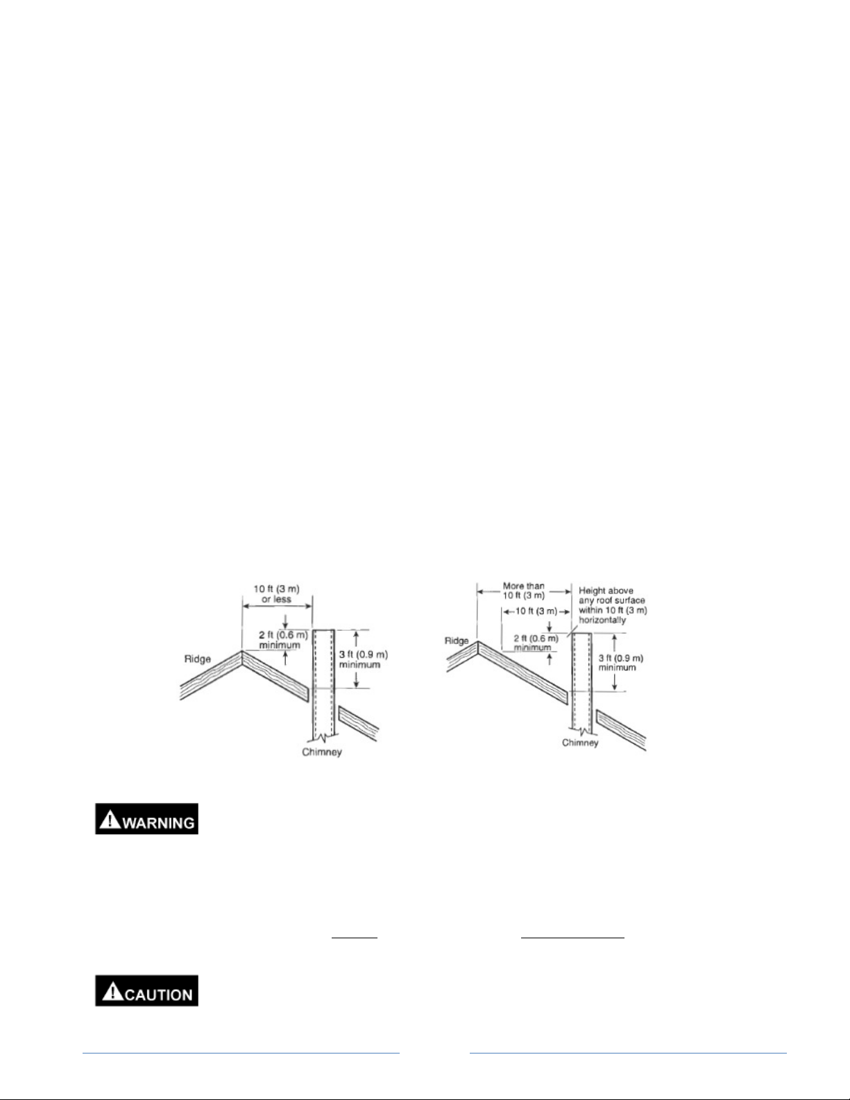
• Roof Line: The vent system must terminate at least 3 feet (0.9 meter) and no more than 6 feet (1.8
meter) above the roof line, and no closer than 8 feet (2.4 meter) from any wall or vertical structure.
Vents extending above the roof more than 5 feet (1.5 meter) should be secured using guy wires or
braces to withstand wind or snow loads.
These units are engineered for natural draft and may not be connected into any
portion of a mechanical or other draft system operating under positive pressure.
Verify that the venting is under negative pressure when all boiler room doors are
closed, the heater/boiler is firing, and all other air using appliances in the room are operating. If the
venting is under positive pressure during operation a draft inducer must be installed, vent material
suitable for positive pressure must be installed and all joints must be sealed.
Common Vent System: Manifolds that connect more than one heater/boiler to a common chimney must be
sized to handle the combined load. At no time should the area of the common vent be less than the area of the
largest heater/boiler exhaust outlet.
Common vent systems may be too large if an existing unit is removed. When an
existing appliance is removed, the vent system design must be carefully evaluated
for proper sizing (Refer to MAINTENANCE Section of this manual).
Page 13

START-UP & OPERATION
Follow these instructions exactly. A fire or explosion may result, potentially causing
personal injury, loss of life and property damage.
Do not use this appliance if any part has been flooded or heavily sprayed with water.
Immediately call a qualified service technician to inspect the controls and replace any
part that has been damaged by water.
PRE-START CHECKLIST
Before starting the boiler, review the following:
• Is the unit properly sized for the application?
• Is the gas supply properly sized and installed?
• Is the vent system properly installed?
• Is the combustion and ventilation air adequate?
• Is the water system properly installed and filled with water?
• Is the proper operation understood and all instructions followed?
This appliance is equipped with an ignition device, which automatically lights the
burner. DO NOT TRY TO LIGHT THE BURNER BY HAND.
FILL THE SYSTEM WITH WATER.
Fill the system with water and purge all air. Trapped air can prevent proper water circulation. Check the water
piping system for leaks and if found, repair immediately.
PURGE AIR FROM GAS LINES
For a new installation, or if the gas lines feeding the heater/boiler were opened to the atmosphere during
installation or service, air in the gas lines must be purged before operating the unit.
Before purging gas lines, ensure electrical power is turned off to the heater/boiler AND ALL OTHER
APPLIANCES IN THE VICINITY OR ROOM. TURN OFF GAS TO ALL APPLIANCES IN THE VICINITY OR
ROOM.
Provide ventilation from the area around the heater/boiler to the outdoors, preferably using
a fan or blower.
Loosen the pipe union or fitting upstream and adjacent to the heater/boiler. Slowly, partially open the manual
gas valve installed upstream of the loosened union or connection. Allow the trapped air to exit the gas piping
until the smell of gas is noticed. Close the manual gas valve and reconnect the pipe union or fitting. Wait at
least 15 minutes before turning electrical power back and/or gas back on to the other appliances, and only after
you are sure purged gases have dissipated.
PREPARATION
1. Ensure the manual gas valve upstream of the heater/boiler is CLOSED.
2. For A2-035 and A2-050 models, ensure the main regulating gas valve is closed.
Before turning on the power to this appliance smell all around the appliance for gas. Be sure to smell
next to the floor because some gas is heavier than air and will collect near the floor.
Page 14

WHAT TO DO IF YOU SMELL GAS:
• Do not try to light any appliance.
• Do not touch any electrical switch; do not use any phone in your building.
• Immediately call your gas supplier from a neighbor’s phone. Follow the gas supplier’s instructions.
• If you cannot reach your gas supplier, call the fire department.
A2-(H,B) 035/050 Main Regulating Gas Valve
Manual Gas Shut-Off Valve, All Other
Models
3. Turn on electrical power to the heater/boiler. Using a multi-meter, check voltage between the HOT and
COMMON (should be about 120 Volts).
4. Check voltage between the HOT and Ground (should be about 120 Volts).
5. Check voltage between the COMMON and Ground (should be less than 1 Volt).
If the COMMON – Ground is more than 1 Volt, STOP! Contact a licensed electrician to
correct the ground fault.
6. Turn OFF electrical power to the heater/boiler.
7. Attach 24 inch manometers to the gas line so that the gas pressure can be measured upstream of the
first heater/boiler automatic gas valve, downstream of the last automatic gas valve, and between
automatic gas valves. NOTE: Depending upon the model, your heater/boiler may be equipped
with one or two automatic gas valves.
8. Install water temperature measurement thermometers in the water inlet and outlet piping.
9. Slowly turn on the manual gas shut off valve upstream of the heater/boiler.
10. Read the gas supply pressure using the manometer. Verify that the supply gas supply pressure is
between the minimum and maximum per the table below. If the pressure is not within these limits,
check to see if a service gas regulator is installed and adjust accordingly.
Maximum Pressure Minimum Pressure
Natural Gas
Propane
Units: Inches of Water
Do not operate heater/boiler if the gas supply pressure is not within the limits shown
in the table above.
11. Turn OFF the manual gas shut off valve upstream of the heater/boiler.
12. Turn ON electrical power to the heater/boiler ON.
13. Turn the operating thermostat to a setting high enough to turn on the water pump. Verify water is
flowing though the heater/boiler by verifying the flow switch has closed.
9 5
15 13
Page 15

14. Turn the operating thermostat to its lowest setting so that water pump stops.
START-UP
1. Slowly turn on the manual gas valve upstream of the heater/boiler. For A2-035 and 050 models only,
turn on the manual valve located on top of the Robertshaw automatic gas valve.
2. Turn the operating thermostat to a setting high enough to turn on the water pump.
3. The ignition control module will turn on the spark ignition system and pilot operating valve to light the
pilot burner. If the pilot does not light the first time, it will retry, up to three times. This is normal during
the initial start-up due to air in the pilot line. If, after trying three times, the pilot burner does not light,
remove power to the ignition module to reset, by either turning the operating thermostat down to its
lowest setting or turning off electrical power to the heater/boiler.
NOTE: CSD-1 models only utilize an ignition module that waits 5 minutes before attempting to
re-light the pilot.
4. After the pilot burner is lit and pilot flame is proven, the Ignition Module will open the automatic main gas
valve(s) and the main burner will light.
If the pilot or main burner fails to light after repeated attempts, shut off the
manual gas valve upstream of the heater/boiler, remove electrical power from
the heater/boiler, and call your qualified service technician or gas supplier.
5. Check for gas leaks in the gas train assembly using soap and water or an appropriate leak check fluid.
DO NOT use an open flame to check for gas leaks.
6. Using the manometers with the heater/boiler operating, check to make sure the gas supply pressure is
within the limits shown above.
7. Check the manifold gas pressure downstream of the automatic gas valves using the outlet pressure tap
provided on the gas valve (A2-035 and 050 models only) or the pressure tap provided in the gas piping.
• For Natural Gas models, the manifold pressure should be set to 4.0” water column.
• For Propane Gas models, the manifold pressure should be set to 10.5” water column.
• For 2-Stage models, see the Operating Section for setting the gas manifold pressure.
a. For A2-035 and A2-050 models, adjust the manifold pressure using the adjustment screw
located on top of the Robertshaw gas valve (remove the dust cover cap to expose the
adjustment screw).
b. For A2-070, 970, 120 and 140 models, adjust the manifold pressure using the Maxitrol gas
pressure regulator located upstream of the automatic gas valve (remove the dust cover cap to
expose the adjustment screw).
c. Replace the manifold pressure adjustment screw caps
8. With the manifold gas pressure set per step 6 above, observe the main burner flame characteristics.
The burner flame should be blue at the base, with yellow at the tips permissible. An excessive amount
of yellow flame suggests a lack of combustion air or inadequate vent draw.
Page 16

9. Verify the water flow switch opens at the minimum water flow rate by slowly closing a manual ball valve
installed in the water outlet piping, until the difference between the water inlet and outlet reaches 95 –
100 oF (53 – 55 oC). Note: The operating thermostat may have to be turned to its highest setting in
order to conduct this test. If the main burner does not shut down when this temperature difference is
achieved, adjust the flow switch set point until the flow switch opens (refer to Operating Section for
instructions concerning setting the flow switch).
10. Fully open the manual ball valve in the water outlet piping.
11. After the main burner has been in operation for at least five (5) minutes, inspect the venting for spillage.
Draft tests must be done with the appliance firing. Proper draft or airflow in the venting may be
determined by either of the following means:
o Smoke Test – Place a source of smoke or other visible fumes under the opening of the draft
hood. If the fumes are all drawn up the draft hood opening, the appliance is drafting properly. If
any fumes roll outside of the vent hood there is a problem with the drafting or make-up air.
o Draft Gauge – A draft pressure gauge can be inserted into the vent pipe directly above the draft
hood. The draft gauge must show a constant negative pressure.
12. Turn the operating thermostat down to its lowest setting. The pilot and main burner will shut off. Close
the manual gas valve immediately upstream of the heater/boiler.
13. Remove the gas pressure manometers and replace all plugs. Use an appropriate pipe thread sealant
(do not use Teflon tape).
14. Open the manual gas valve immediately upstream of the heater/boiler and set the operating thermostat
at the desired temperature.
NOTE: Low inlet water temperatures on start-up may create flue gas condensation which may
gather on the floor under the heater. THIS IS NOT A LEAK. The unit will stop condensating when it
reaches standard operating temperatures.
Main Burner Flame
Pilot Burner Flame
SHUT DOWN PROCEDURE
1. Set the operating thermostat to lowest setting and turn the gas valve to “OFF.”
o For A2-(H,B)-035/050 models, rotating the control knob on top of the combination regulating gas
valve to the “OFF” position turns off the gas.
o For all other models, the gas is turned off by rotating the handle on the separate manual gas
valve to a position perpendicular to the gas piping.
2. Switch off all electrical power to the system.
Page 17

OPERATION
The A2000 models are simple ON/OFF water heater/boilers. The units are turned ON and OFF by the
application or removal of 120 VAC power to the control panel. Normally, this 120 VAC power is provided
through an operating thermostat. Safety controls (such as a flow switch and manual reset water high limit
temperature switch) installed between the operating thermostat and the heater/boiler prevent power from
reaching the control panel if water flow is not present, or the outlet water temperature has been exceeded.
When 120 VAC power is applied to the heater/boiler control panel on a call for heat from the operating
thermostat, 24 VAC is applied to the Ignition Control Module via a transformer. The ICM provides spark to the
igniter, opens the pilot burner operating valve providing gas flow to the pilot burner, and looks for flame
verification through the spark igniter electronics. Once pilot flame is verified, the ICM opens the automatic main
burner valve(s), which provides gas flow to the main burner, which is ignited by the pilot burner.
Ignition Control Module (ICM)
normally closed pilot valve and main burner valves close.
Operating Thermostat Setting: A separate operating temperature controller is required for proper operation of
this appliance. Failure to install a separate operating temperature controller will result in short cycling. Water
heaters are expected to operate at temperatures between 120 °F and 155 °F (49 to 68 oC) Water boilers can
operate with return water temperature up to 190 °F (88 oC) and a supply temperature up to 240 oF (115 oC).
Return water temperatures must be kept above 120 °F to prevent condensation. Refer to the DIAGRAMS
section for recommended piping for lower operating water temperatures. Frequent operation below 120°F (49
o
C) return water temperature will damage the heat exchanger and void the warranty.
Do not operate your A2000 heater/boiler with return water temperatures lower than
120 oF (49 0C). Consistent operation below these temperatures will cause heat
exchanger corrosion and void the warranty.
Water Temperature - Scald Relationship
Water Time to Produce
Temperature 2nd & 3rd Degree
deg F deg C
> 170 > 77
160 71
150 65
140 60
130 54
120 49
Water High Limit Switch: Every A2000 model is equipped with a manual reset, High Limit Switch on the hot
water outlet. For water heater models, the high limit has a factory stop of 200 oF (93 oC). For boiler models, the
factory stop is set at 240 oF (115 oC). The high limit switch must always be present and must never be bypassed. If the High Limit Switch trips, it must be manually reset by pressing the red button, located on the front
cover of the High Limit Switch.
Burns on Adult Skin
Nearly Instantaneous
About 1/2 Second
About 1-1/2 Second
Less Than 5 Seconds
About 30 Seconds
More Than 5 Minutes
If the pilot flame is not verified, the ICM will try to light the pilot burner two
more times (see CSD-1 Section below for control differences specific to
CSD-1 models). After the third try, the ICM will go into lock-out. The ICM
can be reset by removing power to the heater/boiler. The pilot burner
remains ON the entire time the main burner is ON. If pilot flame verification
is lost while the main burner valves are ON, the ICM will close the main
burner valves and try to re-establish pilot burner flame.
When the operating thermostat is satisfied, the 120 VAC is removed, and the
When the heater/boiler is used for potable water heating, use a
mixing valve or similar means to reduce the potable water
supply temperature to avoid scald injuries. The mixing valve
should be set at the lowest possible temperature that provides
useful service for the application. For potable water uses, 120
– 125o F (49 – 51o C) is recommended.
Water temperatures higher than 125 oF
(51 oC) can cause severe burns,
personal injury or loss of life. The
temperature at which injury occurs
varies with a persons age and the time of exposure. Never
allow small children to use a hot water tap or draw their
own bath water.
Page 18

Gas Pressure Regulator: A gas pressure regulator is provided on all A2000 water heater/boilers. This regulator
is preset at 4 inches water column for natural gas or 10.5 inches water column for Propane gas. For
A2(H,B)035/050 models, the pressure may be adjusted using the adjustment screw located on the combination
gas valve (see Figure on page 16). For all other models, except 2-Stage, a Maxitrol gas pressure regulator is
provided. If a pressure adjustment is required, remove plug and turn screw clockwise to increase pressure,
counterclockwise to decrease pressure. One complete turn will change the pressure approximately ¼ inch of
water column. For 2-Stage models, see the Items Specific to 2-Stage Models below.
Flow Switch: A flow switch is required to be installed in the outlet water line, wired so that the heater/boiler will
not fire unless the minimum water flow through the heat exchanger is present. The minimum flow rate for each
model the flow that will provide a 100 oF (55 oC) temperature rise through the heat exchanger (see table in
Water Pump: All A2000 models require forced circulation of the water through the heat exchanger. Selection
and installation method of the pump depends upon the design of the system and intended use (see DIAGRAMS
section for water pump location suggestions). The pump electrical power must be wired independently and
should be adequate for the amp rating of the pump motor. Refer to the INSTALLATION section for pressure
losses through the A2000 heat exchangers. The maximum flow rate through the A2000 heat exchanger is
56 gpm due to velocity induced tube erosion. A list of acceptable water pumps and manufacturers for
the A2000 models is listed on the following page.
Water High Limit Switch –
Manual Reset
Operation of the A2000 heater/boiler at gas manifold pressures greater than 4.0” w.c.
for Natural Gas, and 10.5” w.c. for Propane Gas, will cause the unit to be over-fired,
which may cause premature heat exchanger failure, serious injury, or loss of life.
INSTALLATION Section). The set point for the flow switch can be
changed using the adjustment screw located under the electrical house
cover of the switch. Rotate the screw clockwise to increase the flow
set point, counter-clockwise to decrease the flow set point. With the
heater/boiler firing (make sure 2-Stage models are firing on HIGH),
slowly close the manual valve in the water outlet piping, until the
temperature rise through the heat exchanger approaches 100 °F (or
lower based on specific installation or requirements). Adjust the switch
set point so that the switch opens at this flow rate. Slowly open the
water valve so that the switch closes, then repeat the process to
ensure the switch is set correctly.
Risk of electrical shock. Be careful not to touch live electrical parts or bare wires
inside the flow switch housing. The voltage to the flow switch is 120 VAC.
Maxitrol Gas Pressure Regulator
Page 19

A2000 Pump Selection Chart
MODEL: A2*035* A2*050* A2*070* A2*097* A2*120* A2*140*
Flow Rate &
Head Loss
Pump Vendor
GOULDS : 1ST2C1D4 1ST2C1D4 1ST1C1E4 2ST1E1E4
Horsepower 1/2 1/2 1/2 1 1-1/2 1-1/2
RPM 1750 1750 3450 3450 3450 3450
Electric 115/230 VAC 115/230 VAC 115/230 VAC 115/230 VAC 115/230 VAC 115/230 VAC
Impeller 4-3/4" 4-3/4" 4-7/16" 4-1/4" 4-5/8" 4-5/8"
B & G :
Horsepower 1/2 1/2 1 2 3 3
RPM 1750 1750 3500 3500 3500 3500
Electric 115 VAC 115 VAC 115 VAC 115 VAC 115 VAC 115 VAC
Impeller 3-7/8” 3-7/8” 3-7/8” 4-5/8” 4-3/4” 4-3/4”
GRUNDFOS :
Horsepower 1/12 1/6
RPM 3450 3450
Electric 115 VAC 115 VAC
Impeller One Size Only One Size Only
TACO :
Horsepower 1/8 1/8
RPM 3250 3250
Electric 115 VAC 115 VAC
Impeller One Size Only One Size Only
BURKS :
Horsepower 1/3 1 1 1
RPM 3500 3500 3500 3500
Electric 115/230 VAC 115/230 VAC 115/230 VAC 115/230 VAC
Impeller 3-1/8” 4-1/8” 4-1/8” 4-1/8”
MEPCO :
Horsepower 1/2 1 1-1/2 1-1/2
RPM 3450 3450 3450 3450
Electric 115/230 VAC 115/230 VAC 115/230 VAC 115/230 VAC
Impeller 3-1/2" 4-1/2" 5" 5"
23GPM @
11.3 FT.
3530
1-1/4x1-1/2x6
UP26-96BF UP43-75BF Not Available Not Available Not Available Not Available
0012BF4 0012BF4 Not Available Not Available Not Available Not Available
Not Available Not Available 3GA5-1 1/4AB 10GA5-1 1/4AB 10GA5-1 1/4AB 10GA5-1 1/4AB
Not Available Not Available RC05-10
23GPM @
11.3 FT.
3530
1-1/4x1-1/2x6
40GPM @
34.6 FT.
3530
1-1/4x1-1/2x6
-005-34-1
49GPM @
54.8 FT.
3530
1-1/4x1-1/2x6
RC05-10
-010-34-1
54GPM @
70.7 FT.
2ST1F1D4
3530
1-1/2x2x6
RC05-10
-015-34-1
40GPM @
70.7 FT.
2ST1F1D4
1-1/2x2x6
RC05-10
-015-34-1
3530
Page 20

Relief Valve Operation: Each boiler/water heater is equipped with an ASME approved pressure relief valve,
with a standard setting of 125 psi (862 kPa). The outlet of the relief valve must be piped to a drain or other
suitable safe place in accordance with local codes. When the heater/boiler is connected to a storage tank, a
separate temperature/pressure relief valve must be provided on the tank.
Items Specific To CSD-1 Models: A2000 models equipped with ASME CSD-1 gas train and controls (model
numbers start with “A2C”) include a factory installed water flow switch in the water hot water outlet, and an
operating thermostat (240 oF (115 oC) maximum setting) in the cold water inlet. CSD-1 models are also
equipped with an Ignition Control Module (ICM) that waits five minutes before trying to re-light the pilot burner.
The CSD-1 ICM will not lock out on flame failure; it will continually try to re-light the pilot burner every five
minutes.
Items Specific to 2-Stage Models: Natural Gas A2000 models equipped with a 2-Stage gas valve (model
numbers starting with “A2T” or “A2X”) include an electronic temperature controller with its temperature sensor
installed in the inlet water line. 24 VAC power for the automatic gas control valve, from the ICM, passes through
electronic temperature controller, to either the LOW or HIGH terminal of the 2-Stage gas valve. The 2-Stage
gas valve is factory set to provide 4 inches w.c. gas pressure in HIGH fire mode, and 2.0 inches w.c. in the LOW
fire mode (approximately 70% of nameplate input).
The electronic controller is factory set with both stages in Heating Mode, with Stage 2 set for HIGH fire, and
Stage 1 set for LOW fire. The factory temperature and differential settings are provided in the table below.
Electronic 2-Stage
Temperature Controller
2-Stage Controller - Factory Set Points
Stage 1 (Low Fire OFF) Set Point 180 oF
Stage 1 Differential 45 oF
Stage 2 (High Fire OFF) Set Point 135 oF
Stage 2 Differential 95 oF
Low Fire Range: 135 oF to 180 oF
High Fire Range: 40 oF to 135 oF
When the control is in heating mode, the differential is below the set point.
The relay will de-energize as the temperature rises to the set point.
To change the settings, press the SET button. The screen will display oF or
o
C, press the ▲or ▼key to change the mode. Press the SET button again to
display the Stage 1 (S1) set point. Press the ▲or ▼key to change the set
point, then press SET. The S1 differential will not be displayed. Press the
▲or ▼key to change the differential, then press SET. The heating (H1) or
cooling mode (C1) will be displayed. Press SET to keep the control in heating
Electronic 2-Stage Temp
Controller – Heating Mode
mode. Press SET again to display the Stage 2 (S1) set point. After setting the
desired temperature, press SET again to display the S2 differential. Press set
again to display heating (H2) or cooling (C2) mode. Press SET to keep control
in heating mode.
Programming is now complete. Programming mode will end if no keys are
pressed for 30 seconds. Any changes will be saved. Settings are stored in
non-volatile memory and will not be lost with power failure.
Page 21

MAINTENANCE & INSPECTION
This manual must be thoroughly reviewed and understood before servicing your A2000
heater/boiler. Installation and Service must be completed by a Qualified Installer, Service
Agency or Qualified Gas Supplier. If you have any questions which are not covered in the
manual, please contact Green Boiler Technologies or your local Representative.
Keep the area clear and free from combustible materials, flammable liquids and
vapors. Do not block the flow of combustion air by blocking air vents or by storing
boxes or other items near the appliance.
Label all wires before disconnection when servicing controls. Wiring errors can
cause improper and dangerous operation.
Verify proper operation of the heater/boiler after any inspection or servicing the
appliance.
Heat Exchanger: The heat exchanger should be visually checked at least once a year, or whenever necessary.
The heat exchanger can be viewed from the top of the unit by removing the draft hood. The fins on the heat
exchanger tubing should extend about 27/64 of an inch. Excessive burn off of fin height indicates poor heat
transfer, commonly caused by scaling (deposits of lime and other minerals) inside the tube. Look for corrosion
(usually a rusty-brown coating) commonly caused by cleaning solvent vapors or fumes in the combustion air
supply), or sooting (a fine black-gray powder caused by improper combustion, usually due to a partially blocked
stack or insufficient combustion air), or the affect of excessive condensation (usually evidenced by a greenishblack cupro oxide caused by the acid formed by the mixing of combustion gases with the condensate).
Before removing draft hood, ensure that the gas and electrical power to the
heater/boiler is shut off.
Burner & Pilot Flame: The burner and pilot flame should be checked frequently (it is recommended that the
unit be checked at least annually by a professional service technician). A yellow flame commonly indicates poor
combustion, and may cause soot deposits on the heat exchanger or inside the venting. When an excessively
yellow flame is present, inspect the burner orifices and heat exchanger for carbon deposits and foreign particles.
Yellow flame and sooting may be caused by inadequate combustion air, venting, or incorrect gas manifold
pressure. Refer to the burner and pilot flame Figure in the START-UP Section of this manual.
Gas Manifold Pressure: Check the gas manifold pressure at least once per year to make sure it matches that
specified on the Name Plate, using an manometer (refer to START-UP Section for checking manifold pressure).
Vent System: Inspect the venting system for proper size, horizontal pitch and determine there is no blockage or
restriction, leakage, corrosion or any other deficiencies which could cause an unsafe condition. Check the inside
of the vent system for excessive sooting.
In so far as practical, close all building doors between the space in which the appliances are connected
to a common venting system and any area where any appliance which is not connected to the common
venting system is located. Test the system by turning on clothes dryers and any other appliance not
connected to the common venting system. Turn on all exhaust fans, including those used in range
hoods and bathroom exhausts, so they will operate at their maximum speed. Close fireplace dampers.
Place the appliance being tested into operation by following the proper lighting instructions. Adjust the
aquastat so the appliance will remain in operation for the duration of the test. After the main burner has
been in operation for at least five (5) minutes. inspect the venting for spillage. When it is determined the
unit is working without exhaust gasses spilling into the room, return doors, windows, fans, fireplace
dampers and any other gas-burning device to their normal condition of use.
Draft tests must be done with the appliance firing. Proper draft or airflow in the venting may be
determined by either of the following means:
Page 22

o Smoke Test – Place a source of smoke or other visible fumes below the opening of the draft
hood. If the fumes are all drawn up the draft hood opening, the appliance is drafting properly. If
any fumes roll outside of the vent hood there is a problem with the drafting or make-up air.
o Draft Gauge – A draft pressure gauge can be inserted into the vent pipe directly above the draft
hood. The draft gauge must show a constant negative pressure.
Any improper operation of common venting systems should be corrected so the installation conforms to
the National Fuel Gas Code, ANSI-Z223.1, Latest Edition. When any portion of the venting system is
changed it must conform to the National Fuel Gas Code, ANSI-Z223.1, Latest Edition.
Burner & Flue Passageway: Do not allow the burner, burner orifices, or the floor shield to accumulate foreign
matter. Clean periodically by brushing or blowing any dust or debris from the area. Orifices should be checked
for size and reamed as required. The flue gas passageway can be cleaned by simply sliding the burner out and
flushing the finned tubing with water.
Before disconnecting the burner, be sure to shut off all gas valves and electrical
switches then let cool for 30 minutes. After cleaning, reinstall the burner. Water must
be circulating before turning on the gas valve to prevent heat exchanger damage.
Pressure Relief Valve: A pressure relief valve is supplied on the outlet of the heat exchanger. The relief valve
should be tested at least annually by lifting the test handle.
When testing the valve extremely hot water and/or steam may be released.
High Temperature Switch: The manual reset High Temperature switch, located in the water outlet piping,
should be checked annually for proper function. To test the switch, slowly close the valve in the water outlet
piping until the water temperature exceeds the set point of the switch. The temperature switch should open
before the water temperature reaches 210 oF (99 oC) for a water heater, and 250 oF (121 oC) for a boiler. Note:
The operating thermostat and/or flow switch may have to be temporarily by-passed in order to conduct this test.
Ensure all operating and safety controls are put back into proper operation before
putting the heater/boiler back into service.
Flow Switch: The water Flow Switch should be checked annually for proper function. To test the Flow Switch,
slowly close the valve in the water outlet piping until the temperature rise through the heat exchanger
approaches 100 oF (55 oC). The Flow Switch should open before the temperature rise exceeds 105 oF (58 oC).
Refer to the OPERATION Section of this manual for more information regarding the water Flow Switch.
Heat Exchanger Protection: Either very soft or very hard water will shorten the life of the heat exchanger. The
water to be heated should be between 5 and 15 grains per gallon. Harder water should be softened to prevent
scaling, reduced efficiency and ultimately melting the heat exchanger. Softer water must have buffers added to
prevent erosion of the heat exchanger. NOTE: FAILURE TO PROPERLY OBSERVE THE ABOVE WILL VOID
THE WARRANTY AND MAY RESULT IN A VERY SHORT LIFE OF THIS BOILER/HEATER.
Condensation: Condensation of the flue gas may result if the inlet water temperature is under 120° F.
Condensation will form on the outside of the heat exchanger and drip down onto the burner and possibly the
floor below the heater/boiler, often mistaken for a leaking coil. After the boiler has been in operation long
enough for the temperature of the water in the system to reach 120° F, the condensation will stop dripping from
the heat exchanger. The A2000 and the venting connected to it are not designed to withstand repeated
condensation. Low operating temperatures and frequent cold start-ups must be prevented. Frequent operation
below 120°F return water temperature will damage the heat exchanger and void the warranty. If low operating
temperatures cannot be avoided, a feedback loop (by-pass) must be installed as shown in the DIAGRAMS
section.
Noise During Operation: Knocking sounds produced by the heater/boiler may indicate scale build-up in the
heat exchanger waterway. De-liming is recommended. Scale thickness as thin as 1/16 inch can increase fuel
consumption by 15%. Refer to procedure provided with de-liming kit part number W3700001. Extended
operation with a scaled heat exchanger may cause early heat exchanger failure and will void warranty.
Page 23

Removal of Existing Appliance: If an existing appliance is removed from a common venting system, the
common venting system is likely to be too large for proper venting of the appliances remaining connected to it.
At the time of removal, the following steps shall be followed with each appliance remaining connected to the
common venting system placed in operation, while the other appliances remaining connected to the common
venting system are not in operation.
(a) Seal any unused openings in the common venting system.
(b) Visually inspect the venting system for proper size and horizontal pitch, and determine there is no
blockage or restriction, leakage, corrosion and other deficiencies which could cause an unsafe
condition.
(c) Insofar as is practical, close all building doors and windows and all doors between the space in which
the appliances remaining connected to the common venting system are located and other spaces of the
building. Turn on clothes dryers and any appliance not connected to the common venting system. Turn
on any exhaust fans, such as range hoods and bathroom exhausts, so they will operate at maximum
speed. Don not operate a summer exhaust fan. Close fireplace dampers.
(d) Place in operation the appliance being inspected. Follow the lighting instructions. Adjust thermostat so
appliance will operate continuously.
(e) Test for spillage at the draft hood relief opening after 5 minutes of main burner operation. Use the flame
of a match or candle, or smoke from a cigarette, cigar or pipe.
(f) After it has been determined that each appliance remaining connected to the common venting system
properly vents when tested as outlined above, return doors, windows, exhaust fans, fireplace dampers
and any other gas-burning appliance to their previous condition of use.
(g) Any improper operation of the common venting system should be corrected so the installation conforms
with the National fuel Gas Code, ANSI Z223.1/NFPA 54 and/or CAN/CSA B149.1, Natural Gas and
Propane Installation Code. When resizing any portion of the common venting system, the common
venting system should be resized to approach the minimum size as determined using the appropriate
tables in Part 11 of the National fuel Gas Code, ANSI Z223.1/NFPA 54 and/or CAN/CSA B149.1,
Natural Gas and Propane Installation Code.
Page 24

SYMPTOM POSSIBLE CAUSE CHECKS & REMEDIES
Short Cycling (Unit
Turns ON And OFF
Every 30 seconds Or
So).
The Unit Will Not
Operate
Operating Aquastat Not
Operating Aquastat
Installed In The Wrong
System Mis-Wired Or
Operating Aquastat
Has Failed
Pilot Burner Is Not
Pilot Lights But Main
Burner Will Not Come
No Power To The Unit
No Power To The
Transformer
No Power To The
Ignition Module
TROUBLESHOOTING
Install An Operating Aquastat Or Boiler Sequencer To
Installed
For a Storage Tank Installation, Install the Operating
Aquastat in the Tank. Otherwise, the Operating Aquastat
Location
Being Lit
On
Must Be Installed Upstream of the A2000 In A Place That
Will Have Constant Water Flow Across The Sensor
When The Desired Operating Temperature has Been
Reached, The 120 VAC Electrical Power Supplied To the
Appliance Should Be Interrupted. If The Power Is Not
Stopped At The Desired Operating Temperature, Correct
The Wiring Or Replace The Defective Temperature Switch.
Refer to “Pilot Burner Not Lighting” In The Symptoms Listed
Refer To “Main Burner Not Lighting” In the Symptoms Listed
Use A Multimeter To Check For 120 VAC Power To The
Unit When It is Supposed To Be Turned ON. Trace The
Check The Manual Reset High Temperature Switch. Reset
Verify 120 VAC Power To The Transformer. Replace
Page 25
Control The Water Temperature
Below.
Below.
Interruption Of Power Back To the Source.
Or Replace As Necessary
Transformer If Needed.

SYMPTOM POSSIBLE CAUSE CHECKS & REMEDIES
Pilot Burner Not
Lighting
The Pilot Is Lit, But
Goes Out After 15
Seconds Or Less. The
Main Burner Never
Comes On
The Ignition Module Is
Not Generating A Spark
The Spark Is Not Arcing
In The Proper Location
The Ignition Cable Is
A Crack In The Pilot
Burner Assembly Is
Preventing Flame
Gas Valve Mis-Wired
Poor Ground
Broken
Sensing
Verify That The Red Spark Cable Is Securely Attached To
The Ignition Module And The Pilot Burner.
Verify The Red Spark Cable Is Not Cracked Or Broken.
Replace If Necessary.
Verify that the Ignition Module Is Receiving 24 VAC Power
Across The Blue and Yellow Wires, And Listen For Sparks
For 15 Seconds After Being Powered. If The Module Does
Not Generate A Spark When Powered, Replace The
Ignition Module.
Verify That The Unit Is Properly Grounded. Remove The
Burner Assembly And Inspect The Pilot Burner Assembly.
Clean Any Residue From The Spark Rod and Striking Plate
With a Scotch Brite Pad. Use A 1/8” Drill Bit to Make Sure
The Gap Between The Spark Rod and Striking Plate Is
Exactly 1/8”. If any Crocks Are Observed In The Ceramic,
Or If Cleaning And Gapping fail To Correct The Problem,
Replace The Pilot Burner Assembly.
Make Sure The Appliance Is Properly Grounded
Replace Ignition Cable
Replace The Pilot Burner Assembly
Check The Unit Wiring Against The Appropriate Wiring
Schematic And Correct Any Problems
Page 26

SYMPTOM POSSIBLE CAUSE CHECKS & REMEDIES
The Pilot Is Lit And
Stays ON, But The
Main Burner Never
Comes ON
Hot Spots On The
Jacket Or Flames
Rolling Out From The
Base Of The Unit
Manual Reset High
Temperature Switch
Keeps Tripping Off
The Bleed Line On One
Of The Gas Valves Is
The Ignition Module Is
The Gas Valve Is
Gas Valve(s) Mis-Wired
Heat Exchanger Fins
Inadequate Make-Up
(Combustion) Air
Improper Vent
Operating Aquastat Is
Not Set More Than
35oF Below The High
Temperature Limit
Switch Set Point (200oF
For Water Heaters)
(240 oF For Boilers)
Plugged
Defective
Defective
Clogged
Installation
Clogged Vent
(Only For Honeywell V88 Gas Valves) Temporarily
Disconnect The 1/8” Bleed Line From Each Gas Valve. If
The Appliance Operates Properly, Clear Or Replace The
Bleed Lines.
Check The Wires To The Gas Valves For 24 VAC When
The Pilot Is Lit. If No Power Found, Replace The Ignition
Module
Check The Wires To The Gas Valves For 24 VAC When
The Pilot Is Lit. If The Valves Are Receiving Power But Not
Operating, Replace The Defective Valve
Check The Unit Wiring Against The Appropriate Wiring
Schematic And Correct Any Problems
Cover The Burner And Controls And Clean The Heat
Exchanger With A Wire Brush Or High Pressure Water.
Prevent Future Fouling Of The Heat Exchanger By
Preventing Condensation Or Removing Contaminants From
The Air Supply. Refer To MAINTENANCE & INSPECTION
Section Of This Manual. Replace Jacket & Insulation As
Required.
Make Sure The Combustion Make-Up Air Openings Meet
The Requirements Discussed In The INSTALLATION
Section Of This Manual.
Make Sure The Exhaust Vent System Meets The
Requirements Discussed In The INSTALLATION Section Of
This Manual.
Inspect Vent System For Flow Blockages. Clean & Remove
Blockages As Required
Make Sure The High Limit Switch Is Set To The Highest
Setting. Ensure The Operating Thermostat Is Set At Least
35 oF Below The High Temperature Switch Set Point.
Page 27

SYMPTOM POSSIBLE CAUSE CHECKS & REMEDIES
The Flow Switch
Keeps Tripping Or Will
Not Close
An Appliance That Has
Been In Operation For
Over A Year Starts To
Have Any Of The
Following Symptoms:
Stack Temperature
Over 450 oF, A Water
Temperature Rise
Through The Heat
Exchanger More Than
5 oF (3 oC) Rise Higher
Than Originally Set, Or
Trouble Proving Water
Flow
Knocking Sounds
From The Heat
Exchanger
Water Flow Rate Too
Excessive Scaling
Inside The Heat
Flow Switch Set
Excessive Scaling
Inside The Heat
Excessive Scaling
Inside The Heat
Low
Exchanger.
Incorrectly
Exchanger
Exchanger
Ensure Valves In The Water Lines Are Open
Ensure The Pump Is Operating Correctly. Replace Or
Upgrade Pump If Required.
The Heat Exchanger Should Be De-limed. Contact Your
Local Green Boiler Representative For Assistance. Refer
To The INSTALLATION And MAINTENANCE Sections Of
This Manual For Information To Prevent Future Heat
Exchanger Scaling.
Adjust Flow Switch Set Point. Refer To OPERATION
Section Of This Manual
If One Of The Symptoms Occurs, Check For The Other
Symptoms. If Two Or More Happen At The Same Time,
The Heat Exchanger Should Be De-limed. Contact Your
Local Green Boiler Representative For Assistance. Refer
To The INSTALLATION And MAINTENANCE Sections Of
This Manual For Information To Prevent Future Heat
Exchanger Scaling.
The Heat Exchanger Should Be De-limed. Contact Your
Local Green Boiler Representative For Assistance. Refer
To The INSTALLATION And MAINTENANCE Sections Of
This Manual For Information To Prevent Future Heat
Exchanger Scaling.
Refer to De-Liming Procedure Included With Kit Number
W3700001
Page 28

DIAGRAMS
Page 29

Page 30

FEEDBACK LOOP (BY-PASS) PLUMBING FOR LOW TEMPERATURE SYSTEMS
1. Set Operating (Controlling) Thermostat to the desired return temperature.
2. Open all water valves.
3. Watch the temperatures at Thermometer ‘A’ and the T&P Gauge on the Heater/Boiler Outlet.
4. Adjust valve ‘B’ in small increments until the temperature reading at the T&P Gauge is about 80 oF
higher than the temperature measured at Thermometer ‘A’. (The Heater/Boiler must be firing
continuously during this adjustment. Thermometer readings may be inaccurate if the Heater/Boiler
cycles frequently).
5. Monitor Operation of the Heater/Boiler and the water temperature until the system reaches the desired
operating temperature.
6. If the Heater/Boiler cycles ON and OFF more than once every few minutes, contact the Customer
Service for further assistance.
Page 31

WIRING DIAGRAM
A2000 Water Heater Models
Page 32

WIRING DIAGRAM
A2000 Boiler Models
Page 33

WIRING DIAGRAM
A2000 CSD-1 Boiler Models
Page 34

A2000 WITH CONSTANT PUMP OPERATION
A2000 WITH ON-OFF PUMP OPERATION
Page 35

A2000 WITH INFITEC PUMP DELAY
Page 36

1
17
19
15
23
22
21
20
18
16
4
2
7
14
5
A2000 PARTS LIST
Gas Train,
Components
Differ By Model
Page 37

A2000 PARTS LIST
ITEM
1 W5501005 Draft Hood, 9” A2-035
2 W1653010 125 PSI Pressure Relief Valve, ¾” A2-(035-070)
3 W2102025 Manual Reset High Limit Switch, 200 oF A2-(H,T)(035/140)
4 W1651000 Boiler Drain Valve, ¾” All Models
5 W1751026 Automatic Gas Valve, 1” A2C035, A2(B,C,X)050
6 W5501102 NG Gas Pressure Regulator, 1” RV61 A2C-(035,050)-NG
7 W1751014 Combination Gas Valve, Main & Pilot, NG A2(H,B)-(035,050)-NG
8 W1751021 Pilot Valve All Except A2(H,B)-(035,050)
9 W2500005 Burner Orifice, NG #53 NG Models Except High Altitude
10 W1800002 Burner With Orifices, A2-035-NG A2-035-NG
PART
NUMBER
W5501006 Draft Hood, 10” A2-050
W5501000 Draft Hood, 12” A2-070
W5501001 Draft Hood, 16” A2-097
W5501001 Draft Hood, 16” A2-120
W5501002 Draft Hood, 18” A2-140
W1653014 125 PSI Pressure Relief Valve, 1” A2-(097-140)
W2102003 Manual Reset High Limit Switch, 240 oF A2-(B,C,X)(035/140)
W1751013 Automatic Gas Valve, 1-1/4” A2(H,B,C,X)(070,097)
W1751024 Automatic Gas Valve, 1-1/2” A2(H,B,C,X)(120,140)
W1751022 2-Stage Gas Valve, 1” NG A2(T,X)(035,050)NG
W1751023 2-Stage Gas Valve, 1-1/4” NG A2(T,X)(070,097)NG
W1751025 2-Stage Gas Valve, 1-1/2” NG A2(T,X)(120,140)NG
W5501106 LP Gas Pressure Regulator, 1” RV61 A2C(035,050)-LP
W5501103 NG Gas Pressure Regulator, 1-1/4” RV61 A2-070-NG
W5501107 LP Gas Pressure Regulator, 1-1/4” RV61 A2-070-LP
W5501104 NG Gas Pressure Regulator, 1-1/4” RV81 A2-097-NG
W5501108 LP Gas Pressure Regulator, 1-1/4” RV81 A2-097-LP
W5501105 NG Gas Pressure Regulator, 1-1/2” RV81 A2-(120,140)-NG
W5501109 LP Gas Pressure Regulator, 1-1/2” RV81 A2-(120,140)-LP
W5501111 Combination Gas Valve, Main & Pilot, LP A2(H,B)-(035,050)-LP
W1751038 Manual Gas Valve, 1/8” Most Models
W2500004 Burner Orifice, LP #66 LP Models Except High Altitude
W2500007 Burner Orifice, Blank High Altitude Models, Drill To Order
W2500006 Burner Orifice, Special Stainless Steel All Models, Drill To Order
W1800011 Burner With Orifices, A2-035-LP A2-035-LP
W1800003 Burner With Orifices, A2-050-NG (2 Req) A2-050-NG
W1800012 Burner With Orifices, A2-050-LP (2 Req) A2-050-LP
W1800004 Burner With Orifices, A2-070-NG (2 Req) A2-070-NG
W1800013 Burner With Orifices, A2-070-LP (2 Req) A2-070-LP
W1800005 Burner With Orifices, A2-097-NG (2 Req) A2-097-NG
W1800020 Burner With Orifices, A2-120-NG (2 Req) A2-120-NG
W1800021 Burner With Orifices, A2-140-NG (2 Req) A2-140-NG
W1800016 Burner With Orifices, A2-140-LP (2 Req) A2-140-LP
DESCRIPTION
USE ON MODEL
Page 38

A2000 PARTS LIST - Continued
ITEM
11 W1950023 Pilot Burner Assembly, NG All NG Models
12 W1950081 Ignition Control Module S8600H All Models Except CSD-1
13 W2250003 Transformer, 120/24 VAC, 40VA All Models
14 W1751051 1” Gas Valve, Manual w/Pressure Tap A2-(035,050)
15 W4501018 Top Outer Lid - Stainless A2-035
16 W4501306 Outer Jacket - Stainless A2-035
17 W4501080 Cover Control Box All Models
18 W4501164 Insulation, Shell 24 x 78” A2-035
19 W4501010 Top, Inner Lid A2-035
PART
NUMBER
W5501112 Pilot Burner Assembly, LP All LP Models
W4501050 Pilot Mounting Bracket, A2-035 A2-035
W4501051 Pilot Mounting Bracket, A2-050 A2-050
W4501052 Pilot Mounting Bracket, A2-070 A2-070
W4501053 Pilot Mounting Bracket, A2-(097-140) A2-(097-140)
W1950082 Ignition Control Module S8600M A2C(035-140)
W1950028 Ignition Cable, 30” All Models
W1751052 1-1/4” Gas Valve, Manual w/Pressure Tap A2-(070,097)
W1751053 1-1/2” Gas Valve, Manual w/Pressure Tap A2-(120,140)
W4501019 Top Outer Lid - Stainless A2-050
W4501020 Top Outer Lid - Stainless A2-070
W4501021 Top Outer Lid - Stainless A2-097
W4501023 Top Outer Lid - Stainless A2-120
W4501024 Top Outer Lid - Stainless A2-140
W4501307 Outer Jacket - Stainless A2-050
W4501308 Outer Jacket - Stainless A2-070
W4501309 Outer Jacket - Stainless A2-097
W4501310 Outer Jacket - Stainless A2-(120,140)
W4501031 Bracket, Control Box Mounting All Models
W4501166 Insulation, Shell 30 x 90” A2-050
W4501168 Insulation, Shell 27.5 x 112” A2-070
W4501170 Insulation, Shell 27.5 x 112” A2-097
W4501172 Insulation, Shell 34 x 112” A2-(120,140)
W4501165 Insulation, Top 24 x 24” A2-035
W4501167 Insulation, Top 28 x 28” A2-050
W4501169 Insulation, Top 32 x 32” A2-070
W4501171 Insulation, Top 34 x 34” A2-097
W4501173 Insulation, Top 36 x 36” A2-(120,140)
W4501011 Top, Inner Lid A2-050
W4501012 Top, Inner Lid A2-070
W4501013 Top, Inner Lid A2-097
W4501015 Top, Inner Lid A2-120
W4501016 Top, Inner Lid A2-140
DESCRIPTION
USE ON MODEL
Page 39

A2000 PARTS LIST - Continued
ITEM
20 W5501066 Heat Exchanger Assy A2-035 * A2-035
W5501067 Heat Exchanger Assy A2-050 * A2-050
W5501068 Heat Exchanger Assy A2-070 * A2-070
W5501069 Heat Exchanger Assy A2-097 * A2-097
W5501071 Heat Exchanger Assy A2-(120,140) * A2-(120,140)
21 W4501182 Inner Front Panel A2-035
22 W4501085 Inner Jacket A2-035
23 W5501088 Flue Baffle (Cone) A2-035
W3700001 Deliming Kit All Models
For NG to LP or LP to NG Conversion Kits, Call Your Green Boiler Technologies Representative or the
PART
NUMBER
*
Heat Exchanger Assemblies Include Inner Front Panel, Inner Jacket and Flue Baffles
W4501064 Inner Front Panel A2-050
W4501062 Inner Front Panel A2-070
W4501183 Inner Front Panel A2-097
W4501296 Inner Front Panel A2-(120,140)
W4501086 Inner Jacket A2-050
W4501087 Inner Jacket A2-070
W4501089 Inner Jacket A2-097
W4501088 Inner Jacket A2-(120,140)
W5501041 Flue Baffle (Cone) A2-050
W5501040 Flue Baffle (Cone) A2-070
W5501035 Flue Baffle (Cone) A2-(097-140)
W4501072 Flue Baffle (Stainless Strip, 96” Section) All Models
W2000002 Module, Pump Delay All Models
W2101001 Water Flow Switch All Models
W2103031 Combination Temp & Pressure Gauge All Models
W2102002 Operating Aquastat, 240 oF All Models
W2102018 Electronic Temp Controller, 2-Stage 2-Stage Models
DESCRIPTION
Customer Service Number
Accessories
USE ON MODEL
Fuel Conversions Must Be Completed By A Qualified Service Agency or Gas Supplier
Page 40

GREEN BOILER TECHNOLOGIES, INC. COIL TYPE WATER HEATERS
10 YEAR LIMITED WARRANTY
This is our only heater warranty and applies only to water heaters installed within the United States. This
warranty applies to the original purchaser at the original installation address only. The manufacturer warrants
the water heater of its manufacture to be free from defects in material and workmanship and failure due to
thermal shock when not misused or neglected. Should the heat exchanger fail and subsequent examination
reveal that the unit has failed under the terms of this warranty, at the manufacturers option, the heat
exchanger will be either repaired or replaced in accordance with the following schedule:
TYPE OF WATER HEATER *WARRANTY PERIOD AND UNIT COST TO OWNER
1st-5th Year 6th Year 7th Year 8th Year 9th Year 10th Year
A2000 No Charge 50% list 55% list 60% list 65% list 70% list
*Includes only the unit cost using list price at time of failure. Freight, labor and installation costs are paid by the owner.
Should any replacement be made under the terms of this warranty, all replaced items shall be shipped FOB Danville,
Kentucky and the defective unit shall be returned to the manufacturer for inspection prepaid upon request.
The cabinet, controls, fans, pumps and safety devices on this water heater are warranted to be free from defects for a
period of one year from startup or 18 months after date of shipment, whichever comes first. Should a defect in any of
these parts develop during the warranty period, that part will be replaced free of charge, FOB Danville, Kentucky. Freight,
labor and installation costs are paid by the owner. Damage to the water heater or surroundings or personal injury resulting
from the failure of any control or safety device is not covered under this warranty, nor is the liability for such assumed by
the manufacturer.
This warranty covers only water heaters installed, adjusted or maintained in accordance with the installation and operating
instructions and all applicable state and local plumbing, electrical and building codes, ordinances and regulations.
This warranty is void if at any time the water pressure exceeds the maximum allowable working pressure stamped on the
water heater, nor is it applicable where the temperatures entering the water heater are frequently below the allowable
level. The minimum allowable temperature is 120oF for the A2000 units.
This warranty is void if used with aggressive water. Aggressive water is 5-grains of hardness or less, or any water that is
corrosive to copper, brass or bronze and/or may be caused by some method of water softening, water treatment, or highly
oxygenated water.
This warranty does not cover leakage resulting from loose or damaged fittings installed by others. This warranty is void
where any failure is determined to be due to a halogen in the combustion air or due to electrolytic action.
This warranty does not cover any freight, labor, installation or removal costs, either for its original purchase or its
replacement.
GBT does not assume liability for any permits, loss of time, consequential damages or contingent liability of any kind
resulting from the manufacture, sale, installation or use of this water heater.
No other warranty or agreement, expressed or implied, is authorized by GBT.
GBT makes no warranty of merchantability or warranty of fitness for a particular purchase including implied warranty
arising from course of usage or trade.
GREEN BOILER TECHNOLOGIES, INC.
918 WEST WALNUT STREET
DANVILLE, KY 40422
WE-02 10-08

GREEN BOILER TECHNOLOGIES, INC. COIL TYPE BOILERS
10 YEAR LIMITED WARRANTY
This is our only boiler warranty and applies only to boilers installed within the United States. This warranty
applies to the original purchaser at the original installation address only. The manufacturer warrants the
boiler of its manufacture to be free from defects in material and workmanship and failure due to thermal
shock when not misused or neglected. Should the heat exchanger fail and subsequent examination reveal
that the unit has failed under the terms of this warranty, at the manufacturers option, the heat exchanger will
be either repaired or replaced in accordance with the following schedule:
TYPE OF BOILER WARRANTY PERIOD
1st to 10th Year
A2000 Series No Charge
Should any replacement be made under the terms of this warranty, all replaced items shall be shipped FOB Danville,
Kentucky, and the defective unit shall be returned to the manufacturer for inspection prepaid upon request. Freight, labor
and installation cost are paid by the owner.
The cabinet, controls, fans, pumps and safety devices on this water heater are warranted to be free from defects for a
period of one year from startup or 18 months after date of shipment, whichever comes first. Should a defect in any of
these parts develop during the warranty period, that part will be replaced free of charge, FOB Danville, Kentucky. Freight,
labor and installation costs are paid by the owner. Damage to the boiler or surroundings or personal injury resulting from
the failure of any control or safety device is not covered under this warranty, nor does the manufacturer assume the liability
for such.
This warranty covers only water boilers installed, adjusted or maintained in accordance with the installation and operating
instructions and all applicable state and local plumbing, electrical and building codes, ordinances and regulations.
This warranty is void if at any time the water pressure exceeds the maximum allowable working pressure stamped on the
boiler, nor is it applicable where the temperatures entering the boiler are frequently below the allowable level. The
minimum allowable temperature is 120oF for the A2000 units.
This warranty is void if used with aggressive water. Aggressive water is 5-grains of hardness or less, or any water that is
corrosive to copper, brass or bronze and/or may be caused by some method of water softening, water treatment, or highly
oxygenated water.
This warranty does not cover leakage resulting from loose or damaged fittings installed by others. This warranty is void
where any failure is determined to be due to a halogen in the combustion air or due to electrolytic action. This warranty is
void if the boiler is used in an open loop system.
This warranty does not cover any freight, labor, installation or removal costs, either for its original purchase or its
replacement.
GBT does not assume liability for any permits, loss of time, consequential damages or contingent liability of any kind
resulting from the manufacture, sale, installation or use of this water boiler.
No other warranty or agreement, expressed or implied, is authorized by GBT.
GBT makes no warranty of merchantability or warranty of fitness for a particular purchase including implied warranty
arising from course of usage or trade.
WE-03 10-08
GREEN BOILER TECHNOLOGIES, INC.
918 WEST WALNUT STREET
DANVILLE KY 40422


Please read the entire manual before installation or operation of this
appliance, for safe and satisfactory operation.
Place a copy of these instructions adjacent to the boiler/heater and notify
the owner to keep for future reference.
HANDLING, INSPECTION & STORAGE
All Green Boiler Technologies A-2000 series appliances are factory tested
and inspected before shipment. On receipt, carefully inspect the unit for
shipping damage. Pay particular attention to the controls and the various gas
and electrical connections. Make sure the packing slip matches the total
number of pieces received. If the unit is not to be installed immediately, it
must be protected from the weather. It is also recommended that the boiler
remain in its original shipping container until installed. The failure of
components due to weather exposure is not covered by warranty.
SHIPPING DAMAGE
On receipt, note any damage or shortages on the freight bill, and immediately
notify the carrier. All claims for damage or shortage must be filed with the
carrier by the customer.
For Customer Service Please Call: 859-236-3181
918 West Walnut St. Danville, Kentucky 40422
Visit Us On The Web: www.gbt-inc.com
W3260001 Rev. D Effective May, 2011
 Loading...