

GBO Universal-NEUROTON 926, Therapie-NEUROTON 927, STEREODYNATOR 928, SONODYNATOR 934 User manual
Current Stimulation Devices
Universal-NEUROTON 926
Therapie-NEUROTON 927
STEREODYNATOR 928
SONODYNATOR 934
Service Manual
gbo Medizintechnik AG 2004 Version 1.4

Current Stimulation Devices 9xx
2
Das vorliegende Benutzerhandbuch wurde von der gbo Medizintechnik AG erstellt und auf seine
Richtigkeit überprüft. Es erhebt jedoch keinen Anspruch auf Vollständigkeit. Alle Angaben und
Daten können ohne vorherige Ankündigung geändert werden.
Ohne ausdrückliche schriftliche Genehmigung der gbo Medizintechnik AG darf kein Teil dieses
Handbuch für irgendwelche Zwecke vervielfältigt oder übertragen werden, unabhängig davon, auf
welche Art und Weise oder mit welchen Mitteln, elektronisch oder mechanisch, dies geschieht.
The gbo Medizintechnik AG has taken care in preparation of this manual, but makes no expressed or
implied warranty of any kind and assume no responsibility for errors or omissions.
All rights reserved. No part of this manual may be reproduced, in any form or by any means
(electronic, mechanical, or otherwise) without the prior written permission of the gbo Medizintechnik
AG.
© gbo Medizintechnik AG 2004
gbo Medizintechnik AG
Kleiststrasse 6
D-64668 Rimbach
Telefon: +49 6 25 3/808-0
Telefax: +49 6 25 3/808-300
E-Mail: info@gbo-med.de
Internet: http://www.gbo-med.de
gbo Medizintechnik AG 2004 Version 1.4
Current Stimulation Devices 9xx
Notations
Times New Roman in type size 11 - descriptions and explanations
3
Arial in type size 10
Lucida in type size 11 or 10
Pictographs
Attention
Warnings which have to be observed by all means !
Note
!!
Information that will facilitate your work
- functions and keys of the current stimulation device
- text appears on the display of the current stimulation device
.
gbo Medizintechnik AG 2004 Version 1.4

Current Stimulation Devices 9xx
4
Table of Contents
NOTATIONS AND PICTOGRAPHS 3
TABLE OF CONTENTS 4
1TASK 7
2 TECHNICAL DATA 8
3 DESCRIPTION OF FUNCTION 9
3.1 Power supply 9
3.2 EX Module 9
3.3 Main board 9
3.3.1 Chip select 9
3.3.2 SRAM 10
3.3.3 V24 interface 10
3.3.4 Power/battery test 10
3.3.5 Speaker control / volume regulation 10
3.3.6 DC/AC transducer 10
3.4 VGA module 10
3.5 Bus board 11
3.6 DSP board 11
3.7 Plug board 11
3.8 Relay board 11
3.9 Display 320 x 240 11
4 SERVICE INSTRUCTIONS 12
4.1 The Service Menu 12
4.1.1 Keyboard 13
4.1.2 Adjustment knobs 14
4.1.3 Display 14
4.1.4 Battery 15
4.1.5 Speaker 16
4.1.6 Interface 16
4.1.7 Vacuum 17
4.1.8 Valve setting 18
4.1.9 Fan 18
4.1.10 Relays 18
4.1.11 Current PA 19
4.1.12 Ultrasound PA 19
gbo Medizintechnik AG 2004 Version 1.4

Current Stimulation Devices 9xx
4.1.13 Temperature control 20
4.1.14 Star display (only in case of STEREODYNATOR 928) 20
4.2 Filing of new Firmware - Version 21
5
5 DISASSEMBLY - ASSEMBLY FLOW DIAGRAM 23
6 SAFETY CHECK 24
6.1 Ground conductor check 24
6.2 Leakage current check 24
7 SPARE PARTS LIST 25
8 CIRCUIT DIAGRAMS 26
APPENDIX: TEST PROTOCOLS
gbo Medizintechnik AG 2004 Version 1.4

Current Stimulation Devices 9xx
6
Summary
Chapter 1 describes the basic characteristics of electrical stimulus devices.
Chapter 2 specifies all relevant technical data of the devices which are necessary for their operation
or repair works.
Chapter 3 describes all structural components, their functions, peculiarities, and service instructions.
On the circuit boards only those parts are indicated which are important for the function. Components
which are not relevant for the understanding of assembly or for service are not mentioned.
Chapter 4 provides service instructions with the help of which you can check the function of the
individual components. Furthermore, it lists the error messages and their possible causes.
Chapter 5 describes the individual steps which are necessary to replace certain components.
Chapter 6 refers to safety checks.
Chapter 7 contains a list of the structural components and spare parts with their order numbers.
Chapter 8 contains block diagrams, component plans and the circuit diagrams of the individual
components.
The appendix contains the test protocols for the safety checks of the devices.
gbo Medizintechnik AG 2004 Version 1.4

Current Stimulation Devices 9xx
1 Task
7
The electrical stimulus devices represent a further development of the devices of the 8th generation.
All accessories of the 8
th
series can also be used with the 9th generation in the same manner. A suction
application aid as well as an ultrasound module are optionally available according to the device
configuration. Depending on the type of the device, the control elements for suction application aid
and ultrasound have already been integrated on the keyboard.
Electrical stimulus devices are suitable in therapy for
• treatment of paralyses with complete or partial muscular degeneration,
• treatment of atrophies due to inactivity and weakened muscles after longer periods of inactivity,
• Electrical stimulation therapy without electrolytic side effects and only slight muscle fatigue with
the aid of a new type of mirror capacity technology.
• Treatment of pain, muscle spasms, functional diseases of the locomotor system such as sports
injuries, peripheral circulatory disturbances, influencing the vegetative system with diadynamic
currents, ultrastimulation current, micro-stimulus current, TENS- and TENS Burst currents, highvoltage currents and middle frequency currents,
• Muscle toning and detoning,
• Galvanization and Iontophoresis,
• Treatment of incontinence;
and in diagnostics depending on the device configuration they are suitable for
• qualitative and quantitative determination of faradic excitability,
• determination of the rheobase, chronaxy and accommodability,
• MF-Test according to Dr. Lange,
• Recording of stimulating strength/stimulating time characteristics (I/T-curves) with defined,
measurable and reproducible rectangular and triangle impulses (exponential current),
• Extensive non-invasive electro-diagnostics of peripheral paralyses,
• Neurodiagnostic examinations with galvano-palpations.
In addition to the three-dimensional interference current, STEREODYNATOR 928 offers the
complete selection of single circuit currents for all known therapeutic procedures.
gbo Medizintechnik AG 2004 Version 1.4
Current Stimulation Devices 9xx
8
2 Technical data
Power supply and frequency: 100, 120, 230, 240 V, 48 - 62 Hz
Current consumption*: at 120 V: max. 3,3 A
at 230 V: max. 1,65 A
Mains fuse*: at 120 V: T3,2 A
at 230 V: T1,6 A
Output current: max. 200 mA
Output voltage: max. 200 V
MPG-device class. IIb
Safety class: I in accordance to IEC 601 / VDE 0750
Safety degree: BF in accordance to IEC 601
Protection degree against ingress of
water
dimensions*: max. 15 cm x 41 cm x 48 cm (H x D x W)
weight*: max. 17 kg without accessories
color: white RAL 9002 and grey RAL 7016
Display: LCD backlighted, 320 X 240 dots full graphic
Buffer batteries: CR 2032
Surrounding conditions: Device operation: Temperature range +10 °C ... +40 °C
Current types: Galv - Galvanic current
Therapeutic ultrasound module:
Ultrasound frequency: 875 kHz + 2 %
Ultrasound power: max. 2,5 W per 1 cm
Ultrasound transducer: 1 cm
Suction application module:
suction: At least 150 mbar in maximum position
Suction massage frequency: 0 - 60 pulses per minute
*) dependent on the type of device and whether the device is equipped with the therapeutic ultrasound modules
and the suction application modules
BF in accordance to IEC 601
Relative humidity 30 ... 75 %
Transport and
storage:
Temperature range +5 °C ... +50 °C
Relative humidity < 90 %, not condensing
SMS - Strong muscle stimulation acc. to Eichhorn
DF/CP - Diadynamic currents
UR - Ultrastimulation current
Micro - Micro-stimulus current
F1 - Faradic current
HV - High voltage
T/R - Universal therapy
Tens - Transcutaneous electrical nerve stimulation
Tens Burst - Trans. electr. Nerve stimulation in impulse groups
MF I - VII - Middle frequency currents
IG 30/50 - Impulse galvanization
FM - Frequency modulation
LP/MF - Diadynamic currents
Incontinence - rectangular current incontinence
Sedat* - Interference current 200 Hz
Myomot* - Interference current 50 Hz
Vegetat. Stim. I* - Interference current 2,5 - 25 Hz
Vegetat. Stim. II* - Interference current 10 Hz
Vegetat. Stim. III* - Interference current 0,1 - 1 Hz
Universal* - Interference current 1 - 200 Hz
Continuous and pulse mode
2
2
and 4 cm
effective surface
2
effective
surface
gbo Medizintechnik AG
gbo Medizintechnik AG 2004 Version 1.4
reserves the right to modify the design and specification without prior notice.
Current Stimulation Devices 9xx
9
3 Description of function
3.1 Power supply
The device is connected to the main supply via a module which consists of a mains filter and primary
fuses. Admissible input voltages are 100 / 120 / 230 / 240 V with a mains frequency of 48 - 62 Hz.
The secondary voltages are generated by a transformer, a rectifier, and a voltage regulator. In
addition, the transformer generates the supply voltage for the pump and pump relays by means of an
autowinding on the primary.
The power supply supplies the following output voltages:
voltage max. constant current use
5 V 5 A total digital electronic
+15 V 0,4 A analog supply
+24 V 0,5 A relay
+24 V 0,5 A ventilator and solenoid valve
+95 V 200 mA supply patient current
+215 V 200 mA supply patient circuit
3.2 EX Module
The EX module includes the microprocessor 80386 EX inclusive chip set, DRAM and Flash-EPROM.
The cycle generation is done by a 50 MHz quartz oscillator which is directly connected to the
RADISYS chip set R380 EX. The real cycle frequency of 25 MHz is generated in the chip set and
made available to the microprocessor. Upon connection of the device or in case of falling below 5V
logical supply, the reset chip TL7705 produces a RESET impulse of defined length.
The EX module is the core of a PC compatible computer. In the Flash-PROM, BIOS and DOS are
filed in the upper region. The low region serves as a ROM disk. The operating program for the
electrical stimulus device is filed on this ROM disk. Upon connecting the device, BIOS executes a
check of all components. DOS which is also filed in the upper region will then be started. The ROM
disk behaves like a floppy disk. The program described in AUTOEXEC.BAT will be loaded into the
dynamic RAM and started. In addition, the microprocessor and the chip set generate I/O signals.
3.3 Main board
3.3.1 Chip select
The chip select signals for the periphery and the static RAM are generated here with the help of two
programmable chips.
gbo Medizintechnik AG 2004 Version 1.4

Current Stimulation Devices 9xx
10
3.3.2 SRAM
The static battery buffered RAM of the size 512K x 8 is directly connected to the data bus. It is used
as a RAM disk. The settings for the device are filed on the RAM disk.
3.3.3 V24 interface
The microprocessor provides a serial interface with TTL level. This is compatible with the chip
16550. The V-24 level is generated on the bus board through a driver module. For security reasons it
is optically separated.
3.3.4 Power/battery test
The voltages supplied by the power unit are distributed to the different pin-and-socket connectors.
The lithium battery can be checked per software. The battery is briefly loaded while its voltage is
checked. If the voltage remains under a certain level, then the battery should be replaced. If the 5V
supply is inadmissibly low, then the supervisory chip MAX691 disconnects the chip select signal for
the static RAM in order to avoid undefined write operations.
3.3.5 Speaker control / volume regulation
The RADISYS chip set supplies an output signal for the direct drive of a loudspeaker. This signal can
be modified in its volume in 16 steps by 4 digital outputs. The speaker is located on the bus board.
3.3.6 DC/AC transducer
From the 5V supply voltage, this transducer supplies the alternating voltage to operate the tube
backlighting of the LCD display.
3.4 VGA module
The display is connected to the VGA module. The contrast voltage of the display can be modified
with three digital outputs.
gbo Medizintechnik AG 2004 Version 1.4

Current Stimulation Devices 9xx
11
3.5 Bus board
The bus board distributes the voltages of the power unit to the plug slots for all current and ultrasound
power amplifiers. The vacuum unit, the fan for cooling the amplifiers and the pump are driven by a
microcontroller. The coding of patient plugs can be read by means of bus drivers.
With the help of the sound chip SAB600/800, a 3-sound-gong is generated on the bus board.
3.6 DSP board
This module generates the various types of stimulation currents. The control of the amplifiers and
temperature recording of the heat sinks on each amplifier are evaluated. The DSP module
communicates through a dual ported RAM with the EX module.
3.7 Plug board
All patient relays are located on this board. The safety circuit for the patient relay is realized on this
module. The plug board connects the stimulation current to the patient plugs. All signals to and from
the patient plugs are filtered on this board.
3.8 Relay board
The pump is controlled on this board. The supply voltage is generated as an autowinding from the
transformer.
3.9 Display 320 x 240
The display is a ¼ VGA display driven by the VGA module. The backlighting is accomplished
through tubes.
gbo Medizintechnik AG 2004 Version 1.4
Current Stimulation Devices 9xx
12
4 Service instructions
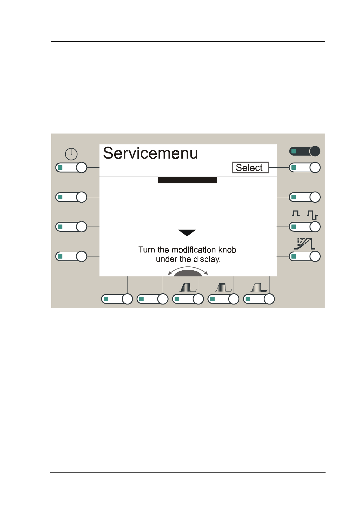
4.1 The Service Menu
The software of the device contains a service menu which makes it possible to check parts of the
device with regard to their correct function. The usage of the service menu is similar to that of the
user menu.
Menü
Keyboard
FIX
CV/CC
Adjustment knobs
Display
Battery
Speaker
Interface
Vacuum
+ / -
/
Basis
autom
TR
Figure
Operating instructions:
1. Simultaneous pressing of the current
2. Switch on the device through the mains switch at the back.
3. When the unit is ready, a sequence of confirmation beeps will be sounded. You can release the
4. You can move the scroll bar with the
5. When the scroll bar has reached the end of the 1
6. The required service function is selected by pressing the white
7. Data/entries can be modified with the
8. Entries are confirmed by pressing the white
9. Most of the service functions are executed either automatically or a detailed user guidance appears
1: First page of the Service menu
keys CP, UR
offered, see Figure 2.
on the display of the device.
and HV now and the service menu will be displayed (see above figure).
type keys CP, UR
Modification knob
Modification knob
st
page of service menu, further functions will be
Softkey [select]
[select]
[select][select]
HV,
and
.
.
and keep them pressed.
Softkey [select]
.
[select].
[select][select]
gbo Medizintechnik AG 2004 Version 1.4
Current Stimulation Devices 9xx
13
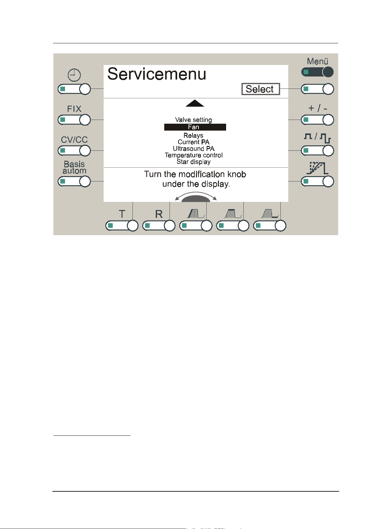
Figure 2: Second page of the service menu
The functions of the service menu are described in the following chapters:
1. Keyboard
2. Adjustment knobs
3. Display
4. Battery
5. Speaker
6. Interface
7. Vacuum
8. Valve setting
9. Fan
10. Relays
11. Current PA
12. ultrasound PA
13. temperature control
14. star display
4.1.1 Keyboard
Call from the service menu:
1. Move the scroll bar to Keyboard.
2. Press the white
gbo Medizintechnik AG 2004 Version 1.4
Softkey [select]
[select].
[select][select]

Current Stimulation Devices 9xx
14
Functional sequence: Proceed as indicated on the display.
1. Please press key, when a key has been pressed, then its designation will appear on the
display and the corresponding LED will be switched on.
2. When all keys have been pressed once and if everything is OK, press the white
[Escape]
[Escape]
[Escape][Escape]
. It returns to the service menu.
Softkey
OK: all keys have been correctly confirmed.
Failure analysis: One key has not been correctly confirmed.
Source of failure: main board or membrane keyboard
Failure correction: replace the main board or membrane keyboard.
4.1.2 Adjustment knobs
Call from the service menu:
1. Move the scroll bar to Adjustment knobs.
2. Press the white
Softkey [select]
[select].
[select][select]
Functional sequence: Proceed as indicated on the display.
1. Turn modification knob
Turn modification knob, turn right, the number on the „right“
Turn modification knobTurn modification knob
2. Turn modification knob
Turn modification knob, turn left, the number on the „left“
Turn modification knobTurn modification knob
3. Turn intensity knob
Turn intensity knob, turn right, the number on the „right“
Turn intensity knobTurn intensity knob
4. Turn intensity knob
Turn intensity knob, turn left, the number on the „left“
Turn intensity knobTurn intensity knob
5. Press the white
Softkey [cancel]
[cancel]
[cancel][cancel]
. It will return to the service menu.
„right“ must increase.
„right“„right“
„left“ must increase.
„left“„left“
„right“ must increase.
„right“„right“
„left“ must increase.
„left“„left“
OK: the above mentioned sequence is progressing correctly.
Failure analysis: Incremental encoders do not function correctly, or loose/weak knobs.
Source of failure: main board or knob/encoder
Failure correction: replace the main board, incremental encoder or knob.
4.1.3 Display
Call from the service menu:
1. Move the scroll bar to DISPLAY.
2. Press the white
gbo Medizintechnik AG 2004 Version 1.4
Softkey [select]
[select].
[select][select]

Current Stimulation Devices 9xx
Functional sequence:
1. The electrical stimulus device is executing the display test.
2. During the test run it has to be visually checked, if all pixels are displayed correctly.
3. The contrast is switched from minimal to maximal in 14 steps.
4. It returns to the service menu.
OK: all display pixel are visually displayed in a correct way.
Failure analysis:
∗ Pixels appear faulty.
Source of error: display
Failure correction: replace the display.
∗ The contrast does not change.
Source of error: VGA module
Failure correction: replace the VGA module.
15
4.1.4 Battery
Call from the service menu:
1. Move the scroll bar to Battery.
2. Press the white
Softkey [select]
[select]
[select][select]
.
Functional sequence:
1. The electrical stimulus device is executing the battery test. During the battery test, the battery is
briefly loaded in order to determine its capacity. The following message appears:
2. Battery is being tested ...
3. Then the message Battery OK or Battery not OK appears.
4. Press the white
Softkey [Escape]
[Escape]
[Escape][Escape]
. It returns to the Service menu.
OK: Battery OK!
Failure analysis: Battery not OK, the battery (order number 007-4-4015) has to be replaced as
soon as possible.
Attention
During the replacement of the battery it is necessary that the electrical stimulus device
is switched on, in order not to lose the data of the battery buffered RAM disk.
gbo Medizintechnik AG 2004 Version 1.4

Current Stimulation Devices 9xx
16
4.1.5 Speaker
Call from the service menu:
1. Move the scroll bar to Speaker.
2. Press the white
Functional sequence:
1. The device is executing the Speaker test.
2. During the test run is has to be acoustically checked, whether the loudspeaker is functioning
properly.
∗ Test: sound volume 1-15 (step size: 1)
∗ Test: sound frequency in Hz 300- 1500 (step size: 100)
∗ Test: gong
3. It returns to the service menu.
OK: the test run sounds acoustically correct.
Failure analysis:
Softkey [select]
[select].
[select][select]
∗ Volume regulator does not work.
∗ Speaker does not work.
Source of failure: main board
Failure correction: replace the main board.
∗ Gong does not work.
Source of failure: bus board
Failure correction: replace the bus board.
4.1.6 Interface
As a short-circuit plug, a 9 pole Sub-D-socket with the
indicated assignment must be used.
Figure 3: short-circuit plug
Call from the service menu:
1. Move the scroll bar to Interface.
2. Press the white
3. Put the short-circuit plug onto the serial interface!
Softkey [select]
[select].
[select][select]
gbo Medizintechnik AG 2004 Version 1.4

Current Stimulation Devices 9xx
17
Functional sequence:
1. The electrical stimulus device is executing the interface test.
2. The message Interface OK or Interface not OK or Transmission error
appears.
3. It returns to the service menu.
Possible error messages/sources of failures:
∗ Plug the short-circuit plug: The short-circuit plug has been forgotten; first plug it
onto the serial interface and then call the function again.
OK: interface test OK.
Failure analysis: interface test not OK.
Source of failure: main board or bus board
Failure correction: replace the main board or bus board.
4.1.7 Vacuum
Call from the service menu:
1. Move the scroll bar to Vacuum.
2. Press the white
Functional sequence:
1. The electrical stimulus device is executing the vacuum test.
∗ Vacuum intensity: 0 - 100 % (step size :10 %)
∗ Pulse rate per minute: 60 - 0 (step size: 30)
2. It returns to the service menu.
OK: test is progressing correctly.
Failure analysis:
∗ Pump does not work.
Source of failure: bus board, relay board, pump or transformer
Failure correction: replace the corresponding component.
∗ There is no suction massage (frequency = 0).
Source of failure: bus board or vacuum magnet
Failure correction: replace the bus board or vacuum magnet.
Softkey [select]
[select]
[select][select]
.
gbo Medizintechnik AG 2004 Version 1.4

Current Stimulation Devices 9xx
18
4.1.8 Valve setting
This function serves for the factory setting of the basic valve characteristic. Do not execute this
function because the factory settings are already reset by calling this function only.
The value determined during the factory setting is given in the test protocol of each unit. If the valve
value has been (erroneously) overwritten, please restore the basic value according to the units test
protocol. The value can be entered with the modification knob after executing this function.
4.1.9 Fan
Call from the service menu:
1. Move the scroll bar to Fan.
2. Press the white
Functional sequence:
Softkey [select]
[select]
[select][select]
.
1. The device is executing the fan test.
2. Fan step 7, 3, 1
3. It returns to the service menu.
OK: test is progressing correctly.
Failure analysis: fan does not work or the step does not change.
Source of failure: bus board or fan
Failure correction: replace the bus board or fan.
4.1.10 Relays
Call from the service menu:
1. Move the scroll bar to Relays.
2. Press the white
Functional sequence:
Softkey [select]
[select]
[select][select]
.
1. The electrical stimulus device is executing the relay test.
2. During the test, all relays are tested subsequently. Herewith each relay is switched on and off five
times.
3. It returns to the service menu.
OK: all relays work correctly.
Failure analysis: One relay is faulty.
gbo Medizintechnik AG 2004 Version 1.4

Current Stimulation Devices 9xx
19
∗ Patient relay is not operating.
Source of failure: plug board
Failure correction: replace the plug board.
∗ Only in case of STEREODYNATOR 928: Endogenous/exogenous relay is not operating.
Source of failure: bus board
Failure correction: replace the bus board.
4.1.11 Current PA
Call from the service menu:
1. Move the scroll bar to current PA.
2. Press the white
Functional sequence:
1. The current stimulation device is executing the test of the current power amplifier.
2. Test of current PA active, then the message current PA OK or current PA
Not OK appears.
3. It returns to the service menu.
Softkey [select]
[select]
[select][select]
.
OK: current PA OK.
Failure analysis: current PA not OK. Replace the respective output transformer.
4.1.12 Ultrasound PA
Call from the service menu:
1. Move the scroll bar to ultrasound PA.
2. Press the white
Functional sequence:
1. Connect the ultrasound dummy.
2. Press the
3. Coupling voltage: -N
Nominal data: 0 +/- 10
4. Press the
5. Head correction: -N
Nominal data: 0 +/- 10
6. Press the
7. actual data: -N
Nominal data: 0 +/- 10
8. Press the white
Softkey [select]
Sono key
Sono key
Sono key.
.
.
Softkey [Escape]
[select].
[select][select]
[Escape]. It returns to the service menu.
[Escape][Escape]
gbo Medizintechnik AG 2004 Version 1.4

Current Stimulation Devices 9xx
20
OK: the values of the ultrasound PA are within the nominal range.
Failure analysis: the values of the ultrasound output transformer are not within the nominal. Replace
or calibrate the ultrasound PA.
4.1.13 Temperature control
Call from the service menu:
1. Move the scroll bar to Temperature control.
2. Press the white
Functional sequence:
1. The electrical stimulus device is measuring the temperatures of the:
transformer: NN °C
current PA 1: NN °C
current PA 2: NN °C (only for STEREODYNATOR 928)
current PA 3: NN °C (only for STEREODYNATOR 928)
ultrasound PA: NN °C
2. Press the white Softkey [Escape]
Softkey [select]
[select] .
[select][select]
[Escape]. It returns to the service menu.
[Escape][Escape]
OK: the temperature values are within sensible limits (depending on the operating time and the
ambient temperature).
Failure analysis:
∗ The temperature values of the output transformers are not within a sensible range, replace the
respective output transformer.
∗ The transformer temperature is not within a sensible range.
Source of failure: bus board or transformer
Failure correction: replace the bus board or transformer.
4.1.14 Star display (only in case of STEREODYNATOR 928)
Call from the service menu:
1. Move the scroll bar to Star display.
2. Press the white
Functional sequence:
Softkey [select]
[select]
[select][select]
.
1. The device is executing the test of the star display.
2. During the test it must visually checked to make sure all LEDs of the star display are being tested
correctly.
gbo Medizintechnik AG 2004 Version 1.4

Current Stimulation Devices 9xx
3. It returns to the service menu.
OK: all LEDs are displayed visually correct.
Failure analysis: LED is not lit up, replace the star display.
21
4.2 Filing of new Firmware - Version
The current stimulation device offers the possibility of loading and filing new software through the
serial interface. Therefore a PC which is connected to the device through a serial interface is required.
In addition, the software RZFLASH.EXE needs the file flprog.exe and update.bin in the same
directory.
Procedure:
1. Simultaneously press the current type keys Micro, T/R and Tens Burst and keep them pressed.
2. Switch on the device through the mains switch at the back.
3. Release the
4. The electrical stimulus device now waits for the transmission of the files.
Key line
only when the device is ready for operation and the tone has sounded.
Notice
!!
5. Call-up the PC program RZFLASH, select an interface and set the transmission speed to
19200 Baud.
6. Start transmission, this action can be observed on the display of the current stimulation device
and on the connected PC monitor.
You can exit this status only by switching off and on again!
Attention
The voltage supply of the device should be interrupted by no means during FLASH
programming! During the operation, you have no possibility of intervention!
Procedure of FLASH - programming:
∗ The service program for the FLASH programming itself is being transmitted.
∗ The new Firmware is being transmitted (both will be stored on the RAMDISK of the current
stimulation device).
∗ A temporary file is being created which should restart the procedure if unexpected errors appear
and the Firmware has not yet been replaced.
∗ FLASH programming is being started: PROM will now be blockwise deleted and newly
programmed
∗ After the successful programming, the current stimulation device is restarted automatically.
!!
Notice
gbo Medizintechnik AG 2004 Version 1.4
briefly check the function of the device.

Current Stimulation Devices 9xx
Attention
If for some reason FLASH programming was interrupted, the device has to be
restarted !!
If the device does not show any function after the restart, then the Flash-EPROM
must be replaced physically!
22
gbo Medizintechnik AG 2004 Version 1.4

Current Stimulation Devices 9xx
5 Disassembly - assembly flow diagram
23
Attention
before you open the device, disconnect the mains plug!!
figure 4: Disassembly – assembly flow diagram
gbo Medizintechnik AG 2004 Version 1.4

Current Stimulation Devices 9xx
6 Safety check
6.1 Ground conductor check
After assembly of the device, a check of the ground conductor must be performed in accordance with
the test protocol (see appendix).
6.2 Leakage current check
If a printed circuit board is being replaced, the leakage current must also be measured; see the test
protocol in the appendix.
24
gbo Medizintechnik AG 2004 Version 1.4

Current Stimulation Devices 9xx
25
7 Spare parts list
component: order number:
Adjustment knob 014-5-0001-E
Battery 007-4-4015-E
Bus board for Universal-NEUROTON 926, Therapie-NEUROTON 927,
SONODYNATOR 934
014-1-0014-E
Bus board for STEREODYNATOR 928
014-1-0003-E
Current power amplifier 014-1-0026-E
Display 005-4-2020-E
DSP module, complete 014-1-0008-E
EX module 013-1-0004-E
Incremental encoder for modification and intensity control 007-2-7030-E
Main board 014-1-0001-E
Mains filter 007-4-5015-E
Power supply 014-1-0004-E
Pump with mounting racket and filter 014-1-0042-E
Relay printed circuit board 014-1-0020-E
Side part complete, with ultrasound 014-1-0010-E
Side part complete, without ultrasound 014-1-0017-E
Star display 014-3-0001-E
Transformer 014-4-4003-E
Ultrasound dummy 014-0-0005
Ultrasound power amplifier 014-1-0009-E
Vacuum magnet 014-4-0006-E
Fan 014-1-0035-E
VGA module 014-1-0002-E
gbo Medizintechnik AG 2004 Version 1.4

Current Stimulation Devices 9xx
8 Circuit diagrams
Figure Denomination Version
1 RS-9XX-Block diagram
2 RS-9XX-Bus component plan 1.1
3 RS-9XX-Bus block diagram Index 2
4 RS-9XX-Bus amplifier bus Index 2
5 RS-9XX-Bus output circuit Index 2
6 RS-9XX-Bus vacuum control Index 2
7 RS-9XX-Bus DSP module component plan 2.0
8 RS-9XX-DSP module Index 2
9 RS-9XX-Main board component plan 3.1
10 RS-9XX-Main board block diagram Index 3
11 RS-9XX-Main board Bus I/O Index 3
12 RS-9XX-Main board 386 EX module Index 3
13 RS-9XX-Main board VGA controller Index 3
14 RS-9XX-Main board S-RAM Index 3
15 RS-9XX-Main board Front panel I/O Index 3
16 RS-9XX-Main board Sound Index 3
17 RS-9XX-Main board Chip select Index 3
18 RS-9XX-Main board Battery power Index 3
19 RS-9XX-Main board incremental encoder Index 3
20 RS-9XX-Power supply component plan 3.0
21 RS-9XX- Power supply Index 2
22 RS-9XX-Patient plug module component plan 2.0
23 RS-9XX Patient plug module 1/2 Index 2
24 RS-9XX Patient plug module 2/2 Index 2
25 RS-9XX Relay module component plan
26 RS-9XX Relay module
27 RS-9XX-Current power amplifier component plan 7.0
28 RS-9XX- Current power amplifier Index 7
29 RS-9XX-Ultrasound power amplifier component plan 2.0
30 RS-9XX-Ultrasound power amplifier Index 2
31 RS-9XX-VGA controller component plan 2.0
32 RS-9XX-VGA controller Index 3
26
gbo Medizintechnik AG 2004 Version 1.4

Current Stimulation Devices 9xx
27
DSP
Bus
Connector I
Signal
Digital
Decoder
Processor
Driver and
Connectors
PAT-
Relay 1 +
Control
PAT-
Relay 2 +
Control
Connector II
PAT-
Relay 3 +
Control
Connector III
Block Diagram
Stimulators 9XX
Last Modification
Comb
Relay
Endogen/Exogen
SUB-D-
Connector
Encoder
Serial
V.24-Driver
DSP-Data and Control
Control
Speaker
Gong
Signal
Current
Power
Amplifier 1
Transducer
Current
Power
Amplifier 2
Transducer
Current
Power
Ultrasound
Power Amplifier
Fan
Control
Amplifier 3
Vacuum
Control
Relay
Control
Fan
Va cu u m
Control
Relay
Pump
320 x 240
¼ VGA-Display
VGA
Controller
Test
Power
Battery
Mainboard
Vol u me
Control
Speaker and
Chipselect SRAM
I/O
Data
Control
Adress
J5J6
J2
Reset Clock
Chipset
Star
Display
J1
CPU
EX-Module
Battery
LED
Control
Control
Keyboard
Encoder
Modification
J4
D-RAM
Encoder
Intensity
J3
Flash-Prom
Control
Data
Adress
8 x 8
LED-
Matrix
8 x 8
Matrix
Keyboard
VGA-Module
Contrast Control
24 V
24 V
-15 V
Mains
Filter
95 V
215 V
+5 V
+15 V
110 °C
Power Supply
Figure 1
gbo Medizintechnik AG 2004 Version 1.4

Current Stimulation Devices 9xx
28
Figure 2
gbo Medizintechnik AG 2004 Version 1.4

Current Stimulation Devices 9xx
29
Figure 3
gbo Medizintechnik AG 2004 Version 1.4

Current Stimulation Devices 9xx
30
Figure 4
gbo Medizintechnik AG 2004 Version 1.4

Current Stimulation Devices 9xx
31
Figure 5
gbo Medizintechnik AG 2004 Version 1.4

Current Stimulation Devices 9xx
32
Figure 6
gbo Medizintechnik AG 2004 Version 1.4

Current Stimulation Devices 9xx
33
Figure 7
gbo Medizintechnik AG 2004 Version 1.4

Current Stimulation Devices 9xx
34
Figure 8
gbo Medizintechnik AG 2004 Version 1.4

Current Stimulation Devices 9xx
35
Figure 9
gbo Medizintechnik AG 2004 Version 1.4

Current Stimulation Devices 9xx
36
Figure 10
gbo Medizintechnik AG 2004 Version 1.4

Current Stimulation Devices 9xx
37
Figure 11
gbo Medizintechnik AG 2004 Version 1.4

Current Stimulation Devices 9xx
38
Figure 12
gbo Medizintechnik AG 2004 Version 1.4

Current Stimulation Devices 9xx
39
Figure 13
gbo Medizintechnik AG 2004 Version 1.4

Current Stimulation Devices 9xx
40
Figure 14
gbo Medizintechnik AG 2004 Version 1.4

Current Stimulation Devices 9xx
41
Figure 15
gbo Medizintechnik AG 2004 Version 1.4

Current Stimulation Devices 9xx
42
Figure 16
gbo Medizintechnik AG 2004 Version 1.4

Current Stimulation Devices 9xx
43
Figure 17
gbo Medizintechnik AG 2004 Version 1.4

Current Stimulation Devices 9xx
44
Figure 18
gbo Medizintechnik AG 2004 Version 1.4

Current Stimulation Devices 9xx
45
Figure 19
gbo Medizintechnik AG 2004 Version 1.4

Current Stimulation Devices 9xx
46
Figure 20
gbo Medizintechnik AG 2004 Version 1.4

Current Stimulation Devices 9xx
47
Figure 21
gbo Medizintechnik AG 2004 Version 1.4

Current Stimulation Devices 9xx
48
Figure 22
gbo Medizintechnik AG 2004 Version 1.4

Current Stimulation Devices 9xx
49
Figure 23
gbo Medizintechnik AG 2004 Version 1.4

Current Stimulation Devices 9xx
50
Figure 24
gbo Medizintechnik AG 2004 Version 1.4

Current Stimulation Devices 9xx
Figure 25
51
gbo Medizintechnik AG 2004 Version 1.4

Current Stimulation Devices 9xx
52
Figure 26
gbo Medizintechnik AG 2004 Version 1.4

Current Stimulation Devices 9xx
53
Figure 27
gbo Medizintechnik AG 2004 Version 1.4

Current Stimulation Devices 9xx
54
Figure 28
gbo Medizintechnik AG 2004 Version 1.4

Current Stimulation Devices 9xx
55
Figure 29
gbo Medizintechnik AG 2004 Version 1.4

Current Stimulation Devices 9xx
56
Figure 30
gbo Medizintechnik AG 2004 Version 1.4

Current Stimulation Devices 9xx
Figure 31
57
gbo Medizintechnik AG 2004 Version 1.4

Current Stimulation Devices 9xx
58
Figure 32
gbo Medizintechnik AG 2004 Version 1.4

Current Stimulation Devices 9xx
Correction sheet
gbo Medizintechnik AG
- Documentation -
Kleiststraße 6
64668 Rimbach
Please work on the faults and/or suggestions to present documentation:
Page Line Faulty text Correct text
59
(If needed, please attach an additional sheet.)
Address:
Art.-No. 014-7-0027
gbo Medizintechnik AG 2004 Version 1.4
 Loading...