

Page 1
GBC ProTrim 45 / 63
©2006. General Binding Corporation. All rights
reserved
Page 2

©2006. General Binding Corporation. All rights
reserved
Table of Contents
• Specifications
• Included parts and tools
• Assembly
•
Operation Instructions
Specifications
Dimensions
Box:
Unit:
ProTrim 63
ProTrim 45 12.5” x 23.75” x 59”
ProTrim 63 12.5” x 23.75” x 76.5”
ProTrim 45
H x W x L
43.25” x 15.75” x 57”
43.25” x 15.75” x 78.75”
Cutting Specifications:
Maximum Cut Length: ProTrim 45 = 45”
ProTrim 63 = 63”
2
Page 3
Inc
luded Parts and Tools
©2006. General Binding Corporation. All rights
reserved
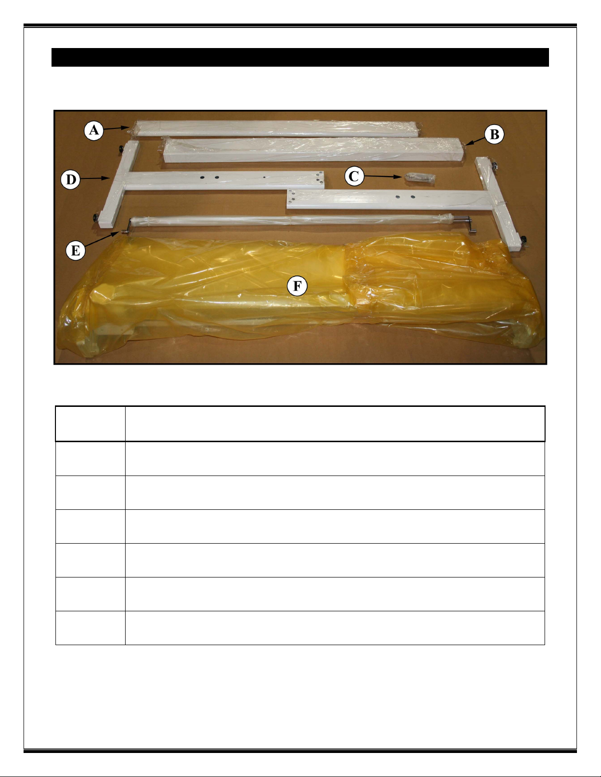
Item Description
A
B
C
D
E
F
Mid cross member (Distinguishable by rounded edges)
Upper cross member (Distinguishable by squared edges)
Hardware Pack
Legs ( Left & Right)
Waste Curtain
Trimmer assembly
3
Page 4

Included Parts and Tools
©2006. General Binding Corporation. All rights
reserved
Item
A
B
C
D
E
Description
Bolts, Qty 4. ( Used to secure the legs to the upper cross member)
Bolts, Qty 2, ( Used to secure waste curtain shaft to stand)
Bolts, Qty 4. ( Used to secure the mid cross member to the legs)
Bolts, Qty 4. ( Used to secure the trimmer assembly to the stand)
Hex Tool ( Includes one of the following sizes 6mm, 5mm, & 4mm)
4
Page 5

Assembly
©2006. General Binding Corporation. All rights
reserved
Begin by finding the two legs
and the upper cross member.
The legs must be oriented
correctly so that the larger holes
are on the outside of the unit.
The smaller hole must be facing
toward the inside of the unit.
Lay the upper cross member on
the floor, then align one of the
legs with the end of the cross
member so the bolts can be
inserted through the leg and
into the upper cross member.
Use the bolts identified as ( A )
in the hardware section to
secure the leg to the upper cross
member. The 5mm Hex tool
should be used on these bolts.
Once completed, repeat this
step on the other leg.
5
Page 6

Assembly
©2006. General Binding Corporation. All rights
reserved
Place the stand on its feet.
Attach the mid cross member to
the stand with the bolts
identified as “ C “ in the
hardware section of this
manual. Use the 6mm Hex tool
for these bolts.
The stand should now be
completed. Two people are
required for the next step. With
one person on each side of the
trimmer assembly, carefully
pick it up while keeping it level
to prevent the cutter head
assembly from moving. Place
the trimmer assembly on top of
the stand.
6
Page 7

Assembly
©2006. General Binding Corporation. All rights
reserved
Use the bolts identified as “ D “
in the hardware section to
secure the trimmer assembly to
the top of the stand. Use the
6mm Hex tool for these bolts.
Remove the wire ties from the
waste curtain, and then install
the waste curtain in the rear of
the trimmer as shown in the
photo.
7
Page 8

Assembly
©2006. General Binding Corporation. All rights
reserved
Attach the other waste curtain
support bar to the stand of the
trimmer with the bolts
identified as “ B “earlier in this
manual.
The assembly of the trimmer is
now complete.
8
Page 9

Operation
©2006. General Binding Corporation. All rights
reserved
The GBC ProTrim 45 and
ProTrim 63 were designed with
ease of operation in mind.
The steps for proper operation
are as follows:
1.) Move the cutter head all the
way to the right or left side of
the trimmer. (This is required
because the paper clamp
applies slight pressure to the
print when the cutter head is
not all the way to one side of
the unit.)
2.) Insert the print to be
trimmed.
3.) Adjust the edge guide as
necessary to aid in squaring the
print.
4.) Use the paper clamp as an
aid to determine where the cut
will be made in the print.
Support the print with one
hand; use your other hand to
slide the cutter head across the
trimmer to make the cut.
5.) Remove the trimmed pieces
from the waste curtain as
necessary.
9
Page 10

©2006. General Binding Corporation. All rights
reserved
10
 Loading...