

Page 1
ProCut Paper Cutter
Model 20P
INSTALLATION &
OPERATION MANUAL
Document Number: 1729247 Rev. A
Do not duplicate without written permission from ACCO Brands.
Store this instruction manual in a safe place for future reference.
Page 2

ProCut 20P – Installation and Operating Instructions
Page i
ACCO Brands reserves the right to make changes
to this publication and to the products described in
it without notice. All specications and information
concerning products are subject to change without
notice. Reference in this publication to information or
products protected by copyright or patent does not
convey any license under the rights of ACCO Brands
or others. ACCO Brands assumes no liability arising
from infringements of patents or any other rights of third
parties.
This publication is copyrighted © 2015 by ACCO Brands.
All rights reserved.
© 2015 ACCO Bran ds. All rights res erved. ACCO® is a registered tradem ark of
ACCO Bran ds. GBC® is a registered trad emark of General B inding Co rporation.
1729247 Rev. A 2015/03
ACCO Brands Canada Inc.
7381 Bramalea Road
Mississauga ON L5S1C4
800.263.1063
www.gbccanada.com
ACCO Mexicana
Neptuno 43, Fraccionamiento Nueva Industrial Vallejo
México 07 700 D.F.
Delagación Gustavo A.
Madero
(55) 1500 5778
www.accomexico.mx
ACCO Brands
4 Corporate Drive
Lake Zurich, IL 60047
In USA call 800.772.9281
www.gbcconnect.com
IntroductIon
The equipment is designed to provide you with improved
productivity, versatility, and quality.
Note: Depending on the model and its version, the
photos in this manual may not look like your machine.
However, the components and functions are the same.
Features
• Intuitive user LCD display
• Programmable for up to 80 programs with up to
99 steps
• Electric blade, clamp and back gauge
BeneFIts
• LED optical cut line ensures accuracy
• Reset button recalibrates machine for accuracy
• Full programmability increases speed of cutting
saFety
• Two handed cut and clamp activation buttons
• Mechanical safety latch and light curtain safety
shield
• Push-out feature moves media forward after the
cut is complete
Page 3

Page ii
ProCut 20P – Installation and Operating Instructions
Introduction ................................................................ i
Features ................................................................ i
Benets ................................................................. i
Safety .................................................................... i
1. Safety
Cautions ................................................................ 1-2
General .................................................................. 1-2
Electrical ................................................................ 1-2
GBC Technical Service ......................................... 1-2
2. Warranty
Limited One Year Parts, 90 Days Labor Warranty;
USA, Mexico, and Canada .................................... 2-1
3. Specications
FCC Class A Notice .............................................. 3-2
Canada Class A Notice - Avis Canada, Classe A . 3-2
Modications ......................................................... 3-2
4. Installation
GBC Technical Service ......................................... 4-1
Prior to Installation ................................................. 4-1
Installation ............................................................. 4-1
Location ............................................................ 4-2
5. Feature Guide
Infrared Safety Walls ............................................. 5-1
Jogging Aid ............................................................ 5-1
Back Gauge ........................................................... 5-1
The Clamp & Cutting Blade ................................... 5-1
Cut Stick ................................................................ 5-1
Control Panel ......................................................... 5-2
A. LCD Display .................................................. 5-2
B. Keypad .......................................................... 5-2
C. Operation Buttons ........................................5-3
E. Blade Adjustment.......................................... 5-3
6. Operation
Powering Up the Machine ..................................... 6-1
Operating the Machine .......................................... 6-1
Manual Operation ............................................. 6-1
Programming the Machine .................................... 6-1
Entering a Program ........................................... 6-1
7. Operator Maintenance
Caring for the ProCut 20P ......................................7-1
Cleaning The Paper Cutter ................................7-1
Cut Stick Rotation and Replacement .................7-1
Blade Replacement ............................................7-1
8. Function Values
Changing Function Values .................................... 8-2
taBle oF contents
Page 4

ProCut 20P – Installation and Operating Instructions
Page iii
Page 5
Page 1-1
ProCut 20P – Installation and Operating Instructions
Your safety, as well as the safety of others, is
important. Before you install or use the machine,
read and follow all the safety notices carefully in
this chapter. In this instruction manual, and on the
machine, you will nd important safety notices
related to the use of the product. Observe all the
safety information provided.
Read all of the instructions and save these
instructions for further use. Also make sure you have
been fully trained before operating.
The safety alert symbol precedes each
safety notice in this manual. The symbol indicates a
potential personal safety hazard to you or others.
This safety alert symbol indicates a potential
electrical shock. It warns you not to open the
machine and expose yourself to hazardous voltage.
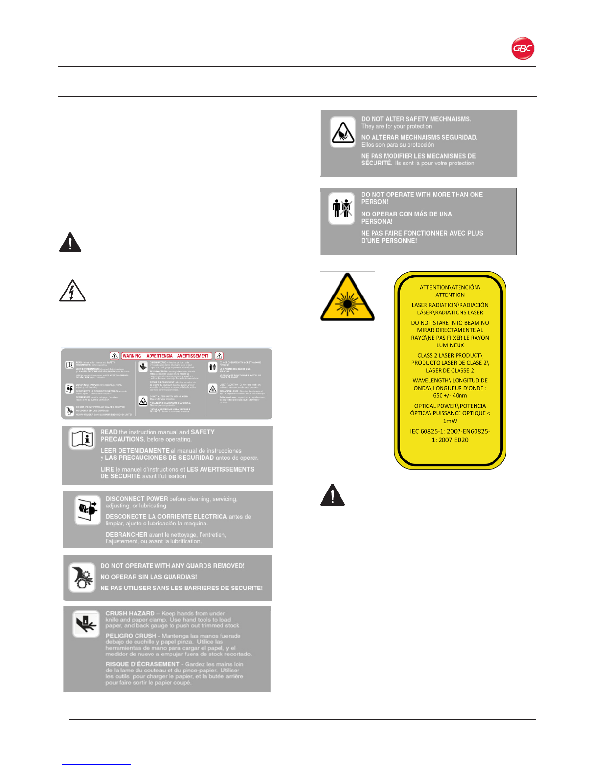
The following warnings are found on the equipment.
WarnInGs
• Do not attempt to service or repair the
machine.
• Do not open the machine. There are no
serviceable parts inside. Refer service to
qualified service personnel.
• Do not attempt to modify this equipment.
• Do not connect to an electrical supply or
attempt to operate until you have completely
read these instructions. Maintain these
instructions in a convenient location for future
reference.
• Entrapment hazard. Do not operate when
alone. More than one person is required to be
in the area when operating the machine.
• To guard against injury, the general safety
precautions must be observed when installing
and using the machine.
1. saFety
Page 6

ProCut 20P – Installation and Operating Instructions
Page 1-2
WarnInGs (cont’d)
• Consider the work area. A cluttered work area
can lead to accidents. The machine must be
placed on a sturdy level floor surface. Allow
sufficient access to the front, back, and sides.
Keep the work area well lit.
• Plastic bags must be kept out of reach of
children.
Failure to observe these warnings could result in
severe personal injury or death.
cautIons
Caution indicates a hazardous situation which, if not
avoided, could result in minor or moderate injury or
cause damage to the machine.
General
• Keep ngers, hands clothing, jewelry, and long
hair away from the front of the Working Table,
Clamp, and Cutting Blade.
• Use only sufficiently stable and compatible
stands. Make certain the equipment is installed
securely and cannot fall down.
• Do not use the machine for other than its
intended purpose.
• Avoid quick stops, excessive force and uneven
floor surfaces when moving the machine.
• The cutter and stand are separate components.
The cutter and stand will need to be lifted and
moved separately.
• Do not defeat or remove electrical and
mechanical safety equipment such as interlocks,
shields and guards.
• Do not insert objects unsuitable for the purpose
of this machine or expose the equipment to
liquids.
• The cabinet should remain locked at all times
and only be opened by approved personnel.
• Do not store flammable items in the cabinet.
Before you operate this machine, it is important that
you read and understand the entire contents of these
instructions.
electrIcal
The machine should be connected only to a source
of power as indicated in these instructions and on the
nomenclature plate located on the side of the machine.
Contact an electrician should the attachment plug
provided not match the receptacles at your location.
After plugging in, check that the power cord does not
create a tripping hazard.
WARNING: Do not attempt to service or repair.
Failure to observe this warning could result severe
personal injury or death.
Disconnect the plug from the receptacle and contact
your dealer or distributor, or GBC Technical Service at
1-800-723-4000, when one or more of the following has
occurred.
• The power supply cord or attachment plug is
damaged.
• Liquid has been spilled into the machine.
• The machine is malfunctioning.
• The machine does not operate as described in
these instructions.
Opening the machine exposes you to hazardous
voltage, which can seriously hurt or kill you.
There are no user serviceable parts inside. Refer
service to qualied service technician.
CAUTION: The receptacle must be located near the
equipment and must be easily accessible.
Disconnect the attachment plug from the receptacle to
which it is connected and keep the power supply cord in
your possession when moving.
GBc technIcal servIce
To order replacement accessories, service, parts, or
an Equipment Maintenance Agreement, please contact
GBC Technical Service and Support at:
unIted states
ACCO Brands
GBC Technical Service and Support
4 Corporate Drive
Lake Zurich, IL 60047-8997
www.gbcconnect.com
1-800-723-4000
canada
Ontario and Quebec – 1-800-268-3310
All other Provinces – 1-800-268-3447
Local 905-595-3100
Callcentre@GBCCanada.com
MexIco
(55) 1500 5778
Lada SIN costo: 01 800 759 6825
serviciotecnico@acco.com.mx
Page 7

Page 2-1
ProCut 20P – Installation and Operating Instructions
2. Warranty
lIMIted one year Parts, 90 days
laBor Warranty; usa, MexIco,
and canada
ACCO Brands USA LLC, ACCO Brands, 4 Corporate
Drive, Lake Zurich, IL 60047 (in Mexico, ACCO
Brands Mexicana,Neptuno 43, Fraccionamiento Nueva
Industrial Vallejo México 07700 D.F. México), (in
Canada, ACCO Brands Canada Inc., 7381 Bramalea
Road, Mississauga ON L5S1C4) (each, respectively,
“ACCO Brands”) warrants to the original purchaser
that this ACCO Brands product is free from defects
in workmanship and material under normal use and
service for a period of: one (1) year for parts and ninety
and (90) days for labor after purchase.
ACCO Brands’ obligation under this warranty is limited
to replacement or repair, at ACCO Brands’ option, of
any warranted part found defective by ACCO Brands
without charge for material or labor. Any replacement,
at ACCO Brands’ option, may be the same product
or a substantially similar product that may contain
remanufactured or refurbished parts. This warranty
shall be void in the following circumstances:
(i) if the product has been improperly installed or
misused,
(ii) if the product has been damaged by negligence or
accident, or
(iii) if the product has been altered by anyone other
than ACCO Brands or ACCO Brands’ authorized
agents.
Without limiting the generality of the previous
paragraph, ACCO Brands’ obligation under this limited
warranty does not include:
(a) damage caused to the rollers by knives, razors,
or other sharp tools; by any foreign objects falling
into the working area of the laminator; or by cleaning
the laminator with solutions or materials that harm its
surfaces;
(b) damage caused by adhesives; nor
(c) damage caused by lifting, tilting or attempting to
position the laminator other than rolling it on its castors
across even surfaces. For warranty execution, please
contact ACCO Brands at:
800-723-4000 or www.gbcconnect.com in the USA
800-263-1063 or www.gbccanada.com in Canada
(55) 1500 5578 or www.accomexico.mx in Mexico
TO THE EXTENT ALLOWED BY APPLICABLE
LAW, THIS WARRANTY IS IN LIEU OF ALL OTHER
EXPRESSED WARRANTIES. REPRESENTATIONS
OR PROMISES INCONSISTENT WITH OR
IN ADDITION TO THIS WARRANTY ARE
UNAUTHORIZED AND SHALL NOT BE BINDING ON
ACCO BRANDS. TO THE EXTENT PERMITTED BY
APPLICABLE LAWS, ANY IMPLIED WARRANTIES
(IF APPLICABLE) ARE LIMITED IN DURATION
TO THE DURATION OF THIS WARRANTY.
SOME STATES AND JURISDICTIONS DO NOT
ALLOW LIMITATIONS ON HOW LONG AN
IMPLIED WARRANTY LASTS, SO THE ABOVE
LIMITATION MAY NOT APPLY TO YOU. TO THE
EXTENT PERMITTED BY APPLICABLE LAW, IN
NO EVENT SHALL ACCO BRANDS BE LIABLE
FOR ANY SPECIAL, INCIDENTAL, PUNITIVE,
EXEMPLARY, CONSEQUENTIAL OR SIMILAR
DAMAGES, WHETHER OR NOT FORESEEABLE.
SOME STATES AND JURISDICTIONS DO NOT
ALLOW THE EXCLUSION OR LIMITATION OF
SPECIAL, INCIDENTAL, PUNITIVE, EXEMPLARY,
CONSEQUENTIAL, OR SIMILAR DAMAGES, SO
THE ABOVE EXCLUSION OR LIMITATION MAY NOT
APPLY TO YOU.
FOR CONSUMERS WHO HAVE THE BENEFIT
OF CONSUMER PROTECTION LAWS OR
REGULATIONS IN THEIR JURISDICTION OF
PURCHASE OR, IF DIFFERENT, IN THEIR
JURISDICTION OF RESIDENCE, THE BENEFITS
CONFERRED BY THIS WARRANTY ARE IN
ADDITION TO ALL RIGHTS AND REMEDIES
CONVEYED BY SUCH CONSUMER PROTECTION
LAWS AND REGULATIONS.
To the extent permitted by law, this warranty is not
transferable and will automatically terminate if the
original product purchaser sells or otherwise disposes
of the product.
This warranty gives you specic legal rights. Other
rights, which vary from jurisdiction to jurisdiction, may
exist. In addition some jurisdictions do not allow
(i) the exclusion of certain warranties, (ii) limitations
on how long an implied warranty lasts and/or (iii) the
exclusion or limitation of certain types of costs and/ or
damages, so the above limitations may not apply.
Page 8

ProCut 20P – Installation and Operating Instructions
Page 2-2
Page 9

Page 3-1
ProCut 20P – Installation and Operating Instructions
Model
ProCut 20P
Control
Programmable
Minimum Cut Length
1.19 in. (30 mm)
Maximum Cut Length
20.43 in. (519 mm)
Maximum Cut Thickness
2.5 in. (64 mm)
Maximum Cut Width
20.43 in. (519 mm)
Dimensions:
• Width
• Height
• Depth
• Work Table Height
34.5 in. (876 mm)
52.5 in. (1334 mm)
45.5 in. (1156 mm)
39.5 in. (1003 mm)
Weight
419 lbs. (190 kg).
Electrical Requirements:
• Voltage
• Current
• Power
• Receptacle
208-240V 60 Hz
8A
1400 Wat ts
NEMA 6-15P
Cycle Time
Operating time = 7 seconds
Rest time = 3 seconds
Paper Press Method/Clamp
Automatic
Paper Pusher/Back Gauge
Automatic
3. sPecIFIcatIons
W
i
d
t
h
De
pt
h
Height
Figure 1. ProCut 20P Dimensions
Page 10

ProCut 20P – Installation and Operating Instructions
Page 3-2
Fcc class a notIce
This device complies with Part 15 of the FCC Rules.
Operation is subject to the following two conditions:
• This device may not cause harmful interference.
• This device must accept any interference
received, including interference that may cause
undesired operation.
Note: This equipment has been tested and found to
comply with the limits for a Class A digital device,
pursuant to Part 15 of the FCC rules. These limits are
designed to provide reasonable protection against
harmful interference when the equipment is operated
in a commercial environment. This equipment
generates, uses and can radiate radio frequency
energy and, if not installed and used in accordance
with the instruction manual, may cause harmful
interference to radio communications. Operation
of this equipment in a residential area is likely to
cause harmful interference in which case the user
will be required to correct the interference at his own
expense.
canada class a notIce - avIs
canada, classe a
This Class A digital apparatus complies with Canadian
ICES-003.
Cet appareil numérique de la classe A est conforme à
la norme NMB-003 du Canada.
ModIFIcatIons
Any modications made to this device that are not
approved by ACCO Brands may void the authority
granted to the user by the FCC and/or by Industry
Canada to operate this equipment.
Toutes modications apportées à ce dispositif et non
approuvées par ACCO Brands annuleront le droit
accordé à l’utilisateur par le FCC et/ou par Industrie
Canada de faire fonctionner cet équipement.
Page 11

Page 4-1
ProCut 20P – Installation and Operating Instructions
WARNING: Do not attempt to service or repair
the machine. Failure to observe this warning could
result in severe personal injury or death.
Disconnect the plug from the receptacle and contact
GBC Technical Service when one or more of the
following has occurred.
• The power supply cord or attachment plug is
damaged.
• Liquid has been spilled into the machine.
• The machine is malfunctioning.
• The machine does not operate as described
in these instructions.
GBc technIcal servIce
United States
1-800-723-4000
Canada
Ontario and Quebec – 1-800-268-3310
All other Provinces – 1-800-268-3447
Local 905-595-3100
Mexico
(55) 1500-5778
PrIor to InstallatIon
Inspect the crate and machine for damage. Shipping
damage should be brought to the immediate
attention of the delivering carrier.
WARNING: Do not attempt to move the
machine across anything other than a at, level
surface without trained and qualied riggers. You
can be severely injured or crushed.
The ProCut 20P Series Cutter is a large and heavy
piece of equipment. It is not designed to be tipped
up or tipped sideways in anyway.
Prepare the site:
1. Allow enough room to access all sides of the
machine. Refer to the illustration on the next
page.
2. Ensure the floor is stable and a flat surface
capable of supporting the weight of the machine
and any materials. All four foot pads should be
able to be positioned completely on a level and
smooth surface.
InstallatIon
There are no operator serviceable parts to the
machine other than periodic cleaning. Refer to the
Operator Maintenance chapter.
During installation, observe the safety regulations
applicable for your country.
WARNING: A trained GBC Technician MUST
install the machine for the rst time. Failure to
observe this warning could result in severe bodily
injury or death.
CAUTION: Do not attempt to install the machine
yourself for the rst time. You could damage the
machine.
4. InstallatIon
Page 12

ProCut 20P – Installation and Operating Instructions
Page 4-2
locatIon
The ProCut 20P should be located in a space that allows
adequate room to operate the machine. Allow at least
six inches behind the machine. It is recommended that
a media table be used to stage the sheets to be cut.
A second media table is recommended for nished
material. Keep the working area of the cutter free from
clut ter.
Avoid locating the cutter in a high trafc area. When not
in use, the ProCut 20P can be unplugged.
Operator
Media Table Media Table
6 inches
12 inches
Figure 2. ProCut 20P Location
Page 13

Page 5-1
ProCut 20P – Installation and Operating Instructions
5. Feature GuIde
This chapter identies the main components of the
machine.
InFrared saFety Walls
Figure 3. Infrared Safety Walls
The side walls on the working table contain infrared
sensors which prevent the machine from operating when
the sensors are obstructed. If an obstruction occurs, up
to 65mm above the working table, an alarm sounds and
the cut and clamp functions will not operate.
JoGGInG aId
Figure 4. Jogging Aid
The Jogging Aid is used to register the paper against the
Back Gauge.
Back GauGe
Figure 5. Back Gauge
Sets the proper position for cutting based on the values
entered through the Control Panel. Media is then pushed
against the Back Gauge using the Jogging Aid, to ensure
a straight and accurate cut. Laser Cut Line
Figure 6. Red LED Laser Cut Line
The cut line, as shown in the photo above, is visible
only when the machine is turned ON. The line indicates
where the paper stack will be cut.
the claMP & cuttInG Blade
Figure 7. The Clamp (dark grey) and Cutting Blade
The Clamp activates rst, pressing and holding down the
media to ensure a clean cut. The Cutting Blade then cuts
the stack. The blade should be sharpened or replaced
every 2000 – 3000 cuts based on 20 lb. bond paper.
Cutting Blades can be sharpened multiple times but it
is recommended not to remove more than 8mm off the
blade. The number of times you can sharpen the blade
will depend on the types of media being cut.
cut stIck
Figure 8. Cut Stick (red) and Removal Tool
The Cut Stick provides a clean cut as the Cutting Blade
makes contact with it. The Cut Stick can be rotated to
provide eight cutting surfaces.
Page 14

ProCut 20P – Installation and Operating Instructions
Page 5-2
WARNING: Keep hands and ngers away from
the Clamp and Cutting Blade. Failure to observe
this warning could result in severe personal
injury.
control Panel
In addition to the manual cut settings, the ProCut 20P
can be programmed for in front and behind the blade
cutting. Up to 80 programs, containing 99 steps each,
can be stored for reuse.
The Control Panel includes an LCD display and keypad.
The LCD shows the current and programmed settings of
the cutter and the keypad is used to set up and program
the cutting programs.
a. lcd dIsPlay
The display shows the current settings of the machine.
The values shown can be displayed in millimeters or
inches.
01 00.00
00.00 00.00 00.00
00.00
00.00
00.0000.00
05 06
02
07
03
08
04
x
10.00
5 inch 0716 00
Figure 9. Rendering of LCD Display
claMPInG Force:
Indicates the amount of pressure applied to the media.
The pressure can be set from 1 (highest) to 9 (lowest)
with the default being 5. You must be in the Clamping
Force setting screen to adjust the pressure.
saFety curtaIn alarM:
Indicates whether the alarm buzzer is enabled or disabled.
reBladInG Mode:
Used when changing the blade.
WARNING: Blade removal should only be done
by a GBC Technician. Failure to observe this
warning could result in severe personal injury.
BehInd the Blade:
Cut value is measured from behind the blade to the Back
Gauge.
In Front oF the Blade:
Cut values are measured by the amount of media
the Back Gauge pushes in front of the blade from the
previous cut.
Back GauGe value:
The numeric value displayed is the current position of the
Back Gauge.
ProGraMMInG values:
Displays the programmed cuts entered for each step.
count value:
Provides the total cuts performed during the lifetime of
the machine.
B. keyPad
The keypad is used to:
• Set the cutting size when operating in manual
mode
• Change cutter settings
• Select or create programs
Figure 10. Keypad
Use the numeric keypad to enter the cut values in
manual mode or when entering programs. To add a
decimal, press the decimal button.
When display is in menu mode, the Up and Down arrow
buttons are used to scroll through the menu and to
increase or decrease selected values.
set:
Use the Enter button to access the menu mode. Once
in menu mode, use the numeric buttons to set the value
when programming or changing cutter settings.
Page 15

Page 5-3
ProCut 20P – Installation and Operating Instructions
cancel:
The Cancel button is used to:
• Delete current values
• Return to the home screen from the menu mode
• Stop a warning condition
c. oPeratIon Buttons
Figure 11. Operation Buttons on Machine Front
1. claMP cut
This button must be pressed simultaneously with
either
the Clamp or Cut button.
2. on/oFF sWItch
The On/Off Switch must be in the ON position to supply
power to the machine. When the machine is not in use,
switch to the OFF position.
3. reset
This button resets the Blade and Back Gauge to the
default position. When the machine is initially turned ON,
the Reset button must be pressed before the blade will
cycle.
4. Back GauGe control dIal
Used to move the back gauge. Turn left to move forward
or right to move backward. Continuously holding in one
direction will move the back gauge more quickly for
larger adjustments.
5. Push
Use the push button to move the cut sheets out from
under the clamp and blade. This is a safety feature to
keep your hands away from the clamp and blade.
6. claMP
Press the Clamp and Clamp Cut buttons simultaneously
to engage the Clamp.
7. cut
Press the Cut and Clamp Cut buttons simultaneously to
engage the Blade.
1 2 3 5 6 7
4
d. cIrcuIt Breaker
Figure 12. Circuit Breaker
If the machine experiences an overload, or short circuit,
the Circuit Breaker will trip removing power from the
machine. If this happens, conrm that the switch is in the
OFF position, reset the Circuit Breaker, then move the
switch to the ON position to apply power to the machine.
e. Blade adJustMent
Figure 13. Blade Adjustment Hole and Hex Wrench
In the event the Blade is not cutting through the entire
stack, the cut stick needs to be rotated. See “Cut Stick
Rotation and Replacement” If after rotating the cut stick
the Blade is still not cutting through the entire stack, then
adjust the depth of the Blade.
Insert the 6mm Hex wrench into the blade adjustment
hole and rotate clockwise to lower the blade. Refer to
“Blade Depth Adjustment” for more information.
Page 16

ProCut 20P – Installation and Operating Instructions
Page 5-4
Page 17

Page 6-1
ProCut 20P – Installation and Operating Instructions
6. oPeratIon
The ProCut 20P Paper Cutter follows standard SGS
safety design specications. The infrared photoelectric
protection and two hand operation provides operators
with more safety.
WARNING: This machine is designed for one
person operation only. The operator must use both
hands to operate the cutter. Failure to observe this
warning could result in severe personal injury.
The ProCut 20P Paper Cutter is ideal for small to
medium sized operations, to cut stacks of photocopies,
printed materials, books, pictures, documents, and other
non-metal materials to specied sizes.
CAUTION: Do not cut staples, paper clips, or other metal
items with the cutter. Failure to observe this caution can
damage the Cutting Blade.
Note: Grease from the Cutting Blade may transfer to
the media when using the machine the rst time. It is
recommended to cut scrap media until the grease is no
longer being transferred.
PoWerInG uP the MachIne
When the machine is powered on, the LCD Display
illuminates. The Control Panel shows the machine’s
current condition.
1. Plug the power cord into an approved electrical
outlet.
2. Move the Circuit Breaker, on the machine, to the up
position.
3. Turn the switch to the ON position.
oPeratInG the MachIne
After powering on the machine the word RESET appears
on the LCD. Press the yellow Reset Button to set the
Cutting Blade to the HOME position and calibrate the
Back Gauge by returning to the home position and
returning to the last used numeric setting.
Place the media on the Working Table and use the
Jogging Aid to push the leading edge against the Back
Gauge and align the sheets.
Using both hands, simultaneously press and hold the
Clamp Cut and Cut buttons until it nishes cutting.
Manual oPeratIon
1. Using the Keypad, enter the length of the cut.
2. Press Enter.
ProGraMMInG the MachIne
The ProCut 20P can be programmed for in front and
behind the blade cutting. Up to 80 programs, containing
99 steps each, can be stored for reuse.
There are two modes:
• Front Blade
• Behind Blade
enterInG a ProGraM
1. Power up the machine.
2. Press the yellow Reset Button.
• The Home screen is displayed on the LCD.
01 00.00
00.00 00.00 00.00
00.00
00.00
00.0000.00
05 06
02
07
03
08
04
x
10.00
5 inch 0716 00
Figure 14. Rendering of Home Screen
3. To select the menu mode, press SET on the Keypad.
4. Press the Up or Down arrow for your desired mode,
which is displayed on the LCD:
• Behind Blade
• Front Blade
5. Press ENTER on the Keypad.
• Double 00 flashes.
Figure 15.
01 00.00
00.00 00.00 00.00
00.00
00.00
00.0000.00
05 06
02
07
03
08
04
00
Behind blade program
Pressing Enter on the Keypad
6. Press the Up or Down arrow buttons to select a
program number 00 - 80.
7. Press ENTER to select the program.
• The LCD displays the program number and cut
values associated with the program. The first cut
is highlighted.
Page 18

ProCut 20P – Installation and Operating Instructions
Page 6-2
01
00.00 00.00 00.00
00.00
00.00
6.008.00
05 06
02
07
03
08
04
01
Behind blade program
10.00
Figure 16. Rendering of Sample Program
8. Using the Keypad, enter the value for the first cut.
• Use the Down arrow to proceed to and enter
the next cut value.
• Continue this process until all cut values are
entered.
9. After the last cut value has been entered, key in a
value of 0.00. This signifies the end of your program
and will return the Back Gauge to your first cut value
position.
Figure 17. 00 Signies End of Program
10. Press the Enter button once to signify program
is complete and press Enter again to return the
machine to the home screen and auto setup for the
first cut of your program.
• The first step is highlighted.
• You are now ready to begin your job.
11. Make the first cut by simultaneously pressing the
Clamp Cut and Cut buttons until it finishes cutting.
01
10.00
00.00 00.00 00.00
00.00
00.00
6.008.00
05 06
02
07
03
08
04
01
Behind Blade program
• The Back Gauge then moves to the second step
cut position, which is highlighted on the LCD.
Figure 18. Operating the Machine
• Once all cuts in the program have been completed,
the Back Gauge and LCD return to the rst step in the
program.
12. Press the Set button to exit the program.
13. Press the arrow to select the mode used in the
program and press the Enter button.
• The program number blinks.
14. Use the Up or Down arrow to select program 00.
15. Press the Enter button.
16. Press the “C” button.
• The cutter is back in manual mode.
Page 19

Page 7-1
ProCut 20P – Installation and Operating Instructions
7. oPerator MaIntenance
carInG For the Procut 20P
The only maintenance required by the operator is to
perform what is described in this section. Perform
only
the routine maintenance procedures referred to
in these instructions.
WARNINGS:
• Before performing maintenance on the machine,
turn the Circuit Breaker and Switch to OFF.*
• Do not attempt to repair the machine. Refer
service to qualied service personnel.
• Do not lift, tilt, or attempt to move the machine.
You can be severely injured or crushed.
Failure to observe these warnings could result in
severe personal injury or death.
*If rotating or replacing the Cut Stick, see the
instructions, shown below, before turning the
machine OFF.
CAUTIONS:
• Do not place materials on the table or near the
Cutting Blade other than paper.
• Do not cut through metal objects such as paper
clips or staples.
• Do not allow foreign objects to fall into the working
area of the machine.
Failure to observe these cautions could result in
damage to the machine.
cleanInG the PaPer cutter
At the end of the day or project, clean up all waste
and extra scraps off the working table.
cut stIck rotatIon and rePlaceMent
The Cut Stick provides a clean cut as the Cutting
Blade makes contact with it. When the Cut Stick is
badly abraded and the paper is not cut cleanly, either
rotate or replace the Cut Stick. The Cut Stick can be
rotated to provide eight cutting surfaces.
1. Turn the Circuit Breaker and Switch to OFF.
2. Insert the Stick Removal Tool into the end of the
Cut Stick and pull up.
Figure 19. Cut Stick Removal Tool
3. From the front of the machine, lift the Cut Stick
out of the groove.
WARNING: Keep ngers and hands clear of
the Cutting Blade. Failure to observe these
warnings could result in severe personal injury.
Figure 20. Cut Stick Removal
4. Do one of the following:
• Rotate the Cut Stick
• Turn the Cut Stick end-to-end
• Replace the Cut Stick if all eight surfaces
are abraded.
5. Put the Cut Stick back into the groove of the
machine, making sure that both ends are level
with the Working Table.
6. With the machine powered ON, press the Reset
button.
• The Cutting Blade and Clamp move to home
position.
Blade rePlaceMent
The Cutting Blade can be sharpened for re-use
or replacement. The blade should be sharpened
professionally. It will need to be sharpened or
replaced under any of the following conditions.
• Media is cut poorly
• Cutting sounds abnormal
• After approximately 2,000 cuts
CALL YOUR LOCAL SERVICE TECH OR DEALER
FOR BLADE REMOVAL OR SHARPENING.
WARNING: Do not attempt to service the
Cutting Blade. Failure to observe these warnings
could result in severe personal injury.
Page 20

ProCut 20P – Installation and Operating Instructions
Page 7-2
Blade dePth adJustMent
If the Cutting Blade does not cut through the paper,
the blade may need to be adjusted or the Cut Stick
may need to be changed. See “Cut Stick Rotation
and Replacement”.
The blade can be adjusted up to approximately
.9 inch (23mm). Adjustment is made with a number
6mm hex wrench on the upper right corner of the
machine above the Cutting Blade housing.
Insert a number 6mm hex wrench in the blade
adjustment hole and turn the screw clockwise. Rotate
45 degrees, or a quarter turn, then check for proper
cutting.
• Counter-clockwise raises the blade
• Clockwise lowers the blade
Figure 21. Blade Adjustment
At the end of its useful life, your product is considered to
be Waste Electrical and Electronic Equipment (WEEE).
As such, it is important to note that:
• WEEE is not to be disposed of as unsorted
municipal waste. It is to be collected
separately such that it can be disassembled so
its components and materials can be recycled,
re-used, and recovered (burned for energy
content in electricity production).
• Public collection points have been set up by
municipalities for the collection of WEEE, free
of charge to you.
• Please return your WEEE to the collection
facility nearest your home or office.
• If you have difficulty locating a collection
facility, the retailer that sold you the product
should accept your WEEE.
• If you are no longer in contact with your
retailer, please contact ACCO for assistance
with this matter.
• Recycling of WEEE is geared toward
protecting the environment, protecting
human health, preserving raw materials,
improving sustainable development, and
ensuring a better supply of commodities in
the European Union. This will be achieved by
retrieving valuable secondary raw materials
and reducing the disposal of waste. You can
contribute to the success of these goals by
returning your WEEE to a collection facility.
• Your product is marked with the WEEE
symbol (wheelie bin with an X through it). This
symbol is to inform you that WEEE is not to be
disposed of as unsorted municipal waste.
Page 21

Page 8-1
ProCut 20P – Installation and Operating Instructions
There are eight functions which are as follows:
Function Name &
Rendered Drawing
Description When to Use
Behind Blade Program
01 00.00
00.00 00.00 00.00
00.00
00.00
00.0000.00
05 0602070308
04
00
Behind blade program
Behind Blade cutting
used in program setup.
When doing large jobs with multiple cuts.
In Front Blade Program
01
00.00
00.00 00.00 00.00
00.00
00.00
00.0000.00
05 0602070308
04
00
Front blade program
In Front Blade cutting
used in program setup
.
When doing large jobs with multiple cuts.
Unit of Measurement
01 00.00
00.00 00.00 00.00
00.00
00.00
00.0000.00
05 0602070308
04
inch
Units
Measurements can be in
millimeters or inches
.
Use either option depending on personal preference.
Buzzer Mode
Mute
01 00.00
00.00 00.00 00.00
00.00
00.00
00.0000.00
05 0602070308
04
x
Ability to turn on/off the
audio warning for the
Safety Curtain.
You are turning off an audible warning for a safety
feature, use at your own discretion.
Reblading Mode
Blade change mode OFF
01 00.00
00.00 00.00 00.00
00.00
00.00
00.0000.00
05 0602070308
04
Service mode used when
replacing the blade.
CALL YOUR LOCAL SERVICE TECH OR DEALER
FOR BLADE REMOVAL OR SHARPENING
.
Reset Service adjustment to
optimize performance.
Used by the Service Technician.
Count Value
01 00.00
00.00 00.00 00.00
00.00
00.00
00.0000.00
05 0602070308
04
000715
Total count
Provides the total cuts
performed during the
lifetime of the machine
.
After approximately 2,000 cuts the blade should be
sharpened.
Clamping Force
01 00.00
00.00 00.00 00.00
00.00
00.00
00.0000.00
05 0602070308
04
5Press
Numeric value of
pressure applied to the
media by the Clamp.
When the paper is pulling out from under clamp during
cutting process or if too much pressure being applied
is leaving clamp marks on the media.
01 00.00
00.00 00.00 00.00
00.00
00.00
00.0000.00
05 0602070308
04
OFF
Reset
8. FunctIon values
Page 22

ProCut 20P – Installation and Operating Instructions
Page 8-2
chanGInG FunctIon values
Once the Function is selected, enter the value by
pressing the Up or Down arrow keys.
1. Press the Set button once to access the
Functions. Use the Up or Down arrows to
scroll through the Functions.
2. When the desired Function is highlighted on the
LCD, press the Enter button again.
• The value is highlighted.
01 00.00
00.00 00.00 00.00
00.00
00.00
00.0000.00
05 06
02
07
03
08
04
00
Behind blade program
Figure 22. Value to Change
3. Press the Up or Down arrow keys to change
the value.
• Each time the arrow key is pressed the
changed value is displayed.
4. Press Enter when your desired value is shown.
01
12.50
00.00 00.00 00.00
00.00
00.00
5.258.75
05 06
02
07
03
08
04
24
Behind blade program
Figure 23. Value Highlighted
Page 23

Page 24

© 2015 ACCO Bran ds. All rights res erved. ACCO® is a registered tradem ark of
ACCO Bran ds. GBC® is a registered trad emark of General B inding Co rporation.
1729247 Rev. A 2015/03
ACCO Brands Canada
5 Precidio Court
Brampton, ON L6S -6B7
800.263.1063
www.gbccanada.com
ACCO Mexicana
Neptuno # 43, Colonia Nu eva Industrial
Vallejo
Delagac ion Gustavo A. Madero, CP 07700
México, D F. (55) 1500 5578
www.accomexico.mx
ACCO Brands
4 Corporate Drive
Lake Zurich, IL 60047
In USA call 800.772.9281
www.gbcconnect.com
 Loading...