

Page 1
KAS
Page 2

Crease Matic 150
The new Crease Matic 150 is a fully programmable card creaser developed
specifically for the short to medium run digital print market. Designed and
Manufactured in the UK. It bridges the gap between desk top card creases and
suction fed models. Over 2000 sheets per hour can be stream-fed by hand – simply
advance the sheet to the input rollers and the Crease Matic takes over.
Up to 9 creases per sheet can be programmed for card sizes A5 to SRA3 and 6-page
A4. There is a memory function which holds up to 5 jobs, and a resetable sheet
counter.
The creasing rule and matrix system prevents ink or toner cracking when folding
digitally printed card. A slide-out, reversible creasing matrix allows card up to 350gsm
to be creased.
The Crease Matic 150 is quiet in operation and the drive motor shuts down if not
used for a period of time.
The floor-standing unit has wheels for ease of mobility and storage, and has a
footprint of 103cm x 47cm. Operator loading height is 88cm, giving the operator a
convenient loading position for feeding.
Page 3
Crease Matic 150 Operation:
The creasing machine has five (5) programs that are saved on power down.
Each program may contain up to nine (9) crease positions. There is no limit to how
close together, or how close to the sheet edge, the creases may be.
On power up, the creaser will check the position of the knife. If it is out of position, or
there is paper present under the photocell, ‘9999’ flashes on the screen. Press the
key to cycle the crease head and/or eject the paper.
The creaser is now in ‘setup’ mode. This is indicated by the presence of a decimal
point in the last position of the screen. To change the job number through ‘1’ to ‘5’
press the key. To view the contents of a program, press the key.
If a program has been set previously, select the program, press the key to exit
from ‘setup’ mode to ‘run’ mode. The current crease settings will be briefly displayed
and the feed motor will start. A green L.E.D. will illuminate under the top cover. This
L.E.D. will go off whilst the sheet is being fed and will illuminate immediately the
machine is ready for the next sheet.
To setup a new job, first press to enter the setup mode, then press to choose the
program number it will be saved as, then press the key. Any existing settings in
this job will be lost. The feed motor will run.
• Feed a sheet into the creaser, its leading edge will be fed to the crease head and
then the feed motor will stop.
• By pressing the and keys, the sheet may be fed to the position of the first
crease. The position of the potential crease is displayed in millimetres from the
leading edge or last crease.
• When the crease position is reached, press the key and the crease head will
operate.
• If another crease is required, press the key to move the sheet to the next
position and press the key again. Repeat this for any further creases required.
Note: The feed motor drives forward quicker than it feeds backward, therefore to
accurately position the crease, move the sheet backward to the final position.
• To save and exit this job setup at any time, press the key. The current crease
settings will be briefly displayed, the sheet ejected and the feed motor left running.
A green L.E.D. will illuminate under the top cover and the decimal point in the last
position of the screen will not be illuminated. The machine is now ready to be
manually fed.
Page 4
Crease Matic 150 Operation (continued):
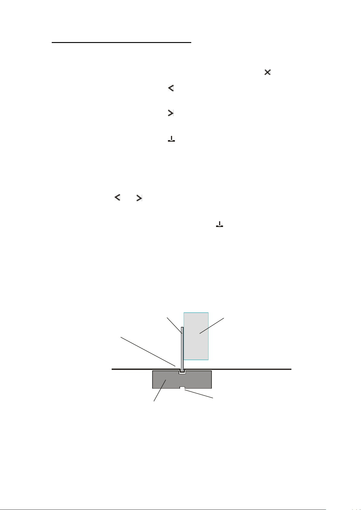
Creasing Knife Holder
In ‘run’ mode the feed motor and/or crease motor may be stopped at any time by
pressing any of the four keys. To restart the feed motor, press the key.
If the feed motor is stopped and the key is pressed, the sheet counter is reset to
zero.
If the feed motor is stopped and the key is pressed, the machine will go back to
‘setup’ mode.
If the feed motor is stopped and the key is pressed, the feed motor will run. The
machine has entered ‘edit’ mode. This is indicated by the presence of a decimal point
in the second position of the screen. This allows small changes to be made to the
existing program. Creases may not be added or deleted in this mode.
• Feed a sheet into the creaser, it will be fed to the first crease position and then the
feed motor will stop.
• By pressing the and keys the crease position may be adjusted. The position
of the potential crease is displayed in millimetres from the leading edge or last
crease.
• When the crease position is reached, press the key and the crease head will
operate. The feed motor will then feed the sheet to the next crease position (if
there is one) or eject the sheet.
A slide-out, reversible creasing matrix allows card up to 350gsm to be creased.
Creasing Knife
Wide tool for 200gsm
and greater
Creasing Tool
Narrow tool for
200gsm and lower
Page 5
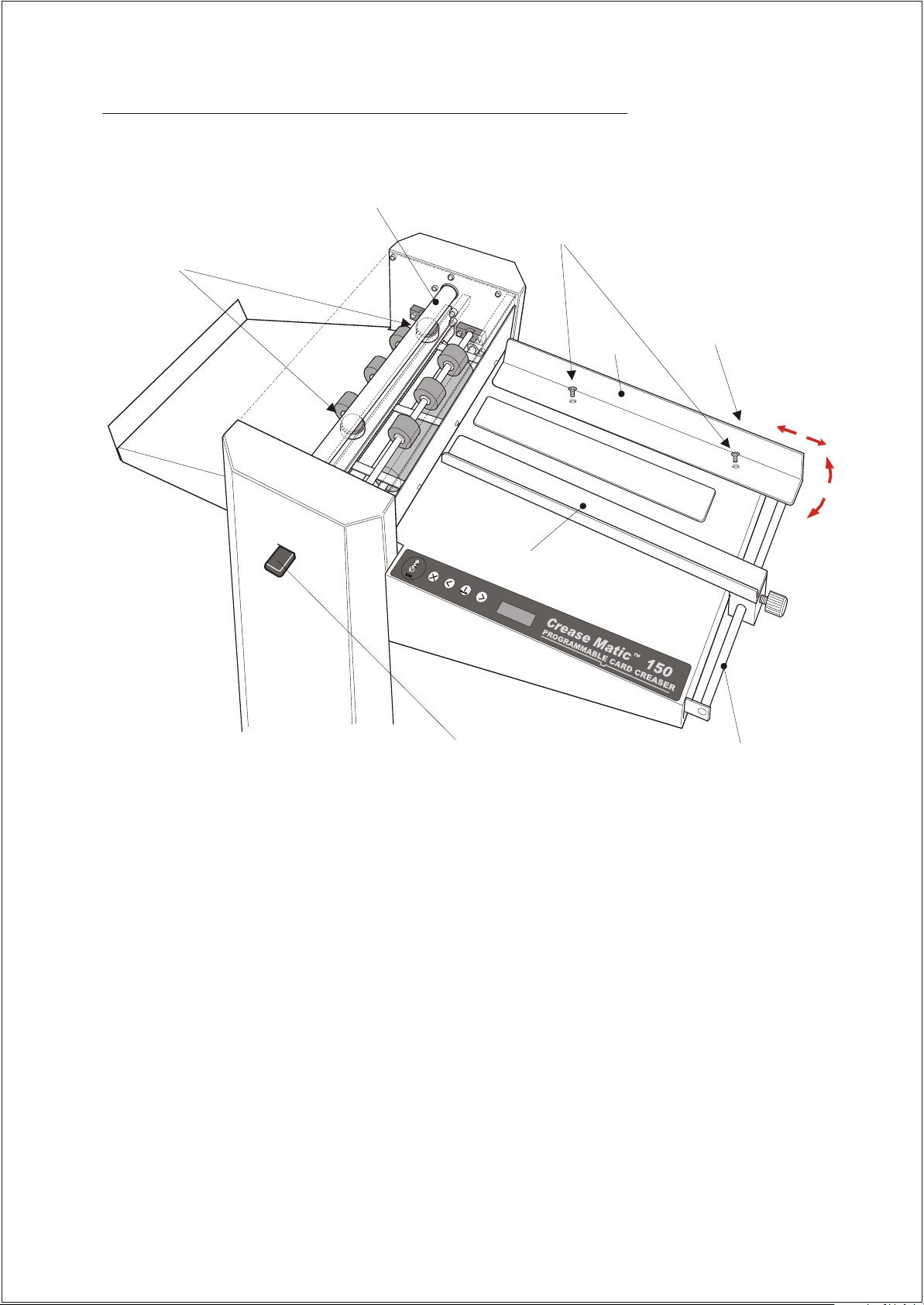
Crease Matic 150 mechanical adjustment and maintenance:
Knife Driver
2) Screws for Adjustment
1) Knife Depth
Adjustment Blocks
LHS Lay
of RHS Lay
RHS Lay
3) Bolts for Adjustment
of LHS Lay
3
2
Crease Block
Turn the Power off.
1) Knife depth adjustment: Using a 13mm spanner loosen the lock nuts on both adjusters.
With the crease block set with the narrow tool up, turn the knife driver to bottom dead centre, driving
the knife down. Set the adjustment blocks so that the creasing block has very little room to move,
i.e. It does not rattle when moved but can be slid back out of the machine. Re-tighten the two lock nuts.
Do not adjust these two blocks so that the knife driver can no longer be rotated freely. After setting,
rotate the knife driver by hand and ensure there is no ‘sticking’ point as the knife driver goes through
the bottom of its arc.
2) Right hand side lay adjustment: Using a flat head screwdriver, loosen the two countersunk screws
in the side lay. The angle of the lay to the crease knife may now be adjusted. Re-tighten the two screws.
3) Left hand side lay adjustment: Using a 10mm spanner loosen the two bolts in the vertical panel
beneath the right hand side lay. The left hand side lay support bar may now be move towards or away
from the feed table to adjust the angle of the left hand side lay to the knife. Re-tighten the two bolts.
4) Periodically check to ensure that the two areas of the knife driver that contact with the knife
adjustment blocks are lubricated.
5) Periodically clean the feed rolls to ensure an accurate crease position. A dry cloth should only be used.
LHS Lay Support Bar
Page 6

New Job Setup:
1. Ensure Crease Matic is in ‘setup’ mode. Decimal
point in last position of screen and LED off. Select
job number to program, then press ‘crease’.
3. Press the ‘left’ key until distance from edge
is reached (99.00mm). Press creaser button
2. Push card gently to infeed wheels. The Crease
Matic will feed the card to the creasing blade.
4. Press forward again until distance from
1st crease is reached (198.00mm).
Press creaser button
5. Press forward again until sheet is out onto the
collection tray, the next sheet will now go in and the
same creases will be repeated,
6. Press forward again until sheet is out onto
the collection tray, the next sheet will now go in and the
same creases will be repeated,
Page 7

CROSS
Power on Reset memory
Sensor to crease = 16
Setup mode
Last D.P. on screen
Setup
Last D.P. on screen
Run mode
Green LED
Exit to run Index job Setup job Display job
Exit to run Forward Crease and save setting Back (slow)
Start
Stop (if motor running)
LEFT
Edit sensor to crease
Reset counter
Stop (if motor running)
CREASE
distance setting
Edit job
Stop (if motor running)
RIGHT
If ‘9999’ displayed at
start up. Press to reset
knife
Exit to setup
Stop (if motor running)
Edit
Second D.P. on screen
D.P. = Decimal point Distances in millimetres
Exit to run Forward (dead slow) Crease Back (dead slow)
Page 8

CROSS
Po wer on If ‘9999’ displayed at
Setup mode
Last D.P. on screen
Setup
Last D.P. on screen
Run mode
Green LED
Exit to run Index job Setup job Display job
Exit to run Forward Crease and save setting Back (slow)
Start
Stop (if motor running)
LEFT
Reset counter
Stop (if motor running)
CREASE
Edit job
Stop (if motor running)
RIGHT
start up. Press to reset
knife
Exit to setup
Stop (if motor running)
Edit
Second D.P. on screen
D.P. = Decimal point Distances in millimetres
Exit to run Forward (dead slow) Crease Back (dead slow)
Page 9

Top perforating wheel
is pushed against spring
as perforator is closed
Upper
perforator
wheel
Do not adjust
this screw
Upper shaft
Control wheel
1/8”(3.17mm)
Position of Perforating wheels when in open position
1/4” (6.35mm)
Control wheel
Lower shaft
Lower
perforating
wheel
Position of perforating wheels when in closed position
Perforator Set-up
Page 10
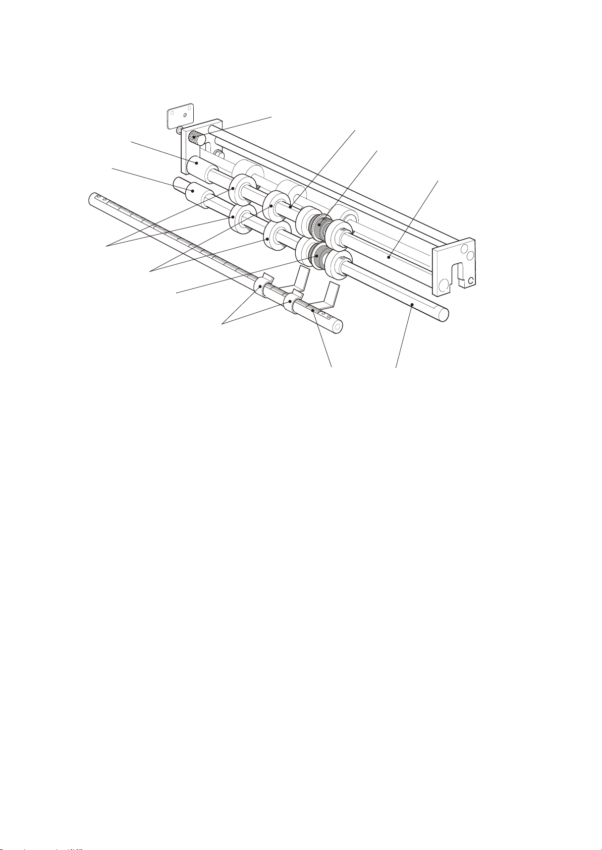
Telescopic
end piece
Collar
Control
wheels
Control wheels
Lower perforating
wheel
Spring loaded pin
Shaft flat
Upper perforating
wheel
Top shaft
Smoother
guides
Rule
Perforator unit
Bottom shaft
 Loading...