

Gazer CKR4400, CKR4400-xxx, CKR4413-xxx User Manual
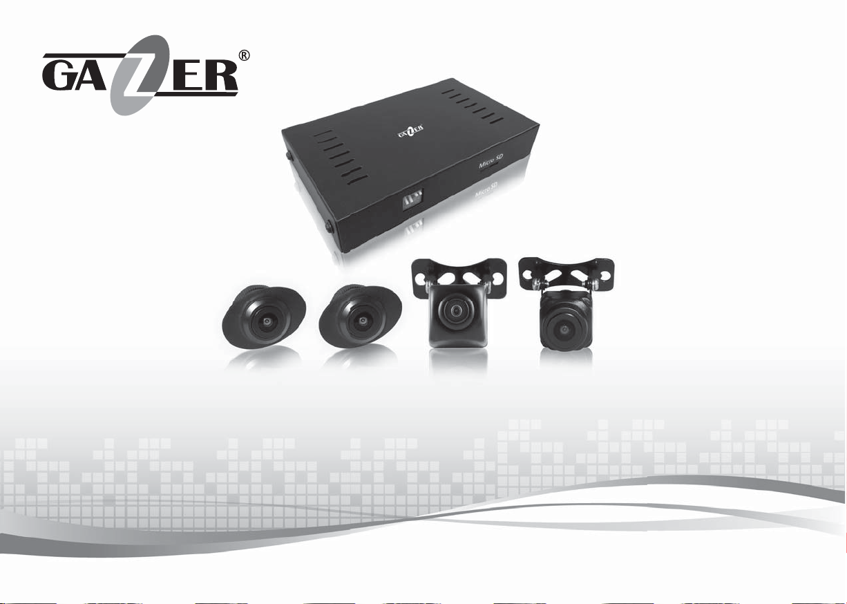
SURROUND VIEW CAMERA SYSTEM
Gazer CKR4400/4400-ххх/4413-ххх
USER MANUAL

ENG
User manual
_______________________________________________________________________________________________
4-21
Руководство пользователя
RU
Посібник користувача
UA
_________________________________________________________________________________
_____________________________________________________________________________________
22-39
40-57

Contents
Warning ............................................................................................................................................................................................... 5
ENG
Important information ........................................................................................................................................................................... 6
Package contents .................................................................................................................................................................................. 7
Controls ................................................................................................................................................................................................ 9
Installation ......................................................................................................................................................................................... 11
Setting up procedures.......................................................................................................................................................................... 13
Usage ................................................................................................................................................................................................. 17
Specifi cations ...................................................................................................................................................................................... 21
4

Warning
Congratulations on your purchase of Gazer surround view camera system.
Please, read this manual carefully before using the device.
Precautions:
• Avoid hitting, dropping and damaging the cameras and the central control unit mechanically.
• Do not attempt to repair the device yourself. In case of malfunctions, contact the vendor or the service center.
• Do not use switching units and wiring from other devices when installing the system. Failure to observe this precaution may result in
system malfunction.
• To install and connect the system without voiding your vehicle warranty, please contact an authorized service station.
• Neither the manufacturer nor the vendor shall be responsible for any damages or lost profi t due to the use or loss of information obtained
with this device.
• The manufacturer reserves the right to change product specifi cations and/or confi guration without prior notice.
ENG
5
ENG
6
T
v
Important information
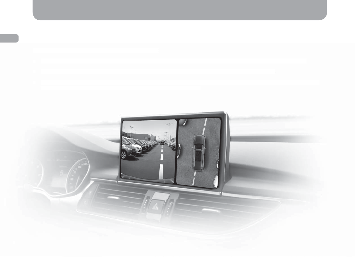
Gazer surround view DVR system consists of 4 video cameras and a special video processing unit that merges the video feed from all
cameras into a single panoramic image. You can see everything that happens around the car on the monitor in real time and in “plan view”
without any blind spots. The DVR function allows recording video from each camera separately storing it on a micro SD card or a USB drive.
he model range of Gazer surround view systems comprises:
The model range of Gazer surround view systems comprises:
• Gazer CKR4400 universal surround view system designed for installation in any car model, includes the universal video cameras;
• Gazer CKR4400 universal surround view system designed for installation in any car model, includes the universal video cameras;
• Gazer CKR4400-ххх* surround view systems with stock video cameras designed for standard installation in a car;
• Gazer CKR4400-ххх* surround view systems with stock video cameras designed for standard installation in a car;
• Gazer CKR4413-ххх* surround view systems designed for standard installation in a car, includes the stock video cameras and a special
• Gazer CKR4413-ххх* surround view systems designed for standard installation in a car, includes the stock video cameras and a special
video interface for direct Plug&Play connection to the car’s original head unit.
ideo interface for direct Plug&Play connection to the car’s original head unit.
*“ххх” in the name of the device indicates its compatibility with a speci c car model.
6
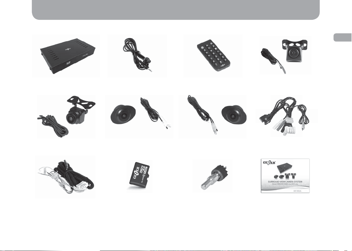
Package contents
Gazer CKR4400 surround view camera system package contents
ENG
Control unit Rear view camera
Front view camera
(black jack)
Additional connection cable
Remote IR receiver
Right side view camera
(white jack)
Remote control
Left side view camera
(yellow jack)
CutterGazer micro SDHC memory card
for the control unit
(red jack)
Сonnection cable
User manual
7
ENG
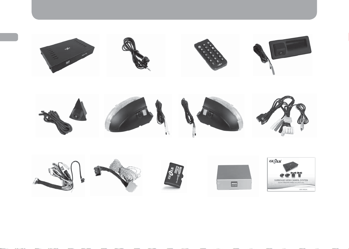
Package contents
Gazer CKR4400-ххх/4413-ххх surround view camera system package contents*
Control unit Rear view camera
Front view camera
(black jack)
Сonnection cable
for the video interface
(for Gazer CKR4413-ххх)
*Depending on the model appearance and the number of assembly components may vary.
8
Additional connection
cable (for Gazer
Remote IR receiver
Right side view camera
(white jack)
CKR4413-xxx)
Left side view camera
Gazer micro SDHC
memory card
Remote control
(yellow jack)
Video interface for
connecting to the original
head unit (for Gazer
CKR4413-xxx)
(red jack)
Сonnection cable
for the control unit
User manual

The central unit controls
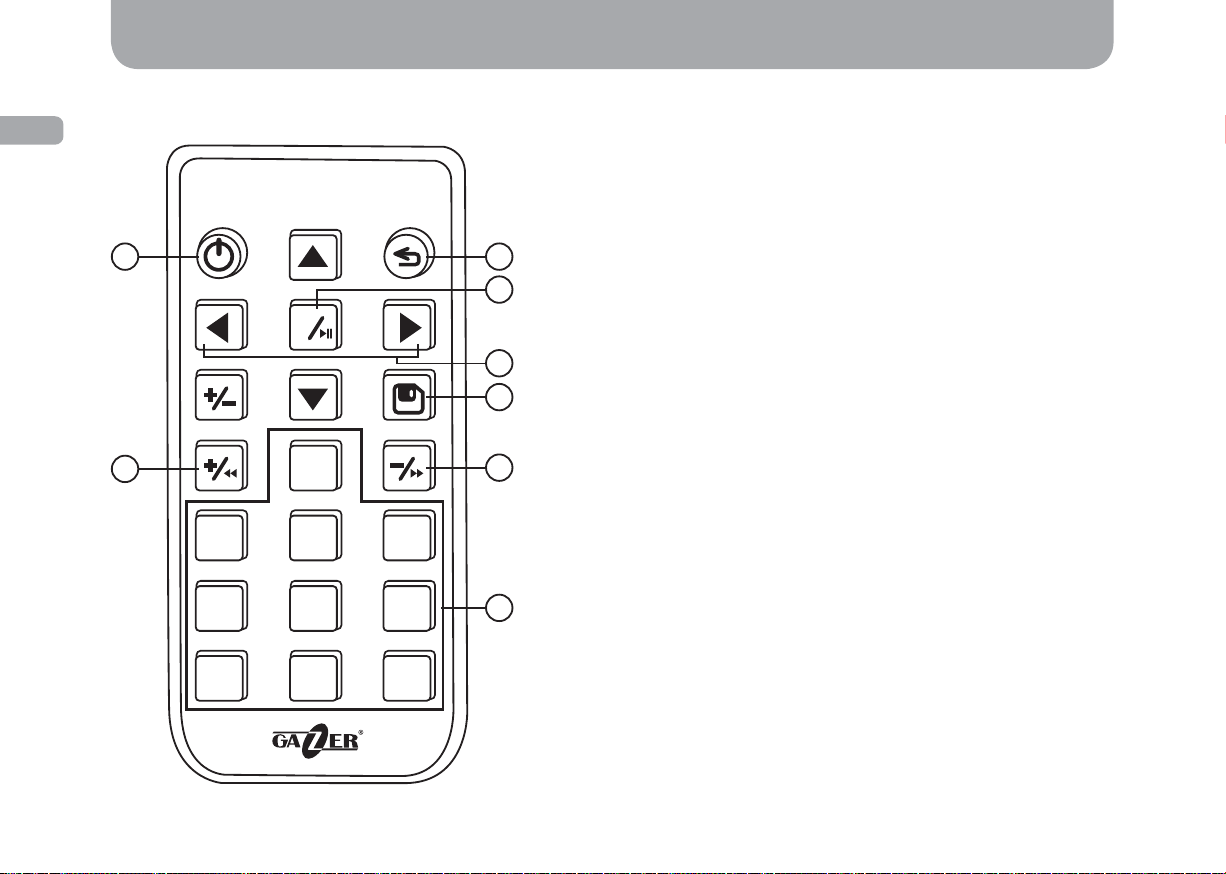
Controls
1-2. LED indicator:
blinking light – system power on;
constant light – system is operating.
3.
Socket connection.
4. Switch panel.
5. Micro SD card slot.
ENG
9
ENG
Description the remote control
1 2
ОК
Controls
1. Turn the system on/off.
2. Return to the previous menu.
3. Enter the menu;
confi rm selection
start/pause playback – in viewing mode.
4. Navigate through the menu;
3
4
5
select a camera for viewing.
5. Save settings.
6. Select parameter
skip forward – in viewing mode.
7. Entering data.
8. Select parameter
skip back – in viewing mode.
– in menu mode;
– in menu mode;
– in menu mode;
10
8
0
6
123
456
7
789
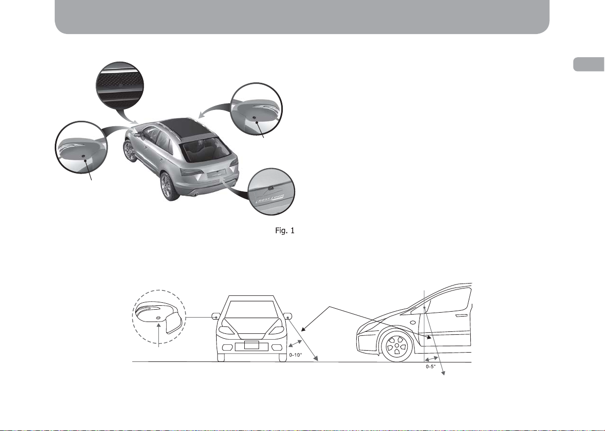
Installation
Camera mounting
Rear view camera: The rear view camera is to be mounted at least
40 cm above the ground. Depending on the model of the system,
Front view
camera
Right side
view camera
Left side view
camera
Rear view
camera
To mount universal side view cameras, one needs to make 2 symmetrical holes in the left and right wing mirrors. Once the cameras are
mounted, adjust the viewing angle as shown in the diagram below:
camera can be mounted: in a standard location (for Gazer CKR4400ххх and Gazer CKR4413-xxx models) instead of the license plate
light housing (with the light function preserved) or instead of the
trunk handle (with the button function preserved); using a universal
“butterfl y” mount (for Gazer CKR4400 model).
Front view camera: The front view camera is to be mounted
at least 40 cm above the ground. Depending on the model of the
system, the camera can be mounted: in a standard location (for Gazer
CKR4400-ххх and Gazer CKR4413-xxx models) instead of the front
car emblem or in a stock mounting seat; using a universal “butterfl y”
mount (for Gazer CKR4400 model).
Side view cameras: Side view cameras are to be mounted at least
40 cm above the ground. Depending on the model of the system,
cameras can be mounted: in a standard location (for Gazer CKR4400ххх and Gazer CKR4413-xxx models) instead of the lower parts of
wing mirrors; inside wing mirrors (for Gazer CKR4400 model).
Camera tilt
ENG
Camera
placement
Fig. 2
11
ENG
Installation
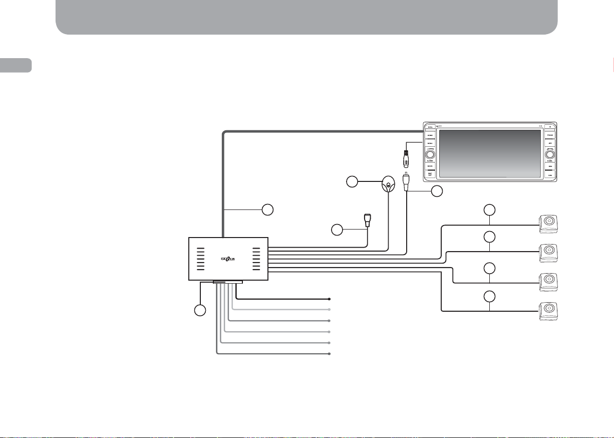
Central control unit mounting
Once the cameras are mounted, connect them to the central control unit observing the color of connection wires (Fig. 3).
Mount the central control unit in the front of the vehicle (under the steering column or under the driver’s seat). For correct operation of the
G-sensor function, fi x the central control unit tightly on the car body or any other stationary part of the car interior. Make sure you put the
USB cable in an easy-to-reach place. This way you will not have any trouble connecting a USB drive and copying video fi les.
1. Blue cable for monitor
control: switch-over to view a
surrоund video review (+12V).
2. USB port: USB drive
connection for copying video
fi les and updating fi rmware.
3. Black 3.5 mm jack: remote
control receiver connection.
4. Yellow AV jack: monitor
connection.
5. Black 4-contact jack: front
view camera connection.
6. Yellow 4-contact jack: left
side view camera connection.
7. White 4-contact jack: right
side view camera connection.
8. Red 4-contact jack: rear
view camera connection.
9. Power and control socket.
9
Blue cable for
monitor control
1
Black
Yellow
Red
Pink
Orange
Green
3
2
GND
BAT+
ACC+
Left turn signal
Right turn signal
Reverse gear signal
4
5
6
7
8
12
Fig. 3
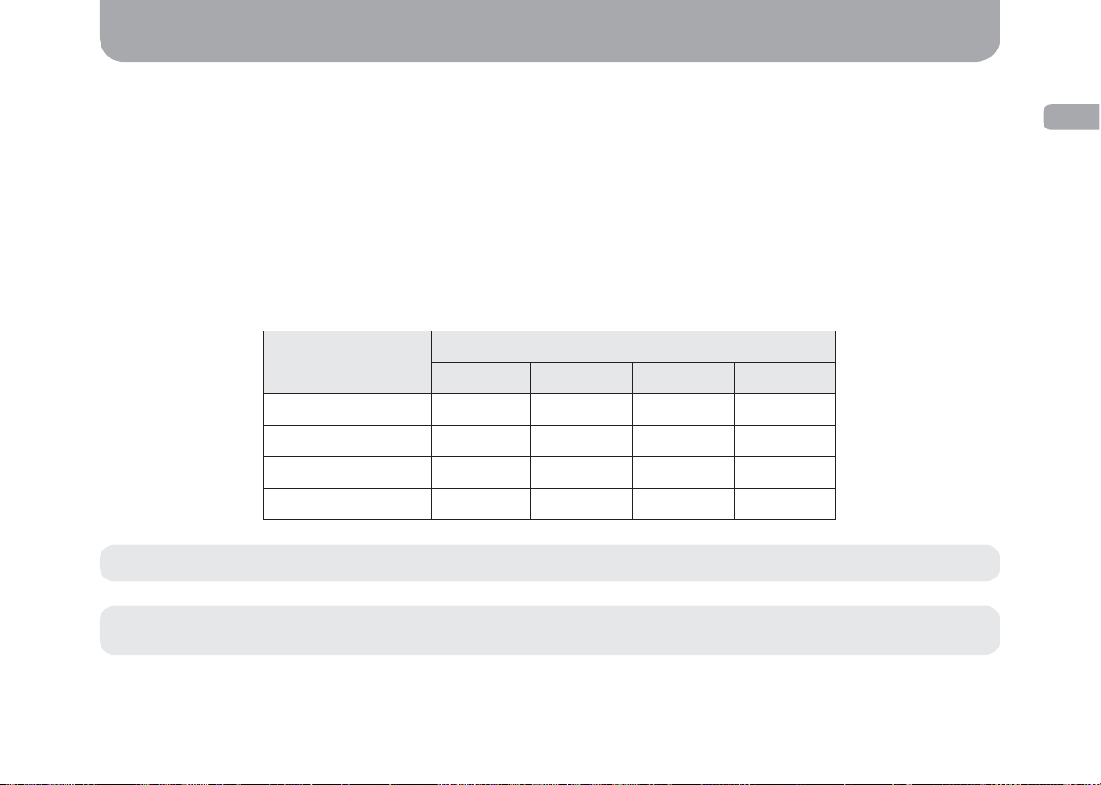
Setting up procedures
Setting up CCTV parking mode
Gazer surround view system supports CCTV function in a parked car. When this function is activated, the system stops operating after ACC
signal is off and plays back a 120 second video recording only if the shock sensor (G-sensor) is tripped. Car battery discharge control function
will prevent the car battery from a critical discharge: the system will shut down completely at 11.7 V until ACC signal is on again.
Use the switches on the device control unit to adjust the system further.
Switch No. 1 (“Up” position): force system shutdown after ACC signal is off.
Switch No. 2 (“Up” position): disable car power system voltage control (set at 11.7 V).
Switches No. 3 and No. 4: shock sensor (G-sensor) sensitivity adjustment. To adjust the shock sensor (G-sensor) sensitivity, set the
switches as shown in the diagram below:
ENG
G-sensor
Switch
№1 №2 №3 №4
Off UpUpUpUp
Level 1 Down Down Down Up
Level 2 Down Down Up Down
Level 3 Down Down Down Down
Note: To activate the CCTV parking mode, set switches No. 1 and No. 2 in “Down” position.
Attention! When installing switches No. 1 and No. 2 to the “Down” position and switches No. 3 and No. 4 to the “Up” position, a built-
in G-censor will be not active.
13
ENG
Setting up procedures
System calibration
To ensure that information from each camera is displayed correctly and the feed from all cameras is merged into a single “plan view”, one
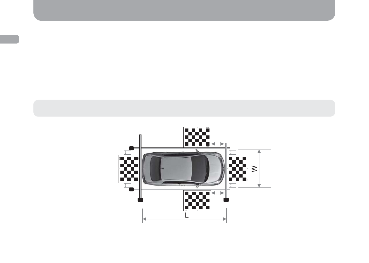
needs to calibrate the device before use. This requires: tape measure - 5 m (2 pcs) and 7.5 m (2 pcs); 1.6 m x 1.2 m calibration sheet (4 pcs).
To calibrate the system, follow the steps below:
1. Place calibration sheets in front of each camera as shown in the diagram below (Fig. 4). Red marks on the front and rear calibration
sheets must be aligned with the car’s central axis. Red marks on side calibration sheets must be aligned with the car’s wing mirrors
(mounting seats inside the mirrors).
2. Measure distances L, W, P1,and P2 (Fig. 4)
Caution! The distance from the front sheet to side sheets (P1, P2) as well as distances S1 and S2, O1, and O2 must be the same
(P1=P2; S1=S2; O1=O2).
P1
S1=S2
O1
S1
14
O1=O2
O2
P1=P2
S2
P2
Fig. 4
Setting up procedures
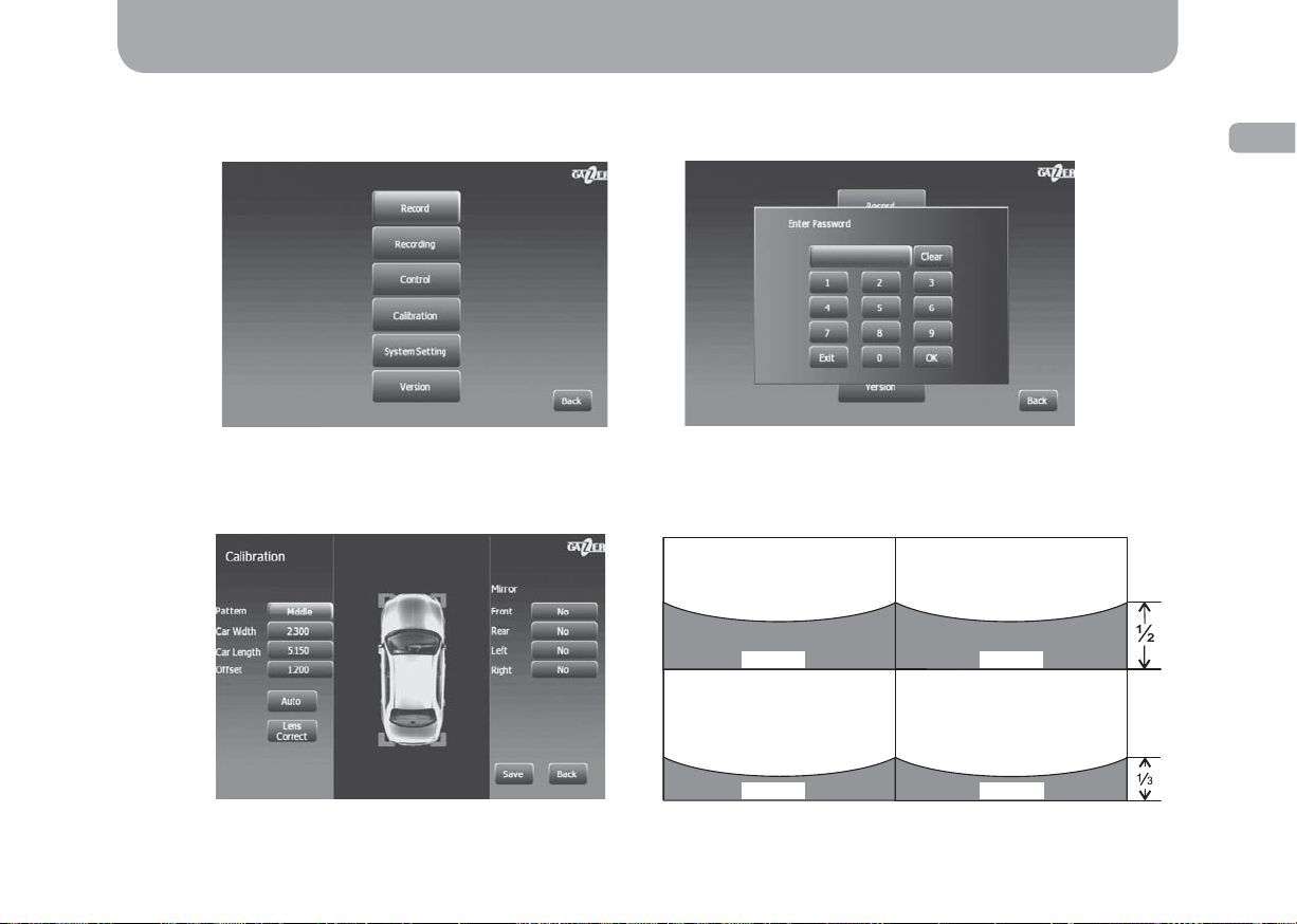
3. Use the remote control to turn on the system, then go to the settings menu, select “Calibration” (Fig. 5) and enter password: 301530
(Fig. 6).
ENG
Fig. 5
Fig. 6
4. Go to “Calibr.” (Fig. 7) and view video feed from each camera consecutively using navigation buttons on the remote control. Make sure
that the image produced by the cameras matches the one on the diagram below (Fig. 8).
Left side view camera Right side view camera
Car body Car body
Front view camera Rear view camera
Car body Car body
Fig. 7 Fig. 8
15
ENG
Setting up procedures
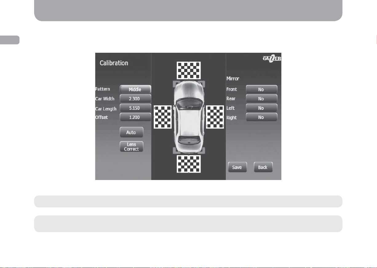
5. After adjusting the camera view, go back to the previous menu using the “Back” button on the remote control. Enter L (Length), W
(Width), P (Pan) values in the corresponding fi elds in accordance with your data and then select “Аuto” (Fig. 9) in the menu. In case
calibration was successful, you will see a panoramic “plan” view of your car without any blind spots (Fig. 9).
Fig. 9
16
Note: In case of incorrect calibration, repeat the procedure.
Recommendation: Cameras must be mounted at least 40 cm above the ground. Follow this recommendation at all times to avoid
system malfunction.
Usage
DVR function
Gazer surround view system has a 4-channel DVR function that enables it to record 704х576 videos at 30 fps. Video is recorded continuously
thanks to the loop recording function. The system switches to the recoding mode automatically when ACC signal is on or when the shock
sensor is tripped in the parking mode.
Note: Current consumption is less than 12 mA in the parking mode when the device is in the standby mode.
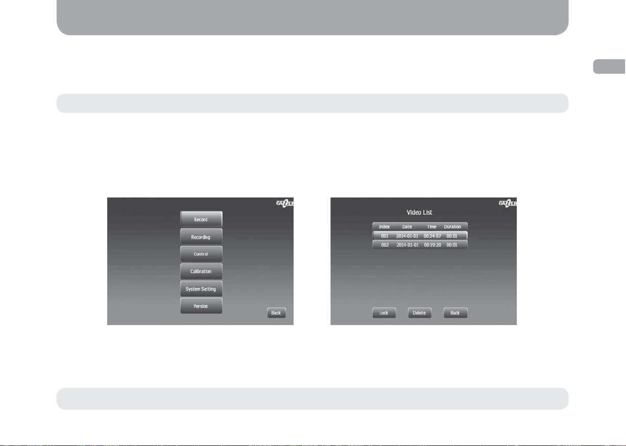
Video clips are stored on a micro SD memory card or a USB drive. To view and manage recorded video fi les, go to “Record” in the menu and
select the required fi le from the list. To select or change the storage location of your video fi les, go to “Recording”/“Storage Location” and
then select the appropriate value.
Settings menu
“Record”: recorded fi les list. When selecting the required video fi le from the list, you can block it from loop overwriting. To do this, press the
“Left” button on the remote control and then select “Lock” in the settings menu.
ENG
Fig. 10 Fig. 11
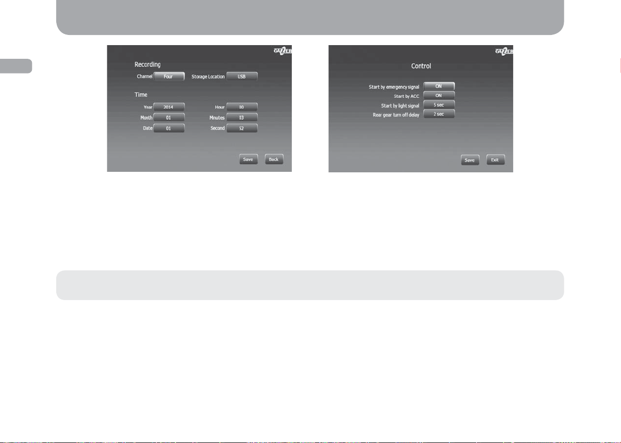
“Recording”: recording, date and time settings.
“Channel”: select the source of recording. One can select a signle camera or four cameras simultaneously.
“Storage Location”: select a storage device for saving recorded video clips (SD memory card or USB drive).
Note: Do not eject the SD memory card or USB drive when the device is on. This may cause it to malfunction.
17
ENG
Usage
18
Fig. 12
“Control”: system startup settings.
“Start by emergency signal”: 3 seconds after the car’s hazard warning button is pressed the system will turn on and display the image on
the monitor.
“Start by ACC”: the system will turn on and display the image on the monitor when the ignition key is turned (АСС “Accessories” signal is
on). The system will shut down only after ACC signal is off.
“Start by light signal”: the system will power on and display the image on the monitor when the car’s turn light is on.
Note: It is possible to adjust the automatic screen timeout in “Start by emergency signal”, “Start by ACC”, “Start by light signal” menu
items.
“Rear gear turn off delay”: adjust the screen timeout after the reverse gear is off.
Fig. 13
Usage
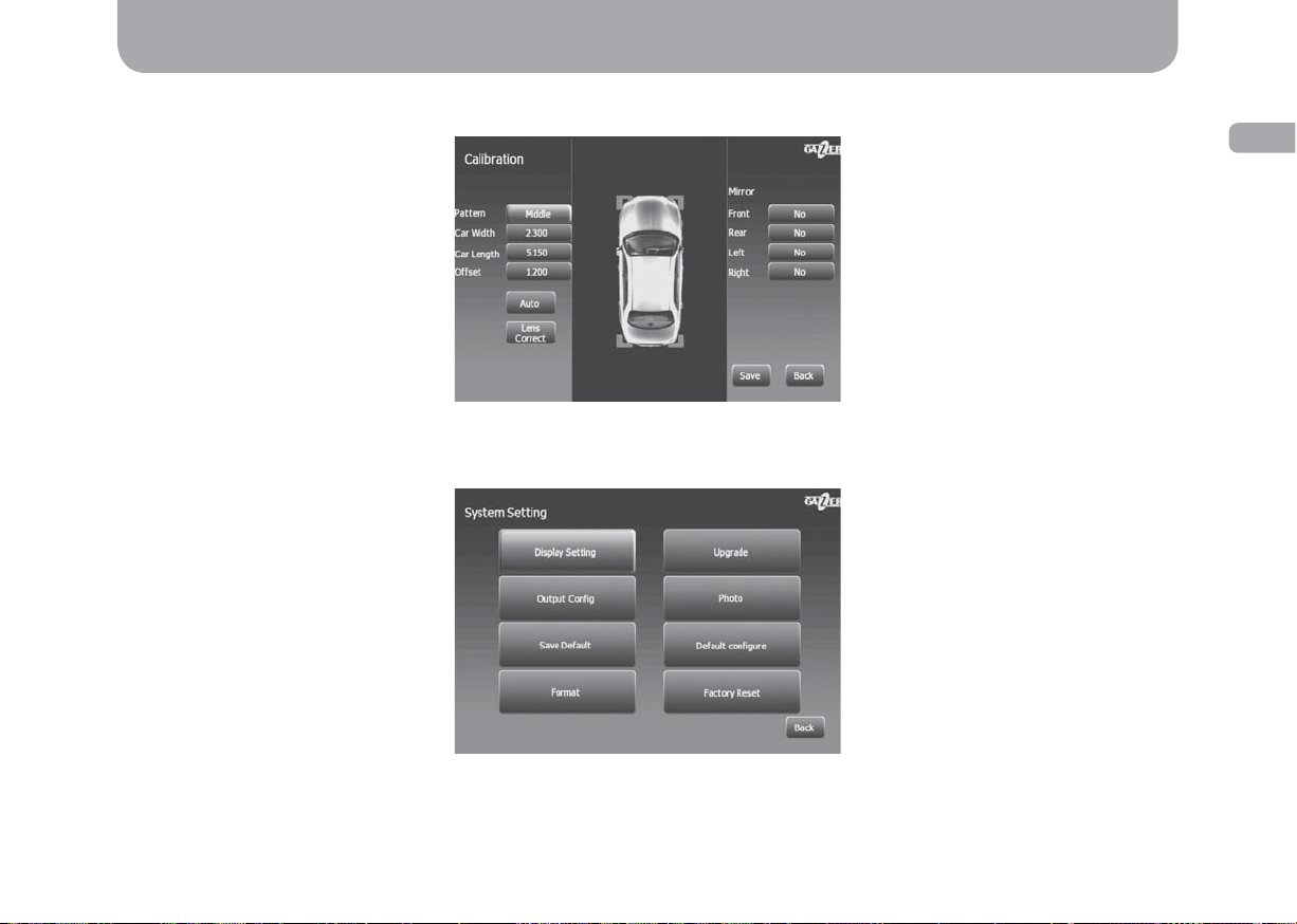
“Calibration”: camera calibration settings (see “Calibration”, p. 14-16).
“System Setting”: screen setup and save settings menu.
ENG
Fig. 14
Fig. 15
19
 Loading...