

Gazer CC100, CC100-XXX, CC100-XXX-L User Manual


User manual 4-12
ENG
Руководство пользователя 13-21
RU
Посібник користувача 22-30
UA
3

Congratulations on your purchase of Gazer car camera.
Please read this manual carefully before using the product.
Avoid impacts, falls and mechanical damage of the camera.
Do not attempt to repair the camera yourself, for it may lead
to a loss of integrity.
In case of a fault, contact your dealer or service centre.
Do not use switching blocks and wiring of other devices during
installation. Such a connection may result in camera
malfunction.
To install and connect the camera without voiding your car’s
warrant, please consult with the personnel of service
stations where your car is serviced.
Warnings
Gazer CC100/CC100-XXX/CC100-XXX-L
1. Warnings 5
EN
G
2. Package contents 6
3. Important information 7
4. Connection scheme 9
5. Camera installation 11
6. Specifications 12
Contents
4

Gazer CC100/CC100-XXX/CC100-XXX-L
Congratulations on your purchase of Gazer car camera.
Please read this manual carefully before using the product.
Warnings
Avoid impacts, falls and mechanical damage of the camera.
Do not attempt to repair the camera yourself, for it may lead
to a loss of integrity.
In case of a fault, contact your dealer or service centre.
Do not use switching blocks and wiring of other devices during
installation. Such a connection may result in camera
malfunction.
To install and connect the camera without voiding your car’s
warrant, please consult with the personnel of service
stations where your car is serviced.
EN
G
5
Important information
Backup camera Gazer CC100 has a universal car body mount.
Gazer models CC100-XXX and CC100-XXX-L are based on
Gazer CC100 cameras and designed for installation in the
license plate light housing (video camera is integrated into the
lamp body). Model CC100-XXX uses the original number plate
light (the lamp mounting and socket connection are identical to
the original car lamp). Model CC100-XXX-L uses LED license
plate light (color temperature 2700K). «XXX» code in the
camera name indicates compatibility with the factory code of
the original license plate light lamp.
Gazer CC100 camera transmits mirror-like video signal, so that
driver could rely on the video feed from the camera as he/she
would do when looking in the rear view mirror.
The image displayed by the camera has a parking assist
overlay (red, yellow and green lines). These lines have
curvature (repeating the curvature of objects in a wide-angle
lens camera) and indicate the same distance to the obstacles
across the full width of the visible image. Distance from car to
each guidance line depends on the car model (mounting height
and camera tilt). The driver must estimate (or measure) the
actual distance to each of the guidance lines on his/her car.
Attention!
Objects behind the vehicle are closer than they
appear in the camera-produced image. To avoid accidents and
injuries while driving in reverse, do not rely only on the rear
view camera. Be sure to always check the situation around the
car and monitor the situation in the rear-view mirror.
EN
G
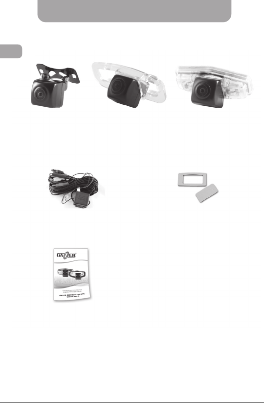
Gazer CC100 Gazer CC100-XXX-LGazer CC100-XXX
АС100 switching and
control unit
Package
Sealing gasket
(optional)
6
User manual

Important information
Backup camera Gazer CC100 has a universal car body mount.
Gazer models CC100-XXX and CC100-XXX-L are based on
Gazer CC100 cameras and designed for installation in the
license plate light housing (video camera is integrated into the
lamp body). Model CC100-XXX uses the original number plate
light (the lamp mounting and socket connection are identical to
the original car lamp). Model CC100-XXX-L uses LED license
plate light (color temperature 2700K). «XXX» code in the
camera name indicates compatibility with the factory code of
the original license plate light lamp.
Gazer CC100 camera transmits mirror-like video signal, so that
driver could rely on the video feed from the camera as he/she
would do when looking in the rear view mirror.
The image displayed by the camera has a parking assist
overlay (red, yellow and green lines). These lines have
curvature (repeating the curvature of objects in a wide-angle
lens camera) and indicate the same distance to the obstacles
across the full width of the visible image. Distance from car to
each guidance line depends on the car model (mounting height
and camera tilt). The driver must estimate (or measure) the
actual distance to each of the guidance lines on his/her car.
Attention!
appear in the camera-produced image. To avoid accidents and
injuries while driving in reverse, do not rely only on the rear
view camera. Be sure to always check the situation around the
car and monitor the situation in the rear-view mirror.
Objects behind the vehicle are closer than they
EN
G
7
Important information
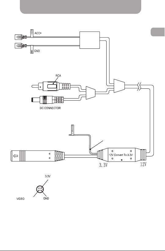
Connection scheme
Scheme of switching and control block Gazer AC100
(red)
(red)
(red)
(purple)
CONTROL WIRE
(white)
(black)
(black)
Сamera сonnector
CONTROL
UNIT
(yellow)
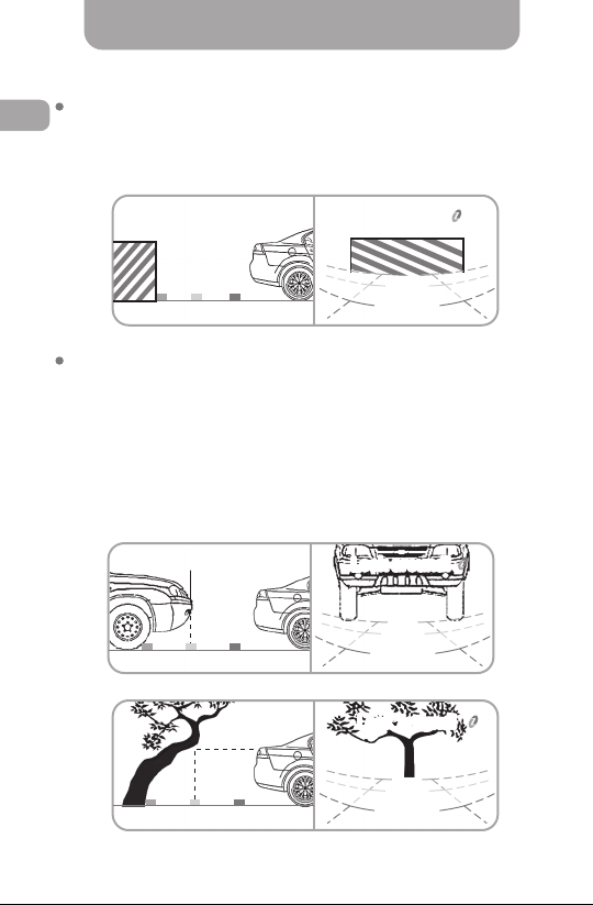
When approaching vertically positioned (perpendicular to the
EN
G
roadway) objects and objects or obstacles placed directly on the
roadway (wall, pillar) the actual distance to such obstacles
corresponds to distance calculated by the parking guidance
system.
Look around!
When approaching objects or obstacles positioned at an angle in
relation to the roadway (a tilted tree) or placed above the
roadway (the bumper of another car), the actual distance to the
obstacle does not correspond to the distance of the assist
guidance lines. It should be noted that the auxiliary guidance
lines are projected on the part of obstacle located at the
roadway level. If the obstacle is tilted in relation to the vehicle
or located above the roadway level, it is closer to the car than
the assist guidance lines suggest.
real obstacle
visible obstacle
real obstacle
Look around!Look around!
Look around!
Look around!
visible obstacle
8
(red)
(black)
Сamera сonnector
Connection scheme
CONTROL
UNIT
(yellow)
(red)
CONTROL WIRE
(purple)
(red)
EN
G
(white)
(black)
Scheme of switching and control block Gazer AC100
9

Connection scheme
Camera installation
Installing Gazer СС100-XXX/СС100-XXX-L camera
Disconnect the AC power light plate and remove the lamp lighting.
If necessary, relocate the lamp socket and light plug connector
from the original housing to Gazer CC100-XXX camera housing.
Install the license plate light lamp into the camera housing.
Connect the license plate light power connector.
If you use Gazer CC100-XXX-L camera (with LED-based backlight),
connect the power wires of the camera lights to the power wires of
car license plate light (red wire +12V, black wire – vehicle earth).
Connect the camera to the switching and control block, as shown
on p. 9-10. Install Gazer camera instead of the license plate light
lamp.
To connect a Gazer car camera or install a video parking system
EN
G
with Gazer car monitor or Gazer rear-view mirror with a built-in
monitor, use Gazer AC100 switching and control unit supplied
with the Gazer car camera.
Connect the black wire (GND) to the car ground line and the red
wire (ACC +) to the car’s ACC supply line (ACC power goes ON
and OFF automatically when the car engine is ON or OFF).
Connect the camera’s RCA video output to the monitor’s RCA
video input, and the switching unit power connector (DC
CONNECTOR) to the monitor’s power connector.
Connect the purple wire (REVERSE) to the reverse lights power
wire +12V. Connect the camera connector to the corresponding
switching unit connector.
Once connected this way, the switching and control unit will
simultaneously supply power to the camera and the monitor
whenever the car is put in the reverse gear (backup lamps light
up). In this case, this image from the rear view camera is
displayed on the monitor screen automatically.
Note. For correct Gazer video parking system
installation, please contact your dealer or service station.
To avoid warranty loss, if your car is still under warranty,
please contact the warranty service station.
10
 Loading...