

Gazelle GZ1700, GZ1700C, GZ1720E, GZ2000C, GZ2000 Operator's Manual
...
Operator’s Manual
Electric In-Line Burnisher
Failure to read and understand this manual
before operating this machine or performing service on
this machine may result in injury to the operator or
nearby personnel or result in damage to the machine
or nearby property. Each operator must be trained in
the operation of this machine before being allowed to
use it. Contact Amano Pioneer Eclipse Customer
Service at 1-800-367-3550 or 1-336-372-8080 or an
authorized Amano Pioneer Eclipse Distributor to
inquire about training or to request a replacement
manual.
La falta de leer y de entender este manual antes de
usar esta máquina o de realizar servicio en esta
máquina puede dar lugar a lesión al operador o al
personal próximo o a resultado en daño a la máquina
o propiedad próxima. Cada operador debe ser
entrenado en la operación de esta máquina antes de
ser permitido utilizarla. Ponerse en contacto con el
servicio de Amano Pioneer Eclipse 1-800-367-3550 o
1-336-372-8080 o un distribuidor autorizado por
Amano Pioneer Eclipse para investigar sobre el
entrenamiento o para solicitar un manual.
Manquer de lire et de comprendre ce manuel
d'utilisation avant l'utilisation de cette machine ou
avant faire de maintenance sur la machine peut être
résulter en blessure à l'opérateur ou au personnel
proche ou peut endommagé la machine ou la propriété
proche. Chaque utilisateur doit être entraîné dans
l'opération de cette polisseuse avant l'utilisation.
Veuillez contacter le service àpres-vente de Amano
Pioneer Eclipse à 1-800-367-3550 ou 1-336-372-8080
et/ou un distributeur de Amano Pioneer Eclipse pour
vous renseigner concernant l'entraînement ou pour
obtenir un autre manuel d'utilisation.
For Models:
GZ1700 GZ2000C
GZ1700C GZ2020E
GZ1720E GZ2020K
GZ2000

Record This Important Information
Date of Purchase
Purchased From
Address
City State Zip
Phone Contact
Machine Model
Machine Serial Number
Important Phone Numbers
Medical Emergency
Police
Fire Department

Performance:
GZ1700, GZ1700C, GZ1720E: 12,750 sq ft/hr
(1,170 m
2
)
GZ2000, GZ2000C, GZ2020E, GZ2020K:
15,000 sq ft/hr (1,380 m2)
Motor:
2,156 Watt
Filter:
Cloth filter, 210 sq in (1,355 cm2) surface area
Power:
GZ1700, GZ1700C, GZ2000, GZ2000C:
AC110V, 60HZ, 15A
GZ1720E, GZ2020E, GZ2020K:
AC230V, 50HZ, 9A
Electrical Consumption:
1,725 Watt
Electrical Cord Length:
GZ1700, GZ1700C, GZ2000, GZ2000C:
49.2 ft (15 m)
GZ1720E, GZ2020E, GZ2020K: 75 ft (22,9 m)
Pad Size/Buffing Width:
GZ1700, GZ1700C, GZ1720E: 17 in (43,2 cm)
GZ2000, GZ2000C, GZ2020E, GZ2020K:
20 in (50,8 cm)
Pad Speed:
GZ1700, GZ2000, GZ2020K: 2000 rpm
GZ1700C, GZ2000C: 1750 rpm
GZ1720E, GZ2020E: 1667 rpm
Width:
GZ1700, GZ1700C, GZ1720E: 19.5 in (49,5 cm)
GZ2000, GZ2000C, GZ2020E, GZ2020K:
22.3 in (56,6 cm)
Length:
GZ1700, GZ1700C, GZ1720E: 29.0 in (73,7 cm)
GZ2000, GZ2000C, GZ2020E, GZ2020K:
33.5 in (85,0 cm)
Height:
46 in (116,8 cm)
Weight (Mass):
GZ1700, GZ1700C, GZ1720E: 110 lb (49,9 kg)
GZ2000, GZ2000C: 131 lb (59,4 kg)
GZ2020E, GZ2020K: 124.8 lb (56,6 kg)
Sound Level:
less than 76 dB(A)
Vibration at Handle:
Does not exceed .5 m/s
2
Specifications

Preparing and Operating the Gazelle
Uncrating . . . . . . . . . . . . . . . . . . . . . . . . . . . . . . . . . . . . . . . . . . . . . . . . . . . . . . . . . . . . . .1
Moving the Unit . . . . . . . . . . . . . . . . . . . . . . . . . . . . . . . . . . . . . . . . . . . . . . . . . . . . . . . . .1
Installing the Pad . . . . . . . . . . . . . . . . . . . . . . . . . . . . . . . . . . . . . . . . . . . . . . . . . . . . . . .1
Removing the Pad . . . . . . . . . . . . . . . . . . . . . . . . . . . . . . . . . . . . . . . . . . . . . . . . . . . . . . .2
Machine Operation . . . . . . . . . . . . . . . . . . . . . . . . . . . . . . . . . . . . . . . . . . . . . . . . . . . . . . 2
Adjusting the Pad Pressure . . . . . . . . . . . . . . . . . . . . . . . . . . . . . . . . . . . . . . . . . . . . . . . .3
Resetting the Circuit Breaker . . . . . . . . . . . . . . . . . . . . . . . . . . . . . . . . . . . . . . . . . . . . . . 4
Dust Disposal . . . . . . . . . . . . . . . . . . . . . . . . . . . . . . . . . . . . . . . . . . . . . . . . . . . . . . . . . .4
Storage . . . . . . . . . . . . . . . . . . . . . . . . . . . . . . . . . . . . . . . . . . . . . . . . . . . . . . . . . . . . . . .4
Repacking . . . . . . . . . . . . . . . . . . . . . . . . . . . . . . . . . . . . . . . . . . . . . . . . . . . . . . . . . . . . .4
Safety Guidelines . . . . . . . . . . . . . . . . . . . . . . . . . . . . . . . . . . . . . . . . . . . . . . . . . . . . . . .5
Machine Care
Cleaning the Machine . . . . . . . . . . . . . . . . . . . . . . . . . . . . . . . . . . . . . . . . . . . . . . . . . . . . 6
Pad Care . . . . . . . . . . . . . . . . . . . . . . . . . . . . . . . . . . . . . . . . . . . . . . . . . . . . . . . . . . . . . 6
Routine Machine Inspection . . . . . . . . . . . . . . . . . . . . . . . . . . . . . . . . . . . . . . . . . . . . . . . 6
Replacing the Dust Skirt . . . . . . . . . . . . . . . . . . . . . . . . . . . . . . . . . . . . . . . . . . . . . . . . . . 6
Troubleshooting . . . . . . . . . . . . . . . . . . . . . . . . . . . . . . . . . . . . . . . . . . . . . . . . . . . . . . . . . 7
Machine Drawings and Parts Lists
Machine Diagram . . . . . . . . . . . . . . . . . . . . . . . . . . . . . . . . . . . . . . . . . . . . . . . . . . . . . . .9
Wiring Diagram: GZ1700, GZ1700C, GZ2000, GZ2000C . . . . . . . . . . . . . . . . . . . . . . . . .10
Wiring Diagram, GZ1720E, GZ2020E, GZ2020K . . . . . . . . . . . . . . . . . . . . . . . . . . . . . . .11
Belt Drive and Dust Collection . . . . . . . . . . . . . . . . . . . . . . . . . . . . . . . . . . . . . . . . . . . . .12
Handle and Motor Cover . . . . . . . . . . . . . . . . . . . . . . . . . . . . . . . . . . . . . . . . . . . . . . . . .16
Warranty
Contents

1
Uncrating
The Gazelle comes packed in a carton box designed
to protect and hold the machine in place during
shipment.
1. Inspect shipping carton for damage!
If carton has been damaged, note on shipping
bill before signing.
2. Place carton box carefully on floor, remove staples
and pull machine out of the box.
3. Check entire machine for damage.
If machine is damaged, file a claim with the
freight carrier immediately!
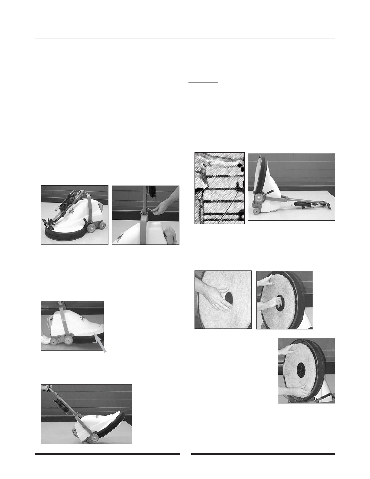
4. The Gazelle is equipped with a folding handle and
is packaged with the handle in the folded position
(Figure 1). Unfold the handle by lifting it to the
upright position and latching (Figure 2). The latch
can be adjusted for tightness.
Moving the Unit
1. Lock the handle in its upright position.
2. Holding the handle, lift the front of the pad motor
section off the floor (Figure 3).
3. Use the rear (small) wheels to move the unit
(Figure 4). When moving the machine to a higher
level floor, use the rear wheels and pull the unit
backwards instead.
Installing the pad
The Gazelle comes with a pad already installed.
Amano Pioneer Eclipse pads are recommended.
CAUTION! Never operate the machine without a
pad installed!
1. Make sure the power cord is disconnected from
the power source. DO NOT install pad when the
unit is connected to the power source.
2. Place the handle perpendicular to the floor
(Figure 5). The handle and pad motor section are
locked in place.
3. Lay the unit on the floor (Figure 6).
4. Align the center hole of the pad with the pad guide
on the pad holder (Figure 7).
5. Insert the pad retainer through the hole on the pad
and rotate clockwise two or three turns until pad is
loosely retained (Figure 8).
6. Turn the pad lightly to make
sure it rotates evenly
(Figure 9). If the pad is
uneven, its vibration will
cause damage to the
seal skirt.
7. Always adjust the pad
pressure to the lowest
position when a new pad is installed. Allow a
minimum of five minutes of burnishing time to
break in the pad before adjusting the pad pressure
to a higher setting. Failure to allow the pad time to
break in can result in tripping of the machine
and/or the site circuit breaker.
Preparing and Operating the Gazelle
Figure 1
Figure 2
Figure 3
Figure 4
Figure 5
Figure 6
Figure 7
Figure 8
Figure 9
Preparing and Operating the Gazelle
2
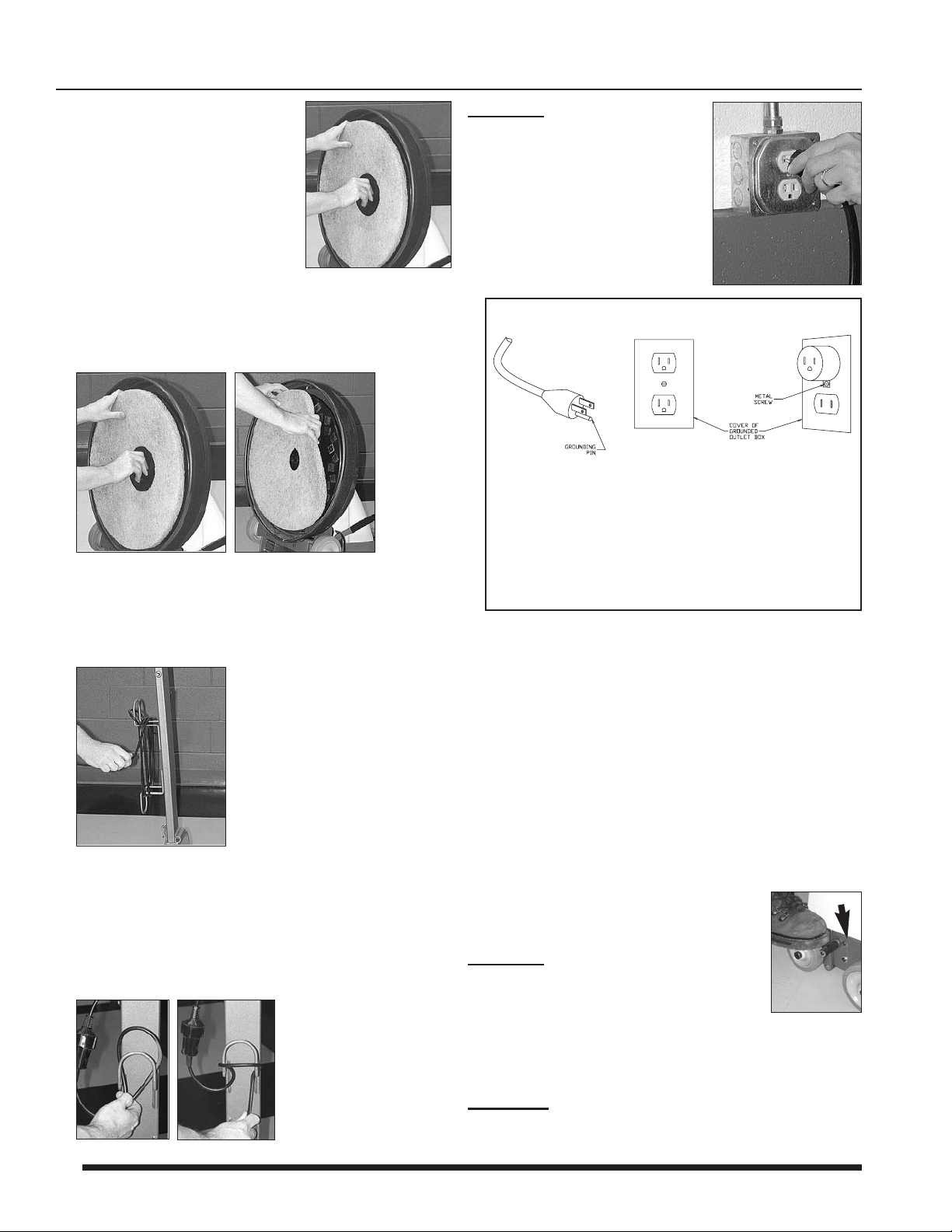
8. Holding the pad secure with
one hand, tighten the pad
retainer by turning it clockwise
(Figure 10).
9. Lift the unit to its standing
position. DO NOT allow the
machine to fall to the floor.
Removing the pad
1. Holding the pad secure with one hand, turn the pad
retainer counter-clockwise and remove (Figure 11).
2. Detach the pad from the pad holder (Figure 12).
Machine Operation
1. Unwrap the electrical cord from the cord hooks.
Check to make sure a pad is installed.
2. Secure the power cord before connecting to a
GROUNDED wall receptacle.
• Form a loop in the power cord and pass up
through the top of the cord holder (Figure 14).
• Bring the loop over the cord holder, and pull to
tighten (Figure 15).
CAUTION!
Always secure cord.
Be careful not to trip over
the electrical cord.
• Insert the plug into a
GROUNDED electrical wall
outlet or receptacle
(Figure 16).
This is a commercial electric burnisher, use only on
a dedicated circuit. Do not use on circuits with other
electrical equipment. The minimum amperage of the
site electrical breakers should be as follows:
GZ1700/GZ2000- 20A, GZ1700C/GZ2000C - 15A,
GZ1720E/GZ2020E/GZ2020K - 10A.
Use only the extension cord supplied with the
burnisher. Do not use more than one extension
cord. The total length of the extension cord should
not exceed 50 feet (GZ1700, GZ2000, GZ1700C,
GZ2000C) or 25 meters (GZ1720E, GZ2020E,
GZ1720K).
3. Holding the operating handle, step on
the handle release pedal (Figure 17).
The handle is now unlocked.
CAUTION!
Never begin operation when
the handle is locked in its upright
position.
4. Hold the handle at a comfortable height.
Hold the cord together with one grip to keep it out of
the buffing area.
W
ARNING! Do not allow the power cord to come
into contact with the rotating pad.
Figure 10
Figure 12Figure 11
Figure 13
Figure 14
Figure 15
Figure 16
Figure 17
This floor machine is provided with a grounded
plug as shown. It is intended for use on a nominal
120 volt circuit. If a properly grounded receptacle is
not available, an adapter should be installed as
shown if the outlet box that houses the receptacle
is grounded. Be sure to fasten the grounding tab
with a metal faceplate screw.
120V Machines:

3
Preparing and Operating the Gazelle
5. Push the safety button with one hand while grasping
one of the handle levers (Figure 18).
6. When the pad begins to spin release the safety
button but continue to grasp one of the handle levers
(Figure 19).
CAUTION!
This machine is for dry floor buffing only.
Do not use for scrubbing with water or cleaner.
CAUTION!
Do not leave the machine in one spot
while the pad is spinning. This may damage
the floor.
7. Begin burnishing
(Figure 20).
CAUTION!
Releasing the
grips while the pad is
spinning is dangerous.
Always firmly grasp both
grips when operating the
machine.
8. To stop the pad from spinning, release the handle
lever(s) (Figure 21).
9. Once you have made sure the pad has completely
stopped spinning, return the handle to its upright
position (Figure 22). The handle and pad motor
section are now locked in place.
10.If you have finished burnishing,
disconnect the power cord from
the electrical outlet and wrap the
electrical cord around the handle’s
cord holder (Figure 23).
CAUTION!
Do not perform
this operation with
wet hands.
NOTE: When using a new buff pad, always start the
Gazelle electric burnisher in the low pad
pressure position and run the machine on low pad
pressure for about 2 minutes. This allows the pad to
break in properly and helps prevent harming the finish.
NOTE: The felt on a new skirt may emit a squeaking
sound as it passes over a waxed floor. The noise will
subside after a few minutes as the felt edge softens.
Adjusting the Pad Pressure
1. Stop operation and return handle to the upright
position.
2. Move the adjustment lever back to decrease
(Figure 24) or forward to increase (Figure 25) pad
pressure. Decreasing pad pressure decreases
amp draw.
3. Always adjust the pad pressure to the lowest position
when a new pad is installed. Allow a minimum of five
minutes of burnishing time to break in the pad before
adjusting the pad pressure to a higher setting.
Failure to allow the pad time to break in can result in
tripping of the machine and/or the site breaker.
Figure 19Figure 18
Figure 20
Figure 22Figure 21
Figure 23
Figure 25Figure 24
 Loading...