


43226MR-22 BROWN
APPROX.
43226MR-32 SLATE
METAL ROOF 12’x16’ GAZEBO
ASSEMBLY INSTRUCTIONS
DO NOT DESTROY THE BOXES UNTIL COMPLETELY ASSEMBLED
FOR FUTURE REFERENCE,
TAKE PICTURES OF ALL SIX SIDES OF EACH OF THE BOXES UPON RECEIPT.
PLEASE VERIFY THE CONTENT OF EACH BOX AGAINST THE LIST OF PARTS
Assembly With Two Or More Adults Recommended
Base Dimensions 10’ 11” x 15’6”
Largest Dimensions 11’ 11” x 16’2”
Overall Height 108.5’’
ZZZ-205.43226MR.0705-21.GP.EN.doc WEB VERSION 1
DO NOT DESTROY THE BOXES UNTIL COMPLETELY ASSEMBLED
Consult with your local governing authority / local municipal codes regarding installation of temporary structures before
purchase or assembly. Some jurisdictions may require permits for, or otherwise regulate, installation and use.
WARNING:
For outdoor use.
Snow should be regularly cleared from the roof and not allowed to accumulate.
Retain your proof of purchase for warranty purposes. Also keep the original boxes
until the installation is complete and correct.
The unit may take more than 4 hours and 3 people are required for this assembly.
PRIOR TO ASSEMBLY:
Please don't destroy boxes until completely assembled.
The foundation must be level, flat, and solid, such as concrete or asphalt.
Keep away from overhead utility lines, tree branches, and other structures.
Check for underground pipes or wires if digging or drilling is required.
Do not install near roof lines or other structures that could shed snow, ice, or excessive rain run-off onto the roof top.
Assemble the structure as close to its final location as possible.
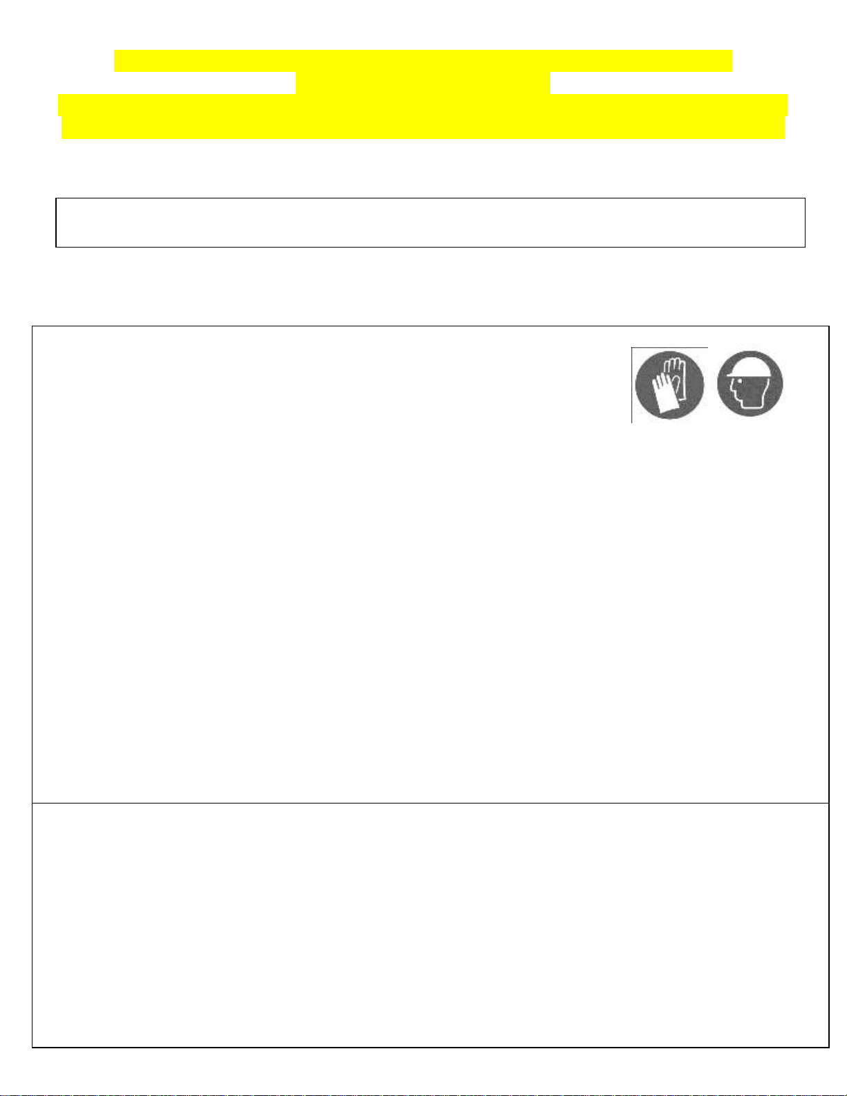
It is recommended to wear safety gloves, safety glasses, and hard hats for installation.
Do not hang from, climb on, or stand on the structure or roof.
Before assembly, read instructions and check that all parts are present in the boxes. If any parts are missing, refer to warranty
information.
A 6ft (1.8m) stepladder, Phillips screwdriver, tape measure, level, mallet, and a tarp to place parts on will be required for assembly
(not included).
Remove top protective film from roof panels prior to assembly; DO NOT remove bottom protective film until ready to insert roof
panels, so as to identify which side is on top.
ANCHORING INSTRUCTIONS:
Proper anchoring of the frame to the base and the wall is required for safety.
Any structure not anchored securely has the potential to fly away during high wind causing damage and safety hazard.
How the item is anchored, and the hardware and tools required, will vary based upon the set-up location and are not provided.
Please check with your local hardware store if for the appropriate anchors for your surface.
Do not anchor to pavers / pavement slabs because they are not a solid foundation.
Periodically check the anchors to ensure they remain secure
CARE AND MAINTENANCE:
In case of a defective or damaged part, or for any other questions concerning the product, please contact the manufacturer directly.
Please have the parts list and part numbers on hand when ordering or requesting replacement parts.
ROOF PANELS:
Gently clean with an environmentally-friendly soap solution and water using a sponge or washcloth.
Do not use abrasive materials, wire brushes, chemicals, harsh cleaners, or bleach.
Rinse using a garden hose and air dry. If removed, ensure thoroughly dry prior to storage.
Do not use pressure washer.
STRUCTURE:
Gently clean with an environmentally-friendly soap solution and water using a sponge or washcloth.
Do not use abrasive materials, wire brushes, chemicals, harsh cleaners, or bleach.
Rinse using a garden hose and air dry.
Do not use pressure washer.
If there are nicks, chips, and/or scratches see the part # of the paint in the parts list to obtain a matching touch-up paint.
FOR FUTURE REFERENCE,
TAKE PICTURES OF ALL SIX SIDES OF EACH OF THE BOXES UPON RECEIPT.
PLEASE VERIFY THE CONTENT OF EACH BOX AGAINST THE LIST OF PARTS
12ft x 16ft / 3.66m x 4.88m GAZEBO
Instruction Manual
IMPORTANT: RETAIN FOR FUTURE REFERENCE, READ CAREFULLY
For assistance with assembly, installation, parts, or customer service, contact Gazebo Penguin Customer
Service Department at the numbers listed below (English & French, Mon-Fri 8:00 AM to 4:00 PM EST):
Montreal: (514) 276-3485 Elsewhere in Canada and the US: 1-800-737-7174
ZZZ-205.43226MR.0705-21.GP.EN.doc WEB VERSION 2

MAINTENANCE NOTES
1. In case of a defective or damaged part, or for any other questions concerning the product, please contact the
manufacturer directly.
2. Please have the parts list and part numbers on hand when ordering or requesting replacement parts.
3. The product should not be installed adjacent to trees or a sloped roof. Snow and ice may slide onto the roof and cause it
to collapse.
4. While the product is designed to stay assembled year long, the roof must be kept free of accumulation of snow.
ONE YEAR LIMITED WARRANTY
This product has been designed and manufactured to meet the highest standards of quality and durability. Subject to
the Conditions for Exercising the Warranty and the Limitations on the Warranty set forth below, it is warranted to be free
of material and manufacturing defects for a period of one year from the date of purchase. Missing and damage due to
transportation is not covered by the manufacture warranty. Should the product become damaged, or the warranty period
has expired, please contact Gazebo Penguin Customer Service Department for a complete schedule of replacement
parts and prices.
CONDITIONS FOR EXERCISING THE WARRANTY
The warranty only applies to the original purchaser with the bill.
In order to properly exercise your warranty, please comply with the following:
Carefully inspect the contents of the carton for missing or damaged components. Should you discover damaged
or missing parts, do not return the product to the place of purchase, but contact Gazebo Penguin Customer
Service Department at the numbers listed below:
Montreal: (514) 276-3485
Elsewhere: 1-800-737-7174
You can also find a claim form to fill out online:
https://abrispenguin.com/assemblyinstructions/
NOTE: Damages/missing parts must be reported within 30 days of delivery. If claimed after your request might
be rejected.
LIMITATIONS ON THE WARRANTY
1. The product is not warranted against damages due to vandalism, abuse, falling or thrown objects, or accumulation of
snow.
2. The product is not warranted against damages due to extreme weather conditions, such as thunderstorms, hail, strong
wind or snow storms, or any other acts of God.
3. Leaking due to heavy rain may happen, please refer to the instruction manual for window positions and information on
how to evacuate the water.
4. The product is only warranted in the event it is installed in accordance with the Gazebo Penguin’s written instructions
enclosed with the product.
5. The product is not warranted in the event it has been improperly anchored.
6. We reserve the right to replace or repair any defective product or parts at our discretion.
7. No change to the unit is allowed. This will void your warranty.
ZZZ-205.43226MR.0705-21.GP.EN.doc WEB VERSION 3

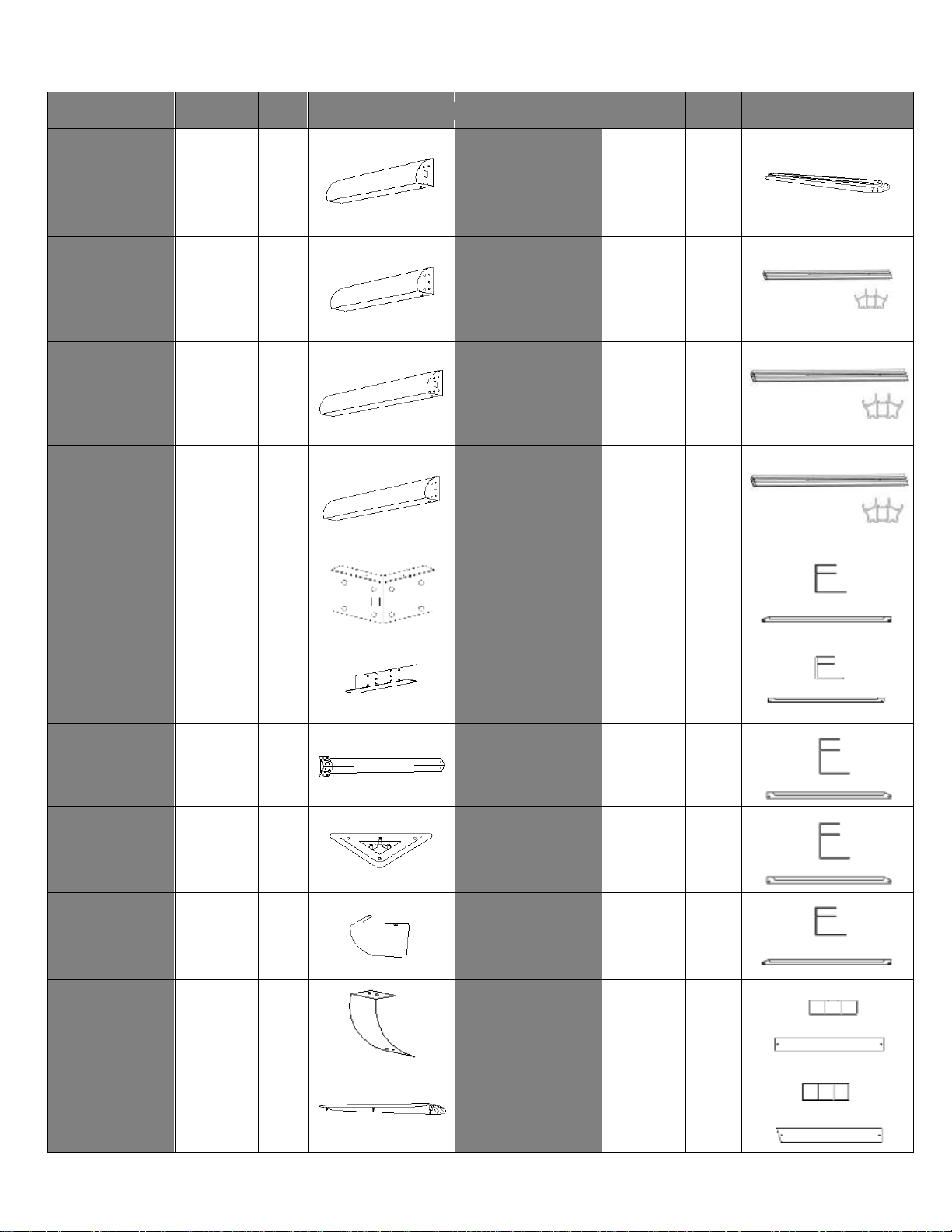
43226MR GAZEBO BROWN (see page 8 for Slate parts)
PART
PACKED
IN BOX
QTY
DIAGRAM
PART
PACKED
IN BOX
QTY
DIAGRAM
(11-626-22)
65 ½”
TOP LEFT
BEAM
A
3
2
(20-042-22)
85 ½ ”
CENTRAL
HUB
L
4
1
(11-627-22)
65 ½”
TOP RIGHT
BEAM
B
3
2
(20-039-22)
92 5/8”
ROOF
RAFTER
L1
4
4
(11-688-22)
91”
TOP LEFT
BEAM
C
3
2
(20-014-22)
60 3/8”
ROOF
RAFTER
L2
4
2
(11-689-22)
91”
TOP RIGHT
BEAM
D
3
2
(20-036-22)
73 3/4”
ROOF
RAFTER
L3
4
8
(11-628-22)
CORNER
PLATE
E
3
4
(20-072-22)
FINISHING BAR
M
4
2
(11-629-22)
CENTER
PLATE
F
3
4
(20-016-22)
FINISHING BAR
M1
4
6
(11-630-22)
81 ½”
LEG
G
3
4
(20-037-22)
FINISHING BAR
M2
4
2
(11-631-22)
FOOT
PLATE
H
3
4
(20-038-22)
FINISHING BAR
M3
4
2
(11-632-22)
CORNER
COVER
I
3
4
(20-073-22)
FINISHING BAR
M4
4
2
(11-633-22)
MIDDLE
COVER
J
3
4
(20-019-22)
SOLIDIFYING
BAR
N2
4
6
(11-690-22)
88”
TOP CAP
K
4
1
(20-031-22)
SOLIDIFYING
BAR
N3
4
2
ZZZ-205.43226MR.0705-21.GP.EN.doc WEB VERSION 4

PART
PACKED
IN BOX
QTY
DIAGRAM
PART
PACKED
IN BOX
QTY
DIAGRAM
(20-032-22)
SOLIDIFYING
BAR
N4
4
2
(20-060-22)
SOLIDIFYING
BAR
BRACKET
P2
4
4
(20-034-22)
SOLIDIFYING
BAR
N6
4
2
(20-070-22)
55 ¼”
RIGHT
FLASHING
Q
4
4
(20-035-22)
SOLIDIFYING
BAR
N7
4
2
(17-053-22)
FINISHING
END
Q1
4
8
(12-030-22)
MOUNTING
BRACKET
O
4
4
(19-097-22)
CORNER
BRACKET
Q2
4
4
(20-012-22)
60 3/8”
COVER
ROOF BAR
O1
4
2
(20-071-22)
55 ¼” LEFT
FLASHING
R
4
4
(20-040-22)
73 3/4”
COVER
ROOF BAR
O2
4
8
(20-074-22)
26 3/4 ”
CENTER
FLASHING
S-1
4
2
(20-041-22)
92 5/8”
COVER
ROOF BAR
O3
4
4
(20-076-22)
76 ½ ”
CENTER
FLASHING
S-3
4
2
(12-031-22)
MOUNTING
BRACKET
P
4
10
(11-692-22)
86”
CURTAIN RAIL
16’ SIDE
T
4
4
(18-067-22)
SOLIDIFYING
BAR
BRACKET
P1
4
10
(11-641-22)
60 1/2 ”
CURTAIN RAIL
12’ SIDE
U
4
4
ZZZ-205.43226MR.0705-21.GP.EN.doc WEB VERSION 5

PART
PACKED
IN BOX
QTY
DIAGRAM
PART
PACKED
IN BOX
QTY
DIAGRAM
(20-023-22)
LEFT LOWER
ROOFPANEL,
16’ SIDE
V2
2
2
(20-0230-22)
RIGHT UPPER
ROOF PANEL,
12’ SIDE
X5
1
2
(20-024-22)
RIGHT LOWER
ROOF PANEL,
16’ SIDE
V3
2
2
(08-158-22)
BOLT
Pp
3
264
(M6x16mm)
(08-156-22)
SCREW
Qq
3
126
(M4x16mm)
(20-025-22)
LEFT LOWER
ROOF PANEL,
12’ SIDE
V4
2
2
(08-167-22)
SCREW
Rr
3
12
(M6x63.5mm)
(20-026-22)
LEFT LOWER
ROOF PANEL,
12’ SIDE
V5
2
2
(08-193-22)
PLASTIC
PLUG
Ss
3
12
(20-022-22)
MIDDLE
LOWER
ROOF PANEL
25”X40”
W1
1
6
(08-187-22)
WASHER
Tt
3
16
(M6)
(20-028-22)
MIDDLE
UPPER ROOF
PANEL
25”X36.5”
Y1
1
6
(11-697-22)
CURTAIN RAIL
CAP
Uu
3
8
(20-027-22)
LEFT UPPER
ROOF PANEL,
16’ SIDE
X2
1
2
(08-189-22)
ACORN NUT
Vv
3
4
(20-024-22)
RIGHT UPPER
ROOF PANEL,
16’ SIDE
X3
1
2
(11-693-22)
SCREEN/
MOUSTIQUAIRE
Ww
4
2
Left
2
Right
(20-029-22)
LEFT UPPER
ROOF PANEL,
12’ SIDE
X4
1
2
(11-694-22)
PRIVACY
CURTAIN
Xx
4
2
Left
2
Right
ZZZ-205.43226MR.0705-21.GP.EN.doc WEB VERSION 6

PART
PACKED
IN BOX
QTY
DIAGRAM
*NOT INCLUDED IN THE BOX
(16-118-22)
SCREW
M6x36
Oo1
3
62
DESCRIPTION
COLOUR
PART #
SPRAY PAINT
BROWN
11-726
(11-705-22)
CURTAIN
HOOKS
3
112
PAINT PEN
18-184
(08-182)
10 mm KEY
3
1
ZZZ-205.43226MR.0705-21.GP.EN.doc WEB VERSION 7
43226MR GAZEBO SLATE
PART
PACKED
IN BOX
QTY
DIAGRAM
PART
PACKED
IN BOX
QTY
DIAGRAM
(11-626-32)
65 ½”
TOP LEFT
BEAM
A
3
2
(20-042-32)
85 ½ ”
CENTRAL
HUB
L
4
1
(11-627-32)
65 ½”
TOP RIGHT
BEAM
B
3
2
(20-039-32)
92 5/8”
ROOF
RAFTER
L1
4
4
(11-688-32)
91”
TOP LEFT
BEAM
C
3
2
(20-014-32)
60 3/8”
ROOF
RAFTER
L2
4
2
(11-689-32)
91”
TOP RIGHT
BEAM
D
3
2
(20-036-32)
73 3/4”
ROOF
RAFTER
L3
4
8
(11-628-32)
CORNER
PLATE
E
3
4
(20-072-32)
FINISHING BAR
M
4
2
(11-629-32)
CENTER
PLATE
F
3
4
(20-016-32)
FINISHING BAR
M1
4
6
(11-630-32)
81 ½”
LEG
G
3
4
(20-037-32)
FINISHING BAR
M2
4
2
(11-631-32)
FOOT
PLATE
H
3
4
(20-038-32)
FINISHING BAR
M3
4
2
(11-632-32)
CORNER
COVER
I
3
4
(20-073-32)
FINISHING BAR
M4
4
2
(11-633-32)
MIDDLE
COVER
J
3
4
(20-019-32)
SOLIDIFYING
BAR
N2
4
6
(11-690-32)
88”
TOP CAP
K
4
1
(20-031-32)
SOLIDIFYING
BAR
N3
4
2
ZZZ-205.43226MR.0705-21.GP.EN.doc WEB VERSION 8

PART
PACKED
IN BOX
QTY
DIAGRAM
PART
PACKED
IN BOX
QTY
DIAGRAM
(20-032-32)
SOLIDIFYING
BAR
N4
4
2
(20-060-32)
SOLIDIFYING
BAR
BRACKET
P2
4
4
(20-034-32)
SOLIDIFYING
BAR
N6
4
2
(20-070-32)
55 ¼”
RIGHT
FLASHING
Q
4
4
(20-035-32)
SOLIDIFYING
BAR
N7
4
2
(17-053-32)
FINISHING
END
Q1
4
8
(12-030-32)
MOUNTING
BRACKET
O
4
4
(19-097-32)
CORNER
BRACKET
Q2
4
4
(20-012-32)
60 3/8”
COVER
ROOF BAR
O1
4
2
(20-071-32)
55 ¼” LEFT
FLASHING
R
4
4
(20-040-32)
73 3/4”
COVER
ROOF BAR
O2
4
8
(20-074-32)
26 3/4 ”
CENTER
FLASHING
S-1
4
2
(20-041-32)
92 5/8”
COVER
ROOF BAR
O3
4
4
(20-076-32)
76 ½ ”
CENTER
FLASHING
S-3
4
2
(12-031-32)
MOUNTING
BRACKET
P
4
10
(11-692-32)
86”
CURTAIN RAIL
16’ SIDE
T
4
4
(18-067-32)
SOLIDIFYING
BAR
BRACKET
P1
4
10
(11-641-32)
60 1/2 ”
CURTAIN RAIL
12’ SIDE
U
4
4
ZZZ-205.43226MR.0705-21.GP.EN.doc WEB VERSION 9

PART
PACKED
IN BOX
QTY
DIAGRAM
PART
PACKED
IN BOX
QTY
DIAGRAM
(20-023-32)
LEFT LOWER
ROOFPANEL,
16’ SIDE
V2
2
2
(20-0230-32)
RIGHT UPPER
ROOF PANEL,
12’ SIDE
X5
1
2
(20-024-32)
RIGHT LOWER
ROOF PANEL,
16’ SIDE
V3
2
2
(08-158-32)
BOLT
Pp
3
264
(M6x16mm)
(08-156-32)
SCREW
Qq
3
126
(M4x16mm)
(20-025-32)
LEFT LOWER
ROOF PANEL,
12’ SIDE
V4
2
2
(08-167-32)
SCREW
Rr
3
12
(M6x63.5mm)
(20-026-32)
LEFT LOWER
ROOF PANEL,
12’ SIDE
V5
2
2
(08-193-32)
PLASTIC
PLUG
Ss
3
12
(20-022-32)
MIDDLE
LOWER
ROOF PANEL
25”X40”
W1
1
6
(08-187-32)
WASHER
Tt
3
16
(M6)
(20-028-32)
MIDDLE
UPPER ROOF
PANEL
25”X36.5”
Y1
1
6
(11-697-32)
CURTAIN RAIL
CAP
Uu
3
8
(20-027-32)
LEFT UPPER
ROOF PANEL,
16’ SIDE
X2
1
2
(08-189-32)
ACORN NUT
Vv
3
4
(20-024-32)
RIGHT UPPER
ROOF PANEL,
16’ SIDE
X3
1
2
(11-693-32)
SCREEN/
MOUSTIQUAIRE
Ww
4
2
Left
2
Right
(20-029-32)
LEFT UPPER
ROOF PANEL,
12’ SIDE
X4
1
2
(11-694-32)
PRIVACY
CURTAIN
Xx
4
2
Left
2
Right
ZZZ-205.43226MR.0705-21.GP.EN.doc WEB VERSION 10

PART
PACKED
IN BOX
QTY
DIAGRAM
*NOT INCLUDED IN THE BOX
(16-118-32)
SCREW
M6x36
Oo1
3
62
DESCRIPTION
COLOUR
PART #
SPRAY PAINT
SLATE
18-125
(11-705-32)
CURTAIN
HOOKS
3
112
PAINT PEN
18-126
(08-182)
10 mm KEY
3
1
ZZZ-205.43226MR.0705-21.GP.EN.doc WEB VERSION 11

Before You Assemble the Gazebo
Please don't destroy boxes until completely assembled.
For future reference, take pictures of all six sides of each of the boxes upon receipt.
Please verify the content of each box against the list of parts.
It is important that this gazebo be anchored on a solid base with the provided screws.
Otherwise, please ensure that you use anchors sufficient for your surface.
The gazebo should not be installed adjacent to trees or a sloped roof. Snow and ice may slide
onto the gazebo and cause it to collapse.
Tools required (not provided)
6ft (1.8m) Stepladder
Robinson #2 Screwdriver
Mallet
Tarp or protective material for placing
parts on during assembly
Step 1:
1. Assemble Beams “A” and “B” using Center Plate “F”, by sliding it inside the beams and
securely tighten with 10 Bolts “Pp”. Repeat with Beams “C” and “D”, also using Center Plate “F”.
2. Lay out the assembled Beams in a rectangle and join at each corner with a Corner Plate “E”,
by sliding it inside the beams and tighten it with 4 Bolts “Pp” tightly and hand fasten remaining
4 Bolts in pink. – see image on pg. 9
Tape Measure
Leveling Shim
Safety Gloves & Glasses
ZZZ-205.43226MR.0705-21.GP.EN.doc WEB VERSION 12

ZZZ-205.43226MR.0705-21.GP.EN.doc WEB VERSION 13

Step 2:
1. For each Leg “G”, attach Foot Plate “H” using 3 Bolts “Pp”.
Step 3:
1. Unscrew 4 Pp Bolts as shown below, have someone lift the Beam assembly and attach each
Leg “G” into a Corner, again securing each using 4 Bolts “Pp”.
2. Repeat until all four Legs are in place.
ZZZ-205.43226MR.0705-21.GP.EN.doc WEB VERSION 14

Step 4:
1. Install Middle Cover “J” at each of the 4 beam junctions, using 4 Screws “Qq” each.
2. Install Corner Cover “I” at each of the corners, using 4 Screws “Qq” each.
ZZZ-205.43226MR.0705-21.GP.EN.doc WEB VERSION 15

Step 5:
1. Screw Mounting Bracket (O) to Rafter (L1) and Bracket (P) to Rafter (L2, L3) using the second
last insert from under the rafter using Bolt (Pp).
2. Attach Roof Rafters (L1, L2, L3) to the Central Hub (L) using Bolt (Pp).
3. Use Screws (Qq) to affix the Rafters (L2, L3) onto the top of the structure going through the
Mounting Brackets (P) attached to the Rafters.
4. Then, use Bolts (Pp) to affix the Rafters (L1) onto the top of the structure going through the
Mounting Brackets (O) attached to the Rafters.
Note: Rafters must be affixed where hole screws are closer to the center.
ZZZ-205.43226MR.0705-21.GP.EN.doc WEB VERSION 16

Pp
S-1
Step 6:
1. Install the Flashings “Q”,
“R”, “S”, and “S-1” onto the
beam assembly, using
screws “Qq” on the inside.
The notched end of a
flashing will always go in a
corner of the gazebo.
Step 7:
1. Install the curtain rails “T” and “U” on the inside of the beam assembly using bolts “Pp”.
ZZZ-205.43226MR.0705-21.GP.EN.doc WEB VERSION 17

Step 8:
1. Place Finishing Bars (M, M1, M2, M3, M4) next to each other and align the pre-drilled holes in
each bar one on top of the other.
2. Place Finishing End & Corner Bracket (Q1, Q2) over the aligned holes and secure with Bolts
(Pp).
3. Repeat process with all Finishing Bars as illustrated.
4. In order to finish the installation of the last Finishing Bar (M) you have to unscrew the first Bolts
(Pp) at your starting point and place (Q1, Q2) then re-install the Bolt (Pp).
ZZZ-205.43226MR.0705-21.GP.EN.doc WEB VERSION 18

Step 9:
1. From the inside of the solarium, install the Solidifying Bar (N2, N3, N4, N6, N7) as illustrated
using the Bolts (Pp).
2. Each Bolt (Pp) must be inserted into the inserts of the Rafters.
ZZZ-205.43226MR.0705-21.GP.EN.doc WEB VERSION 19

Step 10:
W1/V2/V3/V4/V5
M1/M2/M3
V2
W1
W1
W1
V3
V5
V4
V3
W1
W1
W1
V2
V4
V5
TOP VIEW
Y1
Install the Bottom Roof Panels (W1, V2, V3, V4, V5) by sliding them onto Finishing Bars (M, M1, M2,
M3, M4).
Step 11:
Install First Upper Roof Panel (Y1) by sliding it on top of Rafters (L1, L2, L3).
Note: Roof Panel must be held in place until it is secured with the Cover Roof Bar.
ZZZ-205.43226MR.0705-21.GP.EN.doc WEB VERSION 20

Step 12:
L1/L2/L3
O1/O2/O3
Oo1
1. Once the installation of the panel is complete, install a Cover Roof Bar (O1, O2, O3) onto the
Rafter (L1, L2, L3) with the help of bolts (Oo1).
2. Place Cover Roof Bar on top of Rafter, but do not completely screw it until both panels
connected to the Rafter are placed.
ZZZ-205.43226MR.0705-21.GP.EN.doc WEB VERSION 21

Step 13:
Y1
X3
1. Install the next upper roof panel (X3) by sliding it on top of roof rafters (L1, L2, L3) then secure.
2. Continue to install the other panels one at the time until the last section.
ZZZ-205.43226MR.0705-21.GP.EN.doc WEB VERSION 22

Step 14:
Before installing last Upper Roof Panel, put Cap (K) on top of the Central Hub (L)
ZZZ-205.43226MR.0705-21.GP.EN.doc WEB VERSION 23

Step 15:
TOP VIEW
Y1
Y1
Y1
Y1
Y1
Y1
X2
X2
X3
X4
X5
X3
X4
X5
Install the last Upper Roof Panel (Y1).
ZZZ-205.43226MR.0705-21.GP.EN.doc WEB VERSION 24

Step 16:
O1/O2/O3
L1/L2/L3
Oo1
Once the last Roof Panel is installed, screw last Cover Roof Bar (O1, O2, O3) to the roof
bars (L1, L2, L3) with bolt (Oo1).
ZZZ-205.43226MR.0705-21.GP.EN.doc WEB VERSION 25

Step 17:
Use Nut (Vv) to affix Top Cap (K) to the Central Hub (L).
ZZZ-205.43226MR.0705-21.GP.EN.doc WEB VERSION 26

Step 18:
1. Secure each Foot Plate into the ground using Screws “Rr” and Washers “Tt”.
2. Use lag Shields (Ss) if needed for harder surfaces.
Step 19:
1. Install the Screen Curtains “Ww” in the interior groove of the curtain rails, using the provided
Hooks. Install the Privacy Curtains “Xx” in the Exterior Groove of the rails. The Curtains and
Screen Panels facing diagonally to each other will be same.
2. Once the Hooks are in, use Curtain Rail Caps “Uu” to close ends of Curtain Rails.
ZZZ-205.43226MR.0705-21.GP.EN.doc WEB VERSION 27

NOTE: The Dimensions Are Approximate.
ZZZ-205.43226MR.0705-21.GP.EN.doc WEB VERSION 28
 Loading...