


LIMITED LIABILITY COMPANY "AVTOZAVOD "GAZ"
(LLC "AVTOZAVOD GAZ")
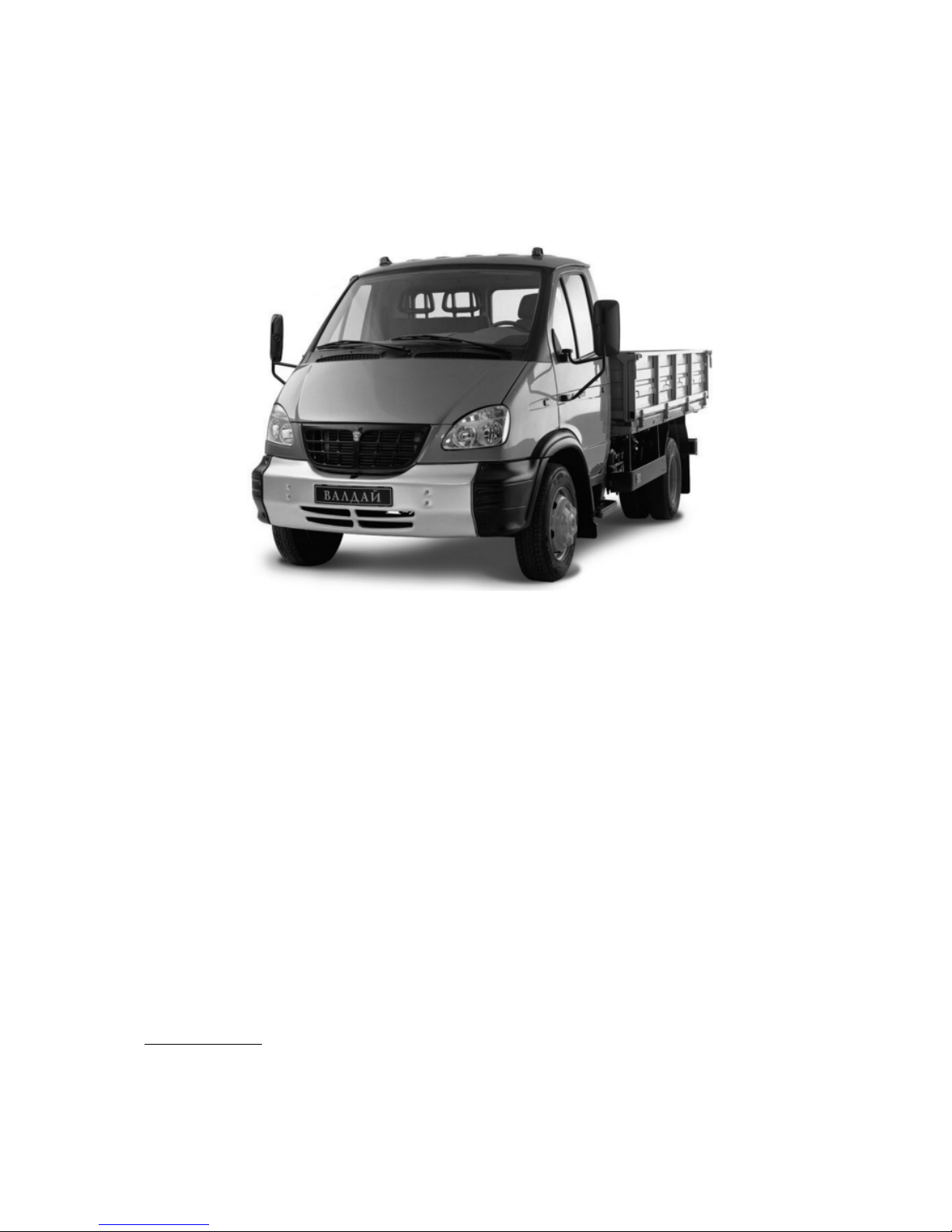
VALDAI
VEHICLES FAMILY
OPERATING INSTRUCTIONS
331043902111 ИЭ
RUSSIA
NIZHNIY NOVGOROD
2
Introduction
"VALDAI" vehicles are intended for transportation of goods over differ
ent roads in moderate climate conditions at the ambient air temperature from
plus 45° C to minus 45° C.
1) Service Book for 'VALDAI' vehicle is attached to this Operating Instructions.
"VALDAI" vehicles family presented in this Operating Instructions com
prises the following models:
GAZ33104 vehicle — 4x2 type with threeseat cabin.
GAZ331041 vehicle — 4x2 type with threeseat cabin and extended wheel
base.
GAZ331043 vehicle — 4x2 type with sixseat cabin and extended wheel
base.
The manufacturer reserves the right to constantly alter its vehicle design,
therefore some units and parts may slightly differ from those described in this
Operating Instructions.
You can surely expect reliable operation of the vehicle provided you ob
serve maintenance schedule specified in this Operating Instructions and Serv
ice Book1).
3
1.VEHICLE IDENTIFICATION DATA
Identification number of the vehicle (VIN) and identification numbers of
cabin or allmetal body, engine and cargo body vehicle chassis refer to the ve
hicle identification data.
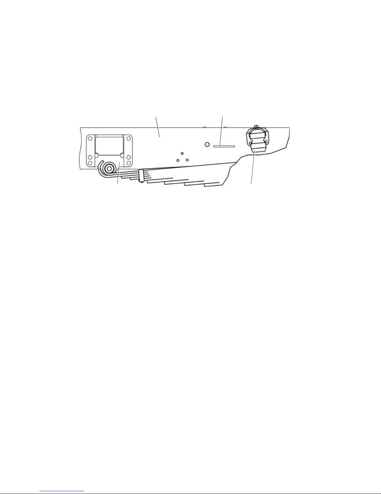
Vehicle Identification Number (VIN) appears on the right frame side
member before the rear spring front bracket (Fig.1.1).
Fig. 1.1. Location of VIN or Chassis Number:
1 — rear spring rear bracket; 2 — frame side member, right; 3 — location of identification number;
4 — rubber restraint cushion
Example of Vehicle Identification Number:
X96 33104050000125, where:
X96 — manufacturer international identification code,
331040 — vehicle index,
5 — model year code,
0000125 — vehicle serial number.
Model year is a period equal on the average to calendar year during which
the vehicles with identical design features are being manufactured.
Chassis identification number is marked on the right side member of the
frame of cargo body vehicles intended for supplying to other plants for manu
facturing special vehicles (Fig. 1.1).
Example of Chassis Number:
33104050000125, where:
331040 — chassis index,
5 — model year code,
0000125 — chassis order number.
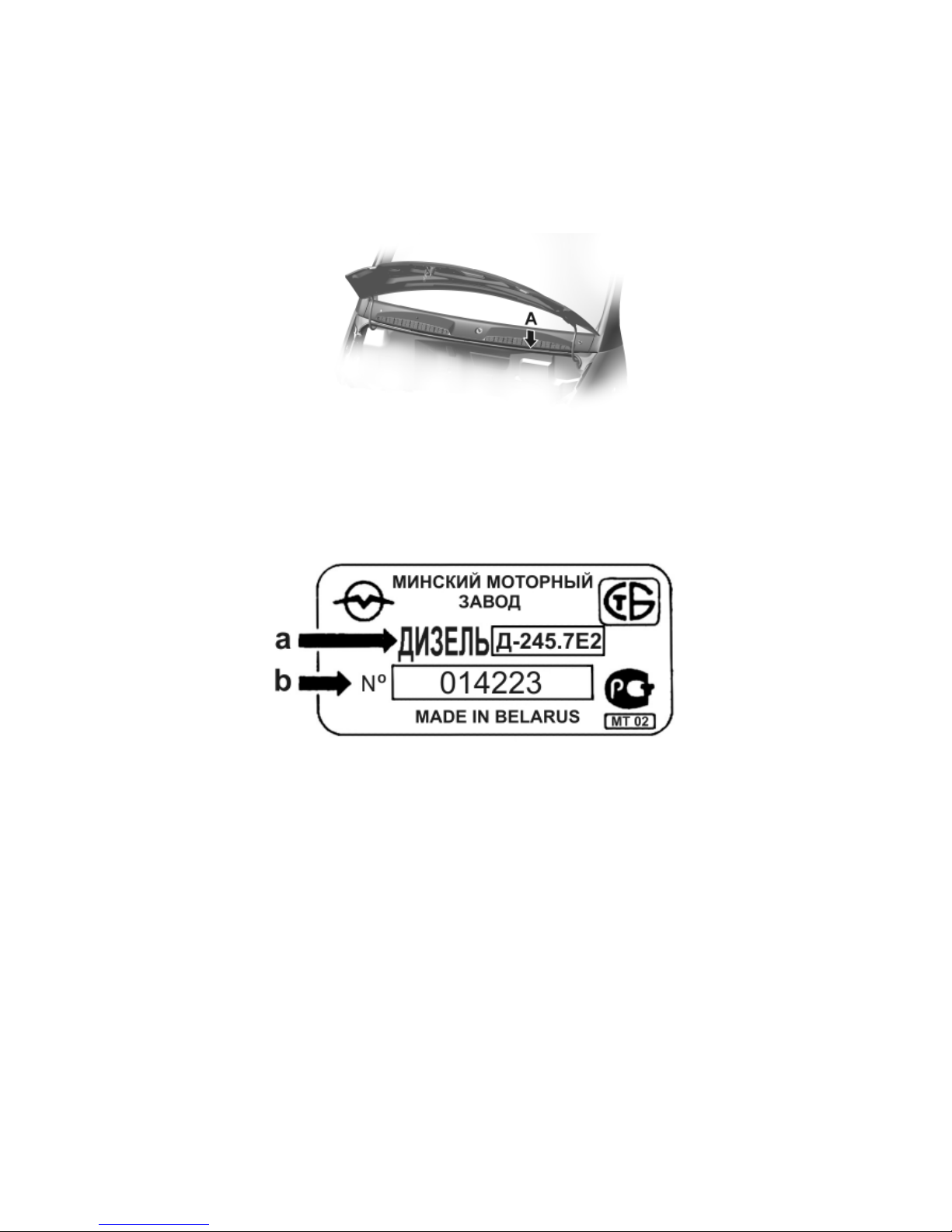
Cab identification number is located under the hood on the front outer
panel, on the left in direction of vehicle movement (see Fig. 1.2, arrow "A"
view).
1 4
3
2
4
Example of Cab (Body) Number:
33104050000125, where:
331040 — cabin index
5 — model year code,
0000125 — cabin serial number.
Fig. 1.2. A — Location of Cab Identification Number
Д245.7 E2 engine number is stamped on the nameplate (Fig. 1.3) located
on the cylinder block in the middle portion on the righthand side.
Fig. 1.3. Д245.7 E2 Engine Nameplate
The nameplate contains the following data:
a — engine index;
b — engine serial number
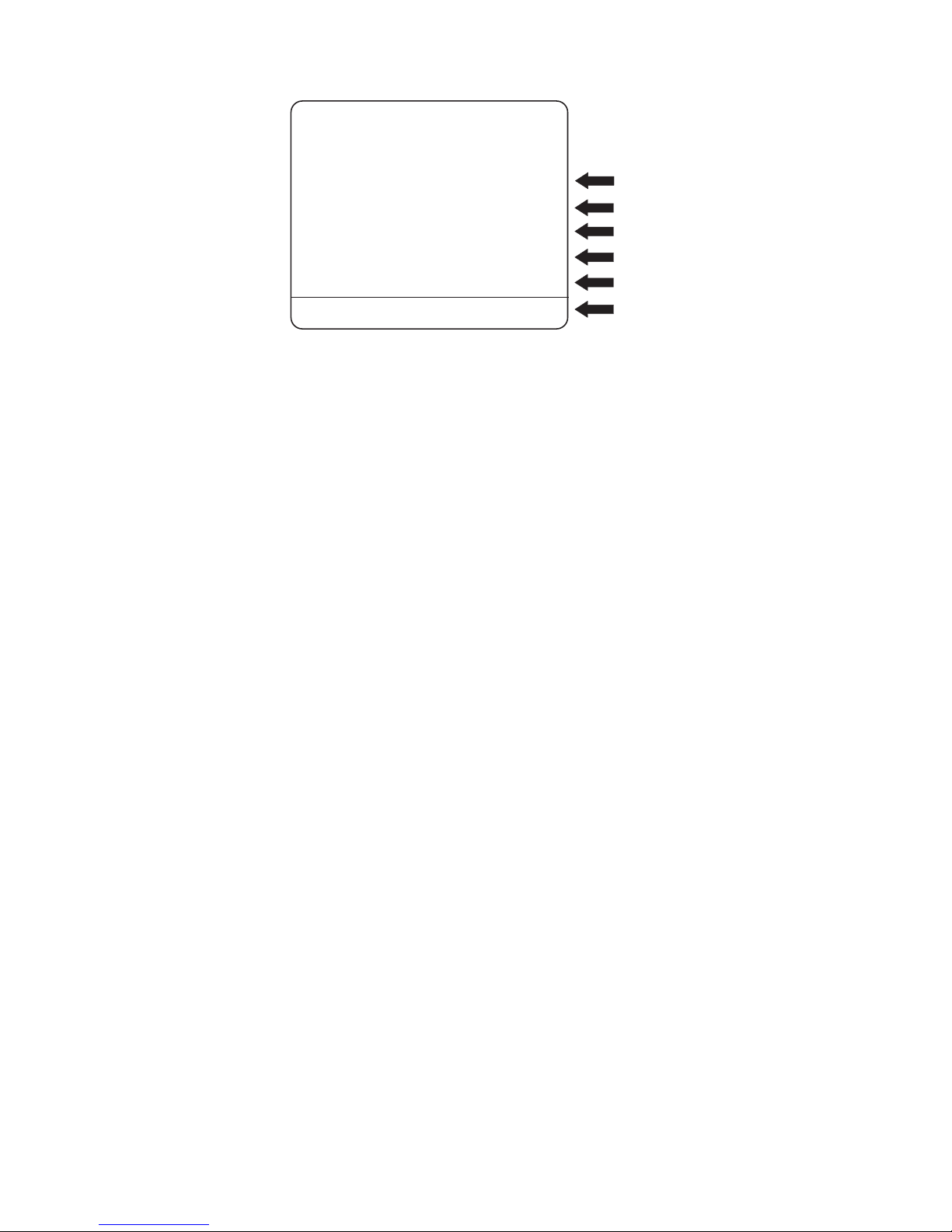
Vehicle identification data also appear on manufacture's plate (Fig. 1.4)
located on the rear pillar of the cab right door.
Chassis, cab and engine numbers refer to the identification data of chassis
and special configuration vehicles for supplying to the other plants for making
their own special vehicles having their own index. Nameplate "GAZ" is not
installed and vehicle identification number does not appear on chassis and the
above vehicles.
5
Fig. 1.4. Manufacture's Plate with Vehicle Identification Data, where:
a — vehicle identification number;
b — gross vehicle weight;
c — gross vehicle weight with trailer;
d — maximum front axle weight;
e — maximum rear axle weight;
f — engine index
2. USEFUL HINTS
1. Procedure of engine starting is described in section 6.2. "Engine Start
ing and Stopping".
After cold engine starting do not run it immediately at high speed because
cold oil passes slowly to rubbing surfaces and they may be got damaged at the
engine high speed.
2. The engine efficient performance and its wear mostly depend on engine
operating temperature. It is necessary to maintain coolant temperature within
the limits of 80–95° C. At the ambient air temperature of 5° C and below in
stall cold weather radiator cover.
3. Do not operate the starter continuously for more than 15 seconds. For
the second attempt of engine starting, allow not less than 30 seconds. Not more
than three engine starting attempts are permissible. Should the engine fail to
fire after these attempts, check the starter power circuits, the starter itself, the
engine fuel system and the storage battery for good condition.
Never move the vehicle using the starter and turn on the starter with the
running engine.
4. After cold engine starting do not run it at high speed. Warm the engine
up at 10001400 rpm. Never drive the vehicle with cold engine. Coolant tem
perature before starting movement should be not less than 40° C.
X96
Д-245.7Е2
33104050140794
7500 кг
-кг
2400 кг
1-
2-
540 кг0
a
b
c
d
e
f
LLC AUTOMOBILE PLANT GAZ““”
ENGINE

6
5. If the engine has been operated at heavy duty cycle let it run for 3 min
utes at idle speed before stopping to decrease smoothly the temperature of tur
bocharger to avoid its premature damage.
6. To prevent damaging of the gearbox when towing the vehicle, discon
nect the propeller shaft flange from the axle drive. Then fix reliably the dis
connected end of the propeller shaft via a wooden block to the vehicle nearest
frame element.
7. Do not eliminate free axial displacement of steering arm pin ball head as
to drag link because the travel equal to 3,4 mm with the shutdown engine is
required for power steering drive proper operation.
8. To avoid dislocating of relative position of the steering gear and steer
ing wheels, never set out the adjustment of the drag link length (except for the
cases specified in given Operating Instructions).
9. To avoid overheating of power steering drive system, do not run the en
gine for a long time at high speed (more than 30 minutes) when the vehicle is
at parking place.
10. With operating engine do not keep the steering wheel turned as far as
it will go for more than 15 sec. because it may cause damage of the power steer
ing pump. Never start the engine with power steering tank empty or insuffi
cient oil level.
11. When the ambient air temperature is below 35° C fill the power steer
ing system with special liquid (see subsection "Lubrication Chart").
12. Watch out for tightness of air pipelines, cylinders and pneumatic valves.
Break of air tightness reduces braking efficiency.
13. To avoid storage batteries failure, timely switch over regulated volt
age level.
14. If any of the red pilot lamps lights up on the instrument cluster or buzzer
operates on the run, stop the vehicle, detect and eliminate the trouble.
15. The brake pads are to be replaced at service stations only.
3. SAFETY PRECAUTION RULES
Strictly follow the safety precaution rules during vehicle operation.
Never warm up the engine in the enclosed space. The engine exhaust gases
contain toxic end product of fuel combustion, monoxide carbon including (gas
without fume and color), which, when inhaling, causes severe intoxication and
it may even lead to fatal case. It is also not recommended to turn on the pas
senger compartment ventilation at parking place with the operating engine.

7
4. SPECIFICATIONS
4.1. GENERAL DATA
Vehicle model GAZ33104 GAZ331041 GAZ331043
Vehicle type Biaxial, cargo, with rear axle drive
Vehicle capacity, kg:
— with cargo body without canvas top 3605 3445 3150
— with cargo body and with canvas top 3500 3330 3045
Vehicle gross mass, kg 7400 7400 7400
Vehicle kerb mass, kg:
— with cargo body without canvas top 3500 3730 3800
— with cargo body and with canvas top 3605 3845 3905
Overall dimensions, mm
— length 6050 7565 6770
— width (over mirrors) 2643 2643 2643
— height (over cabin, unladen) 2260 2260 2265
— height (over canvas top, unladen) 3060 3060 3060
Wheelbase, mm 3310 4000 4000
Front wheels track, mm 1740 1740 1740
Rear wheels track (between centres of twin tyres),
mm 1701 1701 1701
Ground clearance, fully laden, mm 177 177 177
Minimum turning radius (front outer track), not
more, m 6,4 7,7 7,7
Maximum speed with full load without trailer on
flat, smooth highway, km/h 95 95 95
Fuel consumption1) when running with constant
speed, l/100km:
— 60 km/h 13,5 13,5 13,5
— 80 km/h 18,0 18,0 18,0
Overhang angles (fully laden), deg.:
— front 27 27 27
— rear 14 10 14
Maximum climable gradient for fully laden vehicle,
% (degree) 25 (14) 25 (14) 25 (14)
Cargo body loading height, mm 1070 1070 1070
4.2. ENGINE AND ITS SYSTEMS
Model D245.7 E2
Type Diesel, 4stroke, with turbocharger, with
supercharged air cooling, liquid cooling
Number of cylinders and their arrangement 4, vertical inline
Cylinders firing order 1—3—4—2
Direction of crankshaft rotation right
1) The fuel consumption specified is not considered to be a rate but serve only for determining
of vehicle technical state.

8
Cylinder bore and piston stroke, mm 110x125
Displacement, l 4.75
Compression ratio 17
Rated power, net, kW (h.p.), not less:
at 2400 min1 engine speed 86.7 (117.2)
Maximum torque, net, N•m (kgf•m):
at 13001600 min1 engine speed 413 (42.1)
Minimum engine idle speed, min
1
800
Maximum idle speed limited by governor, min1,
not more 2600
Ventilation system open
Fuel injection pump Inline, 4plunger, valve type, 7732005
(ЯЗТА) with full range rpm governor and
booster fuel pump
Booster fuel pump Plunger type, for manual and automatic
fuel priming
Injectors ЯЗДА 455.111201050, closed type;
injection point pressure 23,5+1.2MPa
(230 kgf/cm2)
Fuel filters:
— coarse filter Gravitation filter with gauze element
— fine filter With paper renewable filter element
Oil system Combined: under pressure and spraying
Oil cooler Fullflow, constantly operating
Oil filter Fullflow, with renewable filter element
Cooling system Liquid, closed, with forced coolant circula
tion, with expansion tank
Supercharging system Gas turbine, with one turbocharger C14
with radial centripetal turbine, centrifugal
compressor and air cooler of supercharging
air of secondary surface type
4.3. TRANSMISSION
Clutch Singleplate, dry, friction type, with torque
vibration damper on driven plate. With di
aphragm pressure spring. With hydraulic
drive
Gearbox Mechanical, 5speed, with constant gear
mesh, with synchromesh unit on II and III,
IV and V gears
transmission ratios:
— 1st gear 6.555
— 2nd gear 3.933
— 3d gear 2.376
— 4th gear 1.442
— 5th gear 1.000
— reverse gear 5.735
Cardan drive Two open type divided propeller shafts,
three universal joints on needle bearings

9
Final drive Bevel, hypoid type
— transmission ratio 3.417
Differential Bevel, geartype
Axle shafts Full floating
4.4. RUNNING GEAR
Frame Stamped, riveted
Wheels Disk type, with 6,00x17,5 rim
Tires Pneumatic, radial, size 215/75R17,5
Front wheel geometry:
— camber Max. 1°
— pivot transverse inclination 8°
— lengthwise inclination of king pin 5°
— toein (of every wheel to vehicle longitudinal
axis) 7"±3"
Springs Four, longitudinal, semielliptic with ad
ditional springs in rear suspension
Shock absorbers Hydraulic, telescopic, dual acting. Mount
ed on the front axle
4.5. STEERING SYSTEM
Type of steering gear Screwball nut
— transmission ratio 19.8 (in the middle position)
Power steering Hydraulic, integrated, built in steering gear.
Power steering pump is a geartype. НШ14
Steering column Height and tilt adjustable
4.6. BRAKE SYSTEM
Service brake system Doublecircuit, with pneumatic drive
Brake gears Disk type
Emergency brake system Each circuit of service brake system
Parking brake system With pneumatic drive of brake chambers
with spring energy accumulators installed
on rear wheel disk brakes
4.7. ELECTRICAL EQUIPMENT
Wiring system Single wire. Negative terminals are connect
ed to vehicle frame
Rated voltage, V 12
Alternator A/C, with builtin voltage regulator and
rectifier block, 1631.370110
Storage battery Two (6CT 110A)
Starter AZS 3385"Искра"
Headlamps 62.371119

10
Turn indicator repeaters 5302.3726000 or 112.03.30.00.00001
Front marker lights 265.3712
Rear lights 7442.3716.00011 or 8502.371601
Side marker light 4472.3731
Headlamp aiming device control unit БУК24 or 281.3769 or 231.3769
Engine control switch 2126370401050 or 2108370401080
Windshield wiper 60.5205 or 70.5205
Windshield washer 1202.5208, 1102.5208
Horns 22.3721/221.3721
4.8. CABIN AND CARGO BODY
Cabin Metal, three— or sixseat
Cargo body Metal, with rear flap and body sides
Cargo body dimensions (inner), mm: GAZ33104 GAZ331041 GAZ331043
— length 3494 5000 3494
— width 2176 2176 2176
— body side height 518 518 518
4.9. MAIN ADJUSTMENT AND CHECKING DATA
Clearance between valve stems and rocking levers
on cold engine, mm
— intake 0,25
— exhaust 0,45
Oil pressure (at oil temperature of 80–85° C), kPa
(kgf/cm2):
— at rated engine speed 2400 min
1
250–350 (2.5–3.5)
— at minimum idle speed 80 (0.8)
Rated engine coolant temperature, °C 80–95
Minimum engine idle speed, min
1
800
Variable voltage, V 13.3–14.9
Fan and alternator belts sag under 4 daN (4 kgf), mm 12–17
Clutch pedal free travel, mm 10–30
Clutch pedal full travel, mm 190
Brake pedal free travel, mm 9–16
Total play of steering wheel in the position corres
ponding to vehicle straightforward run with run
ning engine, deg., not more 101); 25
Tire air pressure, kPa (kgf/cm2)
— front wheels 530
+10
(5.4
+0.1
)
— rear wheels 620
+10
(6.3
+0.1
)
1) For the vehicle within warranty period.
+0,05
–0,10
+0,05
–0,10
11
5. CONTROLS AND INSTRUMENTS
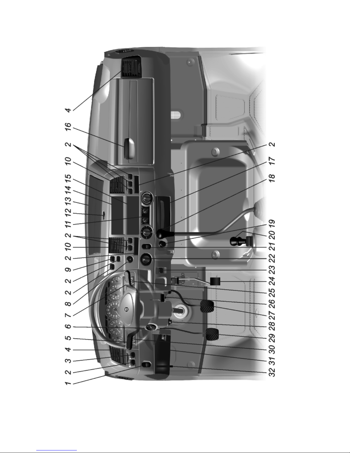
Fig. 5.1. Controls
12
Positions of controls are given in fig. 5.1.
1 — headlamp aiming device control knob depending on vehicle loading
(see subsection 8.5).
2 — plugs.
3 — warning lamps condition checkup switch.
4 — side ventilation grids.
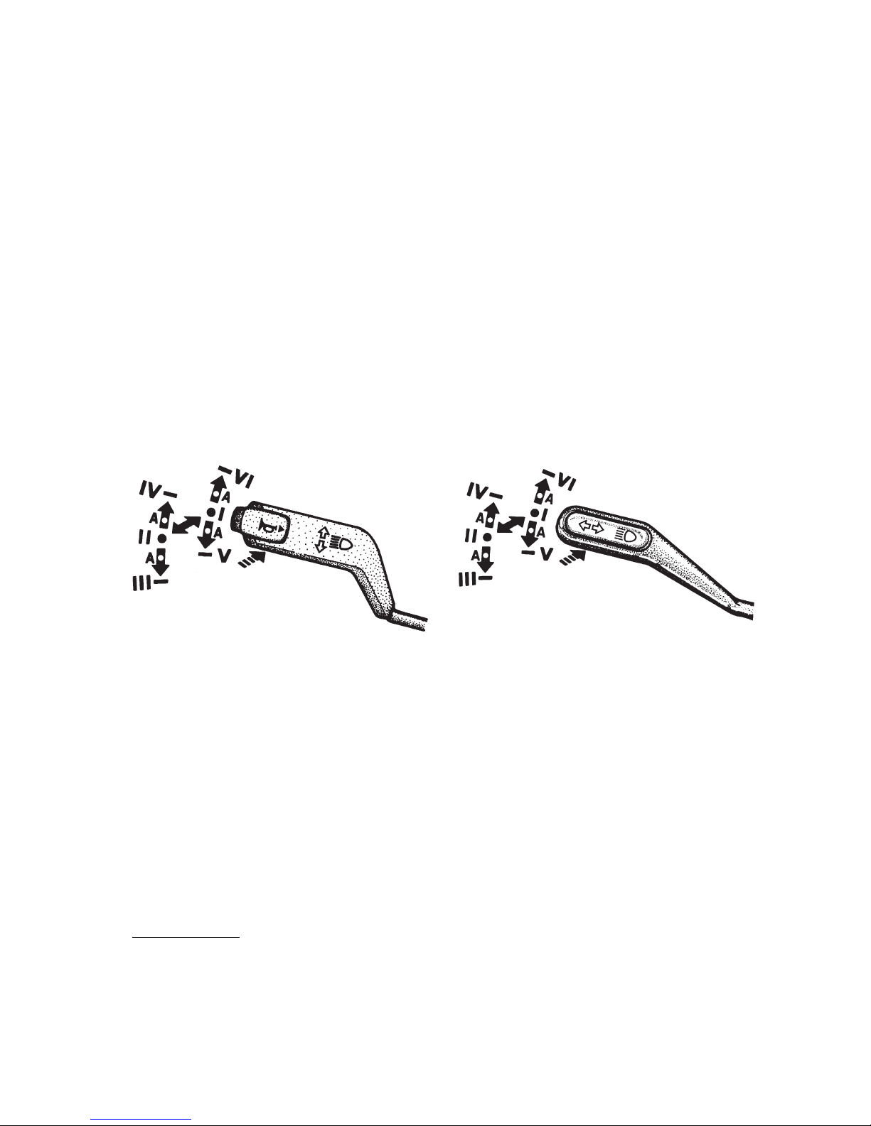
5 — turn indicators, dimmer and horn1) switch lever. The switch lever
has six fixed positions (from I to VI) and four nonfixed positions "A" (fig. 5.2
and 5.3).
If the lever is in position I, and master light switch knob 22 — in position
II, the lower beam is on. When the lever is moved to position II upper beam is
switched on and blue indicator lights up.
Pulling the lever repeatedly from position I along the steering column (non
fixed position) switches on headlamp upper beam for a short time. Depressing
the switch lever button (in any position of the lever) turns on the horn1) (non
fixed position) — see fig. 5.2.
1) On some of the vehicles the horn is switched on by means of windshield wiper and washer
control lever (see Fig. 5.6).
Fig. 5.3. Turn indicator and dimmer
switch lever (without horn)
Fig. 5.2. Turn indicator and dimmer
switch lever (with horn)
To operate turn indicators move the lever from positions I or II up to posi
tions VI or IV (right turn) or down to positions V or III (left turn). A green
warning light comes on flashing on the instrument cluster.
After the turn is completed the switch lever is automatically returned to
position I or II. To switch on turn indicators momentarily shift the switch le
ver to suitable "A" nonfixed position. When released the lever returns to po
sition I or II.
6 — engine control, starter and antitheft device switch.The key posi
tions are given in fig. 5.4:
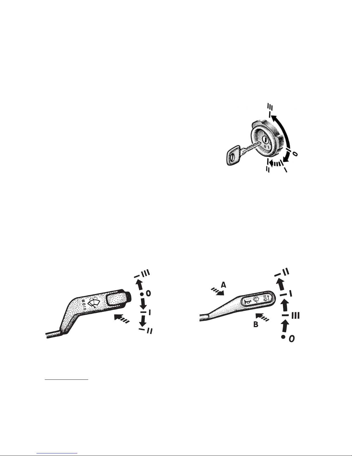
13
0 — all Off, the key cannot be pulled out, antitheft device is not engaged;
I — engine control switch is On; the key cannot be pulled out;
II — engine control switch and starter are On; the key cannot be pulled out;
III — engine control switch is Off; when the key is withdrawn, the anti
theft device is engaged.
To release the antitheft device fit the key, then gently swinging the steer
ing wheel to both sides turn the key to position 0.
Fig. 5.4. Engine control, starter and antitheft
device switch.
7 — windshield wiper, washer and horn 1) switch lever.
The positions of the lever (fig. 5.5 and 5.6):
0 — windshield wiper is OFF;
I — low speed of windshield wiper;
II — high speed of windshield wiper;
III — intermittent operation of windshield wiper.
In case the control lever is not equipped with horn switch (fig. 5.5), to
turn on windshield wiper and washer momentarily pull the lever (in the direc
tion of the arrow) from position 0.
Fig. 5.6. Windshield wiper and
washer lever positions (with horn)
Fig. 5.5. Windshield wiper and
washer lever positions (without horn)
1) On some of the vehicles the horn is turned on by turn indicators and dimmer switch lever
(see Fig. 5.2).
14
In case the control lever is equipped with horn switch (fig. 5.6), to turn on
windshield wiper and washer momentarily push the lever from position 0 in
the direction of arrow "A" and to turn on the horn pull the lever (from any
position) in the direction of arrow "B".
Windshield washer can be also switched on from all lever positions. Wind
shield wiper operates only when the engine control switch is on.
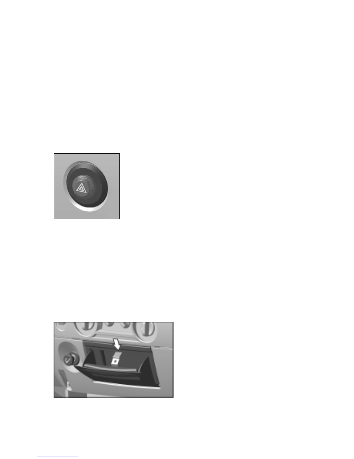
8 — emergency flasher warning system button switch. When in switched
on position all turn indicator bulbs and red bulb inside the button switch
(fig. 5.7) are flashing simultaneously.
Emergency flasher warning system should be switched on in case of vehi
cle accidental stop in order to inform other drivers and maintenance services
about stationary vehicle on the roadway.
Fig. 5.7. Emergency flasher warning system button
switch.
9 — rear row seats dome lamp switch of the cab (for vehicles with two
rows of seats).
10 — central ventilation grids.
11 — heating and ventilation control panel.
12 — lock button for documents box cover.
13 — documents compartment cover.
14 — space for radio set/cassette player.
15 — plug.
16 — glove box lock handle.
17 — ashtray. Removal of ashtray is shown in fig. 5.8.
Fig. 5.8. Ashtray
15
To empty the ashtray pull it, push spring catcher upwards and remove the
ashtray from its slot. Fit the ashtray back liftingup the spring catcher.
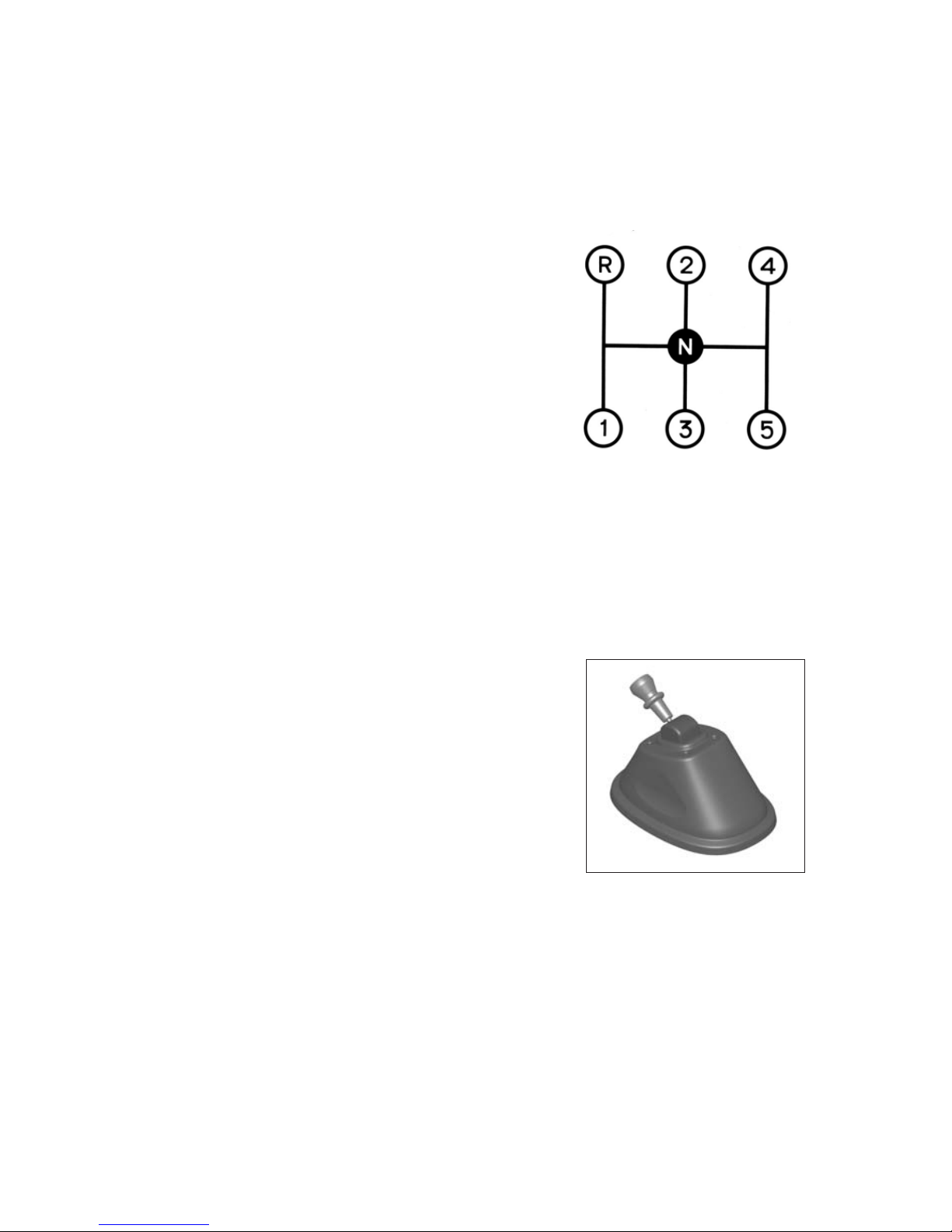
18 — gearbox lever.
Engage reverse gear only after full stop of the vehicle. When reverse gear
is engaged the backing light goes on in the tail lamps.
Fig.5.9. Changeover layout:
19 — cigarette lighter. To use the lighter, push its handle and release it.
The lighter kickout with a click means that the coil is hot. Do not reuse the
lighter sooner that in 30 s.
20 — parking brake lever. For braking the vehicle pull the brake control
lever up. If the engine control switch is on warning lamp 9 (fig. 5.14) is flash
ing on the instrument cluster. For releasing the brake pull up the control lever
lock coupling. With the brake released the warning lamp goes out.
Fig. 5.10. Parking brake lever
21 — instrument lighting control knob.
22 — master light switch. The switch has five fixed positions (fig. 5.11):
0 — all external lighting is OFF.
I — clearance lights, instrument cluster lighting, rear license plate lamp
and some electrical equipment controls lighting is ON.
II — additionally upper or lower beam is ON depending on the position of
turn indicators and dimmer switch lever (position I or II correspondingly).
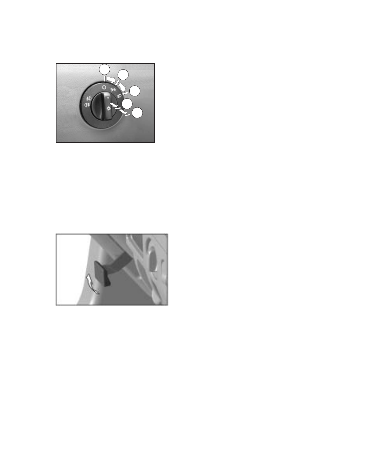
16
III — additionally (from position I or II) front fog lamps1) are ON.
IV — additionally (from position III) rear fog light is ON.
1) Mounted on some of the vehicles
Fig. 5.11. Positions of master light switch
handle.
0
I
II
III
IV
23 — ABS diagnostics button.
24 — accelerator pedal.
25 — brakes rear circuit pressure gauge.
26 — steering column adjustment control lever (fig. 5.12). Pulling the
lever and moving it upwards (within the limits of 90°) results in releasing of
the steering column. After that the steering wheel can be set in the handy po
sition for a driver and locked in this position by setting the lever to the initial
position.
Fig. 5.12. Steering column adjustment
control lever.
27 — service brake pedal.
28 — storage battery remote button switch.
29 — clutch pedal.
30 — brakes front circuit pressure gauge.
31 — fuse blocks.
32 — hood release lever. To open the hood pull lock handle to release the
catch of the lock and open the hood slightly, then push the handle back home.
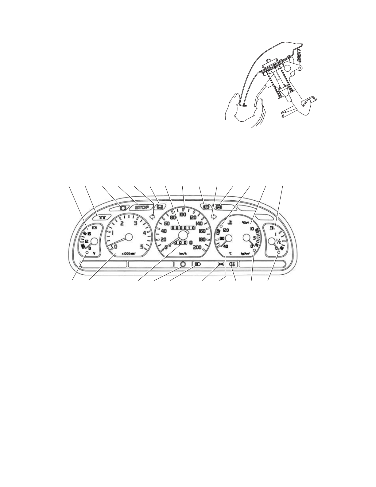
17
To open the hood completely, move aside the latch mounted on the lower
front edge of the hood (fig. 5.13).
Arrangement of instruments is shown in Fig. 5.14.
Fig. 5.13. Releasing of hood latch.
Fig. 5.14. Instrument cluster.
1234567891011121314
15161718202122
192324
1. Voltmeter.
2. Warning lamp (orange) of glow plugs cuttingin.
3. Warning lamp of brake linings wear.
4. Warning lamp (red) "STOP".
5. Warning lamp (green) of left turn indicators.
6. Reserve warning lamp.
7. Total distance counter.
8. Speedometer.
9. Warning lamp (red) of parking brake engagement.
Starts flashing after turning on the engine control switch, when the park
ing brake is engaged.

18
10. Warning lamp (green) of right turn indicators.
11. Warning lamp (red) of antilock brake system (ABS) malfunction.
12. Warning lamp (red) of engine overheating.
If the lamp lights up shut down the engine and eliminate the reason of over
heating.
13. Oil pressure gauge.
14. Fuel gauge.
15. Warning lamp (orange) of low fuel level in the tank. It lights up,
when less than 10 liters of fuel remain in the tank.
16. Warning lamp (red) of oil pressure drop. Lights up when the engine
control switch is turned on. Should the lamp light up under normal conditions,
shut down the engine immediately and check oil level in the crankcase.
17. Warning lamp (orange) of rear fog light turning on.
18. Coolant temperature gauge.
19. Warning lamp (green) of clearance light turning on.
20. Warning lamp (blue). Lights up when upper beam is on.
21. Trip distance counter reset button.
22. Trip distance counter.
23. Tachometer.
24. Warning lamp (red) of storage battery discharge.

19
6. Doors, Seats and Seat Belts
Doors. To open the door from outside, pull handle 2 (Fig. 6.1). The doors
are equipped with locks that can be locked from outside with key inserted in
lock release 3.
From inside the doors are locked by pushing down button 1.
To open the door from inside pull handle 4 with lock button 1 pulled up only.
Fig. 6.1. Cab Doors
1 — button; 2 — handle; 3 — lock release; 4 — handle
Never drive the vehicle with opened or partially closed doors.
Seats. For seating convenience the
driver seat is adjustable. By turning
handle 2 (Fig. 6.2) the seat can be
moved in lengthwise direction. Re
quired seat backrest tilt is adjusted by
rotation handwheel 3.
For driver's convenience seat tilt is
also adjusted by means of nuts 1.
GAZ331043 vehicle is equipped
with the second row of seats — two
doubleseat passenger seats.
Fig. 6.2. Driver Seat
1 — adjusting nut; 2 — locking handle; 3 —
backrest tilt handwheel.

20
To gain access to the rear passenger seats, the front passenger seat to be
moved in the direction of the driver seat. This seat shifting mechanism is simi
lar to that of the driver's seat. Before driving the vehicle shift the passenger
seat to the extreme right position by all means, otherwise safety belt will be
ineffective.
Seat belts are effective equipment to protect the driver and any passen
gers from severe injury in road accidents.
Vehicles are equipped with two types of seat belts. Inertia reel type with
three anchorage points for driver and passengers of single and outer seats as
well as lap type with two anchorage points for passengers of centre seats. Ad
justment of the inertia reel type belts is not required. As for the lap type belts,
personal adjustment of its length is necessary because intimate mating of web
bing to hips must be ensured. Changing of webbing length is performed by
means of regulator.
To fasten the belt (Fig.6.3) it is necessary to pull the belt webbing slow
ly by the tongue over the shoulder and across the chest and push it into the
buckle nearest the wearer; a click will indicate that the belt is locked.
Upper portion of the belt should pass across the centre of the shoulder so
that it is not resting on your neck or under the arm and must have intimate
mating with the upper part of your body.
Fig. 6.3. Fastening by Seat Belt
Lap portion of the belt should be positioned as low on the hips as possible.
Otherwise release the belt and adjust its length.
To release the belt, press the red panel on the buckle. The belt will auto
matically retract to its stowed position.
Pregnant women should also wear the seat belt. But she should position
the lap portion of the belt low so that it does not come across the abdomen.

21
Warning!
The belts which underwent critical loading in a road accident or they became
frayed, cut and had other damages must be renewed by new ones in assembly.
Never make any changes in the seat belt design.
Never attempt to use the seat belt for more than one person.
Keep hard or fragile objects such as glasses, fountain pens away from the
belt as they may inflict additional injuries.
The belt should not be squeezed or twisted. Keep sharp edges of the objects in
vehicle passenger compartment away from the belt.
If dirty, clean the belt with mild soap and lukewarm water only. Never iron
the belt webbings.

22
7. New Vehicle Runningin
The runningin duration is specified as 1000 km. During this period the
vehicle requires special care and special servicing as well as the following rec
ommendations should be strictly adhered to:
1. After starting until loading the engine, let it run for 2–3 minutes first at
minimum idle speed with the gradual increase up to 1500 rpm.
2. To avoid premature wear of units and parts the vehicle speed should not
exceed 60 km/h.
3. Do not overload the engine. The vehicle load must not exceed 3000 kg.
Driving the vehicle with trailer is prohibited. Besides, driving the vehicle over
tough roads, deep mud and so on should be avoided during this period.
4. Watch the condition of all fastening joints of the vehicle. Loose nuts
should be timely tightened up. Particular emphasis should be placed upon se
curing of pitman arm, propeller shaft wedges, steering knuckle arms, tie and
drag link joints, spring Ubolts, wheels and silencer intake pipes flanges.
5. During runningin period tandem transportation of the vehicles (or their
chassis) by their partial loading of one on the other is permitted when deliver
ing to customer in selfpropelled way over the road of improved type.
In such way of transportation the storage batteries of the trailing vehicle
should be removed and carried on the master vehicle. Then it is necessary to
disconnect propeller shaft flange from axle drive gear and undo screws "А" of
energy storage batteries (see Fig. 8.1).
During runningin period carry out all vehicle maintenance works speci
fied in section "Runningin" of the service book.

23
8. Vehicle Operation
8.1. ENGINE STARTING
8.1.1. Starting of cold engine
Prior to engine starting check coolant level in engine cooling system and
oil level in engine crankcase. When starting from cold, glow plugs bolting in
stalled in cylinder heads turn on automatically.
Engine cold starting is carried out in the following sequence:
1. Turn on the storage batteries switch.
2. After the longterm (for several days) parking before starting the en
gine it is recommended to prime the fuel by hand fuel priming pump.
3. Move the gearshift lever into the neutral position.
4. Depress the clutch pedal all the way down.
5. Turn engine starter key to position I (instrument cluster and engine con
trol system — ON). In doing so red warning lamp in the oil pressure gauge and
warning lamp of turning on glow plugs bolting will illuminate.
6. When warning lamp goes out switch on the starter (for not more than
15 seconds) turning the key to nonfixed position II (instrument cluster and
starter are switched on).
7. Once the engine starts release the key, which will automatically return
to position I. Red warning lamp in the oil pressure gauge goes out.
8. Release the clutch pedal.
Should the engine fail to start it is necessary to make another attempt re
peating the above procedures. Allow not less than 1 minute before the second
attempt. After the third unsuccessful attempt, find and eliminate the trouble.
Do not run the engine at idle speed for more than 15 min.
Load the engine (start driving the vehicle) when the coolant temperature
in the cooling system reaches 40° C.
Start the engine from cold with 15W/40 oil at the ambient air tempera
ture not lower than minus 15° C. When filling the engine with lowviscous
thickened oils of type М4/8П, 5W/40, 5W/50 cold starting temperature may
be lowered up to minus 25° C.
Starting of the warm engine should be carried out in the same sequence,
as the starting of the cold engine, in so doing it is not necessary to disengage
the clutch.

24
8.1.2. Starting of cold engine at low temperatures
At ambient air temperatures below –25° C (when the engine filled with
lowviscous oil) and below –15° C (when the engine filled with winter grade
oils) the following methods of engine warmingup are recommended prior to
engine starting:
a) engine heating with hot water. With the drain cock of the cylinder block
opened, hot water of 70–80° C is being poured in the radiator until water tem
perature reaches 30–40° C in the engine cooling system and warm water flows
from the drain cock. It is recommended to pour the water into the system swiftly
and continuously. To avoid water freezing in the engine radiator, hood the grill
with the radiator cover.
b) filling the engine with hot oil. In this case drain oil from the engine into
clean dishware. The oil should be heated up to 70–80° C and poured into the
engine right before starting.
Never start and run the engine with the empty cooling system. At long
term parking to avoid radiator and engine freezing, drain water from the cool
ing system and watch that all water was drained and it did not freeze in the
radiator and cylinder block drain cocks. For this purpose prick the cocks. To
expedite water drain from the system, open the radiator filler cap. When wa
ter is drained leave the cocks open.
8.1.3. Engine Stopping
Prior to engine stopping let it run for 3–5 min. at medium speed and then
at idle speed so as to reduce the temperature of coolant, oil and turbocharger.
To stop the engine release the accelerator pedal, turn off the instruments
with the key and battery switch.
8.2.VEHICLE DRIVING
It is recommended to start vehicle driving with the engine warmed up. If
there is no such possibility and the engine is warming up on the moving vehi
cle it is advisable at low temperature of ambient air and after prolonged park
ing to drive some time at low gears and low engine speed. As oil warms up it is
necessary to shift to higher gears in succession.
After wading, driving through heavy rain or after washing the vehicle brak
ing surfaces become coated with moisture. This will affect braking efficiency
until disks, drums and brake linings are dried by intermittent light application
of the brakes.

25
When moving over the pools it is necessary to lower the speed to avoid
hydroplaning, which may cause skidding and loss of control; the danger in
creases with the tires worn.
Drive the vehicle where possible without sharp acceleration and decelera
tion for this will lead to the increasing tires wear and higher fuel consumption.
To provide long and troublefree operation of the gearbox, observe the fol
lowing requirements, which will guarantee easy and noiseless gear shifting:
1. When shifting the gears, move the lever smoothly having first completely
disengaged the clutch. Too quick gear shifting will result in premature wear of
synchromesh gears or their breakdown. To increase useful life of the synchro
mesh gears it is recommended to shift from the higher to the lower gear using a
double clutch method with the intermediate increase in the engine speed with
the gearshift lever in the neutral position. Never try to change gears if the clutch
is not disengaged completely. Do not operate the pedal and the lever simulta
neously.
2. Do not engage the clutch if the gear is not changed completely.
8.3. BRAKING AND PARKING
Pneumatic disk brakes ensure steady braking efficiency. Nevertheless brake
the vehicle smoothly avoiding abrupt braking.
Do not turn off the instruments and do not remove the engine control
switch key whilst the vehicle is in motion. With the engine stopped the com
pressed air pressure drops in the brake system receivers as well as the ABS is
deactivated.
Moreover with the key removed the steering shaft will become locked by
the antitheft device and this will result in the loss of vehicle control.
In case one of the brake system circuits goes out of order the second cir
cuit provides the vehicle braking. When the parking brake is engaged, its re
leasing is possible by mechanical means only.
To provide towing of the broken vehicle it is necessary to remove screws
"A" of emergency brake release (see Fig. 8.1).
Fig. 8.1. Vehicle emergency brake release

26
When stopping the vehicle on upgrade or slope, it is necessary to engage
the parking brake and shift, respectively, into the first or reverse gear.
To avoid freezing of the brake pads to the disks after a long driving over a
wet road at sharp temperature variations, it is necessary to dry the pad linings
by smooth braking when moving to the parking place.
8.4. HEATING AND VENTILATION OF THE CAB
Heating
Fig. 8.2. Heating and ventilation control panel:
1 — handle of air distribution control in the cab:
— air flow is directed to the windscreen and door windows;
— air flow is directed to the chest of the driver and passenger;
— air flow is directed to the windscreen and door windows, to the
chest and feet of the driver and passenger;
— air flow is directed only to the feet of the driver and passenger.
2 — control handle of air amount supplied to the cab. It has four positions:
— off;
— slow speed of the blower;
— normal speed of the blower;
— fast speed of the blower.

27
3 — handle of air temperature control in the cab (passenger compartment).
The handle extreme left position (wide part of the blue symbol) activates the
ventilation mode. The intermediate and extreme right positions (wide part of
the red symbol) activate the heating mode.
Defrosting and Demisting
To remove quickly frost and condensate from the windscreen and door win
dows do the following:
— turn handle 1 (Fig. 8.2) of air distribution control to position of direct
ing air to the windscreen and door windows;
— turn handle 3 of air temperature control to the extreme right position
(wide part of the red symbol);
— turn handle 2 of air amount control to the fast speed of the blower.
To achieve a favourable climate in the cab (passenger compartment):
— turn handle 1 of air distribution control to the chosen position;
— set the air temperature you prefer (temperature of outside air or hot air
from the heater) by turning handle 3 of air temperature control;
— turn handle 2 of air amount control from position to one of the three
positions to get the desirable rate of air flow coming to the passenger compart
ment.
Central and side ventilation grids on the instrument panel have handles
(levers) for shutters control. Shifting of them changes the direction of air flow,
increases or decreases the amount of air coming to the passenger compartment
or completely closes the channel of air supply.
Ventilation
Fig. 8.3. Distribution of Air Flows in the Vehicle Cab
Cold or warm air
To cut in the ventilation:
— turn handle 3 (fig. 8.2) to the extreme left position (wide part of the
blue symbol);

28
— choose the mode of air distribution by turning handle 1;
— turn handle 2 to get the desirable rate of the air flow coming to the pas
senger compartment;
— adjust the direction of air flows by turning the shutters of ventilation
grids.
To make heating and ventilation effective be sure that the grid of the hole
for air intake located on the hood before the windscreen is free from leaves,
snow, etc.
8.5. LIGHTING AND LIGHT SIGNALING DEVICES
Caution! Headlampblock with marking ОАО "ОСВАР" lenses are made of
plastic material. That is why never use fuels and other aggressive fluids, as well
as dry brushes and wiping waste for cleaning from dust and dirt.
Remove the dirt from these parts with water jet only.
Headlamps. To replace dipped beam and clearance lamp bulbs it is neces
sary to remove rubber cover 3 (Fig 8.4).
To replace main beam bulb remove rubber covers 3 and 5, and unscrew
connector 1 to replace turn indicator bulb.
Knob 2 is designed to adjust the direction of light beam in horizontal plane.
Vertical adjustment of the light beam is carried out through opening 4 using
hexagon spanner or crosshead screwdriver.
Fig. 8.4. Headlampblock
1 — connector; 2 — light beam horizontal adjust
ment knob; 3 and 5 — rubber covers; 4 — opening
for light beam vertical adjustment
Additional vertical adjustment of the dipped beam depending on vehicle
loading is performed from the cabin by means of the headlamp aiming device
control unit handwheel.
On an unladen vehicle it is necessary to make "0" on the handwheel coin
cident with "•" mark on the control unit housing.
On a fully laden vehicle it is necessary to make "4" on the handwheel coin
cident with "•" mark on the control unit housing.

29
Adjust the headlamps in the following sequence:
— check air pressure in tires. Bring it, if necessary, to the required level;
— place the unladen vehicle on a level ground at 5 m distance from the
screen (Fig.8.5);
— bring "0" on the handwheel into coincidence with the mark on the hous
ing of the headlamp aiming device control unit;
— turn on the dipper beam;
— adjust the light beams by knobs 2 (Fig. 8.4) and through opening 4 for
each headlamp in turn.
Caution! When fitting a halogen bulb in the headlamp, do not touch the
bulb glass with the fingers to avoid luminous flux reduction or bulb rapid de
struction during its operation.
Fig. 8.5. Screen Layout for Headlamps Adjustment:
A — headlamps with "AL" marking on the lenses; B — headlamps with "ОСВАР" marking on
the lenses; h — height of vehicle headlamp dipper beam center; Y–Y — vehicle axis;
The horizontal section of light and shade border of adjusted headlamps must
coincide with line X–X (Fig. 8.5A, 8.5B), the inclined section of the light and
shade border must correspond to Fig. 8.5A (with "AL" marking on the lenses)
and Fig. 8.5B (with "ОСВАР" marking on the lenses), and the points of hori
zontal and inclined sections of the light and shade border intersection must
coincide with G–G and D–D lines.
Turn indicators and hazard light. The vehicle is equipped with electronic
flasher unit of turn indicators and hazard light, which also monitors pilot lamps
serviceability.
If, when switching on the turn indicator, pilot lamp flashes two times fast
er it means that one of the turn indicator bulbs from the vehicle right or left
side is faulty (loose connection or blowing out).
If turn indicator pilot lamp does not illuminate but turn indicator bulbs
are in good repair, the pilot lamp should be checked for serviceability.

30
If, when switching on the turn indicators, its bulbs and pilot lamp do not
light it means that fuse or turn indicator flasher unit (or its circuit) are faulty.
Tail lamps. The vehicle is provided with the tail lamps including: braking
lights, clearance lights, turn indicator lights, backing lights and fog lights.
The provision is made to install a separate fog lamp on buses and vans.
The set of horns 22.3721/221.3721 is installed under the hood on the up
per panel of the radiator cowl.
Carry out fine adjustment of the horn sound, if required. For this purpose
loosen the lock nut of the screw located on the rear side of the horn. Adjust the
sound by turning the screw to the one or the other side. Tighten the lock nut.
8.6. FUSES
Under the hood on the right there is a fuse box БПР4. 90A fuse protects
glow plugs control circuit and alternator circuit.
40 A fuse protects lighting circuit of the vehicle. 60 A fuse protects engine
shutdown solenoid control circuit.
60 A fuse (utmost) protect general positive circuit of the vehicle.
On the left two fuse boxes БПР13 are installed under the instrument
panel.
БПР13 Fuse Boxes
Upper fuse box fuses protect the circuits of:
1. 25A — ABS control unit.
2. 15A — hazard light.
3. 14A — frame switch, radio and cassette player.
4. 10A — windscreen wiper, windscreen washer.
5. 10A — headlamps relay.
6. 10A — braking lights.
7. 20A — horn, horn relay, cigarette lighter.
8. 20A — main heater, heater electric pump.
9. 15A — auxiliary heater.
10. 10A — instrument cluster, boozer, backing light, speed sensor, windshield
wiper relay.
11. 5A — ABS control unit.
12. 15A — dryer relay, starter locking relay, glow plugs control unit, fan elec
tric coupling, engine shutdown solenoid.
13.10A — turn indicators, headlamps relay.

31
Lower fuse box fuses protect the circuits of:
1. 25A — spare.
2. 15A — right headlamp main beam.
3. 15A — left headlamp main beam.
4. 10A — right headlamp dipper beam.
5. 10A — left headlamp dipper beam.
6. 10A — fog lamps, fog lamps pilot lamp.
7. 20A — spare.
8. 20A — spare.
9. 15A — under hood lamp, driver dome lamp, dome lamp of the second row
seats.
10. 10A — illumination (instruments, switches, cigarette lighter).
11. 5A — spare.
12. 15A — right clearance light, headlamp aiming device, licence plate lamp,
glove box lamp.
13. 10A — left clearance light, clearance pilot lamp, marker light on the cab
roof.
Note: Vehicles are provided with the set of spare fuses. A fuse puller is
available in the set of the spare fuses to assist removal of the faulty fuse. The
electric circuits protected by the fuses are also shown on schematic electrical
diagram.
8.7. GENERATOR SET
The vehicle is equipped with AC alternator with builtin rectifier and in
tegral voltage regulator. Maximum current output of alternator is 65A.
During operation check the generator set functioning using voltage indi
cator installed in the instrument cluster.
Basic operation rules
1. Never interconnect the voltage regulator and the alternator leads, and
connect them to the ground even for a short time because it will cause the volt
age regulator failure.
2. Never run the engine with the storage battery disconnected.
3. Never start the engine with the alternator + lead disconnected for it will
cause the generation of high voltage on the alternator rectifier dangerous for
the rectifier diodes.
4. It is prohibited to check the alternator and regulator circuit for good
condition by continuity test using megohmmeter or indicator lamp powered

32
from network exceeding 36 V. Carry out wire insulation check using megohm
meter or lamp powered from network exceeding 36 V when alternator and reg
ulator semiconductor devices are disconnected only.
5. Do not allow the direct water splashing on the alternator and regulator
during vehicle washing.
6. When servicing the alternator brush assembly it is necessary to:
— wipe brush holder and the brushes with clean cloth soaked in gasoline;
— check brushes consistency, absence of their jamming in the brush hold
ers and reliability of their contact with collector;
— brushes worn up to 8 mm are subject to replacement.
8.8 STARTER
The starter is a DC serieswound electric motor with the drive consisting
of a drive gear and a backlash roller clutch. The starter is engaged with the use
of the engine control switch key.
Maintenance service of the starter reduces to periodical checking of start
er and wires fastening and cleanout of dirt.
Starter operation instructions:
1. It is forbidden to set the vehicle in motion by the starter. It may result
in failure of the starter. In case of emergency it is allowed to move the vehicle
for not more than 5 m.
2. In winter do not persist in starting the cold engine by cranking it with
the starter for a long time without preliminary heating of the engine. This may
lead to failure of the starter and storage battery.
8.9. ANTILOCK BRAKE SYSTEM
The vehicles are equipped with antilock brake system (ABS) made by
"KNORRBREMSE". ABS is effective in case of emergency braking on the
roads with diverse road surface (example: asphaltice) and it prevents locking
of the wheels being in the least favorable road adherence condition (on the
ice) ensuring minimum braking distance of the vehicle for this road surface
(ice) while maintaining its stability and response.
Attention!
To get the best effect during emergency braking of the vehicle using ABS
it is necessary to press the brake pedal with maximum effort pushing the clutch
pedal simultaneously.
The electrical part of the ABS consists of 4 speed sensors (located in the
vehicle's wheel assemblies), 3 input choppers (on vehicle frame), control unit

33
(CU) of ABS (in cabin at the right under the instrument panel), ABS diag
nostic button (in the middle of the instrument panel), ABS failure warning
lamp (on the right in the instrument cluster) and ABS harness connecting sen
sors and input choppers with ABS CU.
Two supply circuits are connected to ABS CU: for input choppers via 1st
25A fuse in the upper fuse block and direct for ABS CU via 11th 5A fuse in the
upper fuse block.
The instrument cluster is provided with the warning lamp. It lights up for
several seconds each time the engine control switch is turned on and then goes
out. It evidences that ABS system circuits connected to ABS CU are in sound
condition. If the warning lamp lights continuously or it lights up during vehi
cle movement it indicates that ABS circuits went out of order (but service brake
system maintains serviceability as if without ABS). ABS failure warning lamp
is also lights up automatically at constrained disconnection of supply socket
from ABS control unit.
When ABS failure is confirmed the troubleshooting should be carried out
at service station.
ABS electrical diagram is shown in Fig. 8.6.
Pin
Circuit
ABS CU supply
Input chopper supply
ABS CU common
Input choppers common
Pilot lamp
Pin
D7 - control unit
887 - front, left speed sensor
Y56 - front, left input chopper
888 - front, right speed sensor
Y57 - rear, left input chopper
889 - rear, left speed sensor
890 - rear right speed sensor
Y58 - rear, right input chopper
X1 - 18 pin connector
X2 - 6 pin connector
X3 - 9 pin connector
X4 - 15 pin connector
Fig. 8.6. ABS System Electric Circuit Diagram
See vehicle electrical equipment diagram
1)
Pin
Pin

34
8.10 TOWING DEVICE
Front and rear towing devices consist of towing fork with pivot bolt locked
at below with cotter pin.
Before towing the vehicle remove the front licence plate to make access to
the towing fork. For towing the vehicle in heavy road conditions with small
turning radiuses and so on, it is recommended to remove the bumper to pre
vent its damage. In so doing it is necessary to undo 4 screws of bumper middle
part fastening and one nut (17 mm width across flat) at each side of bumper
sidewalls fastening.
9. Vehicle Maintenance
This section describes the works, which should be carried out regularly
within the intervals between the maintenance operations stated in the Service
Book.
9.1. CHECKING ENGINE OIL LEVEL
Check engine oil daily prior to engine starting. When doing so park the
vehicle on level ground. The oil level must be between "П" and "0" marks on
the oil dipstick (nearer to "П" mark). Bring it to the proper level if required.
Pour fresh engine oil via the filler neck covered with the cap.
9.2. CHECKING OIL LEVEL IN GEARBOX AND REAR AXLE
Check oil level on an unladen vehicle standing on level ground with the
units cold.
Oil level in the gearbox (Fig. 9.1) should be to the level of the filler hole
lower edge.
Fig. 9.1. Checking Oil Level in Gearbox:
1 — drain hole plug
2 — filler hole plug

35
Oil level in the rear axle (Fig. 9.2) should be to the level of the filler hole
lower edge.
9.3. CHECKING COOLANT LEVEL
Checking the coolant level in expansion tank 2 (Fig. 9.3) should be car
ried out only when the engine is cold.
Fig. 9.2. Checking Oil Level in
Rear Axle
1 — drain hole plug;
2 — filler hole plug
Fig. 9.3. Checking Coolant Level in Expansion
Tank:
1 — plug; 2 — tank
The coolant level should be at MIN mark or 30–50 mm above it.
Add antifreeze mixture through the expansion tank hole covered by cap.
If the coolant level falls frequently, inspect the cooling system for leakage.
9.4.CHECKING BRAKE LINING WEAR RATE
On the sliding calipers 1 of all disk brake gears, marking is made (see Fig.
9.4).
According to the position of "P" mark on the sliding caliper 1 against flange
"R" of caliper body 2 it is possible to determine the brake lining thickness with
out wheel removing.

36
In Fig. 9.4 "A" "P" mark position is shown when the brake pads are new.
When mark position corresponds to the position shown in Fig. "B", friction
linings and brake disk thickness should be checked with the wheels removed.
Moreover, brake pad wear indicator is installed in every disk brake to deter
mine friction linings wear. After reaching of any brake pad limiting wear the
indicator lights up on the instrument panel.
9.5. CHECKING BRAKE FLUID LEVEL IN CLUTCH MASTER
CYLINDER TANK
The level of the brake fluid in the clutch master cylinder tank should be
15–20 mm below upper edge of the tank (Fig. 9.5).
Fig. 9.4. Checking Brake Lining Wear Rate
Fig. 9.5. Checking Fluid Level in
Clutch Master Cylinder Tank
1 — service cylinder; 2 — tank; 3 — cap;
4 — reservoir

37
9.6. CHECKING STORAGE BATTERY ELECTROLYTE LEVEL
Storage battery electrolyte level should be between MIN and MAX marks
(Fig. 9.6) on the semitranslucent battery housing and in case of their absence
— to the lower edge of the filler hole.
Fig. 9.6. Storage Battery
1 — cover; 2 — plug; 3 — filler hole
If the electrolyte level is below the standard it is necessary to remove cov
er 1, unscrew plugs 2 and add distilled water through holes 3 up to the re
quired level; then screw in plugs 2 having preliminary checked the vent holes
in them for cleanness and place back cover 1. After that wipe the battery outer
surfaces with clean rugs soaked in 10% solution of ammonia spirit or sodium
bicarbonate.
Always keep the battery terminals and cable clamps clean as well as make
sure that they are securely tightened.
Care should be taken to ensure correct polarity when the battery is recon
nected after removal from the vehicle (positive terminal is bigger than nega
tive).
Prior to installation on the vehicle charge the battery bringing the density
up to 1.25–1.27 g/cm3. Depending on climatic zone of the vehicle operation
the electrolyte density should be corrected (see storage battery operating in
structions).
During the prolong parking of the vehicle disconnect the storage battery
from the vehicle frame to ensure fire safety precautions.
Battery switch. To disconnect the storage battery during the prolong park
ing or the repairing of electric equipment the battery switch is installed under
the hood on the battery plate. It operates by short pressing on the button 28
(See Fig. 5.1), placed on the fuse block bracket.

38
The battery can be switched off or on also by immediate pressing on the
switch button, covered with rubber cap.
To avoid the damage of electric equipment it is not allowed to switch off
the storage battery with the engine running.
9.7. CHECKING OIL LEVEL IN POWER STEERING RESERVOIR
Power steering system reservoir is installed under the hood on the bracket
fastened on the left headlamp case stiffener.
The level of oil should be between MAX and MIN marks available on the
reservoir body.
Fig. 9.7. Checking Oil Level in Power
Steering Reservoir
9.8. ENGINE ACCESSORIES DRIVE BELT TENSION
Fan belt tension (Fig. 9.8) should be checked by pressing with 4,0 daN
(4,0 kgf) force on the side middle between pulleys of crankshaft and alternator
in doing so the belt sag amount must be within 12–17 mm. To adjust the belt
tension it is necessary to loosen alternator fasteners, turn it and tension the
belt. Tighten alternator fasteners.
Fig. 9.8. Checking Fan Belt Tension

39
9.9. WHEELS AND TIRES CARE
In the process of vehicle operation it is necessary to timely tighten the loose
wheel nuts to avoid damaging the fastening holes, remove rust from the wheels
and restore their colour.
To ensure maximum service life of the tires the following rules should be
observed:
— maintain the required air inflation pressure in the tires. Pressure should
be checked when the tires are cold before starting out. When stopping during
a trip carry out visual inspection of the tires and inflation pressure in them.
Never drive the vehicle with the underinflated tires even for a short distance.
Pressure should not be reduced in warm tires because during the vehicle move
ment pressure increase is inevitable due to heating of air inside them;
— check and balance the wheels with tires on a special stand at the service
station. The allowable residual unbalance from each side of the wheel with tire
should not exceed 100 g on the wheel rim;
— on returning from a trip and when at halt inspect the tires and remove
the foreign objects. The vehicle should be parked on clean and dry place. Avoid
oil, gasoline, oil paint getting on the tires;
— prevent vehicle standing with underinflated tires;
— rotate the tires (Fig. 9.9), if necessary to get even wear of all tires, spare
one including, as well as to provide proper selection of the tires for each axle.
The tires on an axle should be of the same tread wear and more reliable tires
should be installed on the front axle of the vehicle.
Fig. 9.9. Tire Rotation
Diagram
Maximum permissible rate of tread wear corresponds to residual depth of
the tread grooves equal to 1.6 mm which is determined by measurement or by
tread wear indicators. These indicators of 1.6 mm high will appear as wide bands
incorporated in the tread pattern and marked on the tire sidewalls by TWI
marks.

40
9.10. CHANGING A WHEEL
Replace the wheel in the following sequence:
— apply the handbrake;
— place chocks under the wheels from the side opposite to the wheel to be
removed;
— loosen six nuts of the wheel to be removed;
— place the jack (Fig. 9.10) under front axle beam or rear axle near the
wheel to be lifted and drive out screw 2 by hand as far as it will go. In case of
loose ground, place a pad or a firm board under the jack base;
Fig. 9.10. Jack
1 — head; 2 — screw; 3 and 4 — operating plungers; 5 —
handle; 6 — delivery plunger; 7 — shutoff needle; 8 — plug
— screw shutoff needle 7 all the way clockwise, insert tommy bar into han
dle 5 and rocking the tommy bar make lifting of the vehicle so that the wheel
clears the ground by 4–5 mm;
In case of failure of lifting by the jack, open shutoff needle 7 and rock the
tommy bar several times to remove air which could get into the working cham
ber.
Plunger liftoff limitation is mechanical, by effort increasing on the handle
at the end of the lifting stop the lifting.
— remove six nuts of the wheel, replace the wheel and fit the nuts;
— lower the vehicle slowly opening shutoff needle 7 of the jack by turn
ing it in a counterclockwise direction;
— tighten six nuts and remove the chocks;
— adjust the tire pressure.
When using and storing the jack the following rules should be observed:
1. To maintain vehicle stability place chocks under the wheels of the op
posite side and apply the handbrake.

41
2. Do not work beneath the vehicle with the lifting jack as the only sup
port.
To carry out adjustment and mounting/dismounting operations lift the
vehicle on the jack and then lower it on suitable stands.
3. In storage jack screw 2 should be driven all the way in, the operating
and delivery plungers must take the lowermost position and shutoff needle 7
be unscrewed through 1 or 2 revolutions.
4. Fill the jack with clear filtered oil ВМГЗС or МГЕ10А up to the level
of the filler hole.
At the ambient air temperature up to – 40° C application of transformer
oil is permissible.
Never use oils of other grades and liquids including brake fluid.
Jack failures should be eliminated timely. Seepage of oil in the plungers
and shutoff needle is eliminated by tightening the packing gland nuts. Oil leak
age through the joints of the body is corrected by tightening the body head.
Worn packing glands should be replaced.
Jack failure results from air presence in the working chamber or due to
valve sticking. To eliminate failure tap lightly on the delivery plunger handle
several times and continue the lifting. To prevent air from getting into the
working chamber of the jack, do not lift the operating plunger by hand with
the shutoff needle closed.
Incomplete lifting of the jack operating plunger occurs due to shortage of
oil. Regularly check the oil level in the jack and replenish, if required. The oil
level in the vertically positioned jack should reach the filler throat closed with
plug 8.
Failure in operation except for mentioned reasons may result from dirt,
which got inside the jack. To clean the jack interior of dirt, unscrew the jack
body head, pour clean kerosene into the body and pump the jack several times
with the shutoff needle open. Drain kerosene and pour fresh oil.
9.11. CAB CARE
Wash the vehicle in a shadow. Do not use soda, kerosene, gasoline as well
as seawater. If after washing with water the cab is not clean enough you may
use shampoo and other vehicle cosmetics available in the market.
Use clean sponge and soft cloth with plenty of water and do not rub too
hard.
Tar spots should be removed with castor or petrolatum oil. A mild soap
solution or pure water may easily clean the plastic parts. Never use gasoline or
solvents for the above purpose.

42
On detecting corrosive spots it is necessary to remove the rust to pure metal,
prime and apply corrosionresisting mastic.
At frosty weather you should not wash the vehicle outofdoor or drive
with wet or just washed cab, because by water freezing cracks may appear on
painted surface.
You should not keep the vehicle under rubberised cover or place rubber
articles on bodywork painted surface because dark spots may appear which
cannot be removed with car polish.
To retain elasticity of rubber seals at low temperatures, it is recommended
to smear them with glycerine at regular intervals.
In the process of vehicle operation noncorrosive coating of the cab may
fail with time that is why it is necessary to perform corrosionresisting treat
ment at regular intervals at service stations.
Hidden pockets additional corrosion protective treatment areas diagram
of the cab is shown in Fig. 9.11.
Fig. 9.11. Hidden Pockets Additional
Corrosion Protective Treatment Areas
Diagram of the Cab
1 — foot steps hidden pockets; 2 — door pock
ets; 3 — front fender with mudguard contact
area; 4 — hood pocket around the periphery;
5 — door hinges area
9.12. TYPES OF MAINTENANCE
The following types of maintenance are established:
1. Daily maintenance (EO).
2. Maintenance one "A" (TO1) — after 10000 km of run.
3. Maintenance two "B" (TO2) — after 20000 km of run.
4. Seasonal maintenance "C" (CO).
Seasonal maintenance is performed once a year along with maintenance
one "A" or two "B".

43
9.13. PROCEDURES CARRIED OUT DURING MAINTENANCE
9.13.1. Daily Maintenance (EO)
Procedure description Specifications
Tools and
materials
12
Check the level of:
— oil in engine crankcase See item 9.1 Visually
— fluid in cooling system See item 9.3 Visually
— fluid in clutch master See item 9.5 Visually
cylinder tank
— oil in power steering See item 9.7 Visually
reservoir
1)
Check service brake sys 1. With the engine running, the Visually
tem for sound condition. brake pedal should not reach the
cab floor.
2. With the engine running, the
buzzer should not work except
for the time necessary for recei
ver feeding after the engine start
ing.
Check operation of parking Parking brake handle should
brake system easy move and securely tune in
parking position.
Check tire inflation pres Check when tires are cold. Air Manometer
sure, bring to the specifi inflation pressure values see in
ed, if required subsection 4.10 "Main adjust
ment and checking data"
Check steering wheel total Total play over steering wheel
play rim should not exceed 25°
(10° — for the vehicles during
the warranty period) in each side
from the neutral position
Check operation of instru With the engine running make Visually
ments, windshield wiper, sure that the devices are in sound
illumination and warning condition by their successive
devices turning on
3
1) In case of oil low level in the reservoir, check power steering system for tightness

44
9.13.2. Periodic Maintenance (TO1, TO2, CO)
Procedures for periodic maintenance are stated in the service book sup
plied with the vehicle.
9.13.3. Vehicle Lubrication
1.Never use fuels, oils and liquids of other grades except for those specified
in subsections 9.13.4 and 9.14.
2.Prior to lubrication remove dirt from grease nipples and plugs to avoid
its penetration into the vehicle's mechanisms.
3.Lubricate with grease gun until fresh lubricant comes out from all joints
and seals.
4.When the engine oil is changed for another grade or company the lubri
cating system should be flushed with flushing oil.
Never mix (top up) engine oil of different grades and different companies.
9.13.4. Lubrication Chart
Description of lubrication
points
Number
of points
Quantity
of lubri
cant
Description of lubricant
1 23 4
Engine oil system 1 12 l In summer — engine oils: М10Г2 or
М10Г2K ААИД1 or engine oil
М10ДМ ААИД2.
In winter — engine oils: М8Г
2
or М
8Г2 ААИД1 or, engine oil: М8ДМ
ААИД2.
Allseason: engine oil SAE 15W40
Api CF4; CF4/SG (up to –15° C);
SAE 5W40 Api CF4; CF4/SG (up
to –25° C);
Gearbox case 1 6 l At the temperature from –25° C to
+40° C — oil "Супер Т3". Substi
tutes — oils ТСп15К, "Девон Супер
Т", "Лукойл ТМ5" SAE 85W90.
At the temperature from –40° C to
+20° C — oil "Лукойл ТМ5" SAE
75W90
Universal joint needle 3 4 g Oil "Супер Т3". Substitute — oil
bearings "Девон Супер Т", "Лукойл ТМ5"
SAE 85W90

45
1 23 4
Propeller shaft slip joint 1 200 g Oil "Супер Т3". Substitute — oil
"Девон Супер Т", "Лукойл ТМ5"
SAE 85W90
Intermediate propeller 1 50 g Grease Литол24. Substitute —
shaft bearing grease ЛИТА
Steering knuckle pivot 4 30 g Solid oil Ж or solid oil C
bearings
Rear axle housing and At the temperature from –25° C to
rear wheels hub bearings 1 8 l +40° C — oil "Супер Т3". Substi
tute — oil "Девон Супер Т", "Лукойл
ТМ5" SAE 85W90
At the temperature from 40° C to
+20° C — oil "Лукойл ТМ5" SAE
75W90
Front wheels hub bear 4 400±30 g Grease Литол24. Substitute —
ings grease ЛИТА
Rear wheel hub seal 2 20 g Grease Литол24
Shock absorbers 4 550 cm
3
АЖ12T. Substitute fluid — spindle
oil AУ
Power steering system 1 1.3 l Hydraulic oil "P"
Steering shaft sealing 1 5 g Grease Литол24. Substitute —
grease ЛИТА
Steering gear universal 3 6 g Grease Литол24. Substitutes —
joints solid oil C, solid oil Ж
Master clutch cylinder 1 0.2 l Brake fluid "РОСДОТ".
refilling tank (system Substitute fluid "Томь"
capacity) class III grade A
Storage battery terminals 4 4 g Lubricant ПВК or solid oil
Door locks and linkages 14 20 g Oil ВМГЗ or МГЕ10А
(inner and outer)
Door lock releases 2 4 g Grease Литол24. Substitute —
grease ЛИТА
Cab door limiters 2 2 g Grease Литол24. Substitute —
grease ЛИТА
Hood lock 1 1 g Oil ВМГЗ or МГЕ10А
Hood lock control 1 15 g Grease Литол24. Substitute —
grease ЛИТА
Hood hinges 2 2 g Oil ВМГЗ or МГЕ10А
Engine cooling system 1 16 l Coolant ТОСОЛА40М, ОЖ40
"Лена", ТЕРМОСОЛА40

46
9.14. EQUIVALENTS OF RUSSIAN AND FOREIGN FUELS, OILS,
LUBRICANTS AND FLUIDS
Russian fuel, oil, lubricant,
fluids
Foreign fuel, oil, lubricant,
fluids
Recommended t° ranges, °C
(ambient)
123
Diesel oil
Л0,5 2D (ASTM97581) Above 0° C
З0,535 1D (ASTM97581) From 0° C to –20° C
Engine oils
М10Г
2
к or ABOVE +5° C
М10Г
2
М10ДМ
М8 Г
2
к or Below –5° C
М8 Г
2
М8 ДМ
APISF 4 ACE 2E2:
SAE 15W40 From +45° C to –15° C
SAE 10W40 From +35° C to –20° C
SAE 5W40 From +35° C to –25° C
Transmission oils
"SUPER T3 (TM5)" or API GL5, SAE 85W90, From –25° C up to +50° C
"UFALUB UNITRANS" MILL2105B
or "DEVON SUPER T
(TM18)"
Lubricants
Litol24 MilG18709A, from –40° C to +60° C
MilG10924C
Fat or synthetic solid oil MilG10924C from –40° C to +50° C
Lubricant (ПВК) MilC11796B From –40° C to +50° C
ЛИТА SM1C4515A (Ford) For cold climatic zone
No.158 NICO GREASE 57
"Nico International Inc."
or Alvania Grease 2 (MoS
2
)"
"Shell International
Petroleum Co. Ltd"
Graphite grease УСcА VVG671d 078.01 (RFA)

47
123
Power steering oil
Oil grade "A" ATF For tropic climatic zone
Oil grade "P" ISO6074HM22 From –35° C to +45° C
Spindle oil АУ ISO6074HH22 From –25° C to +45° C
Oil ВМГЗ ISO6074HV15 For cold climatic zone
Shock absorber fluid
АЖ12т VTL9150033 Above –45° C
Oil МГЕ10A ISO6079HV15 For cold climatic zone
Brake fluids
"РОСДОТ" DOT4 SAE J1703 For all climatic zones
"Toмь" FMVSS 116
DOT3 SAE J1703 For moderate climatic zone
FMVSS 116
Coolants:
ТОСОЛА40М Antifreezing agent with From –40° C to +50° C
ОЖ40 "Лена" corrosion inhibitor complex
ТОСОЛА65М and foamquencher For cold climatic zone
ОЖ65 "Лена"
While choosing the lubricant or fluid give preference to the following com
panies: Shell, Mobil, Castrol, British Petroleum, Agip, Gulf.
9.15. PARTS TO BE REPLACED ON THE VEHICLE DURING
MAINTENANCE
During vehicle maintenance the following parts are subject to replacement:
1. Fine fuel filter element.
Filter element designation is 2401117030.
Fine fuel filter care includes draining sediment at regular intervals and re
placement of filter element.
To drain sediment from fine fuel filter it is necessary to unscrew plug 4
(Fig. 9.12) and drain sediment until clean fuel appears then tighten the plug.
To renew filter element it is necessary to:
— drain fuel from the filter removing plug 4;
— unscrew cover retaining nuts and remove cover 1;
— withdraw filter element 2 from the body;
— clean the inside of the filter body;
— reassemble the filter with new filter element;

48
— unscrew plug 3 (Fig. 9.13) on fuel pump housing to bleed air and un
screw union 1 by 1–2 turns on the fine fuel filter;
— prime the system by means of booster pump 2, when fuel appears screw
in union 1 first and then tighten plug 3.
Fig. 9.12. Fine Fuel Filter Element
Replacement:
1 — filter cover; 2 — filter element; 3 — fil
ter body; 4 — plug
Fig. 9.13. Air Bleeding from Fuel System
1 — union; 2 — booster pump; 3 — plug
2. Air filter element.
Filter element designation is 4301110901310 or 4301.110901320.

49
3. Oil filter, solid, replaceable.
Filter designation is ФМ0091012005.
When installing the filter, lubricate the rubber gasket with engine oil and
screw the filter onto the engine cylinder block.
As soon as the gasket touches the cylinder block, add more 3/4th of the
turn. Installation of the filter is carried out by hands effort only.
Instead of filter ФМ0091012005 it is allowed to use the filterssubsti
tutes X149, firm "ACDelco" (France) and L37198, company "Purolator" (Ita
ly) with basic dimensions:
— diameter — 95–120 mm
— height — 140–153 mm
— mounting thread 3/4" — 16UNF.
4. Filter element of power steering system reservoir ШНКФ 453473.
In case of installation of power steering system reservoir ЯМЗ.993.004 the
latter is replaced in assembly.
5. Filter element of dryer 1117793, firm "KnorrBremse".

50
10. Supplements
Supplement 1
10.1. FILLING CAPACITIES
Fuel tank, 105
Engine cooling system, l 21,5
Engine oil system, l 12
Gearbox case, l 6
Rear axle housing, l 8
Power steering system, l 1,3
Shock absorbers (each), cm
3
137,5
Clutch hydraulic drive system, l 0,2
Lubricant for front wheel hubs (both), g 400±30
Lubricant for rear wheel hubs (both), g 40
Windscreen washer tank, l 4
Supplement 2
10.2. ELECTRIC BULBS USED
Purpose and location Type Quantity
Head lamps:
low beam H7 2
high beam H1 2
clearance light W5W 2
turn indicator PY21W 2
Turn indicator repeater PY21W 2
Front marker lights A125 2
Side clearance lamps W3W 4
Tail lights:
turn indicator A12213 2
stoplight A12213 2
clearance light A1210 2
backing light A12213 2
fog light A12213 2
Side clearance marker light A1210 2
Instrument cluster
pilot lamps A121,21 24
instrument illumination bulbs A122,31 4
Pressure gauge (manometer) AMH1231 2
Cab dome lamp A1251 3
A1231 1
Glove box dome lamp A1251 1
Hood light A1210 1
Licence plate light A125 4

51
Purpose and location Type Quantity
Cab dome lamp for vehicles with twobank cab KЛУ9/ТБЦ1 1
Control unit of head lamp aiming device A121,21 1
Instrument illumination control ACMH120,55 1
Heating and ventilation unit control desk A121,2 4
Cigar lighter socket lighting A121,2 1
Alarm switch pilot lamp A121,1 1
Main light switch A121,2 2
Supplement 3
10.3. ROLLING BEARINGS USED IN THE VEHICLE
LocationType of bearing Bearing No.
Engine
Single seal ball bearing 1160305 2 Water pump
Taper roller bearing 7204A 2 Fuel pump
Thrust ball bearing 8110 1 Fuel pump governor
Thrust ball bearing 8202 1
Singlerow radial ball bearing 205K 2 Power steering pump drive
Singlerow radial ball bearing 6203 or 6203AK 2 Vacuum pump
Singlerow radial ball bearing 207 2 Compressor
Transmission
Radial ball bearing 1280114C23 1 Clutch release sleeve
Singlerow radial ball bearing 6311AKУ 1 Gearbox output shaft, rear
Singlerow radial ball bearing 60205К 1 Gearbox input shaft, front
Singlerow radial ball bearing В6213АКУШ 1 Gearbox input shaft, rear
Radial roller bearing without 64706 1 Gearbox reverse pinion shaft
races
Ball Б 11,112200 306203П 3 Transmission shifter shaft
lock
Ball 10100 296870 4 Transmission shifter shaft
lock plunger
Singlerow taper roller bearing 7207A 2 Intermediate shaft
Radial roller bearing without 264706 1 Gearbox output shaft, front
races
Doublerow needle radial rol 664910E 5 Gearbox output shaft
ler bearing without races pinions
Needle roller bearing with one 804805K1 12 Propeller shaft pivot joints
outer race
Singlerow radial ball bearing 6114 1 Propeller shaft bearing
Singlerow taper roller bearing 27709У4Ш2 1 Rear axle drive pinion, cen
ter
Singlerow taper roller bearing 27308AKУ 1 Rear axle drive pinion, front
Singlerow taper roller bearing У807813А 2 Rear axle differential
Singlerow radial roller bearing 20102605М 1 Rear axle drive pinion, rear
Quantity

52
LocationType of bearing Bearing No. Quantity
Steering gear
Radial ball bearing 6930904FT1C17 2 Steering column
Needle roller bearing with one 904700УС17 10 Steering gear shaft pivot
outer race joints
Running gear
Singlerow taper roller bearing 4807813A 2 Outer support of rear wheel
hub
Singlerow taper roller bearing 67515A 2 Inner support of rear wheel
hub
Singlerow taper roller bearing 7610A 2 Front wheel hub, inner
Singlerow taper roller bearing 7607AУ 2 Front wheel hub, outer
Electrical equipment
Singlerow radial ball bearing 6180502K1C9 1 Alternator
6180603KC9 1
Supplement 4
10.4. SEALS USED IN THE VEHICLE
Engine
Engine crankshaft seal, rear 2401002305 1
Engine crankshaft seal, front 2401002055 1
Water pump seal 2401307038Б 1
Transmission
Gearbox output shaft flange seal 511701210A 1
Rear axle drive pinion seal 512402052Б4 1
Input shaft bearing cap seal (42x62x10) 309827П 1
Steering gear
Seal 20x32x7 33023401022 1
Running gear
Seal of front hub in assembly with spring 43013103038 2
Seal of rear hub in assembly with spring 513104038132 2
Quantity per
vehicle
No. of sealDesignation

53
Tension bolts of:
Cylinder head 19–21
Main bearing caps 20–22
Flywheel 18–20
Crankshaft balance weights 12–14
Crankshaft pulley 24–28
Injection nozzles 2–2.5
Cardan drive flanges 12–16
Transfer drive reduction gear and drive pinion bearings clutch 9–11
Starter 5–6.2
Retaining nuts of:
Connectingrod bearing bolts 18–20
Clutch case to cylinder block 4.4–6.2
Gearbox to clutch 7–10
Gearbox output shaft flange 28–36
Steering wheel 6.5–8
Spring Ubolts:
front 12–15
rear 20–22
Wheels 36–44
Steering gear bracket to frame 8–10
Steering gear to bracket 25–32
Axle drive pinion flange 28–40
Drop arm 30.5–33
Note: Tightening torques are given for checking during repairing and maintenance.
Tightening torque,
daN·m (kgf·m)
Junction description
Supplement 5
10.5. TIGHTENING TORQUES OF MOST IMPORTANT
JUNCTIONS

54
Contents
Page
Introduction .....................................................................................................................................2
1. Vehicle Identification Data .....................................................................................................3
2. Useful Hints .................................................................................................................................5
3. Safety Precaution Rules ........................................................................................................... 6
4.Specifications ................................................................................................................................7
5. Controls and Instruments .....................................................................................................11
6. Doors, Seats and Seat Belts ..................................................................................................19
7. New Vehicle Runningin .......................................................................................................22
8. Vehicle Operation ................................................................................................................... 23
8.1. Engine Starting ................................................................................................................ 23
8.2. Vehicle Driving ................................................................................................................ 24
8.3. Braking and Parking ....................................................................................................... 25
8.4. Heating and Ventilation of the Cab ........................................................................... 26
8.5. Lighting and Light Signaling Devices ....................................................................... 28
8.6. Fuses .................................................................................................................................... 30
8.7. Generator Set .................................................................................................................... 31
8.8. Starter ................................................................................................................................. 32
8.9. Antilock Brake System ................................................................................................. 32
8.10. Towing Device ............................................................................................................... 34
9. Vehicle Maintenance .............................................................................................................. 34
9.1. Checking Engine Oil Level ........................................................................................... 34
9.2. Checking Oil Level in Gearbox and Rear Axle ....................................................... 34
9.3. Checking Coolant Level ................................................................................................ 35
9.4. Checking Brake Lining Wear Rate ............................................................................ 35
9.5. Checking Brake Fluid Level in Clutch Master Cylinder Tank .......................... 36
9.6. Checking Storage Battery Electrolyte Level ........................................................... 37
9.7. Checking Oil Level in Power Steering Reservoir .................................................. 38
9.8. Engine Accessories Drive Belt Tensioning .............................................................. 38
9.9. Wheels and Tires Care ................................................................................................... 39
9.10. Changing a Wheel ......................................................................................................... 40
9.11. Cab Care ........................................................................................................................... 41
9.12. Types of Maintenance .................................................................................................. 42
9.13. Procedures carried out during Maintenance ......................................................... 43
9.13.1. Daily Maintenance (EO) ............................................................................... 43
9.13.2. Periodic Maintenance (TO1, TO2, CO) ................................................ 44
9.13.3. Vehicle Lubrication ......................................................................................... 44
9.13.4. Lubrication Chart ............................................................................................ 44
9.14. Equivalents of Fuels, Oils, Lubricants and Fluids ..................................... 46
9.15. Parts to be Replaced on the Vehicle during Maintenance ...................... 47

10. Supplements............................................................................................................................ 50
10.1. Filling Capacities ........................................................................................................50
10.2. Electric Bulbs Used .................................................................................................... 50
10.3. Rolling Bearings Used on the Vehicle .................................................................. 51
10.4. Seals Used in the Vehicle .......................................................................................... 52
10.5. Tightening Torques of Most Important Junctions ............................................ 53
Отпечатано в ООО «Печать НН», E5.
 Loading...