

Gaymar Thermacare REF TC3249 Service Manual
Gaymar Industries, Inc.
10 Centre Drive
Orchard Park, NY 14127-2295 USA
Telephone: +1 716 662-8636
+1 716 662-2551
Fax: +1 716 662-0730
+1 716 662-6120
www.gaymar.com
Gaymar and Thermacare trademarks are registered
in the US Patent and Trademark Office.
©2010. Gaymar Industries, Inc.
All rights reserved.
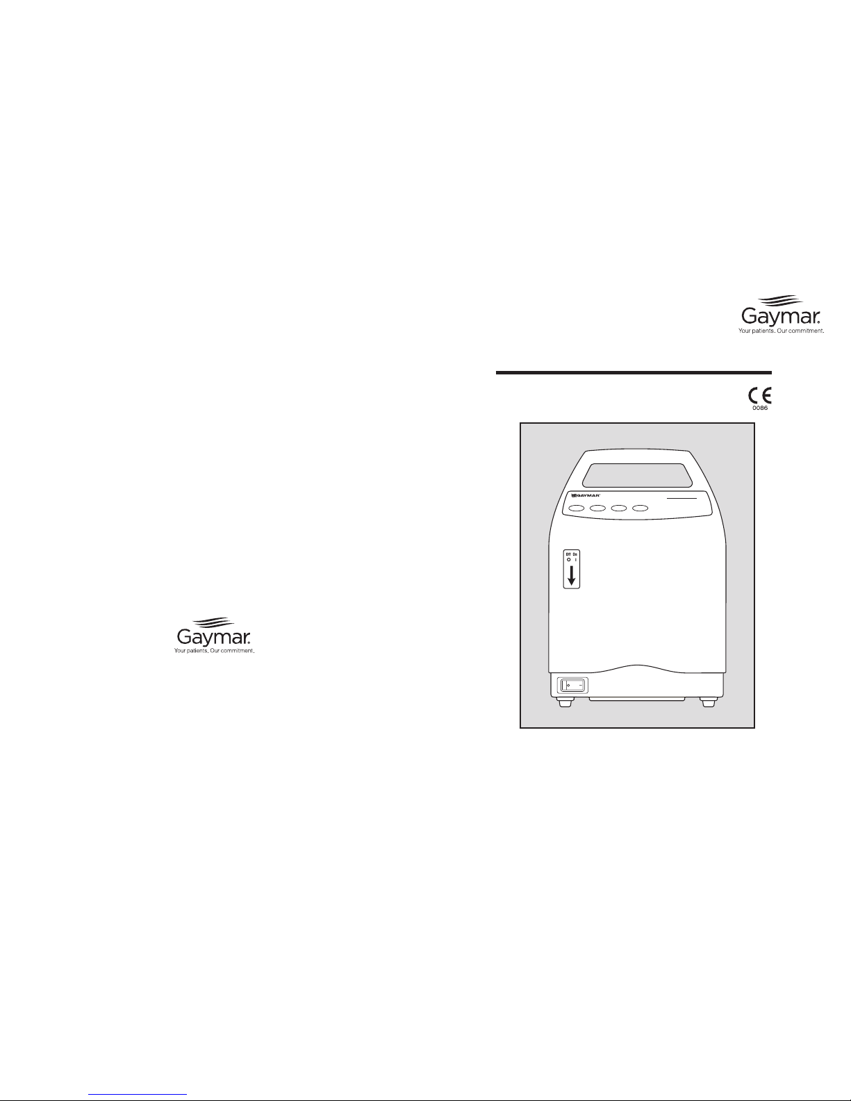
Thermacare® REF TC3249
Convective Warming System
Service Manual
P/N: 100077000 Rev. C 11/10
Thermacare
Before you begin . . .
Important
• Refer to the TC3249 Convective Warming
System Operating Manual for detailed
operating instructions. Read and understand
the Operating Manual and all precautions prior
to using the Convective Warming System.
•Review the SAFETY PRECAUTIONS (see page
2) prior to servicing the Convective Warming
Power Unit.
•Fortechnicalassistance,contactyourlocal
dealer.
NOTE: Extremely high storage temperatures
(such as those found in rail cars or automobile
trunks on hot summer days) can cause the
thermostats within this device to actuate. Should
this occur, the REMOVE FROM USE indicator
will light when the Power Unit is turned on. If
this happens, the thermostats must be manually
reset. Refer to section 7, Functional Check and
Safety Inspection.
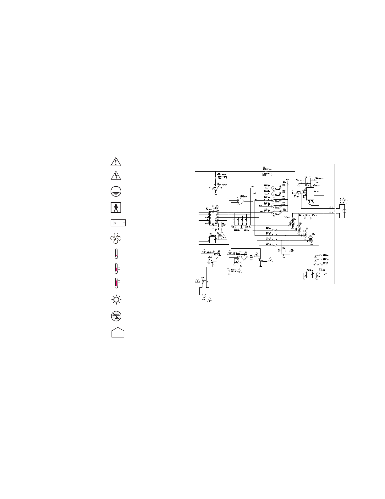
Attention: consult accompanying
documents
Dangerous voltage
Protective earth (ground)
Type BF applied equipment
MIN (Fan only)
LOW (90°F, 32°C)
MED (100°F, 38°C)
HIGH (110°F, 43°C)
Do not use in operating room
(OR) or Intensive Care Unit (ICU)
Off-on switch
REMOVE FROM USE
(indicator light, amber color)
Symbols used within this manual:
60°F - 85°F
(16°C - 29°C)
Ambient operating temperature
29
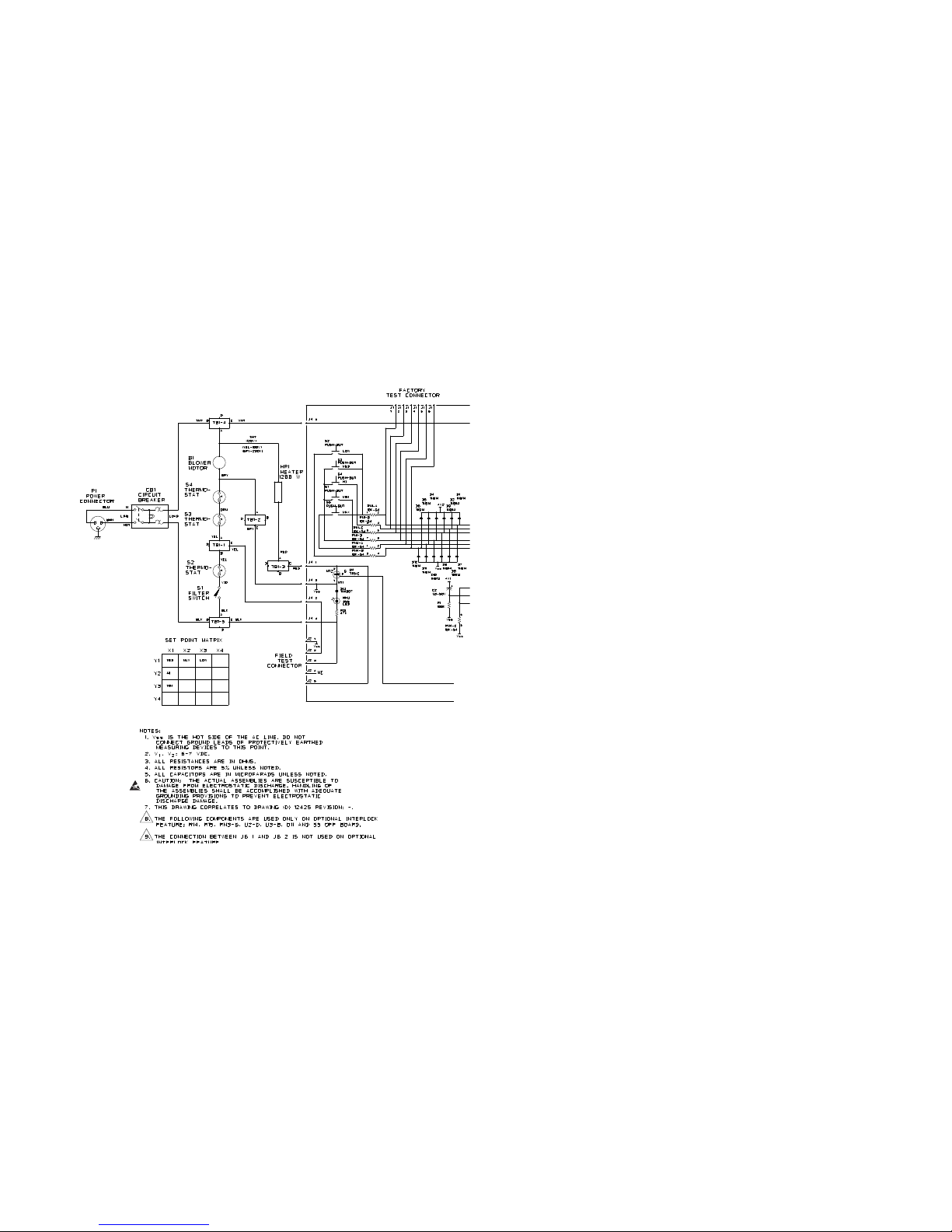
Section 13 - Wiring Diagram (cont’d)
Contents
Section Introduction Page
1.0 Safety Precautions ................................................................2
2.0 Repair Policy / Return Authorization ....................................... 3
3.0 Specifications .......................................................................4
4.0 Theory of Operation ..............................................................5
5.0 Controls and Indicators .........................................................7
6.0 Preventive Maintenance ........................................................7
7.0 Functional Check and Safety Inspection .................................8
8.0 Inspection Form ..................................................................16
9.0 Troubleshooting ..................................................................19
10.0 Repair Procedures ..............................................................21
11.0 Drawings/Parts List ............................................................24
12.0 Test Tool Schematic ............................................................27
13.0 Wiring Diagram ...................................................................28
Illustrations
Figure Description Page
1 Convective Warming System ...............................................5
2A/B Power Unit Mounting ...........................................................5
3 Pole Mounting Height Limit ..................................................5
4 Operator Control Panel .........................................................6
5 Test Tool..............................................................................9
6 Temperature Sensor Location .............................................10
7 Troubleshooting Chart - NO HEAT ......................................19
8 Troubleshooting Chart - NO AIR FLOW ................................20
9 Drawing/Parts List ..............................................................24
10 Drawing/Parts List ..............................................................25
11 Drawing/Parts List ..............................................................26
12 Test Tool Schematic ...........................................................27
13 Wiring Diagram ..................................................................28
Tables
Table Description Page
1 Air Temperatures ..................................................................4
2 Functional Check/Inspection Form .......................................16
Table of Contents
128
Section 13 - Wiring Diagram
Figure 13 - Wiring Diagram
ATTENTION
Static-Sensitive
Device s
2
1.0 Safety Precautions
Review the following SAFETY PRECAUTIONS prior
to testing the Power Unit.
•After per forming the thermostat test
procedure, verify that the Test Tool or any
installed test jumpers have been removed
before returning the Power Unit to patient
use.
Failure to remove the Test Tool or test
jumpers may result in death, serious
injury or equipment malfunction.
•AlwaysunplugthePowerUnitbefore
attaching or removing the Test Tool
or test jumpers and when resetting
thermostats. Failure to unplug the Power
Unitcouldresultinelectricalshockand
cause death or serious injury.
•Use only Gaymar replacement parts as
identified in the parts lists (pp. 24-27).
Useofsubstitutepartscouldleadto
power unit malfunction or patient injury.
•TheTemperatureControlPCBoardis
pre-set at the factory. Do not attempt to
calibrateit.AdjustmentoftheControl
PC Board in the field could result in
patient injury.
•Use care when resetting the thermostats.
Excessive force (force greater than
5 pounds) can damage the overtemp
protection device and/or inadvertently
alter the trip temperature of the device.
DANGER
•Explosivehazard.Donotuseinthe
presence of flammable anesthetics.
•Riskofelectricshock.Disconnectpower
before servicing the TC3249 Power Unit.
W ARNING
W ARNING
This device generates heated air flow.
Excessive heat could cause thermal
stressorskinlesions.Failuretofollow
these precautions could result in death or
serious injury:
•Use this system only under direction of
a physician. Read and understand the
Operating Manual, Quilt Instructions for
Use, and all precautions before using.
•Repairs should be performed only by
qualified personnel such as certified
biomedical electronics technicians or
certified clinical engineers familiar with
repair practices for servicing medical
devices, and in accordance with the
Service Manual. Damage to the Power
Unitormalfunctioncouldotherwise
result.
•AlwaysperformtheFUNCTIONAL
CHECK AND SAFETY INSPECTION after
makingrepairsandbefore returning the
PowerUnittopatientuse.Document
your findings on the INSPECTION
FORM. Improper repair may result
in death or serious injury, equipment
damage, or malfunction.
(continued next column)
Section 1 - Safety Precautions
•U.S.Federallawrestrictsthisdeviceto
sale by or on the order of a physician.
•For grounding reliability, plug only into a
grounded outlet labeled “Hospital Grade.”
•The HEPA filter must be installed correctly.
Failure to install the filter correctly will
prevent it from functioning properly and
could allow unfiltered air to reach the
patient.
•When using an I. V. pole, do not mount
the Power Unit higher than 3 feet
(0.9 meter). Otherwise, the Power Unit
could tip over.
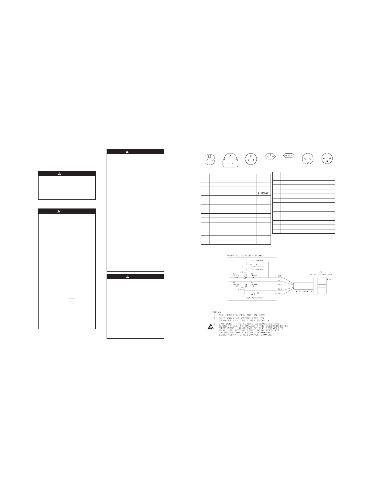
Section 12 - Test Tool Schematic
ATTENTION
Sta tic- Sensitive
Devices
27
Figure 12 - Test Tool Schematic
(see Figure 11/11A)
Section 11 - Drawings/Parts Lists (cont’d)
Item Description Part
Number
30 Label, Caution 12762000
32 Cord strap assembly 03791000
33 Heater thermostat (S4) 78025000
34 Interlock switch 91375000
35 Sleeving 4 1/2" LG 81054000
- Power cord (Continental Europe) PC001
- Power cord (United Kingdom) PC002
- Power cord (Australia) PC003
- Power cord (Switzerland) PC004
- Power cord (Italy) PC005
- Power cord (Denmark) PC006
- Power cord (Israel) PC007
PC001
PC004
PC006PC002 PC005 PC007PC003
Item Description Part
Number
16 Power entry module 08993000
17 Motor kit 78022000
18 Patient limit thermostats (S2,S3) 91323005
19 Hose assembly 78423000
20 Kit, card, label replacement 78110000
21 Rear housing kit (includes labeling) 78118002
22 I.V. pole clamp 08614000
23 Toggle shoe 91439000
24 Card, Contraindication, Greek/Blank 09877000
25 Card, Contraindication, Swedish/Finnish 09876000
26 Card, Contraindication, Dutch/Danish 09875000
27 Card, Contraindication, Italian/German 09874000
28 Card, Contraindication, Spanish/ Portuguese 09873000
29 Card, Contraindication, English/French 09872000
Figure 11A - Plugs
CAUTION
2.0 Repair Policy
For customers who repair Gaymar Power Units at
their location, this manual contains information to
allow a qualified biomedical technician to make
necessary repairs.
2.1 Limited Warranty
The Thermacare TC3249 Power Unit is warranted
free of defects in material and workmanship
under normal use and operation for a period of
two years, under the terms and conditions of the
Gaymar warranty in place at time of purchase.
During the warranty period, Gaymar will repair
or replace at its sole option, free of charge, any
defective parts or products returned with prior
authorization prepaid to Gaymar Industries.
Consumable items such as filters are excluded.
The full warranty is available from Gaymar upon
request.
Warranty does not cover products abused,
misused, or altered outside the factory. There
are no obligations on the part of Gaymar for
consequential damages arising out of or in
connection with the use or performance of the
product. Gaymar disclaims all implied warranties
including, but not limited to, the implied
warranties of merchantability and of fitness for a
particular purpose.
2.2 In-Warranty Repairs
All in-warranty field repairs must be authorized by
Gaymar's Export Depar tment before proceeding.
2.3 Out-of-Warranty Repairs
If the Power Unit becomes inoperative and the
cause cannot be determined, the complete
Power Unit may be returned to the factory for
servicing at the purchaser's expense. Please
contact Gaymar's Export Depar tment to obtain a
returned goods (“RG”) number prior to returning
equipment.
2.4 ReturnAuthorization
Please contact your local dealer.
Section 2 - Repair Policy
3
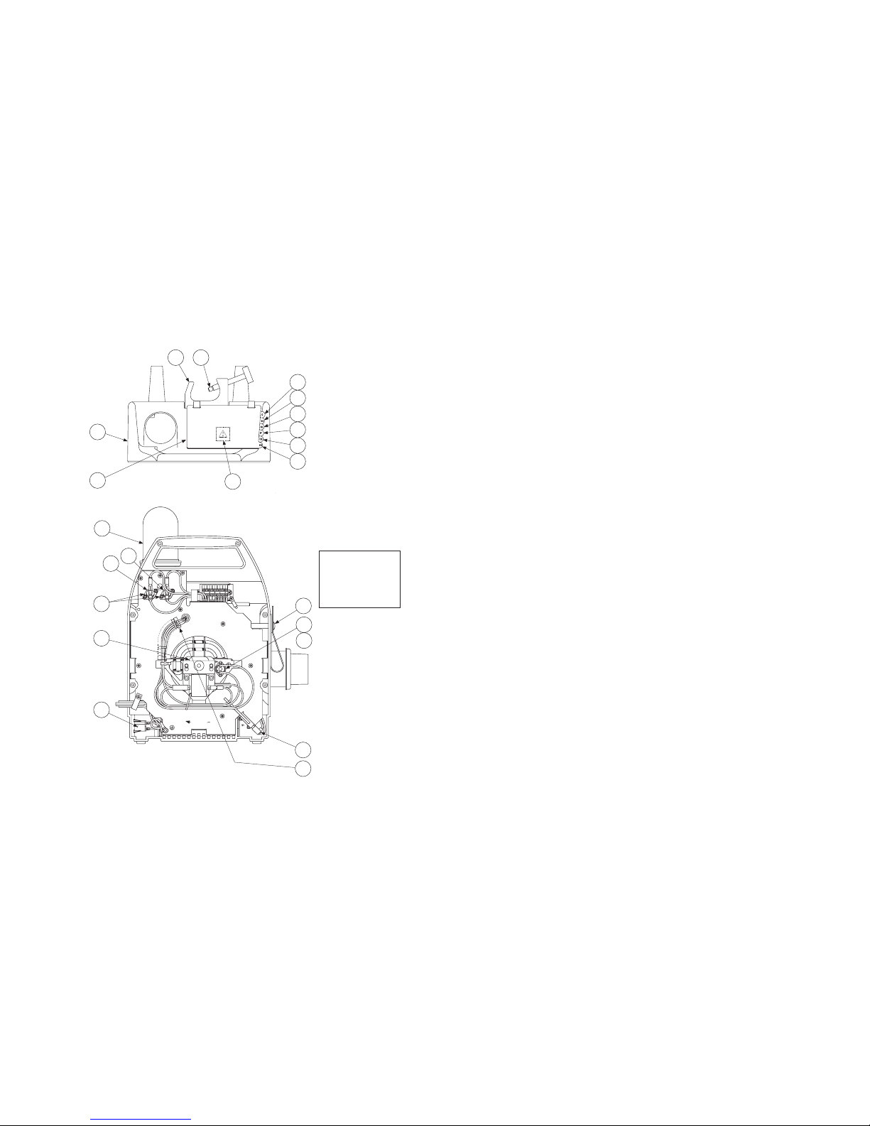
Figure 11 - TC3146 Detail Drawing
Section 11 - Drawings/Parts Lists (cont’d)
26
To release wires from
terminal block, insert
a small screwdriver in
slot nearest wire and
pull towards center.
S3
S2
S4
16
17
18
19
22
23
24
20
21
25
26
27
28
29
30
32
33
34
35
ROTATION
 Loading...