

Page 1
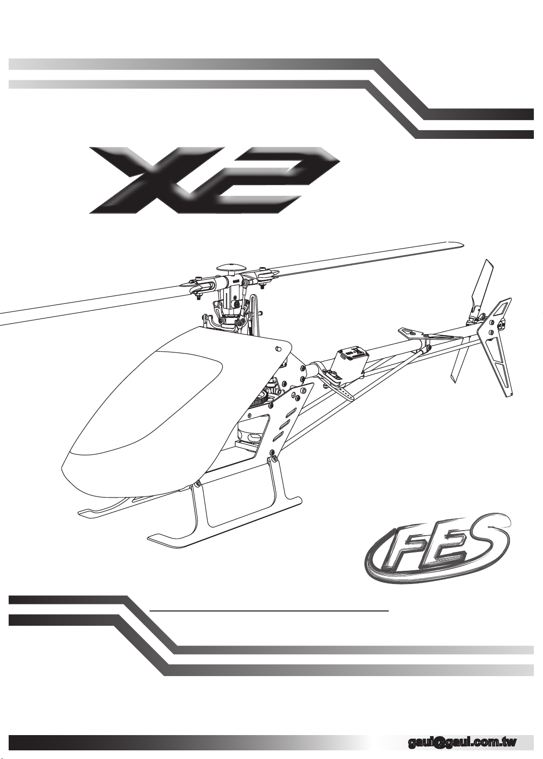
ASSEMBLY INSTRUCTION
Recommendation:
We highly recommand using the latest version of the Assembly Instruction Manual.
To download the latest version, please visit the Offi cial TSH GAUI web site: www.gaui.com.tw
取得最新的手冊:
我們非常建議您取得最新版本的手冊。
請到泰世網站下載最新的手冊,並且取代目前的手冊。
GAUI
V1.0.4
Page 2

Page 3
1
2
3
組裝代號說明,產品規格 升級維修零件表
4
Preface
前言 主旋翼總成組裝
Tools for Assembly
自備工具 尾旋翼總成組裝
Assembly Notice,
Main Frame assembly
5
6
7
機體總成組裝
Mair Rotor Assembly
Tail Rotor Assembly
Upgrade & Replacement Parts
Preface
1
前言 皮帶方向確認
Academy of Model Aeronautics (AMA) P.3
Tools for Assembly
2
自備工具清單 尾伺服機組裝
Symbols for Assembly Notices
組裝代號說明 電裝配置/機構檢查-1
3
Specication Check - 2
產品規格 機構檢查-2
Upper Front Fuselage Assembly
上前側板組裝 機構檢查-3
4
Upper Back Fuselage Assembly
上後側板組裝 升級維修零件表
Fuselage Plates Assembly
前後側板組裝
Main Axis Assembly
馬達組裝
Servos Assembly
下側板組裝
Motor Assembly - 1
上下側板組裝
Motor Assembly - 2
旋翼夾頭組裝
5
Mixing Arms Assembly
剪型臂組裝
Swash Plate Assembly
十字盤組裝
Main Rotor Assembly
主旋翼拉桿配置
Adjust Gear Mesh and Tail Fin Assembly
尾殼組裝
6
Servo Horns Assembly
雙推系統組裝
Tail Rotor Assembly
尾旋翼夾頭組裝
Tail Fin Assembly
尾翼組裝
P.1 ~ P.2
P.4
P.5
P.6
P.7
P.8
P.9
P.10
P.11
P.12
Belt Direction Check
Main Gear Assembly
主齒盤安裝
Tail servo Installation
Electronics Intallation & Check - 1
Check - 3
Upgrade & Replacement
7
P.13
P.14
P.15
P.16~ P.17
Page 4
Preface
前言
GAUI
TAI SHIH HOBBY CORPORATION
Thank you for purchasing GAUI High Performance RC Helicopter from
Tai Shih Hobby Corporation (TSH). We hope you will enjoy the joy of ight.
感謝您購買泰世科技出品的
飛行的樂趣。
GAUI
高性能遙控直升機,我們希望您可以盡情享受
In order to understand full assembly sequences, this instruction manual shows
the assembly information of this model, even though some elements are
supplied as pre-assembled. Please refer to this manual when carrying
out maintenance or replacing parts.
為了要讓使用者詳細瞭解組裝順序,即使有些部件已經預先組裝完成,
本說明書將提供這台遙控模型的組裝資訊。同時,敬請參閱保養與主要零件更換資訊。
CAUTION: This radio controlled helicopter is not a toy.
警告:這台遙控直升機不是玩具。
SAFETY PRECAUTIONS
This kit includes some preassembled components. Please check for any
loose screws and tighten them before you proceed with assembly.
You are responsible for assembly, safe operation, maintenance, inspection and
adjustment of the model.
Before beginning assembly, please read these instructions thoroughly.
Check all parts. If you nd any defective or missing parts, contact your local
dealer or GAUI TSH distributor.
Before you proceed to RC helicopter activity, please check and follow thoroughly
related regulation of aero modeling in your country/region.
安全資訊與注意事項
這台遙控模型包含預先組合完成的部件。
在進行組裝之前,請仔細檢查這些預先組裝部件上的所有螺絲均有仔細鎖緊。
您有完全的責任對於這台遙控模型的組裝,安全操作,保養,檢查與調整。
請先檢查所有的零件,如果發現任何不良品,遺失品,請向模型店或是當地的
泰世代理商連絡。
在您進行遙控直升機活動時,請先詳細瞭解與遵守當地遙控模型的相關法規。
1
Page 5
LIABILITY DISCLAIMER
免責聲明
GAUI
TAI SHIH HOBBY CORPORATION
LIABILITY DISCLAIMER
This product is for a radio controlled (RC) helicopter.
Improper operation, maintenance or assembly can potentially cause a RC
helicopter to pose a danger to persons or objects including but not limited to
the possibility of causing serious physical injury and even death.
Moving components can present a hazard to operators, and anyone or anything
that could be in the ying area of the RC helicopter.
Under no circumstance should a minor be allowed to operate this RC helicopter
without the approval, monitor and direction of his parent or legal
guardian who takes full responsibility for all of the minor's actions.
This product is intended for being operated by experienced mature radio control
helicopter pilots under controlled safety conditions and on locations
properly authorized and setup for safe ying and away from other people.
Do not operate an RC helicopter within the vicinity of residences, trees, electrical
power lines during inclement weather or near crowds of people.
The manufacturer and/or its distributors assume no responsibility or liability
whatsoever for any damages including but not limited to ones generated
by incidental or consequential damages.
The operator of the helicopter assumes all responsibility and liability that results
from the correct or incorrect operation of the helicopter.
After leaving its facilities, the manufacturer has no way of maintaining control or
monitor over the assembly, maintenance and/or operation of the
helicopter.
免責聲明
這個產品是無線遙控的直升機。
不當的操作,保養或是組裝有可能導致遙控直升機對於人身或是物品造成危險。
包括,但是不局限於對於人體產生嚴重傷害甚至死亡的可能性。
所有的移動部件可能對於操作的使用者,旁人或是這台遙控直升機飛行場的
任何人或物品產生傷害。
未成年的人如果要操作這台遙控直升機需要父母或是監護人的同意,
並在監督與指導下才能進行操作並遠離周遭障礙物及人群等,其父母或是監護人
需負起所有責任與法律責任。
以下場合與情況禁止操作遙控直升機:居家房屋附近、天候不佳時、非空曠區域、
樹木、電線竿等場合或是人群附近。
製造廠商與其經銷商都不對於所有的傷害,包含但是不局限於偶然或是連續發生的
傷害負擔任何責任。
本產品的使用者要對於正確地或是不正確地操作的結果需負擔所有責任與法律責任。
本產品一但離開製造廠商的控制範圍外,製造廠商無法對於下列事項保持監督與控管:
組裝,保養,維修與操作這台遙控直升機。
2
Page 6
Academy of Model Aeronautics (AMA)
GAUI
TAI SHIH HOBBY CORPORATION
For United States market, The Academy of Model Aeronautics (AMA) is
a national organization representing modelers in the United States.
Please refer the National Model Aircraft safety code from Academy of Model
Aeronautics. And we’ve partially reprinted rules that are especially pertinent for
radio controlled ight as below:
RADIO CONTROL
1. All pilots shall avoid ying models over unprotected people.
2. I will complete a successful radio equipment ground-range check in
accordance with the manufacturer’s recommendations before the rst ight of
a new or repaired aircraft.
3. At all ying sites a safety line or lines must be established, in front of which all
ying takes place. Only personnel associated with ying the model
aircraft are allowed at or in front of the safety line.
In the case of air shows or demonstrations a straight safety line must be
established.
An area away from the safety line must be maintained for spectators.
Intentional ying behind the safety line is prohibited. (See AMA Document #706
for Recommended Field Layout.)
4. I will operate my model aircraft using only radio-control frequencies currently
allowed by the Federal Communications Commission (FCC).
Only individuals properly licensed by the FCC are authorized to operate
equipment on Amateur Band frequencies.
5. I will not knowingly operate my model aircraft within three (3) miles of any
preexisting ying site without a frequency-management agreement.
(See AMA Document #922 for Testing for RF Interference. See AMA Document
#923 for Frequency Management Agreement.)
6. With the exception of events own under ofcial AMA Competition Regulations
rules, excluding takeoff and landing, no powered model may be
own outdoors closer than 25 feet to any individual, except for the pilot and the
pilot’s helper(s) located at the ight line.
7. Under no circumstances may a pilot or other person touch a model aircraft in
ight while it is still under power, except to divert it from striking an
individual. This does not apply to model aircraft own indoors.
8. Radio-controlled night ying requires a lighting system that provides the pilot
with a clear view of the model’s attitude and orientation at all times.
9. The operator of a radio-controlled model aircraft shall control it during the
entire ight, maintaining visual contact without enhancement other
than by corrective lenses that are prescribed for the pilot. First-Person View
(FPV) ying may only be conducted in accordance with the
procedures outlined in AMA Document #550.
These special codes and appropriate documents may be obtained either from
the AMA Web site at www.modelaircraft.org or by contacting AMA headquarter.
Academy of Model Aeronautics
5151 East Memorial Drive
Muncie, IN 47302
Phone: (800) 435-9262
Fax: (765) 741-0057
3
Page 7
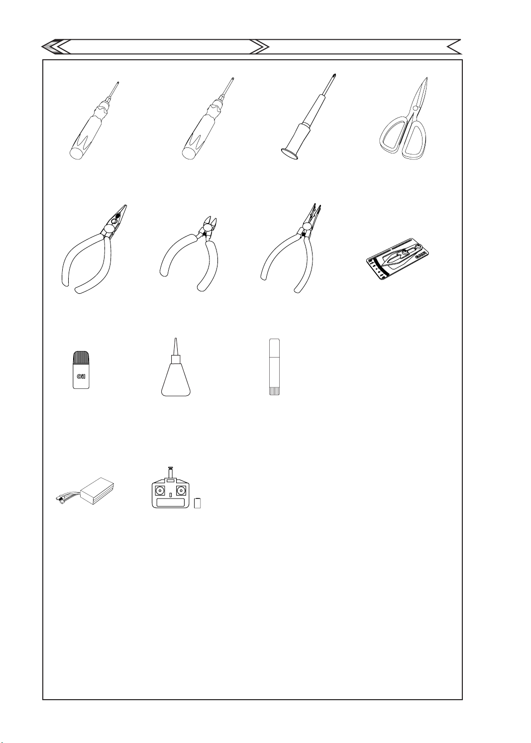
Tools for Assembly
2.0mm Hexagon Screw Driver 2.5mm Hexagon Screw Driver Philips Screw Drive Scissor
2.0mm 六角螺絲起子 2.5mm 六角螺絲起子 十字螺絲起子 剪刀
Needle-nosed pliers Diagonal cutting plier Ball Link Plier Dial Pitch Gauge
尖嘴鉗 斜口鉗 拔豆鉗 主旋翼螺距規
自備工具及設備
GAUI
TAI SHIH HOBBY CORPORATION
CA
Lubricant CA Thread Lock
潤滑油 瞬間膠 螺絲止鬆劑
Battery 3S 11.1v
鋰聚電池3S 11.1v
Transmitter (6-channel or more
helicopter system)
六動以上接收機&發射機
4
Page 8
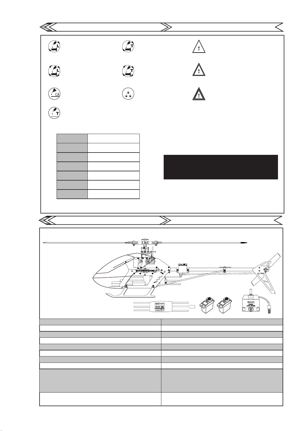
Symbols for Assembly Notices
組裝代號說明
GAUI
TAI SHIH HOBBY CORPORATION
Apply general thread lock.
To tighten screw, apply thread lock.
一般型止鬆劑
鎖緊螺絲並確認上膠
Apply general thread lock.
Be certain to tight screw and
apply thread lock.
一般型止鬆劑
務必鎖緊螺絲並確認上膠
Apply CA glue
使用瞬間黏著劑
Apply special thread lock
使用特殊型止鬆劑。
B-Bearing
B-軸承
Ø-TapScrew
粗牙螺絲
Ø-
M-Machine Screw
M-公制螺絲
P-tube
P-柱狀體
Pillar
P-柱狀體
N-Nut
N-螺母
W-Washer
華司
W-
B(Dia.in)x(Dia.out)x(Thickness)
B(內徑)X(外徑)X(厚度)
Ø(Dia.out)x(Length)
Ø(外徑)X(長度)
M(Dia.out)x(Length)
M(外徑)X(長度)
P(Dia.in)x(Dia.out)x(Length)
P(內徑)X(外徑)X(長度)
P(Dia.out)x(Length)
P(外徑)X(長度)X(實心柱)
N(Dia.in)x(Width) L-Lock nut
N(外徑)X(長度)
W(Dia.in)xDia.out)x(Thickness)
W(內徑)X(外徑)X(厚度)
Apply special thread lock.
To tight screw and apply thread lock.
特殊型止鬆劑
鎖緊螺絲並確認上膠
Apply special thread lock.
Be certain to tight screw and
apply thread lock.
特殊型止鬆劑
務必鎖緊螺絲並確認上膠
Apply lubricant
依個人需求使用潤滑油。
Ma ke su re to asse mb le the par ts as show n in fig ur e abo ve .
Incomplete or incorrect assembly may cause control failu re during
ight.
以上圖示,於組裝時請確實注意,避免組裝後試飛造成失控零件
鬆脫等情況發生。
Attention: Pay attention, care should be taken
during assembly.
注 意: 組裝過程中請注意並小心安裝。
Extreme attention:
More attention should be taken during assembly.
Double check after assembly.
非 常 注 意 : 組裝過程中請非常注意並
小心安裝及再確認組裝無誤。
Danger:
High level of attention should be taken during
assembly.
Action during assembly might be hazardous.
Extreme care should be taken to avoid injury.
危 險: 組裝過程中請小心安裝並注意
此危險程度可能造成安全性漏洞
導致人為傷害。
Specication
規格資料
Overall Length (with Canopy): 500Specications
Main Rotor Diameter: 560mm
Main rotor blades: 255mm
Overall Height: 161mm
Overall Width: 83mm
Tail Blade Length: 45mm
Tail Rotor Diameter: 111mm
Flying duration: 5~6 minutes
Power System(Recommanded):
Motor -- 3400KV
ESC 22A ESC
3S(11.1v/900mAh)
Total weight: 334g ±3% (Equipped with Blades and
all electronic gears except Battery).
GAUI
This manual is for reference only. Check your kit for actual contents
207022
TAI SHIH HOBBY CORPORATION
本欄位僅提供說明,實際內容物請參考盒裝內容。
x3
922095 922093
207202
機身長度(含艙罩): 500mm
主旋翼迴轉直徑: 560mm
主旋翼長度: 255mm
機身高度: 161mm
機身寬度: 83mm
尾旋翼葉片長度: 45mm
尾旋翼迴轉直徑: 111mm
飛行時間:5~6分鐘
動力系統(原廠建議):
馬達 3400 KV
電子變速器 22A ESC
使用鋰聚電池:3S(11.1v / 900mAh)
全配重量:334g ±3% (全套含電子裝備不含電池)
5
Page 9
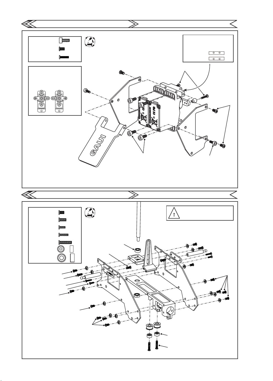
Front Fuselage Assembly
上前側板組裝
GAUI
TAI SHIH HOBBY CORPORATION
a.M2x5
b.M2x3.2
c.M1.4x6
Make adjustment to the
servo horns with the
servo in neutral position.
請在伺服器中立狀態下,
組裝伺服器舵片並修剪多餘的舵片。
PIT AIL
Apply thread lock on all
screws in this section.
螺絲均需上止滑劑
a.M2x5
b.M2x3.2
a.M2x5
Make sure to assemble the Upper /
Lower Mount at the correct position
as shown in Figure.
組裝伺服機座鋁柱時請注意方向性
Upper Mount
Lower Mount
c.M1.4x6
a.M2x5
b.M2x3.2
Upper Backside fuselage assembly
a.M2x3.2
b.M2x4.6
c.Ø1.4x4
d.Ø1.4x6
e.M2x8.4
f.B2x5x2.5
g.B3x6x2
a.M2x3.2
b.M2x4.6
d.Ø1.4x6
c.Ø1.4x4
a.M2x3.2
a.M2x3.2
a.M2x3.2
上後側板組裝
Apply thread lock on all
screws in this section.
螺絲均需上止滑劑
g.B3x6x2
b.M2x4.6
GAUI
TAI SHIH HOBBY CORPORATION
When assembling the side frames,
the main shaft can be placed in and
tightened.
組裝側板時可將主軸置入在鎖緊螺絲。
a.M2x3.2
b.M2x4.6
d.Ø1.4x6
c.Ø1.4x4
a.M2x3.2
a.M2x3.2
f.B2x5x2.5
e.M2x4.6
6
Page 10
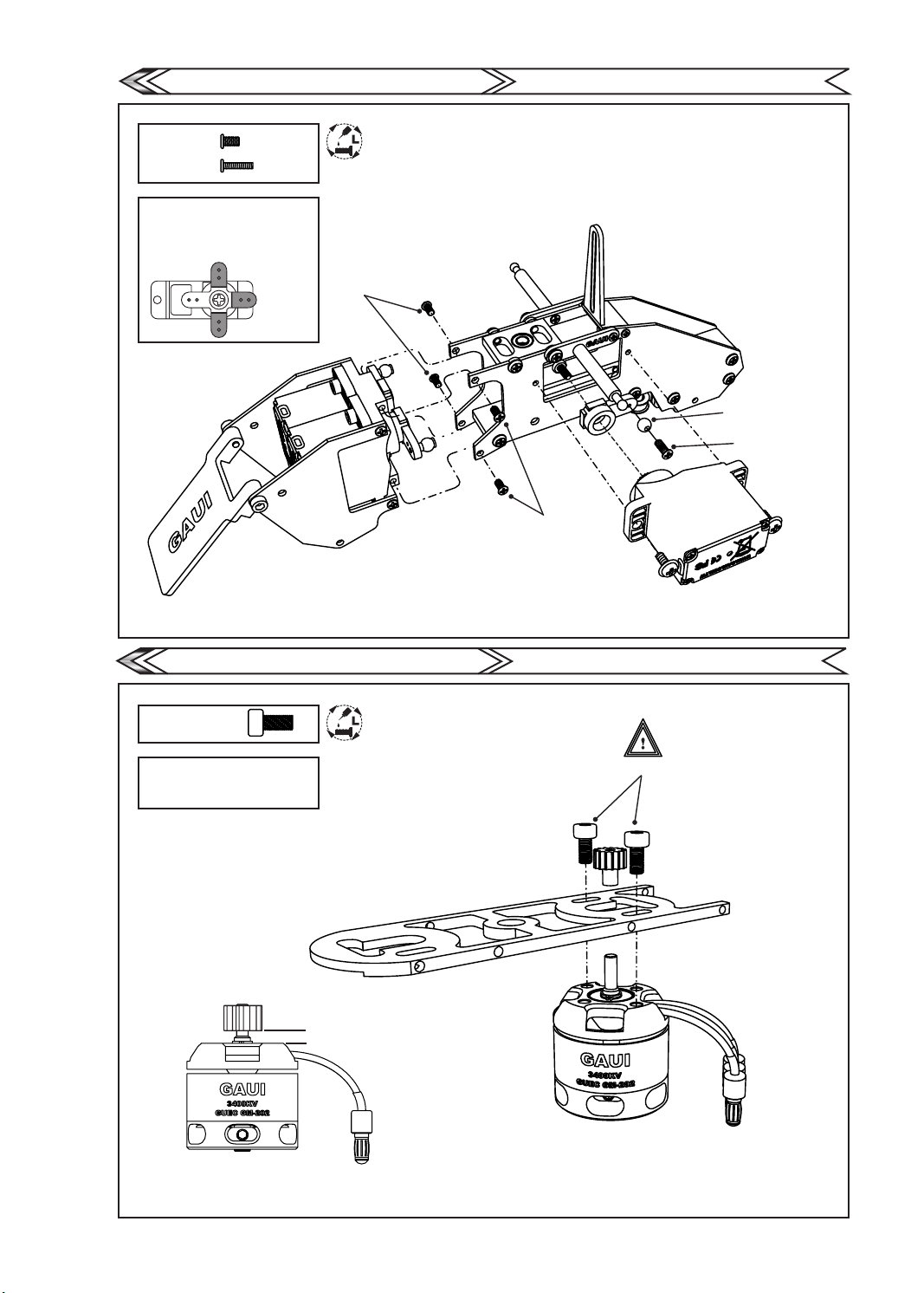
Front and Back Fuselage Assembly
a.M2x3.2
b.M1.4x6
Make adjustment to the
servo horns with the
servo in neutral position.
請在伺服器中立狀態下,
組裝伺服器舵片並修剪多餘的舵片。
前後側板組裝
Apply thread lock on all
screws in this section.
螺絲均需上止滑劑
GAUI
TAI SHIH HOBBY CORPORATION
ELE
Motor Assembly
a.M3x6
Install Motor and mount motor gear
and screws.
No need to tighten screws .
組裝馬達並鎖上M3x4,不鎖緊。
a.M2x3.2
馬達組裝
Apply thread lock on all
screws in this section.
螺絲均需上止滑劑
a.M2x3.2
GAUI
3.5mm
短球頭
Ball without Stand
b.M1.4x6
TAI SHIH HOBBY CORPORATION
a.M3x6
(1-1)
4.5mm
7
Page 11
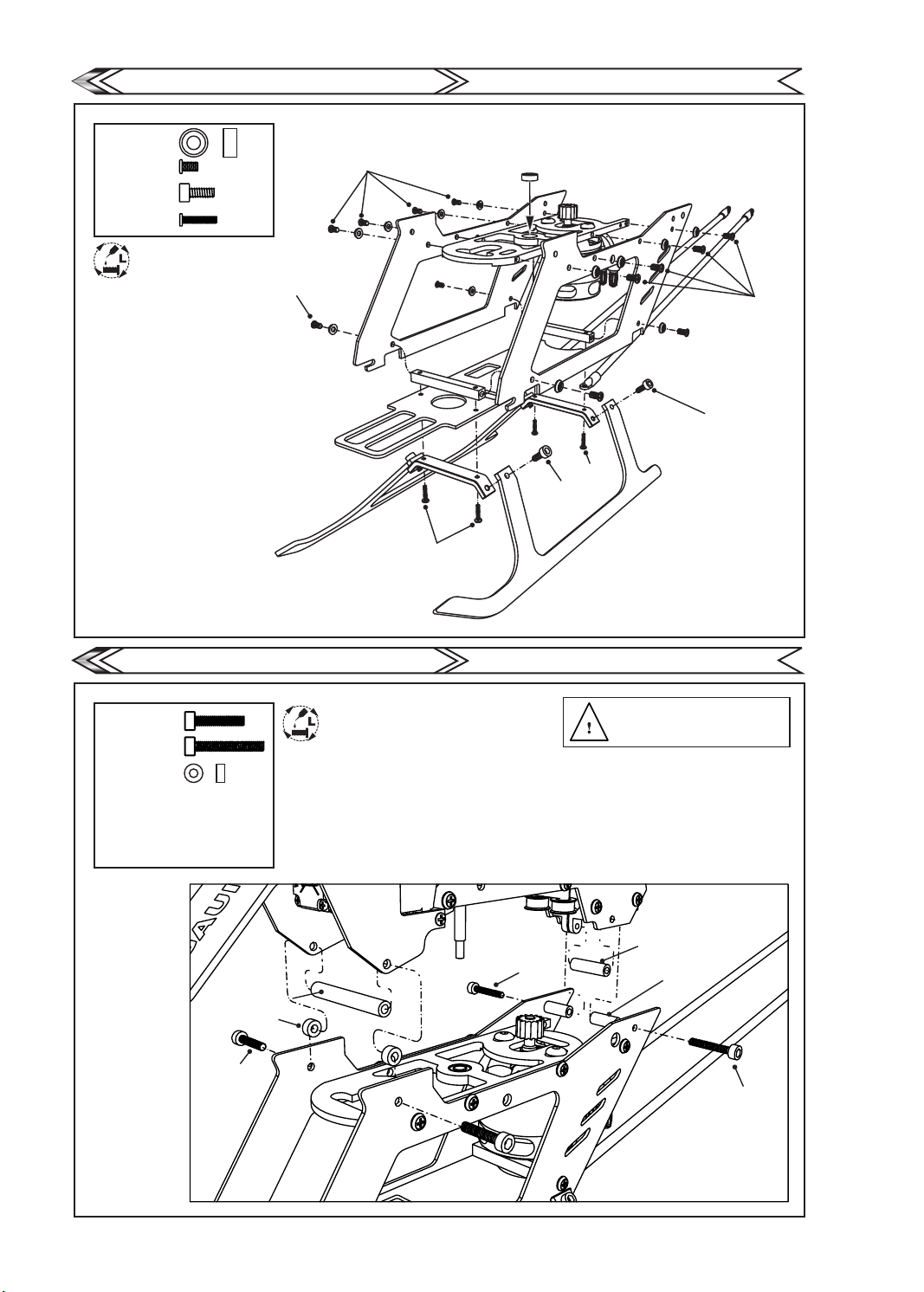
Bottom Fuselage Assembly
a.B3x6x2
b.M2x3.2
c.M2x5
d.M1.4x7
Apply thread lock on all
screws in this section.
螺絲均需上止滑劑
b.M2x3.2
下側板組裝
b.M2x3.2
d.M1.4x7
GAUI
TAI SHIH HOBBY CORPORATION
a.B3x6x2
b.M2x3.2
c.M2x5
d.M1.4x7
c.M2x5
Upper & Lower Fuselage Assembly
a.M2x10
b.M2x14
c.P2x4x2
d.P2x3.5x25
e.P2x3.5x8.5
f.P2x3.5x12
d.P2x3.5x25
c.P2x4x2
a.M2x10
上下側板組裝
Apply thread lock on all
screws in this section.
螺絲均需上止滑劑
GAUI
b.M2x14
TAI SHIH HOBBY CORPORATION
When assembling the side frames,
the main shaft can be placed in and
tightened.
組裝側板時可將主軸置入在鎖緊螺絲。
f.P2x3.5x12
e.P2x3.5x8.5
b.M2x14
8
Page 12
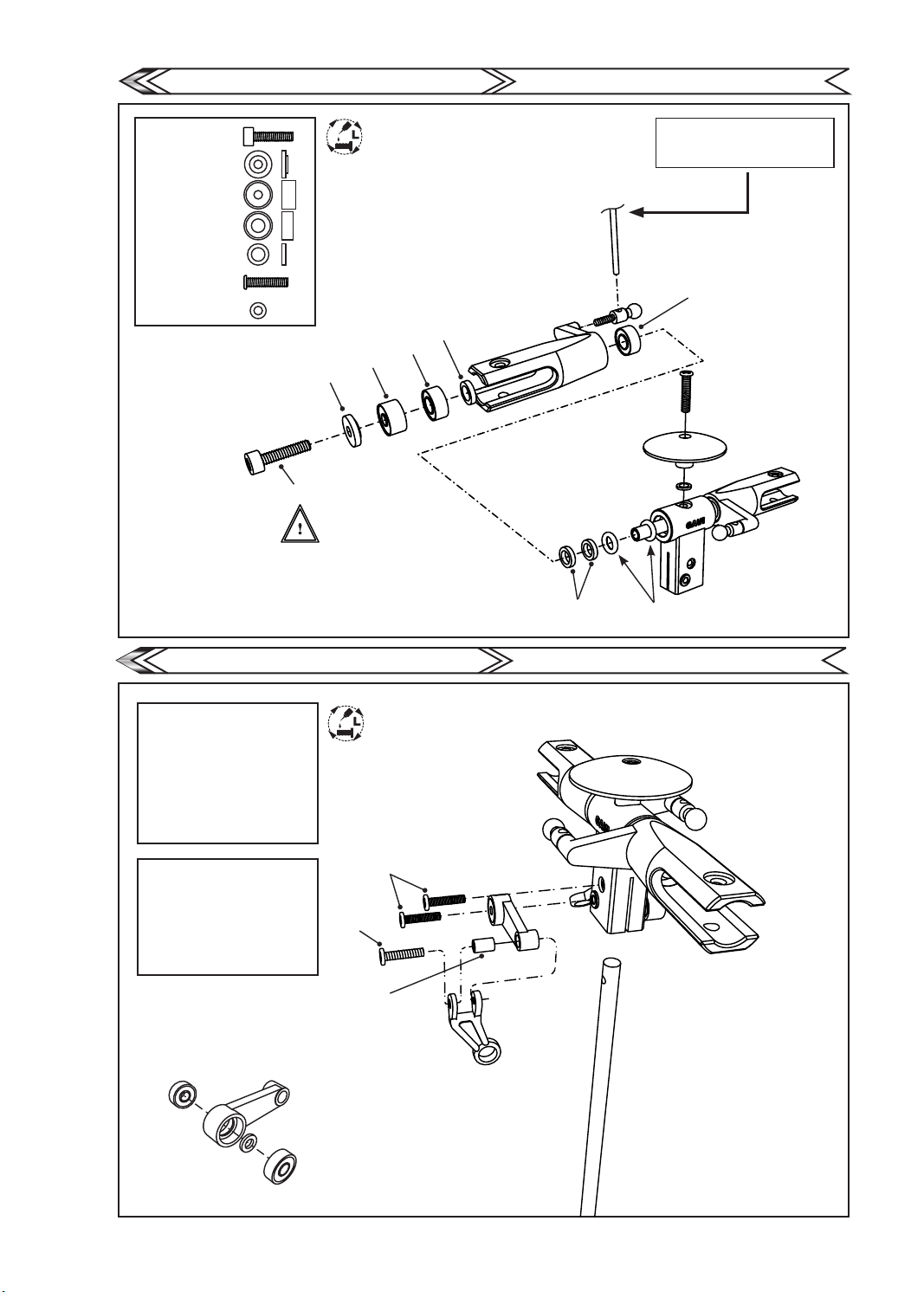
Rotor Blade Clamp Assembly
旋翼夾頭組裝
GAUI
TAI SHIH HOBBY CORPORATION
a.M2x8
b.W2x5.8x1.4
c.B2x6x3
d.B3x6x2.5
e.W3.1x4.6x1
f.M2x8.4
g.W2x3.5x0.5
b.W2x5.8x1.4
c.B2x6x3
a.M2x8
Apply thread lock on all
screws in this section.
螺絲均需上止滑劑
e.W3.1x4.6x1
d.B3x6x2.5
g.W2x3.5x0.5
e.W3.1x4.6x1
Tighten the ball link screw
using the screw driver
使用內附的六角板手將球頭旋緊。
d.B3x6x2.5
f.M2x8.4
Oring
Washout Arm Assembly
a.B1.5x4x1.2
b.W1.4x2.5x0.4
c.M1.4x6
d.Ø1.4x6
e.P1.4x2x3
1. Assembly Main Shaft and
Rotor Head.
2.When installing
d.Ø1.4x6
no need of thread lock.
1.將主軸組裝至旋翼頭。
2.組裝時
螺絲膠固定。
d.Ø1.4x6
不需使用
a.B1.5x4x1.2
b.W1.4x2.5x0.4
c.M1.4x6
d.Ø1.4x6
f.P1.4x2x3
a.B1.5x4x1.2
剪型臂組裝
Apply thread lock on all
screws in this section.
螺絲均需上止滑劑
GAUI
TAI SHIH HOBBY CORPORATION
9
Page 13
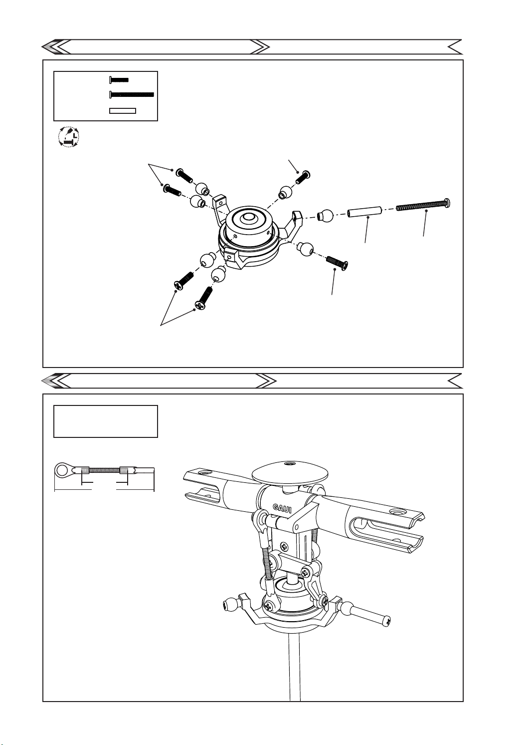
Swash Plate Assembly
a.M1.4x6
b.M1.4x15
c.P1.4x2x9.5
Apply thread lock on all
screws in this section.
螺絲均需上止滑劑
a.M1.4x6
十字盤組裝
GAUI
a.M1.4x6
TAI SHIH HOBBY CORPORATION
a.M1.4x6
Main Rotor Blade Ball Links Adjustment
1.製作兩支主旋翼拉桿並扣上。
Build two ball links
and insert in place.
x2
16mm
29.7mm
主旋翼拉桿配置
GAUI
c.P1.4x2x9.5
b.M1.4x15
a.M1.4x6
TAI SHIH HOBBY CORPORATION
10
Page 14
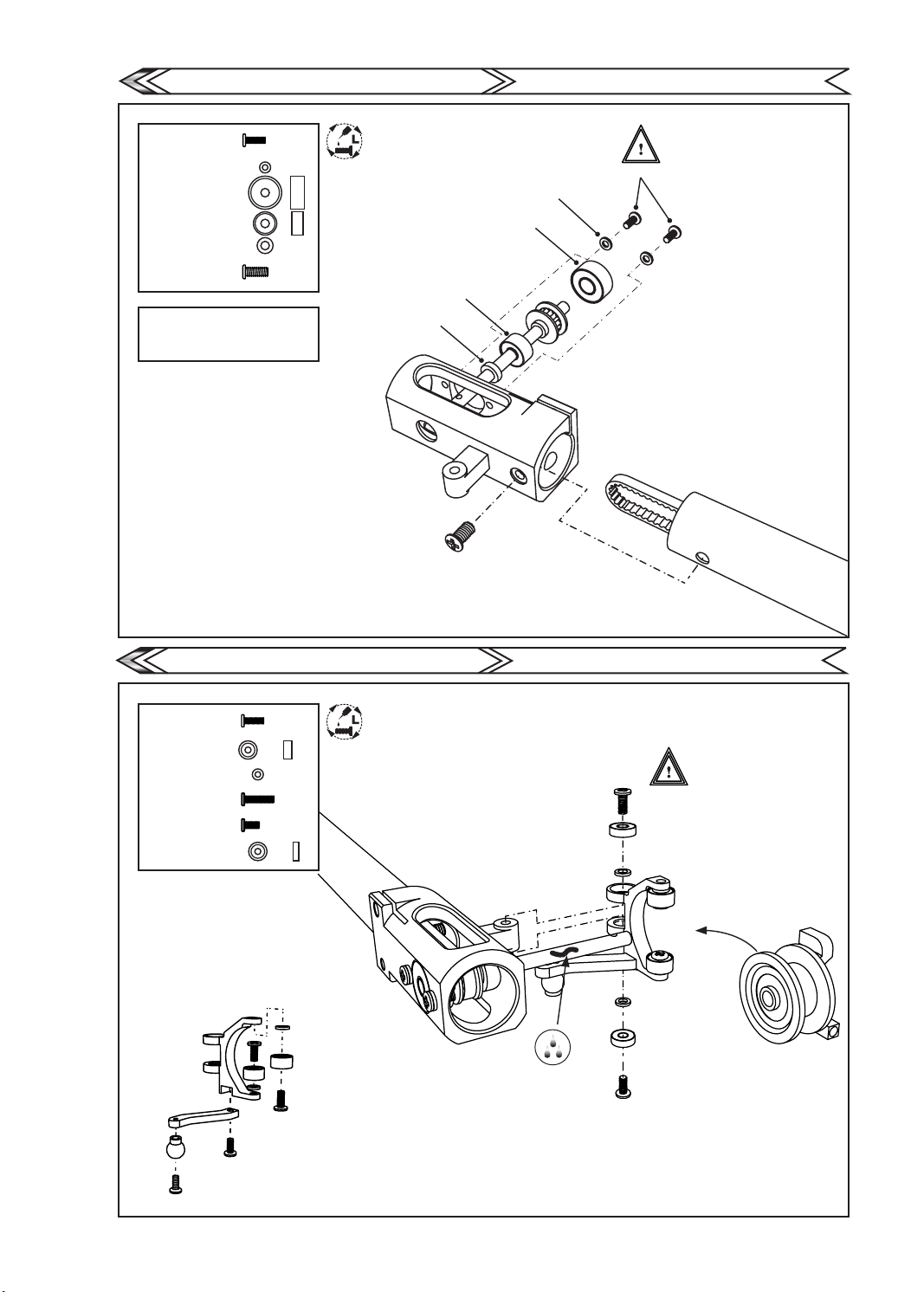
Tail Rotor Base Assembly
a.M1.4x4
b.W1.4x2.5x0.4
c.B2x7x3
d.B2x5x2.5
e.W2x3.5x1
f.M2x4.6
Insert belt into pulley of tail rotor
shaft and assemble tail rotor base
as described by exploded view.
將皮帶套入尾軸並如圖依序組裝。
尾殼組裝
Apply thread lock on all
screws in this section.
螺絲均需上止滑劑
d.B2x5x2.5
e.W2x3.5x1
b.W1.4x2.5x0.4
c.B2x7x3
f.M2x3.2
GAUI
TAI SHIH HOBBY CORPORATION
a.M1.4x4
Double link Tail Control Ass'y
a.M1.4x4
b.B1.5x4x2
c.W1.4x2.5x0.4
d.Ø1.4x6
e.M1.4x3
f.B1.5x4x1.2
a.M1.4x4
雙推系統組裝
Apply thread lock on all
screws in this section.
螺絲均需上止滑劑
c.W1.4x2.5x0.4
b.B1.5x4x2
a.M1.4x4
GAUI
TAI SHIH HOBBY CORPORATION
c.W1.4x2.5x0.4
e.M1.4x3
f.B1.5x4x1.2
c.W1.4x2.5x0.4
f.B1.5x4x1.2
e.M1.4x3
d.Ø1.4x6
11
Page 15
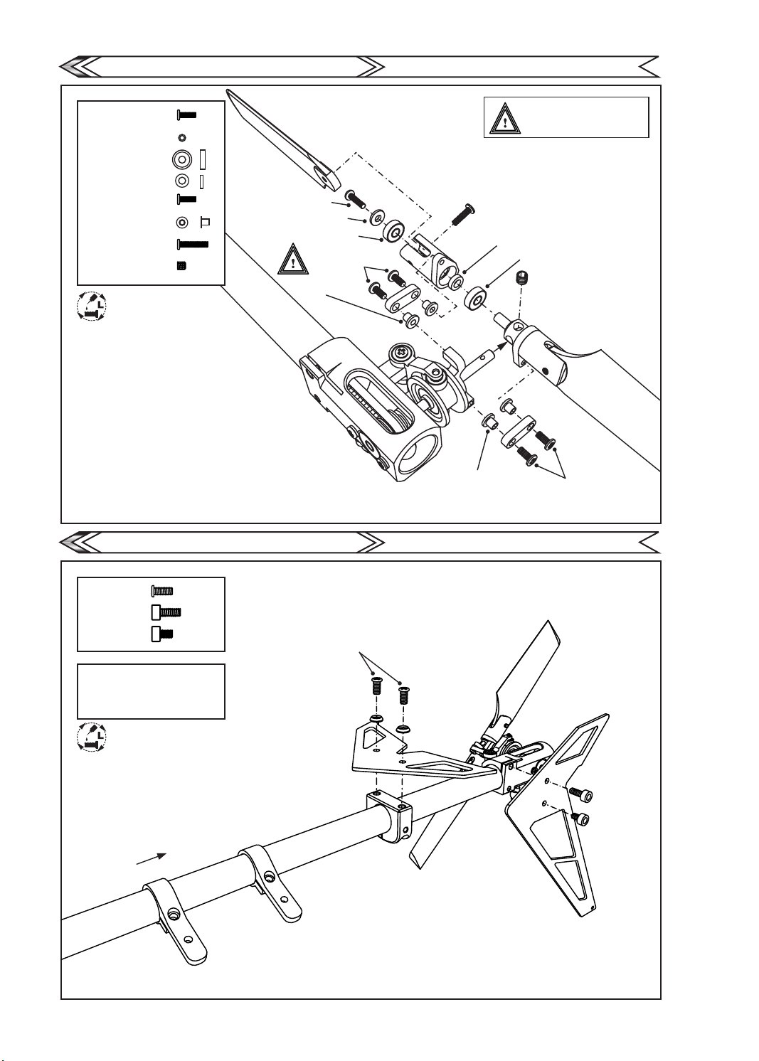
Tail Rotor Clamp Assembly
a.M1.4x5
b.W1.4x2x0.5
c.B2x5x1.5
d.P2x3.5x1
e.M1.4x4
f.P1.4x1.7x2.15
g.M1.4x7
h.M2x2
Apply thread lock on all
screws in this section.
螺絲均需上止滑劑
尾旋翼夾頭組裝
a.M1.4x5
b.W2x3.5x0.5
c.B2x5x1.5
e.M1.4x4
f.P1.4x1.7x2
GAUI
TAI SHIH HOBBY CORPORATION
Do not over tighten the
M1.4x4 screw
鎖緊e.M1.4x4時不可過份鎖緊。
g.M1.4x7
d.P2x3.5x1
c.B2x5x1.5
h.M2x2
Horizontal Tail Fin Installation
a.M2x4.6
b.M2x5
c.M2x3
Insert the horizontal n base and
servo base on the tail boom as
below exploded view.
將水平翼座及伺服機座置入尾管內
並以圖組裝。
Apply thread lock on all
screws in this section.
螺絲均需上止滑劑
尾翼組裝
a.M2x4.6
GAUI
f.P1.4x1.7x2
e.M1.4x4
TAI SHIH HOBBY CORPORATION
b.M2x5
c.M2x3
12
Page 16
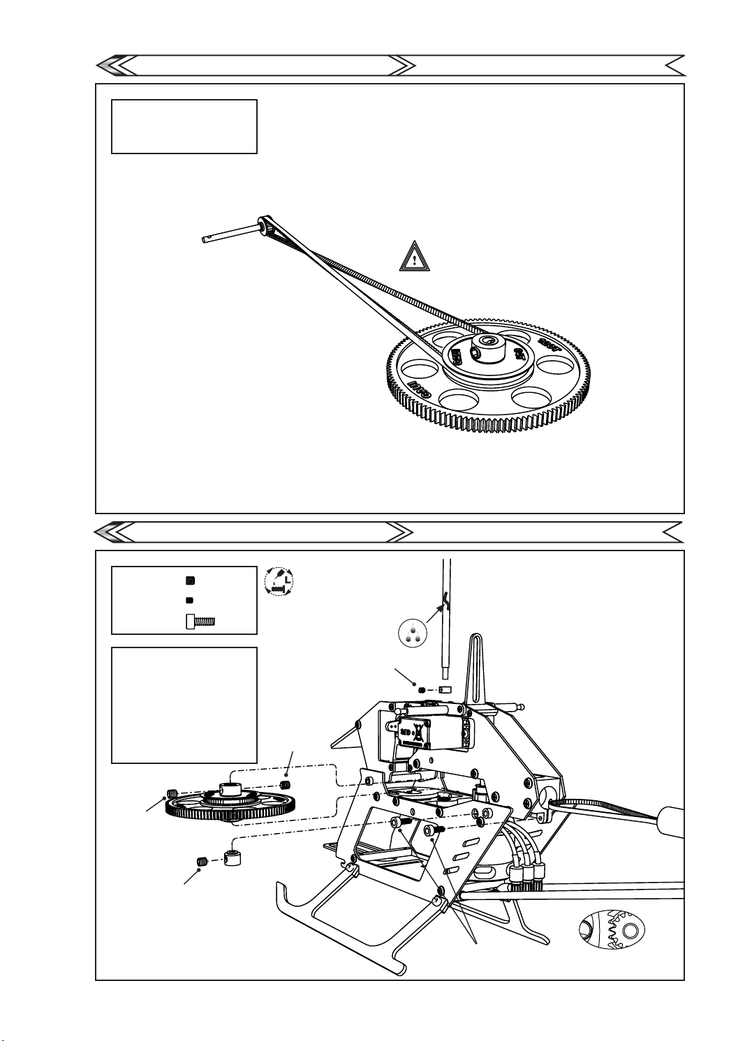
Belt Direction Check
When installing the tail boom
assembly. Please make sure the
direction and position of the belt.
安裝尾管總承時請確認皮帶方向無誤
不可纏繞
皮帶方向確認
GAUI
TAI SHIH HOBBY CORPORATION
Main Gear Installation
a.M3x3
b.M2x2
c.M2x5
1. Install the main gear and pull
back tail boom to adjust tightness
of belt before tightening
c.M2x5 screws.
2.Adjust carefully the
spacing between main gear and
motor gear to about 0.1mm
(gure 1-1).
1.組裝主齒盤並將尾管後拉調整
皮帶鬆緊度在鎖緊c.M2x5
2.仔細調整主齒盤與馬達齒間距
約0.1mm(圖1-1)。
a.M3x3
a.M3x3
主齒盤安裝
Apply thread lock on all
screws in this section.
螺絲均需上止滑劑
a.M3x3
b.M2x2
GAUI
TAI SHIH HOBBY CORPORATION
13
c.M2x5
(1-1)
Page 17
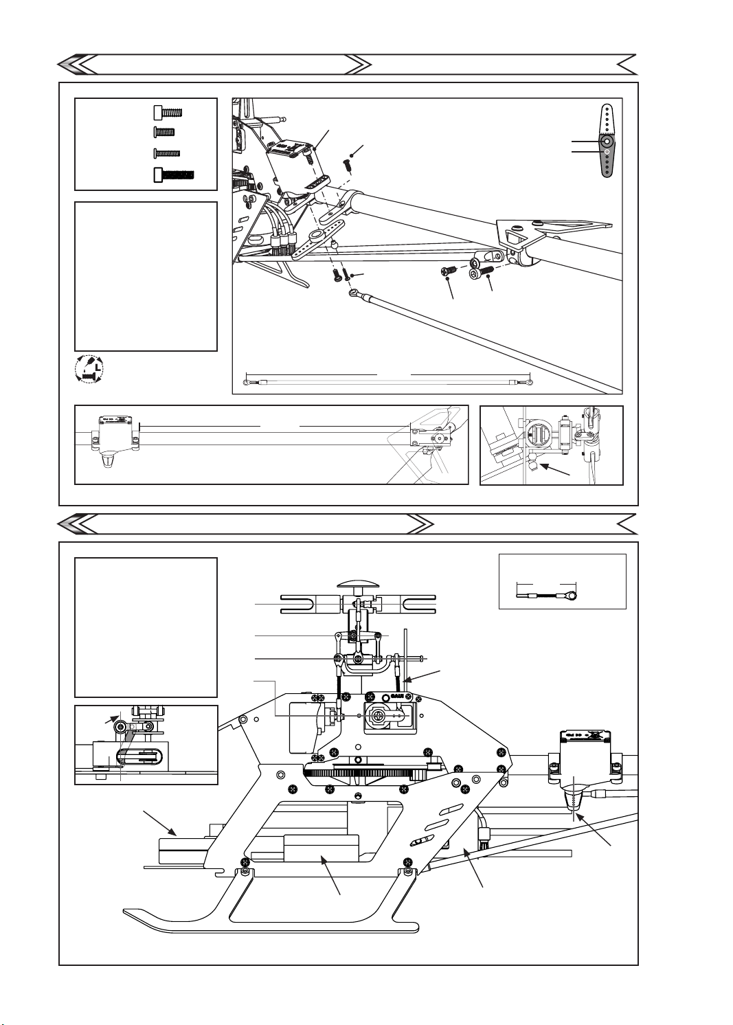
Tail Servo Assembly
尾伺服機組裝
GAUI
TAI SHIH HOBBY CORPORATION
a.M2x5
b.M2x4.6
c.M1.4x6
d.M2x8
1. Install tail servo and tail boom
support rods. Adjust tail servo
rod length.
2. Adjust position of servo base
(gure 1-1).
3. Adjust position of servo base
by turning around the
tail boom so that the
ball screw on the
servo horn is aligned (gure -2),
clip on the servo rod ball link.
1.組裝尾舵伺服機及支撐桿,
調整尾舵拉桿長度。
2.調整伺服器座位置(圖1-1)。
3.旋轉伺服機座使球頭呈同一直線
(圖1-2),扣上拉桿。
Apply thread lock on all
screws in this section.
螺絲均需上止滑劑
191.5 mm
a.M2x5
b.M2x4.6
c.M1.4x6
224 mm
b.M2x4.6
5mm
d.M2x8
(1-2)(1-1)
Electronics Setup / Check - 1
1.Check Main rotor clam is leveled.
2.Check washout Arm is leveled
horizontally.
3.Check swash plate is leveled
horizontally.
4.Check servo horn is leveled
horizontally.
5.Check Tail servo horn and arm
are perpendicular.
1.確認主旋翼夾頭水平。
2.確認剪型臂水平。
3.確認十字盤水平。
4.確認伺服機舵片水平。
5.確認尾舵伺機舵片與尾舵柄同
垂直。
5
Receiver
電裝配置/機構檢查-1
1
2
3
4
GYRO
GAUI
A
ESC
TAI SHIH HOBBY CORPORATION
All use the 16mm thread rod
皆使用16mm之全牙螺桿
31mm
A
5
14
Page 18
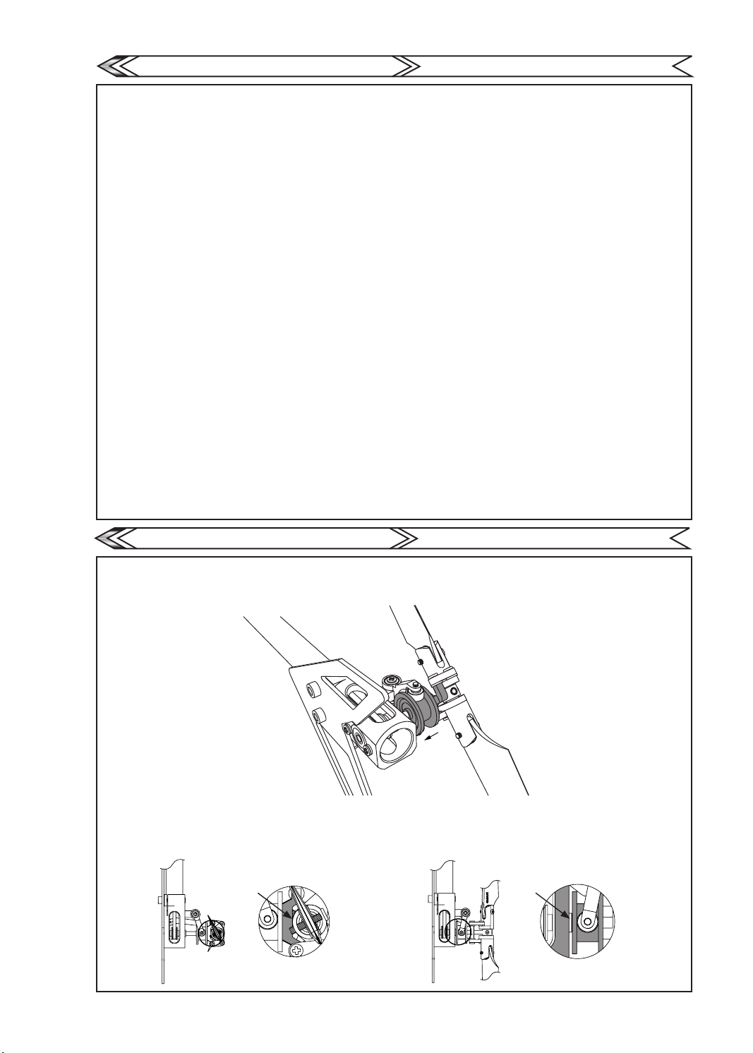
Check - 2
1.Move the throttle stick upward, check and make sure 3 linkages of swashplate all moved upward, if any one of the CCPM servos does not push up the
swash plate. Go to the transmitter setting to set Norm/Reverse to set the correct movement.
2.Move the AIL stick rightward, check and make sure the swashplate tilt to right side, if it tilt to the opposite side, set the “AIL %” in transmitter function “
Swash Mix ” to Negative value to make the swashplate move as your control. ( Ex. Set the “AIL +50%” to “AIL -50%” )
* Increase or decrease the “AIL %” to get the proper response of the AIL control.
3.Move the ELE stick forward, check and make sure the swashplate tilt forward, if it tilt to the opposite side, set the “ELE %” in transmitter function “
Swash Mix ” to Negative value to make the swashplate move as your control. ( Ex. Set the “ELE +50%” to “ELE -50%” )
* Increase or decrease the “ELE %” to get the proper response of the ELE control.
4.Set the transmitter function “ Subtrim ” to adjust the neutral position of CCPM servos, the servos at neutral should have the servo arms at level position,
and each arm should be perpendicular to the control linkage.
5.Move the throttle stick to the neutral (middle at 50% value), use a pitch gauge to check the pitch of both blades, adjust the linkages to make sure they
are all in 0 degrees of both blades.
6.The Servo Horns / Swash Plate / Washout Arms / should be set to be horizontally leveled as shown in gure.
7.Move the throttle stick to the top position, the maximum positive pitch should be around +11 to +13 degrees, If is is not the case, set the proper "Pitch%"
in the transmitter function "Swash Mix". Move the throttle stick down to the bottom position, the maximum negative pitch should be around -11 to -13
degrees, set the transmitter function “ Travel Volume / End Point “ properly to adjust to recommended negative pitch. IMPORTANT :
The increase/decrease value of the transmitter function “ Travel Volume / End Point “ of each CCPM servo should be the same in this step.
* Before starting step 8, make sure to move the control sticks to check the movement of the swashplate and set the proper “AIL % and ELE %”
in transmitter function “ Swash Mix ” to make sure each mechanism does not interfered with each other.
8.Move the throttle stick to the lowest position, set the proper “ Pitch Curve % ” in transmitter function “ Normal Mode ” to make the
negative collective pitcht to be -2 or -3 degrees at the lowest throttle stick position( it is about 40% to 45% at the 1st pitch curve point at normal mode).
The value of the middle point of pitch curve in normal mode is about 55% to 60%.
1.油門搖桿上推,確認連接3顆伺服機的十字盤是否同時向上移動,若無同時向上移動,請至搖控器選單設定【伺服機正反向設定】選項更改動作相反的
伺服機使十字盤同時向上移動。
2.向右撥動副翼搖桿,確認十字盤是否向右傾斜,若無向右傾斜,請至遙控器選單中SWASIA選項內的AIL(副翼)的%數更改為負值。
◎適當的增減數值可調整AILE動作量大小。
3.向前撥動升降搖桿,確認十字盤是否向前傾斜,若無向前傾斜,請至遙控器選單中SWASH選項內的【ELEV】升降的%數更改為負值。
◎適當的增減數值可調整ELEV動作量大小。
4.至遙控器選單中的【伺服機微調選項的 ”Subtrim ”功能】將十字盤3顆伺服機擺臂微調至垂直90度。
5.請將油門搖桿撥至中立,以螺距尺測量主旋翼的度數是否為0度。 若不是0度,請調整連桿長度使2支主旋翼均為0度。
6.調整3顆伺服機連桿長度至十字盤、相位器、皆水平。
7.請將油門搖桿向上撥至最高,測量主旋翼最大【正】螺距度數,應為+11至+13度。若不是,請調整遙控器選單中【SWASH】內的【PIT】數值。
請將油門搖桿向下撥至最低,測量主旋翼最大【負】螺距度數,應為-11至-13度。【正】【負】螺距度數需一樣若不是,請調整遙控器選單中的
【伺服機大小行程量】數值,三顆伺服機需同時增加或減少至測量結果與正螺距度數相同。
◎請、上、下、左、右、前、後撥動搖桿,查看十字盤行程動作是否有干涉。若有干涉請至SWASH減少AIL、ELE數值。
8.請將油門搖桿撥至最低點,測量主旋翼【負】螺距度數約在-2至-3度,並請進入遙控器選單中【PITCH曲線設定】選項,至【NORM模式】中增加數值最低
的數值,使主旋翼【負】螺距度數約在-2至-3度。【設定完的數值大約在40%至45%之間】至曲線設定中間的數值,增加數值至55至60%
機構檢查-2
GAUI
TAI SHIH HOBBY CORPORATION
Check - 3
1.Set the gyro to heading-hold mode, move the rudder stick rightward and make sure the tail pitch slider move toward the tail gear case, if it does not,
switch the transmitter function “ Servo Reverse ” of “ Rudder” to the opposite position.
請至遙控器設定選單中【陀螺儀感度GYRO】至鎖定狀態,向右撥動尾舵搖桿,尾軸滑套須向尾齒箱移動,若不是請調整遙控器選單中
【伺服機正反向設定】選項中【RUDD】的正反向。
2.Set the “ Limit ” on your gyro properly to have the maximum travel of tail pitch control, make sure the tail pitch slider at its maximum travel to left and
right should not touch the Tail Gear Case and Tail Hub, there should be a distance for 0.5mm( or less ) at each side.
Please follow your own gyro's instruction manual for adjustments.
設定尾舵左右最大行程量,左右最大行程量保持與尾齒箱及尾旋翼頭 0.5mm 距離不干涉為主。
(各廠牌陀螺儀行程量設定方法不同請參照陀螺儀說明書作設定)。
機構檢查-3
GAUI
TAI SHIH HOBBY CORPORATION
15
Page 19
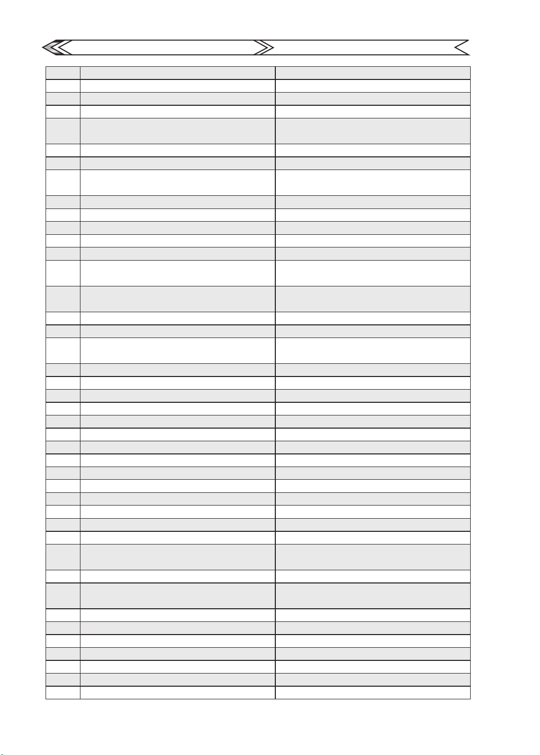
Upgrade & Replacement Parts
升級維修零件表
GAUI
TAI SHIH HOBBY CORPORATION
212003
212005
212100
212101
212102
212103
212104
212105
212106
212107
212109
212110
212111
212112
212113
212220
212221
212300
212301
212302
212303
212304
212305
212306
212307
212308
212309
212310
212311
212312
212313
212314
212315
212316
212317
212318
212319
212320
212321
212322
212323
212324
X2 Kit
X2 Super Combo
X2 CNC Stop Plate
X2 FES Rotor Head(Titanium anodized)
X2 CNC New FES Main Grips set for
H255(Titanium anodized)
Bearing(2x6x3)x2pcs
Bearing(3x6x2.5)x2pcs
X2 FES CNC Washout Arm Assembly
(Titanium anodized)
Bearing(1.5x4x1.2)x2pcs
X2 Spindles
X2 FES Main Shafts Pack (3x83.5mm)
X2 FES Rotor Head Pack
X2 CNC Swashplate Assembly
X2 Balls & Extension for CNC Swashplate
combo pack
X2 FES New 2Blade Head (3x83.5mm )
(Titanium anodized)
CF main blades (255L-CFA)
CF Main Rotor Blades (255L-Black)
Canopy Posts&X2 Damper Rubbers Pack
(for canopy)
X2 Canopy Post Stiffener(Alu black anodized)
X2 CNC Universal Battery Plate
X2 CNC Integrated Middle Mount
X2 CNC Front Servo Mount
X2 CF Upper Frames
X2 CF Lower Frames
X2 CF Landing Gear -Black
X2 FRP Painted Canopy(B Type)
X2 FRP White Canopy
X2 FRP Painted Canopy(A Type)
X2 FRP Painted Canopy(C Type)
X2 FRP Painted Canopy(D Type)
X2 CNC Swashplate Guide
X2 CF Landing Gear -(Black)
X2 Main Pulley Collars(for High Performance
Main Gear)
X2 Upper Mast Collar
One Way Bearing & Auto-rotation
Main Gear Set
X2 Swashplate Guide
X2 CNC Mast Mount
X2 CNC Motor Mount
Bearing(2x5x2.5)x3pcs
Bearing(3x6x2)x2pcs
B. for X2 Main Gear
X2 Aluminum Frame posts
X2 Kit
X2 Super Combo
X2 CNC煞車盤
X2 FES 主旋翼頭(電鍍鈦)
X2 CNC新無平衡桿主旋翼夾頭組(鈦色)
軸承包(2x6x3)x2個
軸承包(3x6x2.5)x2個
X2 FES CNC 剪型臂(電鍍鈦)
軸承包(1.5x4x1.2)x2個
X2 橫軸包
X2 FES 專用主軸(3x83.5mm)
X2 FES 旋翼頭連桿配件包
X2 CNC 十字盤組
X2球頭及延伸桿組合包
X2 FES 新型2槳無平衡桿旋翼頭(電鍍鈦)
碳纖槳 255L (CFA)
碳纖槳 255L(黑色)
X2艙罩支柱&橡膠減震包(座艙用)
X2 艙罩支柱強化版(鋁合金電鍍黑)
X2 CNC 萬用電池座
X2 CNC 一體成型主軸及尾管座
X2 CNC 前伺服機座
X 2 碳纖上側板組
X2 碳纖下側板組
X2 碳纖腳架組
X2 玻纖噴漆座艙(B型)
X2 玻纖黑白座艙組
X2 玻纖噴漆座艙(A型)
X2 玻纖噴漆座艙(C型)
X2 玻纖噴漆座艙(D型)
X2 CNC 十字盤滑軌
X2 碳纖腳架(黑)
X2 主皮帶輪固定環(高性能主齒盤用)
X2 上主軸固定環
高性能同步自旋主齒盤附單向軸承組
X2 十字盤滑軌
X2 CNC 主軸座
X2 CNC 馬達座
軸承包(2x5x2.5)x3個
軸承包(3x6x2)x2個
X2 主齒盤軸承包
X2 碳纖側板鋁柱包
16
Page 20
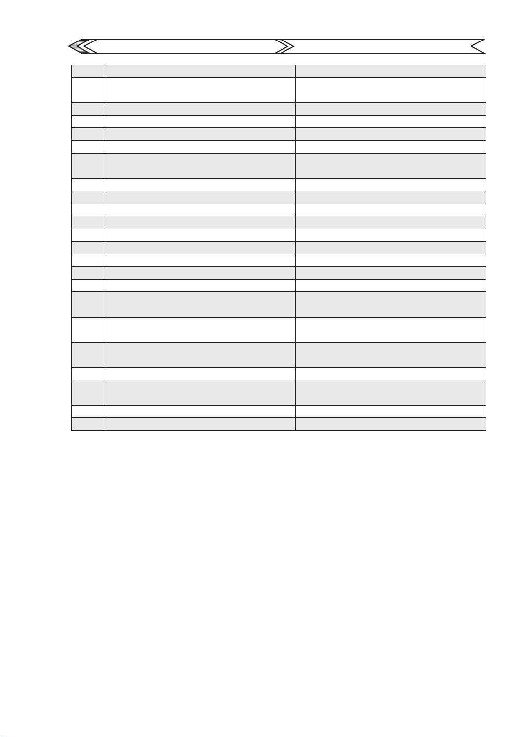
Upgrade & Replacement Parts
升級維修零件表
GAUI
TAI SHIH HOBBY CORPORATION
212324 X2 Aluminum Frame posts
212400
212401 Bearing(2x7x3)x2pcs
212402 X2 Tail Hub Set
212403 X2 CNC Tail Support Clamp
212404 X2 CNC Tail Servo Mount for Boom 9mm
212405
212406 X2 CNC Tail Rotor Grips(Titanium anodized)
212407 X2 CNC Tail Pitch Slider
212408 X2 Arc Tail Lever Set
212409 X2 CF Fin & Tail(A Type-Black)
212410 X2 High Performance Tail Rotor Blades(45mm)
212411 X2 Tail Boom Support Set
212412 X2 Black anodized Tail Booms Pack
212413 CF Tail Pushrod(CF rod 3x200mm)
212651 Washer Pack (W1.4x2.5x0.4)(P1.4X2X3)
212652
212653
212657
212663 Washer Pack(W3.1x5.5x1.1-W3.1x4.6x1)
212700
212715 Pinion Gear with Neck 15T(for 2.3mm shaft)
212726 Tail Rotor Belt(for X2 Series)
X2 CNC Tail Pulley and Output Shaft
Assembly(15T for belt version)
X2 CNC Integrated Tail Gear Case
(Black anodized)
Countsunk Washer and Machine
Screw set(M2x3.2)x10
Mechine Screws(M1.4x3)(M1.4x5)
(M1.4x6)(M1.4x7)
Machine Screws(M2x4.6)(M2x8.4)
(M2x5)(M2x2)
Blade Support&Cable Tie with Touch Fastener
(for X2)
X2 碳纖側板鋁柱包
X2 金屬尾齒輪組(15T皮帶版用)
軸承包(2x7x3)x2個
X2 尾旋翼頭
X2 CNC 水平尾翼及尾支撐桿座
X2 CNC 尾伺服機座(9mm尾管用)
X2 一體成型尾殼座組(電鍍黑)
X2 CNC 尾旋翼夾頭組(鈦色)
X2 CNC 雙推尾滑套
X2 雙推尾舵柄組
X2 碳纖尾翼組(A型-黑)
X2 高性能尾旋翼片組(45mm)
X2 尾支撐桿組
X2 黑色尾管包
碳纖維尾拉桿(3x200mm 碳纖桿 )
墊片包(W1.4x2.5x0.4)(P1.4X2X3)
沉頭墊片及螺絲組(M2X3.2)x10組
十字機械牙螺絲組(M1.4x3)(M1.4x5)(M1.4x6)
(M1.4x7)
機械牙螺絲組(M2x4.6)(M2x8.4)(M2x5)(M2x2)
墊片包(W3.1x5.5x1.1-W3.1x4.6x1)
主翼支撐墊&魔術束帶包(X2用)
長頸馬達齒15T(孔徑2.3mm)
尾傳動皮帶(X2系列用)
17
Page 21

Page 22

 Loading...