

Page 1
Replacing the AC Adapter
Re placing t he ACAdapter
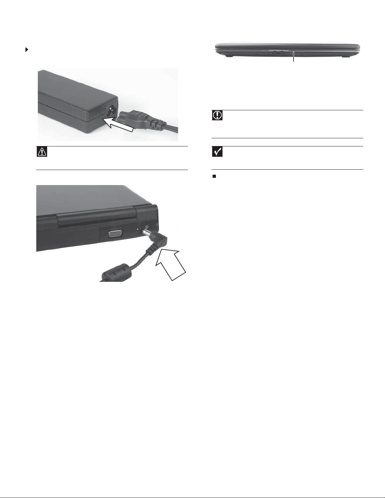
To connect the AC adapter:
1 Connect the power c ord to th e AC adapter.
3 Plug the power cord into an AC power outlet. The battery charge
indicator turns on.
Battery charge indicator
If the battery charge indicator does not turn on:
• Unp l u g t h e a d a p te r fr om you r n o te b o o k , th e n p l u g i t b ack i n .
•Press
• Make sure the power cord is firmly attached to the AC adapter.
• Plug the power cord into a different wall outlet.
FN+F1 to togg le th e s ta tu s l ig ht s o n a nd of f.
Warning
Do no t a ttem p t to d isas se m bl e th e AC ad a p ter. Th e AC a d a pte r h as
no user-replaceable or user-serviceable parts inside. The AC adapter has
dangerous voltages that can cause serious injury or death. Contact Gatewa y
about returning defective AC adapters.
1
Caution
Replace the power cord if it becomes damaged. The replacement
cord must be of the s ame type a nd voltage rating as the original cord or
your notebook may be damaged.
2 Connect the ACadapter to your notebook’s power connector.
Important
If the b a ttery ch a rge ind i c ator do es n ot tur n blue afte r th r e e ho u rs,
contact Gateway Customer Care at the Web address or telephone number
shown o n th e la bel on t he b ottom of you r n oteb ook .
Technical Support
See the label on the bottom of the notebook for Cu stomer Care Inf ormation. See
your Reference Guide for important safety, regulat ory, a nd legal information.
© 2008 Gateway , Inc. All rights reserved. Gate wa y and eMachines are trademarks
or registered trademarks of Gatewa y ,Inc. in the United States and other countries.
All other brands and product names are trademarks or registered trademarks of
their respecti ve companies.
Page 2
Replacing the Battery
1
Re placing t he Batt ery
Important
If your notebook is connected to AC power, you can replace the
batter y wh il e you r no tebo ok is tu rne d o n.
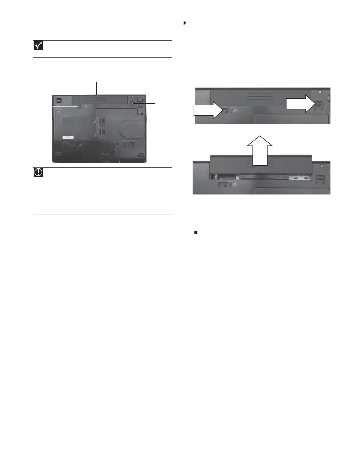
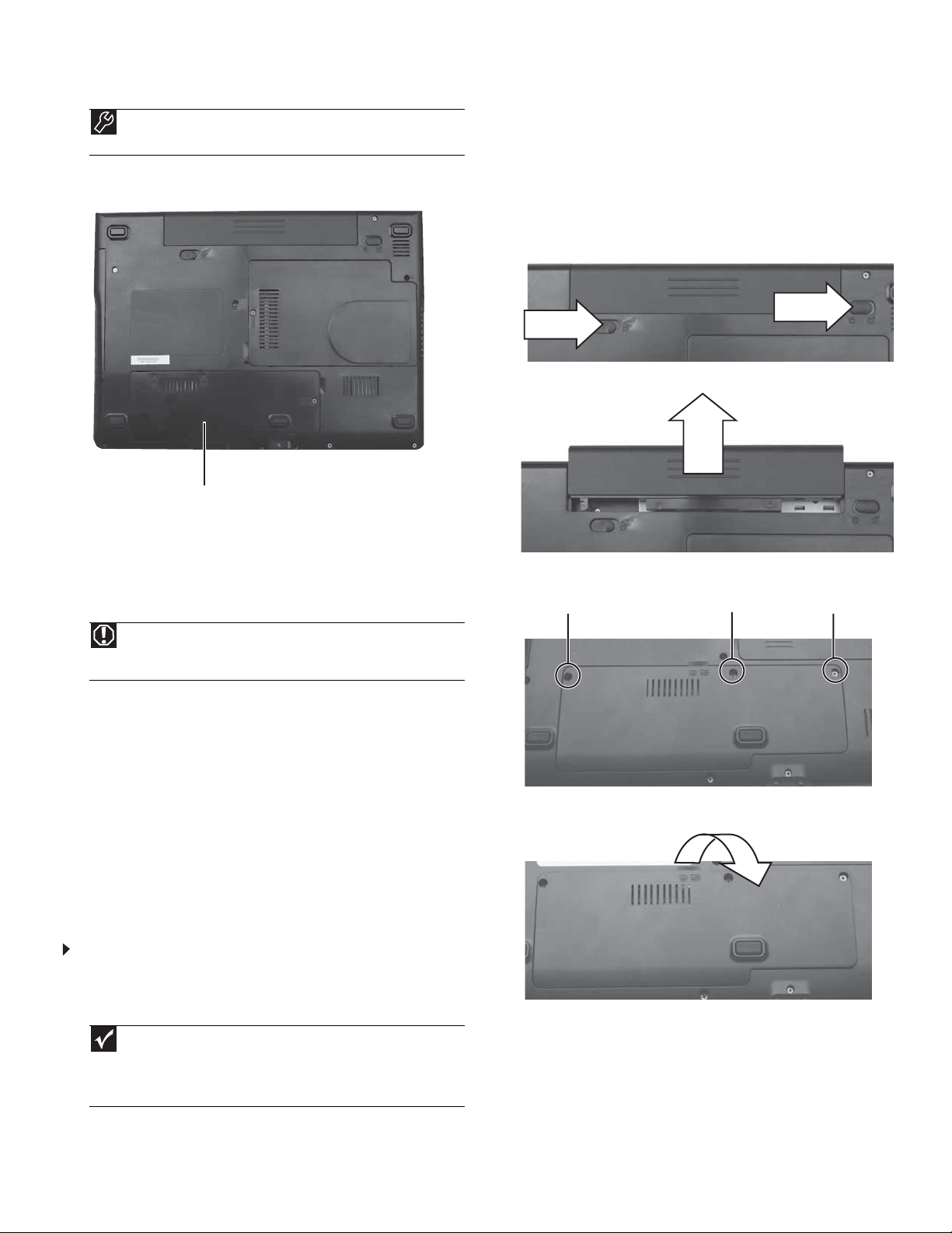
Locating C omponents
Battery
Battery
latch
Warning
Danger of explosion if the battery is incorrectly replaced.
Repla ce on ly w ith a b atte r y sp e cifi ca lly ma nu fact ur ed fo r yo ur no teb oo k.
Recycle or dispose of the battery as hazardous waste.
The battery used in this device may present a fire or chemical burn hazard
if mishandled. Do not disassemble, heat above 212°F (100°C), or incinerate.
Keep away fro m ch ild ren .
Battery
lock
To repla ce the b atte ry:
1 If your notebook is on and is connected to AC power, go to Step 2.
-ORIf your not ebook is on and is not co nnect ed t o A C po w er, sa v e you r
work and turn off your notebook.
2 Turn your notebook over so the bottom is facing up.
3 Slide the battery lock to the unlocked position, then slide the
batte r y l atc h.
4 Slide the battery out of your notebook.
5 Slide a recharged battery into your notebook until it snaps into
place.
6 Slide the ba ttery lock to the lo cked pos itio n.
7 Turn your notebook over.
8 Open the LCD panel.
Technical Support
See the label on the bottom of the notebook for Cu stomer Care Inf ormation. See
your Reference Guide for important safety, regulat ory, a nd legal information.
© 2008 Gateway , Inc. All rights reserved. Gate wa y and eMachines are trademarks
or registered trademarks of Gatewa y ,Inc. in the United States and other countries.
All other brands and product names are trademarks or registered trademarks of
their respecti ve companies.
Page 3
Replacing the DVD drive
1
Re placing t he DV D driv e
Tools
You need a small Phillips screwdriver to replace the DVD drive.
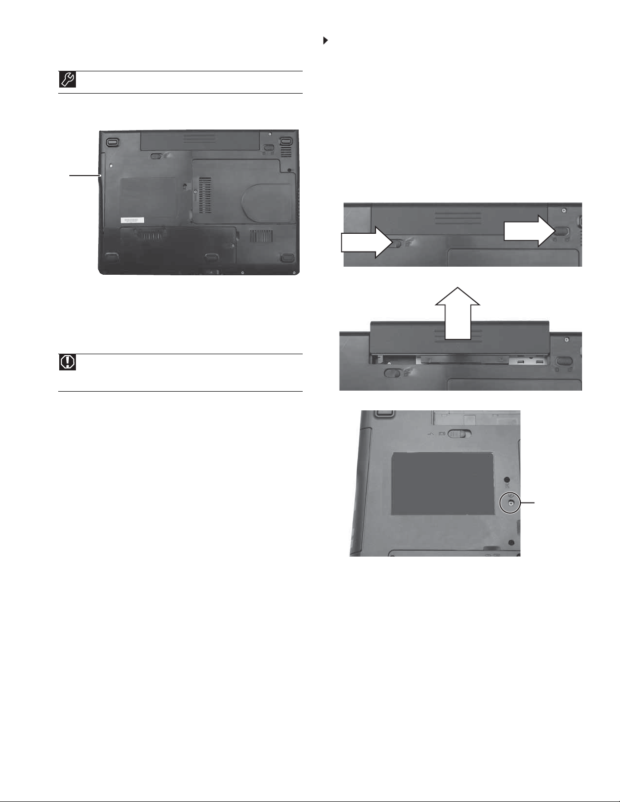
Locating C omponents
DVD
drive
Prev enting static elec tric ity dischar ge
The components inside your notebook are extremely sensitive to static
electricity, also known as electrostatic discharge (ESD). ESD can
permanently damage electrostatic discharge-sensitive components in
your no te bo ok .
To replace the DVD drive:
1 Follow the guidelines under “Preventing static electricity
discharge.”
2 Make sure that the DVD drive is empty.
3 Turn off your notebook.
4 Close the LCD panel.
5 Disconnect the AC adapter, modem cable, and network cable.
6 Disconnec t all pe riphe ra l de v ice s conne c t ed t o y ou r not e book and
remove any Express and memory cards.
7 Turn your notebook over so the bottom is facing up.
8 Slide the battery lock to the unlocked position, then slide the
batte r y l atc h.
9 Slide the battery out of your notebook.
Warning
To avoid exposure to dangerous electrical voltages and moving
parts, turn off your notebook and unplug the AC adapter, modem cable,
and network cable and remove the battery before replacing a component.
Before working with notebook components, follow these guidelines:
• Avoid static-causing surfaces such as carpeted floors, plastic,
and packing foam.
• Remov e components from their antistatic bags only when you
are ready to use them. Do not lay components on the outside
of antistatic bags because only the inside of the bags provide
electrostatic protection.
• Always hold components by their edges. Avoid touching the
edge connectors. Never slide components over any surface.
• Wear a grounding wrist strap (available at most electronics
stores) and attach it to a bare metal part of your workbench
or other grounded connection.
• Touch a bare metal surface on your workbench or other
grounded object.
10 Remove the screw tha t secures th e DVD d rive to your n oteb ook.
Screw
Technical Support
See the label on the bottom of the notebook for Cu stomer Care Inf ormation. See
your Reference Guide for important safety, regulat ory, a nd legal information.
© 2008 Gateway , Inc. All rights reserved. Gate wa y and eMachines are trademarks
or registered trademarks of Gatewa y ,Inc. in the United States and other countries.
All other brands and product names are trademarks or registered trademarks of
their respecti ve companies.
Page 4
Replacing the DVD drive
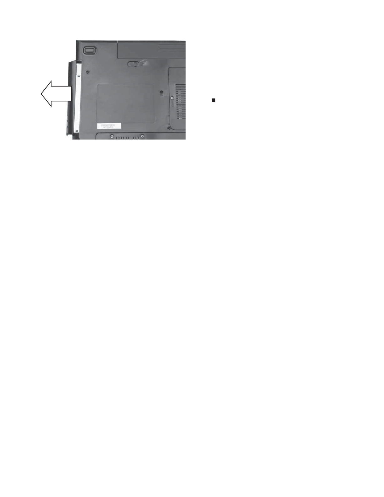
1 1 Carefully slide the drive out of the drive bay. 12 Slide the ne w DVD driv e into t he drive ba y . Make sure t hat the driv e
fits secu rely i n the b ay.
13 Replace the screw removed in Step10.
14 Slide the battery into your notebook until it snaps into place.
15 Slide the battery lock to the locked position.
16 Turn your notebook over.
17 Connect the power adapter, modem cable, and network cable.
18 Reconnect all peripheral devices and replace any Express and
memory cards.
19 Turn on your notebook.
2
Technical Support
See the label on the bottom of the notebook for Cu stomer Care Inf ormation. See
your Reference Guide for important safety, regulat ory, a nd legal information.
© 2008 Gateway , Inc. All rights reserved. Gate wa y and eMachines are trademarks
or registered trademarks of Gatewa y ,Inc. in the United States and other countries.
All other brands and product names are trademarks or registered trademarks of
their respecti ve companies.
Page 5
Replacing the hard drive
Re placing t he hard dr iv e
Tools
You need a small Phillips screwdriver to replace the hard drive. You
also need the operating system disc that came with your n otebook.
Locating C omponents
1
2 Follow the guidelines under “Preventing static electricity
discharge.”
3 Turn off your notebook.
4 Close the LCD panel.
5 Disconnect the AC adapter, modem cable, and network cable.
6 Disconnect all peripheral devices connec t e d to y our notebook and
remove any Express and memory cards.
7 Turn your notebook over so the bottom is facing up.
8 Slid e the battery lock to the unlocked position, then slide the
batte r y l atc h.
9 Slide the battery out of your notebook.
Hard drive bay
Prev enting static elec tric ity dischar ge
The components inside your notebook are extremely sensitive to static
electricity, also known as electrostatic discharge (ESD). ESD can
permanently damage electrostatic discharge-sensitive components in
your no te bo ok .
Warning
To avoid exposure to dangerous electrical voltages and moving
parts, turn off your notebook and unplug the AC ada pter, modem cable,
and network cable and remove the battery before replacing a component.
Before working with notebook components, follow these guidelines:
• Avoid static-causing surfaces such as carpeted floors, plastic,
and packing foam.
• Remov e components from their antistatic bags only when you
are ready to use them. Do not lay components on the outside
of antistatic bags because only the inside of the bags provide
electrostatic protection.
• Always hold components by their edges. Avoid touching the
edge connectors. Never slide components over any surface.
• Wear a grounding wrist strap (available at most electronics
stores) and attach it to a bare metal part of your workbench
or other grounded connection.
• Touch a bare metal surface on your workbench or other
grounded object.
10 Loosen the thr ee hard dri ve ba y cov er scr ew s (thes e scre ws cannot
be removed).
ScrewScrew Screw
11 Lift the hard drive bay cover using the thumb notch, then remove
it.
To replace the hard drive:
1 If possible, create a Drivers and Applications Recovery disc. For
more informat ion , see “Prep ari ng for soft ware and device driver
recovery” in the Re feren ce Gu id e.
Important
If you cannot create a Drivers and Applications Recovery disc,
Gateway may s end you a set of reco v ery discs or a replacement hard drive
with the drivers and applications already installed. Contact Gateway
Customer Care at the Web address or telephone number shown on the label
on the botto m of you r no tebo ok .
Technical Support
See the label on the bottom of the notebook for Cu stomer Care Inf ormation. See
your Reference Guide for important safety, regulat ory, a nd legal information.
© 2008 Gateway , Inc. All rights reserved. Gate wa y and eMachines are trademarks
or registered trademarks of Gatewa y ,Inc. in the United States and other countries.
All other brands and product names are trademarks or registered trademarks of
their respecti ve companies.
Page 6

Replacing the hard drive
12 Remove the two screws connecting the hard drive to your
notebook.
Screw
13 Using the plastic tab, slide the old hard drive, then remove it.
14 Remov e the four s crew s that secur e the hard dri ve to the har d drive
bracket.
Screw
2
15 Remove th e bracket from the ol d drive.
16 Pla ce the new drive, lab el si de up, onto th e bracket so the screw
holes line up.
17 Replace the screws removed in Step14.
18 Slide the new hard drive kit into your notebook.
19 Replace the screws removed in Step12.
20 Replace the ha rd drive b ay cover, then ti ghten th e cover screws.
21 Slide the battery into your notebook until it snaps into place.
22 Slide the battery lock to the locked position.
23 Turn your notebook over.
24 Connect the power adapter, modem cable, and network cable
25 Turn on your notebook, open the DVD drive, insert the Windows
DVD, cl ose the DV D d rive, t he n re sta rt you r n ote bo ok .
26 When the prompt “Press any key to boot from CD or DVD” appears,
press any key on your keyboard and follow the on-screen
instructions . As part of t he pr oces s y ou ma y be promp te d to ins ert
your Drivers and Applications Recovery disc.
27 Reconnect all peripheral devices and replace any Expresscards.
Screw
Screw
Screw
Screw
Technical Support
See the label on the bottom of the notebook for Cu stomer Care Inf ormation. See
your Reference Guide for important safety, regulat ory, a nd legal information.
© 2008 Gateway , Inc. All rights reserved. Gate wa y and eMachines are trademarks
or registered trademarks of Gatewa y ,Inc. in the United States and other countries.
All other brands and product names are trademarks or registered trademarks of
their respecti ve companies.
Page 7

Replacing the keyboard
Re placing t he ke y board
1
9 With a small Phillips screwdriver, remove the keyboard screw and
put it in a safe place.
Tools
You need a small Phillips and a small flat-blade screwdriver to
replace the keyboard.
Prev enting static elec tric ity dischar ge
The components inside your notebook are extremely sensitive to static
electricity, also known as electrostatic discharge (ESD). ESD can
permanently damage electrostatic discharge-sensitive components in
your no te bo ok .
Warning
To avoid exposure to dangerous electrical voltages and moving
parts, turn off your notebook and unplug the AC ada pter, modem cable,
and network cable and remove the battery before replacing a component.
Before working with notebook components, follow these guidelines:
• Avoid static-causing surfaces such as carpeted floors, plastic,
and packing foam.
• Remov e components from their antistatic bags only when you
are ready to use them. Do not lay components on the outside
of antistatic bags because only the inside of the bags provide
electrostatic protection.
• Always hold components by their edges. Avoid touching the
edge connectors. Never slide components over any surface.
• Wear a grounding wrist strap (available at most electronics
stores) and attach it to a bare metal part of your workbench
or other grounded connection.
• Touch a bare metal surface on your workbench or other
grounded object.
Important
The keyboard screw hole is marked with a K.
Screw
10 Turn your noteb ook over so the top is facing up.
11 Open the LCD panel to the fully opened position.
12 Insert the small flat-blade screwdriver under the left end of the
keyboard cover and gently pry it up.
13 Pull the co ver of f your not ebook. Be careful t o not damage the L CD
panel.
Caution
Depending on the k e y boar d co v er ty p e , t he co v er may be connect ed
to your notebook by a cable. Do not disconnect the cable from the cover
or notebook.
To replace the keyboard:
1 Follow the guidelines under “Preventing static electricity
discharge.”
2 Turn off your notebook.
3 Close the LCD panel.
4 Disconnect the AC adapter, modem cable, and network cable.
5 Disconnect all peripheral devices co nnec t ed to your not ebook and
remove any Express and memory cards.
6 Turn your notebook over so the bottom is facing up.
7 Slide the ba ttery l ock to t he un locked posit ion, then sli de the
battery latch.
8 Slide the battery out of your notebook.
-OR-
14 With a s mall P hillip s sc r e w dr iv e r, r emo ve the tw o ke ybo ard s c rews
and put them in a safe place.
Screw
Screw
Technical Support
See the label on the bottom of the notebook for Cu stomer Care Inf ormation. See
your Reference Guide for important safety, regulat ory, a nd legal information.
© 2008 Gateway , Inc. All rights reserved. Gate wa y and eMachines are trademarks
or registered trademarks of Gatewa y ,Inc. in the United States and other countries.
All other brands and product names are trademarks or registered trademarks of
their respecti ve companies.
Page 8

Replacing the keyboard
15 Lift the back edge of the keyboard slightly, then slowly slide it
toward the LCD panel to rele ase the keyboard retain ing t abs
located on the front edge of the keyboard.
2
20 Insert the ta bs on the front edge of th e keyboard in to the s lots
under the palm res t. Y ou ma y need to pr ess down on t he ke ybo ard
keys along the front e dge of the keyboa rd to sea t the ret ain ing
tabs into their corresponding slots.
16 Slide the brown keyboard connector clips to the back of your
notebook, then slide the cable out of the clips. Be careful not to
touch or damage any other components.
Clip
Clip
17 R e m o v e t he o l d k ey b oa r d .
18 Place the new k eyboard k eys-up on y our not eboo k wi th the sp ace
bar toward you.
19 Make sure the brown keyboard connector clips are fully moved
toward the back of your notebook, insert the cable into the
connect or , then sli de th e brow n c lips t o lo ck the connect or i n place .
Important
The keyboard cable is correctly oriented if it is not twisted.
21 Gently press the keyboard down until it is flat all the way across.
The keyboard should easily fall into place. Be careful to not
damage the LCDpanel.
22 Replace the screws removed in Step 14.
23 Rep lac e t he keyboa rd c over. P ress dow n o n th e c over in severa l
places until it clicks in place. Th e cover is corre ctly mount e d w h en
you can run your finger along the cover and find no loose spots.
The cover should be flat all the way across.
Caution
If the cover is not correctly replaced, your notebook could be
damaged when you try to close the LCD panel.
24 Clos e th e LCD pa ne l.
25 Turn your notebook over so the bottom is facing up.
26 Replace the screw removed in Step 9.
27 Slide the battery into your notebook until it snaps into place.
28 Slide the battery lock to the locked position.
29 Turn your notebook over.
30 Connect the power adapter, modem cable, and network cable
31 Reconnect all peripheral devices and replace any Express cards.
Technical Support
See the label on the bottom of the notebook for Cu stomer Care Inf ormation. See
your Reference Guide for important safety, regulat ory, a nd legal information.
© 2008 Gateway , Inc. All rights reserved. Gate wa y and eMachines are trademarks
or registered trademarks of Gatewa y ,Inc. in the United States and other countries.
All other brands and product names are trademarks or registered trademarks of
their respecti ve companies.
Page 9

Replacing a Memory Mod ule
1
Re placing a Memory Module
Tools
You need a small Phillips screwdriver to replace a memory module.
Locating C omponents
Memory
bay
Prev enting static elec tric ity dischar ge
The components inside your notebook are extremely sensitive to static
electricity, also known as electrostatic discharge (ESD). ESD can
permanently damage electrostatic discharge-sensitive components in
your no te bo ok .
To replace a memory module:
1 Follow the guidelines under “Preventing static electricity
discharge.”
2 Turn off your notebook.
3 Close the LCD panel.
4 Disconnect the AC adapter, modem cable, and network cable.
5 Disconnect all peripheral devices connected t o y our notebook and
remove any Express and memory cards.
6 Turn your notebook over so the bottom is facing up.
7 Slid e the battery lock to the unlocked position, then slide the
batte r y l atc h.
8 Slide the battery out of your notebook.
Warning
To avoid exposure to dangerous electrical voltages and moving
parts, turn off your notebook and unplug the AC ada pter, modem cable,
and network cable and remove the battery before replacing a component.
Before working with notebook components, follow these guidelines:
• Avoid static-c ausing surfaces such as carpeted floors, plastic,
and packing foam.
• Remov e components from their antistatic bags only when you
are ready to use them. Do not lay components on the outside
of antistatic bags because only the inside of the bags provide
electrostatic protection.
• Always hold components by their edges. Avoid touching the
edge connectors. Never slide components over any surface.
• Wear a grounding wrist strap (available at most electronics
stores) and attach it to a bare metal part of your workbench
or other grounded connection.
• Touch a bare metal surface on your workbench or other
grounded object.
9 Loosen the memory bay cover screw (this screw cannot be
removed).
Screw
10 Lift the memory bay cover, then remove it.
Technical Support
See the label on the bottom of the notebook for Cu stomer Care Inf ormation. See
your Reference Guide for important safety, regulat ory, a nd legal information.
© 2008 Gateway , Inc. All rights reserved. Gate wa y and eMachines are trademarks
or registered trademarks of Gatewa y ,Inc. in the United States and other countries.
All other brands and product names are trademarks or registered trademarks of
their respecti ve companies.
Page 10
Replacing a Memory Mod ule
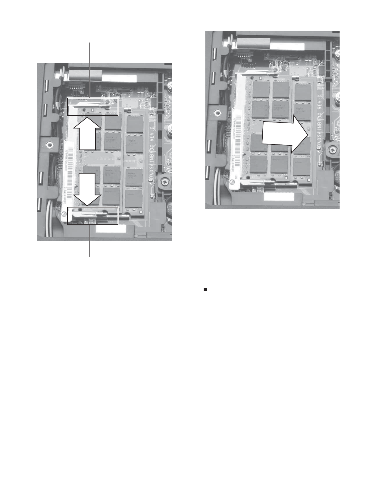
11 If you are remov ing a module, gently press outward on the clip at
each end of the memory module until the module tilts upward.
Clip
2
12 Pull the memory mod ule out of the slo t.
Clip
13 Hold the new or replacement module at a 30-degree angle and
press it into the em pty memo ry slot. T his module is k e y ed so it can
only be inserted in one direction. If the module does not fit, make
sure tha t the n otch in th e mo dule lines up with the t ab in the
memory bay.
14 Repla ce the mem ory bay cover, then t igh ten the c over screw.
15 Slide the battery into your notebook until it snaps into place.
16 Slide the battery lock to the locked position.
17 Turn your notebook over.
18 Connect the power adapter, modem cable, and network cable
19 Reconnect all peripheral devices and replace any Express cards.
Technical Support
See the label on the bottom of the notebook for Cu stomer Care Inf ormation. See
your Reference Guide for important safety, regulat ory, a nd legal information.
© 2008 Gateway , Inc. All rights reserved. Gate wa y and eMachines are trademarks
or registered trademarks of Gatewa y ,Inc. in the United States and other countries.
All other brands and product names are trademarks or registered trademarks of
their respecti ve companies.
Page 11

Replacing the Multimedi a Keyboard Cover
Replac ing the Multimedia
1
9 With a small Phillips screwdriver, remove the keyboard screw and
put it in a safe place.
Keyboard Cover
Tools
You need a small Phillips and a small flat-blade screwdriver to
replace the multimedia keyboard cover.
Prev enting static elec tric ity dischar ge
The components inside your notebook are extremely sensitive to static
electricity, also known as electrostatic discharge (ESD). ESD can
permanently damage electrostatic discharge-sensitive components in
your no te bo ok .
Warning
To avoid exposure to dangerous electrical voltages and moving
parts, turn off your notebook and unplug the AC ada pter, modem cable,
and network cable and remove the battery before replacing a component.
Before working with notebook components, follow these guidelines:
• Avoid static-c ausing surfaces such as carpeted floors, plastic,
and packing foam.
• Remov e components from their antistatic bags only when you
are ready to use them. Do not lay components on the outside
of antistatic bags because only the inside of the bags provide
electrostatic protection.
• Always hold components by their edges. Avoid touching the
edge connectors. Never slide components over any surface.
• Wear a grounding wrist strap (available at most electronics
stores) and attach it to a bare metal part of your workbench
or other grounded connection.
• Touch a bare metal surface on your workbench or other
grounded object.
Important
The keyb oard screw hole is marked with a K.
Screw
10 Turn your noteb ook over so the top is facing up.
11 Open the LCD panel to the fully opened position.
12 Insert the small flat-blade screwdriver under the left end of the
keyboard cover and gently pry it up.
13 Pull the co ver of f your not ebook. Be careful t o not damage the L CD
panel.
Caution
The cover is connected to your notebook by a cable. Do not pull on
the ca bl e.
To replace the multimedia keyboard cover:
1 Follow the guidelines under “Preventing static electricity
discharge.”
2 Turn off your notebook.
3 Close the LCD panel.
4 Disconnect the AC adapter, modem cable, and network cable.
5 Disconnect all peripheral devices connected t o y o ur not ebook and
remove any Express and memory cards.
6 Turn your notebook over so the bottom is facing up.
7 Slide the ba ttery l ock to t he un locked posit ion, then sli de the
battery latch.
8 Slide the battery out of your notebook.
-OR-
14 With a s mall P hillip s sc r e w dr iv e r, remove the tw o keyboard s cr e w s
and put them in a safe place.
Screw
Screw
Technical Support
See the label on the bottom of the notebook for Cu stomer Care Inf ormation. See
your Reference Guide for important safety, regulat ory, a nd legal information.
© 2008 Gateway , Inc. All rights reserved. Gate wa y and eMachines are trademarks
or registered trademarks of Gatewa y ,Inc. in the United States and other countries.
All other brands and product names are trademarks or registered trademarks of
their respecti ve companies.
Page 12

Replacing the Multimedi a Keyboard Cover
15 Lift the back edge of the keyboard slightly, then slowly slide it
toward the LCD panel to rele ase the keyboard retain ing t abs
located on the front edge of the keyboard.
2
20 Insert the ta bs on the front edge of th e keyboard in to the s lots
under the palm res t. Y ou ma y need to pr ess down on t he ke ybo ard
keys along the front e dge of the keyboa rd to sea t the ret ain ing
tabs into their corresponding slots.
16 Slowly r otat e the k eyboard towar d y ou s o it lie s k eys-down on t op
of your notebook. Be careful to not damage the LCD panel.
Caution
The keyboard is connected to your notebook by a cable. Do not
disconnect the cable from your notebook.
17 Lift t he br ow n multim edia k e y boar d cov er c onnec tor c lip o ff o f the
cable. Be careful not to touch or damage any other components.
21 Gently press the keyboard down until it is flat all the way across.
The keyboard should easily fall into place. Be careful to not
damage the LCDpanel.
22 Replace the screws removed in Step 14.
23 Replace the multimedia keyboard cover. Press down on the cover
in several places until it clicks in place. The cover is correctly
mounted when you can run your finger along the cover and find
no loose spots. The cover should be flat all the way across.
Caution
If the cover is not correctly replaced, your notebook could be
damaged when you try to close the LCD panel.
24 Clos e th e LCD pa ne l.
25 Turn your notebook over so the bottom is facing up.
26 Replace the screw removed in Step 9.
27 Slide the battery into your notebook until it snaps into place.
28 Slide the battery lock to the locked position.
29 Turn your notebook over.
30 Connect the power adapter, modem cable, and network cable
31 Reconnect all peripheral devices and replace any Express cards.
Clip
18 Remove th e o ld cove r.
19 Insert the cable from the new cover into the connector, then lower
the brown clip to lock the connector in place.
Important
The cable is correctly oriented if it is not twisted.
Technical Support
See the label on the bottom of the notebook for Cu stomer Care Inf ormation. See
your Reference Guide for important safety, regulat ory, a nd legal information.
© 2008 Gateway , Inc. All rights reserved. Gate wa y and eMachines are trademarks
or registered trademarks of Gatewa y ,Inc. in the United States and other countries.
All other brands and product names are trademarks or registered trademarks of
their respecti ve companies.
Page 13

Replacing the Wireless Network Module
1
Re placing the Wi reles s Netw ork
Module
Tools
You need a small Phillips scre wdriv er to replace the wireles s network
module.
Locating C omponents
To replace the wireless network module:
1 Follow the guidelines under “Preventing static electricity
discharge.”
2 Turn off your notebook.
3 Close the LCD panel.
4 Disconnect the AC adapter, modem cable, and network cable.
5 Disconnect all peripheral devices connected t o y our notebook and
remove any Express and memory cards.
6 Turn your notebook over so the bottom is facing up,.
7 Slid e the battery lock to the unlocked position, then slide the
batte r y l atc h.
8 Slide the battery out of your notebook.
Wireless network bay
Prev enting static elec tric ity dischar ge
The components inside your notebook are extremely sensitive to static
electricity, also known as electrostatic discharge (ESD). ESD can
permanently damage electrostatic discharge-sensitive components in
your no te bo ok .
Warning
To avoid exposure to dangerous electrical voltages and moving
parts, turn off your notebook and unplug the AC ada pter, modem cable,
and network cable and remove the battery before replacing a component.
Before working with notebook components, follow these guidelines:
• Avoid static-c ausing surfaces such as carpeted floors, plastic,
and packing foam.
• Remov e components from their antistatic bags only when you
are ready to use them. Do not lay components on the outside
of antistatic bags because only the inside of the bags provide
electrostatic protection.
• Always hold components by their edges. Avoid touching the
edge connectors. Never slide components over any surface.
• Wear a grounding wrist strap (available at most electronics
stores) and attach it to a bare metal part of your workbench
or other grounded connection.
• Touch a bare metal surface on your workbench or other
grounded object.
9 Loosen the three wireless network bay cover s c re w s (thes e scr e ws
cannot be removed).
ScrewScrew Screw
10 Lift the wireless network bay cover, then remove it.
Technical Support
See the label on the bottom of the notebook for Cu stomer Care Inf ormation. See
your Reference Guide for important safety, regulat ory, a nd legal information.
© 2008 Gateway , Inc. All rights reserved. Gate wa y and eMachines are trademarks
or registered trademarks of Gatewa y ,Inc. in the United States and other countries.
All other brands and product names are trademarks or registered trademarks of
their respecti ve companies.
Page 14

Replacing the Wireless Network Module
2
11 Unplug the two or three antenna cables. Note which color cable
is connected to each of the connectors.
12 Move the antenna cables out of the way.
13 Remove the screw(s) se curing the wireless n etwork mo dule.
Screw
14 Pull the mo dul e out of th e slo t.
15 Hold the new module at a 30-degree angle and insert it into the
empty slot. This module is keyed so it can only be inserte d in one
direction. If the module does not fit, make sure that the notch in
the module lines up with the tab in the module slot.
16 Move the antenna wires out of the way.
17 Replace the screw(s) removed in Step 13.
18 Rea ttach th e ante nna c ables to the c onne ctors.
19 Repla ce the wirel ess net work b ay cover, then tig hten th e cover
screws.
20 Slide the battery into your notebook until it snaps into place.
21 Slide the battery lock to the locked position.
22 Turn your notebook over.
23 Connect the power adapter, modem cable, and network cable
24 Reconnect all peripheral devices and replace any Expresscards.
Technical Support
See the label on the bottom of the notebook for Cu stomer Care Inf ormation. See
your Reference Guide for important safety, regulat ory, a nd legal information.
© 2008 Gateway , Inc. All rights reserved. Gate wa y and eMachines are trademarks
or registered trademarks of Gatewa y ,Inc. in the United States and other countries.
All other brands and product names are trademarks or registered trademarks of
their respecti ve companies.
 Loading...