

Page 1

HARDWARE REFERENCE
Gateway Computer
Page 2

www.gateway.com
Contents
Contents
Chapter 1: About This Reference . . . . . . . . . . . . . . . . . . . . . . . . . . . . . . . . . . . . . . . . . . . . . .1
About this guide . . . . . . . . . . . . . . . . . . . . . . . . . . . . . . . . . . . . . . . . . . . . . . . . . . . . . . . . 2
Accessing the online User Guide . . . . . . . . . . . . . . . . . . . . . . . . . . . . . . . . . . . . . . . . . 2
Gateway contact information . . . . . . . . . . . . . . . . . . . . . . . . . . . . . . . . . . . . . . . . . . . . 3
Microsoft Certificate of Authenticity . . . . . . . . . . . . . . . . . . . . . . . . . . . . . . . . . . . . . 3
Chapter 2: Hardware Basics. . . . . . . . . . . . . . . . . . . . . . . . . . . . . . . . . . . . . . . . . . . . . . . . . . .5
Front . . . . . . . . . . . . . . . . . . . . . . . . . . . . . . . . . . . . . . . . . . . . . . . . . . . . . . . . . . . . . . . . . . . . 6
Back . . . . . . . . . . . . . . . . . . . . . . . . . . . . . . . . . . . . . . . . . . . . . . . . . . . . . . . . . . . . . . . . . . . . 8
Chapter 3: Maintenance Basics. . . . . . . . . . . . . . . . . . . . . . . . . . . . . . . . . . . . . . . . . . . . . . 11
Preventing static electricity discharge . . . . . . . . . . . . . . . . . . . . . . . . . . . . . . . . . . . 12
Opening the case . . . . . . . . . . . . . . . . . . . . . . . . . . . . . . . . . . . . . . . . . . . . . . . . . . . . . . 12
Removing the side panel . . . . . . . . . . . . . . . . . . . . . . . . . . . . . . . . . . . . . . . . . . . 12
Removing the front bezel . . . . . . . . . . . . . . . . . . . . . . . . . . . . . . . . . . . . . . . . . . . 14
Closing the case . . . . . . . . . . . . . . . . . . . . . . . . . . . . . . . . . . . . . . . . . . . . . . . . . . . . . . . . 14
Replacing the front bezel . . . . . . . . . . . . . . . . . . . . . . . . . . . . . . . . . . . . . . . . . . . 14
Replacing the side panel . . . . . . . . . . . . . . . . . . . . . . . . . . . . . . . . . . . . . . . . . . . . 15
Adding or replacing memory . . . . . . . . . . . . . . . . . . . . . . . . . . . . . . . . . . . . . . . . . . . 15
Replacing the system battery . . . . . . . . . . . . . . . . . . . . . . . . . . . . . . . . . . . . . . . . . . . 17
Adding or replacing a CD or DVD drive . . . . . . . . . . . . . . . . . . . . . . . . . . . . . . . . . 18
Adding or replacing an optional diskette drive . . . . . . . . . . . . . . . . . . . . . . . . . . 19
Adding or replacing the memory card reader . . . . . . . . . . . . . . . . . . . . . . . . . . . 20
Adding or replacing a hard drive . . . . . . . . . . . . . . . . . . . . . . . . . . . . . . . . . . . . . . . 22
Replacing the front fan . . . . . . . . . . . . . . . . . . . . . . . . . . . . . . . . . . . . . . . . . . . . . . . . . 23
Replacing the rear fan . . . . . . . . . . . . . . . . . . . . . . . . . . . . . . . . . . . . . . . . . . . . . . . . . . 25
Replacing the power supply . . . . . . . . . . . . . . . . . . . . . . . . . . . . . . . . . . . . . . . . . . . . 26
Replacing the heat sink and processor . . . . . . . . . . . . . . . . . . . . . . . . . . . . . . . . . . 27
Replacing the I/O board . . . . . . . . . . . . . . . . . . . . . . . . . . . . . . . . . . . . . . . . . . . . . . . . 29
Adding or replacing an expansion card . . . . . . . . . . . . . . . . . . . . . . . . . . . . . . . . . 31
Replacing the system board . . . . . . . . . . . . . . . . . . . . . . . . . . . . . . . . . . . . . . . . . . . . 32
Appendix A: Safety, Regulatory, and Legal Information . . . . . . . . . . . . . . . . . . . . . . 37
Index. . . . . . . . . . . . . . . . . . . . . . . . . . . . . . . . . . . . . . . . . . . . . . . . . . . . . . . . . . . . . . . . . . . . . . 43
i
Page 3

Contents www.gateway.com
ii
Page 4

CHAPTER 1
About This Reference
•About this guide
• Accessing the online User Guide
• Gateway contact information
• Microsoft Certificate of Authenticity
1
Page 5

CHAPTER 1: About This Reference www.gateway.com
About this guide
This guide includes information and maintenance instructions that are specific
to your model of Gateway computer. Some illustrations in this guide may look
different than your computer because hardware options and port locations may
vary. For all other computer information, see your online User Guide.
Accessing the online User Guide
In addition to this guide, the User Guide has been included on your hard drive.
The User Guide is an in-depth, easy-to-read manual that includes information
on the following topics:
■ Help and technical support
■ Setting up and starting your computer
■ Using and customizing Windows and other software
■ Controlling audio and video settings
■ Using the Internet
■ Protecting your files
■ Playing and recording media
■ Networking
■ Maintenance and troubleshooting
■ Legal notices
To access the User Guide:
■ Click Start, All Programs, then click Gateway Documentation.
2
Page 6
www.gateway.com
Gateway contact information
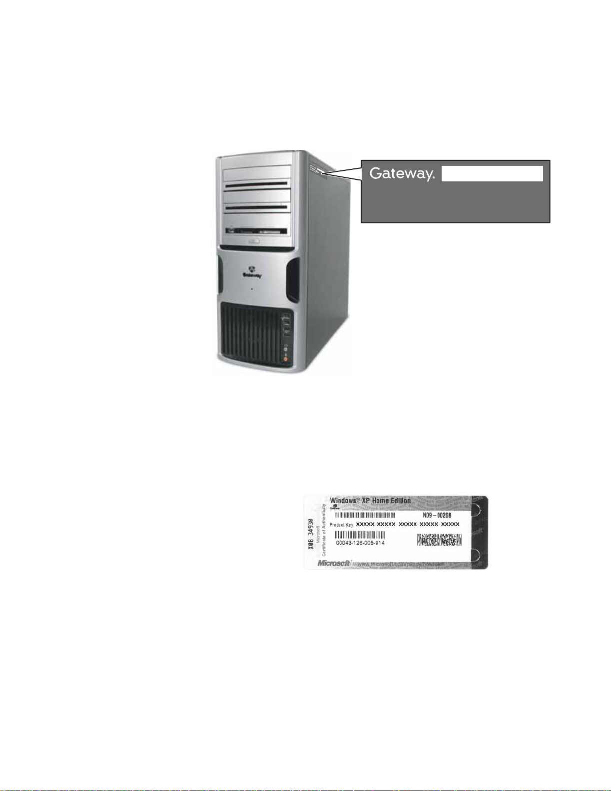
The label on the side of your computer case contains information that identifies
your computer model and serial number. Gateway Customer Care will need this
information if you call for assistance.
Gateway contact information
Web
site:
ga
tew
ay.com
9
0
0
3
7
0
2
Online Support:
Tech Support Phone:
Tech Support Hours:
Microsoft Certificate of Authenticity
The Microsoft Certificate of Authenticity label found on the back or side of your
computer includes the product key code for your operating system. If you ever
reinstall Windows from the installation CD or DVD, you will need to enter these
numbers to activate Windows.
3
Page 7

CHAPTER 1: About This Reference www.gateway.com
4
Page 8

CHAPTER 2
Hardware Basics
•Front
•Back
5
Page 9
CHAPTER 2: Hardware Basics www.gateway.com
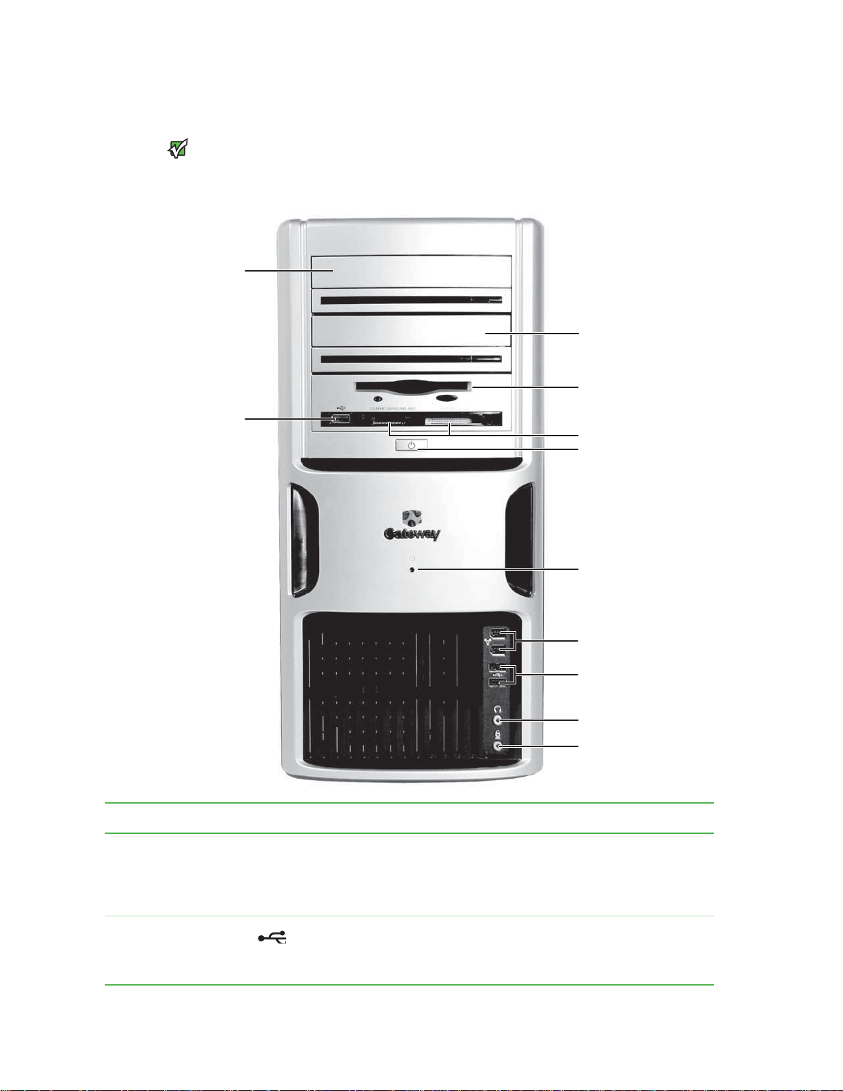
Front
Your computer hardware options and
port locations may vary from this
Important
illustration.
DVD/CD drive
USB port
(optional)
DVD/CD drive
(optional)
Diskette drive
(optional)
Memory card reader
(optional)
Power button
Hard drive activity
indicator
IEEE 1394 ports
(optional)
USB port
(optional)
Headphone jack
Microphone jack
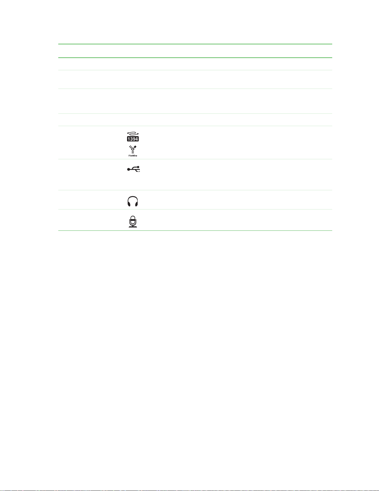
Component Icon Description
DVD/CD drive Use this drive to listen to audio CDs, install games and programs, watch DVDs, and store large
files onto recordable discs (depending on drive type). This drive may be a CD, recordable CD,
DVD, or recordable DVD drive. To identify your drive type and for more information about your
drive, see the User Guide, which is available on your hard drive. To access this guide, click
Start, All Programs, then click Gateway Documentation.
USB port (optional) Plug a USB (Universal Serial Bus) device (such as a USB Iomega™ Zip™ drive, printer, scanner,
camera, keyboard, or mouse) into one of these ports. For more information, see your User
Guide, which is available on your hard drive. To access this guide, click
then click
Gateway Documentation.
Start, All Programs,
6
Page 10
www.gateway.com
Component Icon Description
Diskette drive (optional) Insert a standard 3.5-inch diskette into the diskette drive.
Front
Memory card reader
(optional)
Power button Press this button to turn the power on or off. You can also configure the power button to
Hard drive activity indicator Lights when the hard drive is active.
IEEE 1394 ports (optional) Plug IEEE 1394 (also known as Firewire
USB ports (optional) Plug a USB (Universal Serial Bus) device (such as a USB Iomega™ Zip™ drive, printer, scanner,
Headphone jack Plug powered, analog front speakers, an external amplifier, or headphones into this jack. This
Microphone jack Plug a microphone into this jack. This jack is color-coded red or pink.
Insert a memory card from a digital camera, MP3 player, PDA, cellular telephone, or other
devices into the memory card reader.
operate in Standby/Resume mode or Hibernate mode. The power indicator lights when the
computer is turned on.
®
or i.Link®) devices (such as a digital camcorder) into
these 6-pin IEEE 1394 ports. For more information, see your User Guide, which is available on
your hard drive. To access this guide, click
Documentation
camera, keyboard, or mouse) into one of these ports. For more information, see your User
Guide, which is available on your hard drive. To access this guide, click
then click
jack is color-coded green.
Gateway Documentation.
.
Start, All Programs, then click Gateway
Start, All Programs,
7
Page 11
CHAPTER 2: Hardware Basics www.gateway.com
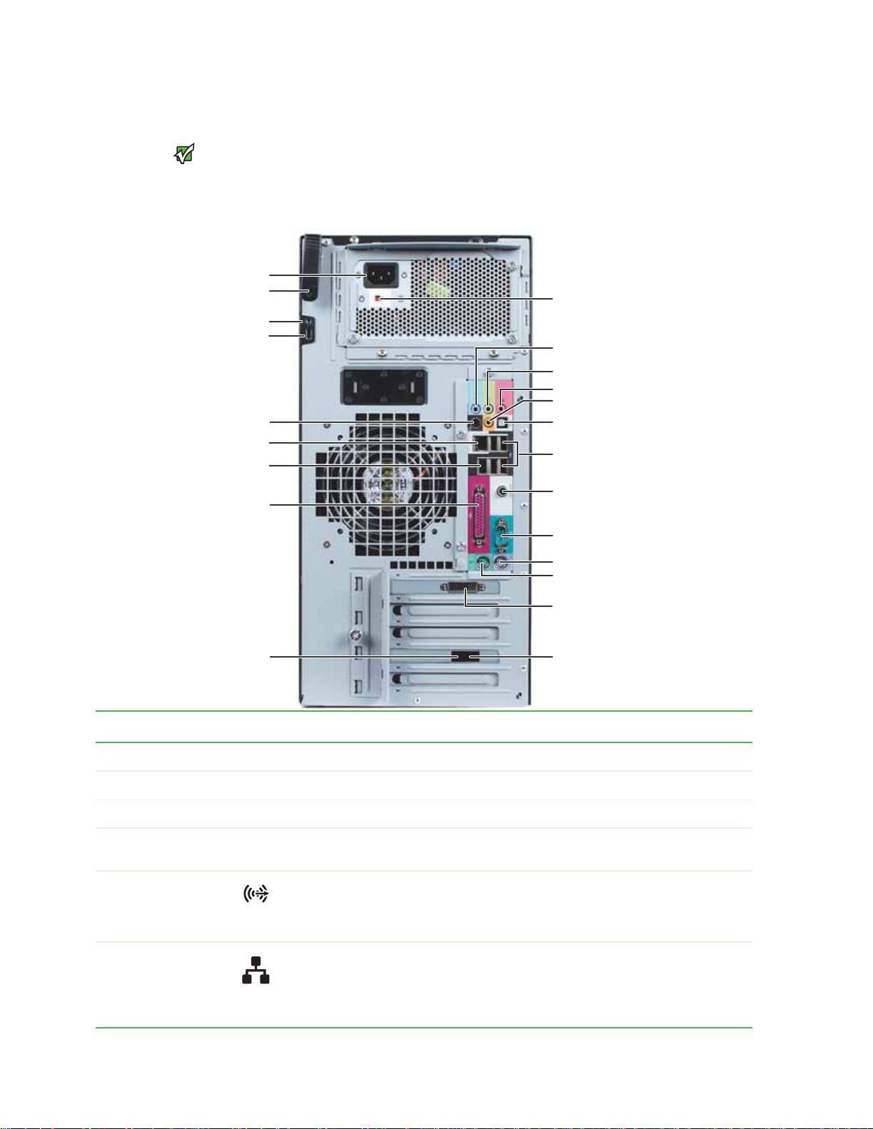
Back
Your computer hardware options and
port locations may vary from this
Rear speaker jack (optional)
Important
illustration.
Power connector
Cover release lever
Case cover thumbscrew
Kensington lock slot
Ethernet (network) jack
IEEE 1394/FireWire™/
i.Link™ port (optional)
Parallel port (optional)
Your computer includes the following components.
Voltage switch (typical)
Audio in/side speaker jack
Headphone/front speaker jack
Microphone jack
Center/subwoofer jack (optional)
S/PDIF (optical) jack (optional)
USB ports
Digital coaxial audio jack (some models)
Video port (not shown)(some models).
Serial port
PS/2 keyboard port
PS/2 mouse port
DVI monitor port
(add-in video card)
Telephone jack (optional)
Modem jack (optional)
Component Icon Description
Power connector Plug the power cord into this connector.
Cover release lever Lift this lever to open the computer cover
Case cover thumbscrew Remove this screw before opening the case.
Kensington lock slot Attach a cable lock to this slot, then attach the cable to a solid object like a desk or table to prevent
Rear speaker jack
(black plug)
Ethernet (network) jack Plug an Ethernet network cable or a device (such as a DSL or cable modem for a broadband Internet
your computer from being stolen.
Plug your rear right and left speakers into this jack.
For more information, see “Configuring the audio jacks” in your User Guide, which is available on your
hard drive. To access this guide, click
Documentation
connection) into this jack.
For more information, see “Learning about the Internet” in your User Guide, which is available on your
hard drive. To access this guide, click
Documentation
.
.
Start, All Programs, then click Gateway
Start, All Programs, then click Gateway
8
Page 12

www.gateway.com
Component Icon Description
Back
IEEE 1394 port (optional) Plug IEEE 1394 (also known as Firewire® or i.Link®) devices (such as a digital camcorder) into this 6-pin
Parallel port (optional) Plug a parallel device (such as a printer) into this port.
Telephone jack (optional) Plug the cord from your telephone into this jack.
Voltage switch Before turning on your computer, make sure that this switch is in the correct position for the correct
Audio input (Line in) jack
(blue plug)
-ORSide speaker jack
IEEE 1394 port. For more information, see your User Guide, which is available on your hard drive. To
access this guide, click
power available. The switch is preset at the factory with the correct voltage for your area.
In the United States, the utility power is supplied at a nominal 115 volts at 60 Hz. The power supply
should always be set to this when your computer is operating in the United States. In other areas of
the world, such as Europe, the utility power is supplied at 230 volts at 50 Hz. If your computer is
operating in an environment such as this, the voltage switch should be moved to 230. This switch may
not be present on your computer if it came with a non-switchable power supply.
If the back of your computer has five audio jacks, this jack is user configurable for one of the following:
Stereo in: Plug an external audio input source (such as a stereo) into this jack so you can record sound
on your computer (Default).
Stereo out: Plug your side left and right speakers into this jack.
For more information, see “Configuring the audio jacks” in your User Guide, which is available on your
hard drive. To access this guide, click
Documentation.
If the back of your computer has three audio jacks, this jack is the audio input (line in) jack. Plug an
external audio input source (such as a stereo) into this jack so you can record sound on your computer.
Start, All Programs, then click Gateway Documentation.
Start, All Programs, then click Gateway
Headphone/analog
speakers jack (green
plug)
-ORFront speakers jack
Microphone jack (pink
plug)
Center/subwoofer jack
(orange plug)(optional)
S/PDIF output jack
(optional)
USB ports Plug USB (Universal Serial Bus) devices (such as a USB Iomega™ Zip™ drive, printer, scanner, camera,
Digital coaxial audio por t
(some models)
-ORVideo port
If the back of your computer has five audio jacks, this jack is user configurable for one of the following:
Headphone: Plug headphones or amplified speakers into this jack (Default).
Stereo out: Plug your front left and right speakers into this jack.
For more information, see “Configuring the audio jacks” in your User Guide, which is available on your
hard drive. To access this guide, click
Documentation
If the back of your computer has three audio jacks, this jack is the headphone/analog speaker (line out)
jack. Plug powered speakers, an external amplifier, or headphones into this jack.
Plug a microphone into this jack.
Plug your center speaker and subwoofer into this jack.
For more information, see “Configuring the audio jacks” in your User Guide, which is available on your
hard drive. To access this guide, click
Documentation
Plug an optical cable from an amplifier or entertainment system into this jack for digital sound.
keyboard, or mouse) into these ports. For more information, see your User Guide, which is available
on your hard drive. To access this guide, click
Documentation
Plug a single digital coaxial a udio connector into this jack for digital audio. Provides digital audio output
from a CD or DVD (optional).
Plug a monitor into this port (optional).
.
.
.
Start, All Programs, then click Gateway
Start, All Programs, then click Gateway
Start, All Programs, then click Gateway
9
Page 13

CHAPTER 2: Hardware Basics www.gateway.com
Component Icon Description
Serial por t Plug a serial device into this por t. For more information, see your User Guide, which is available on your
PS/2 keyboard port Plug a Personal System/2
PS/2 mouse port Plug a PS/2 mouse into this port.
DVI monitor port
(optional)
Modem jack (optional) Plug a modem cable into this jack. For more information, see your User Guide, which is available on
hard drive. To access this guide, click Start, All Programs, then click Gateway
Documentation
Plug a digital monitor into this port.
your hard drive. To access this guide, click
Documentation
.
®
(PS/2) keyboard into this port.
.
Start, All Programs, then click Gateway
10
Page 14

CHAPTER 3
Maintenance Basics
• Preventing static electricity discharge
• Opening the case
• Closing the case
• Adding or replacing memory
• Replacing the system battery
• Adding or replacing a CD or DVD drive
• Adding or replacing an optional diskette drive
• Adding or replacing the memory card reader
• Adding or replacing a hard drive
• Replacing the front fan
• Replacing the rear fan
• Replacing the power supply
• Replacing the heat sink and processor
• Replacing the I/O board
• Adding or replacing an expansion card
• Replacing the system board
11
Page 15

CHAPTER 3: Maintenance Basics www.gateway.com
Preventing static electricity discharge
To avoid exposure to dangerous
electrical voltages and moving parts,
turn off your computer and unplug the
power cord and modem and network
cables before opening the case.
To prevent risk of electric shock, do not
insert any object in to the vent holes of the
ESD can permanently damage
electrostatic discharge-sensitive
components in your computer. Prevent
ESD damage by following ESD guidelines
every time you open the computer case.
Warning
Wa rning
power supply.
Caution
The components inside your computer are extremely sensitive to static
electricity, also known as electrostatic discharge (ESD).
Before opening the computer case, follow these guidelines:
■ Wear a grounding wrist strap (available at most electronics stores) and
attach it to a bare metal part of your computer.
■ Turn off your computer.
■ Touch a bare metal surface on the back of the computer.
■ Unplug the power cord and the modem and network cables.
Before working with computer components, follow these guidelines:
■ Avoid static-causing surfaces such as carpeted floors, plastic, and packing
foam.
■ Remove components from their antistatic bags only when you are ready
to use them. Do not lay components on the outside of antistatic bags
because only the inside of the bags provide electrostatic protection.
■ Always hold expansion cards by their edges or their metal mounting
brackets. Avoid touching the edge connectors and components on the
cards. Never slide expansion cards or components over any surface.
Opening the case
Removing the side panel
To avoid exposure to dangerous
electrical voltages and moving parts,
turn off your computer, then unplug the
power cord and modem cable before
Wa rning
opening the case.
Your computer case provides easy access to internal components.
To remove the side panel:
1 Follow the instructions in “Preventing static electricity discharge” on
page 12.
2 Shut down your computer, then disconnect the power cord and modem,
network, and all peripheral device cables.
3 Press the power button for ten seconds to drain any residual power from
your computer.
4 Remove the thumbscrew on the side panel cover. For the location of the
thumbscrew, see “Back” on page 8.
12
Page 16

www.gateway.com
Opening the case
Your computer hardware options and
port locations may vary from these
Important
illustrations.
5 Lift the cover release lever.
6 Swing the side panel away from the computer, then lift the panel away
from the computer.
13
Page 17

CHAPTER 3: Maintenance Basics www.gateway.com
Removing the front bezel
To remove the front bezel:
■ Push on the three spring tabs, grasp the right side of the front bezel, then
pull the bezel out and away from the case.
Closing the case
Replacing the front bezel
To replace the front bezel:
1 Insert the tabs on the left side of the bezel into the slots in the left side
of the computer.
2 Swing the right side of the bezel in so the tabs on the right side of the
bezel go into the slots on the right side of the computer.
3 Press the right side of the bezel firmly until it snaps into place.
14
Page 18

www.gateway.com
Replacing the side panel
Adding or replacing memory
To replace the side panel:
1 Make sure that all of the internal cables are arranged inside the computer
so they will not be pinched when you close the computer.
Your computer hardware options and
Important
port locations may vary from this
illustration.
2 Insert the bottom edge of the side panel into the inside bottom edge of
the computer, then swing the side panel in toward the top of the
computer to secure it into place.
3 Replace the side panel thumbscrew.
4 Reconnect the cables and power cord.
Adding or replacing memory
When you upgrade the computer memory, make sure that you install the
correct type of memory module for your computer. Your computer uses DIMM
memory.
To install or replace DIMM memory:
1 Remove the side panel by following the instructions in “Removing the side
panel” on page 12.
2 For more stability, place your computer on its side. To avoid scratching the
case, place it on a towel or other non-abrasive surface.
15
Page 19

CHAPTER 3: Maintenance Basics www.gateway.com
3 Find the memory module banks on your system board.
4 If you are removing a DIMM from the memory module bank, gently pull
the plastic tabs away from the sides of the memory module and remove it.
- OR -
If you are adding a DIMM to an empty memory module bank, gently pull
the plastic tabs away from the sides of the memory module bank.
5 Align the notches on the new DIMM with the notches on the memory
module bank and press the module firmly into the bank. The tabs on the
sides of the memory module should secure the memory module
automatically. When the module is secure, you hear a click.
6 Return your computer to its upright position.
7 Replace the side panel by following the instructions in “Replacing the side
panel” on page 15.
8 Reconnect the cables and the power cord.
9 Turn on your computer. Windows starts and the Windows desktop
appears.
10 Click Start, Control Panel, then click Performance and Maintenance (if
in Category view). Click/Double-click System. The amount of memory in
your computer is shown at the bottom of the System Properties dialog box
in the General tab.
16
Page 20

www.gateway.com
Replacing the system battery
Replacing the system battery
Danger of explosion if battery is
Replace only with the same or equivalent
type recommended by the manufacturer.
Dispose of used batteries according to
local hazardous materials regulations.
Your computer’s battery location may
vary from the illustration below.
Warning
incorrectly replaced.
Important
If the computer clock does not keep time or the settings in the BIOS Setup utility
are not saved when you turn off your computer, replace the system battery. Use
a battery of the same size and voltage as the original battery that was in your
computer.
To replace the battery:
1 Restart your computer.
2 During the restart, press and hold the F1 key. The main menu of the
BIOS Setup utility opens.
3 Write down all the values in the menus and submenus, then exit from the
utility.
4 Shut down your computer.
5 Remove the side panel by following the instructions in “Removing the side
panel” on page 12.
6 For more stability, place your computer on its side. To avoid scratching the
case, place it on a towel or other non-abrasive surface.
7 Locate the old battery on the system board and note its orientation. You
will need to install the new battery the same way.
8 Push the battery release tab. The battery pops out of the socket.
Battery
9 Make sure that the positive (+) side of the new battery is facing up, then
Battery release tab
press the battery into the socket until it snaps into place.
10 Return your computer to its upright position.
11 Replace the side panel by following the instructions in “Replacing the side
panel” on page 15.
12 Reconnect all external cables and the power cord.
13 Turn on your computer.
14 Open the BIOS Setup utility.
17
Page 21

CHAPTER 3: Maintenance Basics www.gateway.com
15 In the BIOS Setup utility, restore any settings that you wrote down in
Step 3.
16 Save all your settings and exit the BIOS Setup utility.
Adding or replacing a CD or DVD drive
To add or replace a CD or DVD drive:
1 Remove the side panel by following the instructions in “Removing the side
panel” on page 12.
2 Remove the front bezel by following the instructions in “Removing the
front bezel” on page 14.
The color and shape of your replacement
drive's front cover may vary from your
Important
original drive.
3 If you are installing a new drive, go to Step 7.
- OR -
If you are replacing an existing drive, disconnect the cables from the drive,
noting their locations and orientation. You will reconnect the cables after
you install the new drive. (CD/DVD drive shown.)
4 Remove the drive thumbscrew from the CD or DVD drive.
Drive thumbscrew
5 Slide the drive release latch toward the back of the computer to release
the drive.
18
6 Slide the drive forward and out of the drive bay.
Page 22

www.gateway.com
7 If you are replacing a drive, note any jumper settings on the old drive and
Adding or replacing an optional diskette drive
set the jumpers on the new drive to be the same. If you are installing a
new drive, follow the manufacturer’s instructions.
8 Slide the new drive into the drive bay, line up the thumbscrew hole on
the drive bay with the screw hole on the drive, then slide the drive release
latch toward the front of the computer to lock the drive into place. You
do not need to replace the thumbscrew because it was originally installed
for shipping purposes.
9 Connect the drive cables using your notes from Step 3. If you are installing
a new drive, follow the manufacturer’s instructions.
10 Replace the front bezel by following the instructions in “Replacing the
front bezel” on page 14.
11 Replace the side panel by following the instructions in “Replacing the side
panel” on page 15.
Adding or replacing an optional diskette drive
The color and shape of your replacement
Important
drive's front cover may vary from your
original drive.
To add or replace a diskette drive:
1 Remove the side panel by following the instructions in “Removing the side
panel” on page 12.
2 Remove the front bezel by following the instructions in “Removing the
front bezel” on page 14.
3 If you are installing a new drive, go to Step 7.
- OR -
If you are replacing an existing drive, disconnect the cables from the drive,
noting their locations and orientation. You will reconnect the cables after
you install the new drive.
4 Remove the thumbscrew from the diskette drive.
Thumbscrew
19
Page 23

CHAPTER 3: Maintenance Basics www.gateway.com
5 Slide the drive release latch back to unlock the drive, then slide the drive
forward and out of the drive bay.
6 Slide the new drive into the drive bay.
7 Slide the drive release latch forward to lock the drive into place. You do
not need to replace the thumbscrew because it was originally installed for
shipping purposes.
8 Reconnect the drive cables using your notes from Step 3. If you are
installing a new drive, follow the manufacturer’s instructions.
9 Replace the front bezel by following the instructions in “Replacing the
front bezel” on page 14.
10 Replace the side panel by following the instructions in “Replacing the side
panel” on page 15.
Adding or replacing the memory card reader
To replace the memory card reader:
1 Remove the side panel by following the instructions in “Removing the side
panel” on page 12.
2 Remove the front bezel by following the instructions in “Removing the
front bezel” on page 14.
3 If you are adding a memory card reader, go to Step 7.
- OR -
If you are replacing a memory card reader, proceed to the next step.
4 Disconnect the memory card reader cables, noting their locations and
orientation. (You will reconnect the cables after you install the new
memory card reader.)
20
Page 24

www.gateway.com
Adding or replacing the memory card reader
5 Remove the thumbscrew holding the card reader in the drive bay.
Thumbscrew
6 Slide the drive release latch back to release the card reader, then slide the
card reader out of the case.
The color and shape of your replacement
Important
reader's front cover may vary from your
original reader.
7 Note any jumper settings on the old card reader and set the new card
reader jumpers the same. If you are installing a new card reader, refer to
the instructions that came with the card reader.
8 Slide the new card reader into the bay from the front of the case, then slide
the drive release latch forward to lock the drive into place. You do not
need to replace the thumbscrew because it was originally installed for
shipping purposes.
9 Connect the new card reader cables, using your notes from Step 4. If you
are adding a new card reader, refer to the instructions that came with the
card reader.
10 Replace the bezel by following the instructions in “Replacing the front
bezel” on page 14.
11 Replace the computer case’s side panel by following the instructions in
“Replacing the side panel” on page 15.
21
Page 25

CHAPTER 3: Maintenance Basics www.gateway.com
Adding or replacing a hard drive
Before replacing the hard drive in your
computer, you must create restore discs
and print a copy of the restore chapter in
the User Guide. If this is not done, you will
not be able to reinstall your drivers and
Caution
programs.
To add or replace a hard drive:
1 Create restore discs and print the restore chapter in the User Guide. To
access the User Guide, click Start, All Programs, then click Gateway
Documentation.
2 Remove the side panel by following the instructions in “Removing the side
panel” on page 12.
3 If you are adding a new drive, go to Step 7.
- OR -
If you are replacing an existing drive, go to the next step.
4 Disconnect the drive cables, noting their locations and orientation. (You
will reconnect the cables after you install the new drive.)
5 Slide the drive release latch in the direction shown.
22
6 Remove the hard drive by sliding it out of the drive bay.
Page 26

www.gateway.com
Replacing the front fan
7 Note any jumper settings on the old drive and set the jumper on the new
drive to be the same. If you are installing a new drive, follow the
manufacturer’s instructions.
Jumper
8 Slide the new drive into the drive bay, then secure it in the drive bay by
sliding the drive release latch in toward the computer.
9 If you are replacing a drive, reconnect the drive cables using your notes
from Step 4. If you are installing a new drive, follow the manufacturer’s
instructions.
10 Replace the side panel by following the instructions in “Replacing the side
panel” on page 15.
11 Reconnect all external cables and the power cord.
12 Turn on your computer.
13 If you installed a new drive, format and partition the drive according to
the manufacturer’s instructions (available on the manufacturer’s Website).
14 If Windows does not start, install Windows using the operating system CD
that came with your computer, then install the drivers and applications
using the drivers and applications disc that you created. Follow the
instructions in the restore chapter of the User Guide that you printed to
reinstall the drivers and programs.
Replacing the front fan
To replace the front fan:
1 Remove the side panel by following the instructions in “Removing the side
panel” on page 12.
23
Page 27

CHAPTER 3: Maintenance Basics www.gateway.com
2 Remove the fan cover by squeezing the top and bottom, then pulling it
out.
1
2
1
3 Disconnect the fan cable from the system board. The location of the fan
connection may vary, so trace the fan cable from the fan to the system
board.
24
4 Remove the fan mount by pressing in on the flat area near the front, then
rotating the fan mount back.
2
1
5 Slide the old fan out of the fan mount.
6 Slide the new fan into the fan mount.
Page 28

www.gateway.com
Replacing the rear fan
Be careful not to catch the wires
connecting the power button to the
system board when rotating the fan
mount. A notch has been provided for
Caution
routing these wires.
7 Insert the tabs on the rear of the fan mount into the slots provided, then
8 Reconnect the fan cable to the system board.
9 Replace the fan cover.
10 Replace the side panel by following the instructions in “Replacing the side
Replacing the rear fan
You need a Phillips screwdriver to replace
Tips & Tricks
the rear fan.
1 Remove the side panel by following the instructions in “Removing the side
2 Disconnect the fan cable from the system board. The location of the fan
rotate the mount into place. The mount should lock into place.
panel” on page 15.
To replace the rear fan:
panel” on page 12.
connection may vary, so trace the fan cable from the fan to the system
board.
25
Page 29

CHAPTER 3: Maintenance Basics www.gateway.com
Your computer hardware options and
port locations may vary from this
Important
illustration.
3 Remove the four screws that secure the fan to the inside back of the
computer, then remove the fan from inside the computer. Note the
orientation of the fan (which way it blows) and install the new fan the same
way.
Screws
4 Insert the new fan into the computer and line it up with the screw holes
on the back of the computer, then replace the screws that secure it to the
back of the computer.
5 Reconnect the fan cable to the system board.
6 Replace the side panel by following the instructions in “Replacing the side
panel” on page 15.
7 Reconnect all external cables and the power cord.
8 Turn on your computer.
Replacing the power supply
You need a Phillips screwdriver to replace
Tips & Tricks
To replace the power supply:
the power supply.
1 Remove the side panel by following the instructions in “Removing the side
panel” on page 12.
2 Disconnect the power supply cables from all components (such as hard
drives, CD or DVD drives, and the system board), noting their locations and
orientation. (You will reconnect the cables after you install the new power
supply.)
26
Page 30

www.gateway.com
Replacing the heat sink and processor
Your computer hardware options and
port locations may vary from this
Important
illustration.
3 Remove the three screws that secure the power supply to the computer.
Screws
4 Slide the power supply away from the back of the computer, then lift up.
5 Install the new power supply into the case, then install the three screws
to secure the power supply to the case.
6 Reconnect the power supply cables using your notes from Step 2.
7 Replace the side panel by following the instructions in “Replacing the side
panel” on page 15.
Replacing the heat sink and processor
You need a Phillips screwdriver to replace
Tips & Tricks
To replace the heat sink and processor:
the heat sink.
1 Remove the side panel by following the instructions in “Removing the side
panel” on page 12.
2 For more stability, place your computer on its side. To avoid scratching the
case, place it on a towel or other non-abrasive surface.
27
Page 31

CHAPTER 3: Maintenance Basics www.gateway.com
3 Remove the fan cover by squeezing the top and bottom, then pulling it
out.
1
2
1
4 Loosen the four screws that secure the heat sink to the system board, then
remove the heat sink.
The heat sink has Thermal Interface
Material (TIM) located on the bottom of
it. Use caution when you remove the old
heat sink or unpack the new heat sink so
you do not damage the TIM.
Caution
Screws
5 Release the processor by pushing down on the lever and then lifting the
lever completely up.
28
6 Remove the processor from the system board.
7 Install the new processor onto the system board making sure that Pin 1
on the processor (indicated by the silk-screened arrow on the corner of
the processor) aligns with Pin 1 on the processor socket (indicated by the
absence of a pin hole in the processor socket), then return the lever to its
locked position.
Page 32

www.gateway.com
8 Place the heat sink on the system board, then tighten the screws that
secure it to the system board.
9 Replace the fan cover.
10 Return your computer to its upright position.
11 Replace the side panel by following the instructions in “Replacing the side
panel” on page 15.
Replacing the I/O board
Replacing the I/O board
You need a Phillips screwdriver to replace
Tips & Tricks
the I/O board.
To replace the front I/O board:
1 Remove the side panel by following the instructions in “Removing the side
panel” on page 12.
2 Remove the front bezel by following the instructions in “Removing the
front bezel” on page 14.
3 Remove the screw that secures the front I/O assembly to the computer,
then remove the I/O assembly.
Screw
29
Page 33

CHAPTER 3: Maintenance Basics www.gateway.com
4 Remove the screw that secures the front I/O panel board to the computer,
then remove the I/O panel board by pushing it toward the back of the
computer.
Screw
5 Disconnect the cable from the old I/O panel board and connect it to the
new I/O panel board.
6 Insert the new I/O panel board into the computer, then replace the screw.
7 Place the front I/O assembly onto the computer, then replace the screw.
8 Replace the front bezel by following the instructions in “Replacing the
front bezel” on page 14.
9 Replace the side panel by following the instructions in “Replacing the side
panel” on page 15.
30
Page 34

www.gateway.com
Adding or replacing an expansion card
To add or replace an expansion card:
1 Remove the side panel by following the instructions in “Removing the side
panel” on page 12.
Adding or replacing an expansion card
Your computer hardware options and
port locations may vary from this
Important
illustration.
2 Remove the thumbscrew from the expansion card cover.
Expansion card
cover
Thumb screw
3 For more stability, place your computer on its side. To avoid scratching the
case, place it on a towel or other non-abrasive surface.
4 If you are replacing a card, disconnect any cables that are attached to the
card, noting their locations and orientation. (You may have to reconnect
the cables after you install the new card.)
5 Remove the old expansion card (if necessary). You can slightly seesaw the
card end-to-end to loosen it, but do not bend the card sideways.
31
Page 35

CHAPTER 3: Maintenance Basics www.gateway.com
Do not touch the contacts on the bottom
part of the expansion card. Touching the
contacts can cause electrostatic damage
Caution
to the card.
6 Install the new card into the expansion slot. You can slightly seesaw the
card end-to-end to help insert the card, but do not bend the card
sideways.
7 Replace the thumbscrew in the expansion card cover.
8 Reconnect the expansion card cables (if any) using your notes from Step 4,
or, if adding a new card, follow the manufacturers instructions.
9 Return your computer to its upright position.
10 Replace the side panel by following the instructions in “Replacing the side
panel” on page 15.
Replacing the system board
To replace the system board:
You need a Phillips screwdriver to replace
Tips & Tricks
the system board.
1 Remove the side panel by following the instructions in “Removing the side
panel” on page 12.
2 For more stability, place your computer on its side. To avoid scratching the
case, place it on a towel or other non-abrasive surface.
3 Disconnect any cables that are attached to any expansion cards, noting
their locations and orientation. (You will reconnect the cables after you
install the cards on the new board.)
4 Remove the expansion cards by following the instructions in “Adding or
replacing an expansion card” on page 31. You can slightly seesaw a card
end-to-end to loosen it, but do not bend a card sideways.
32
Page 36

www.gateway.com
Replacing the system board
5 Remove the fan cover by squeezing the top and bottom, then pulling it
out.
1
2
1
6 Find the memory module banks on your system board.
The heat sink has Thermal Interface
Material (TIM) located on the bottom of
it. Use caution when you remove the old
heat sink or unpack the new heat sink so
you do not damage the TIM.
Caution
7 Gently pull the plastic tabs away from the sides of the memory modules,
then remove them.
8 Loosen the four screws that secure the heat sink to the system board, then
remove the heat sink.
Screws
9 Disconnect the power and data cables from the system board, noting their
locations and orientation. (You will reconnect the cables after you install
the new board.)
33
Page 37

CHAPTER 3: Maintenance Basics www.gateway.com
10 Remove the seven system board screws.
Screws
Screws
11 Lift the system board up and out of the case.
12 Align the new system board on the standoffs and secure it into the
computer case with the screws.
13 If your replacement system board does not include a processor, go to
Step 14.
-OR-
If your replacement system board includes a processor, go to Step 17.
14 Release the processor from the old system board by pushing down on the
lever and then lifting the lever completely up.
34
15 Remove the processor from the old system board.
16 Install the processor onto the new system board making sure that Pin 1
on the processor (indicated by the silk-screened arrow on the corner of
the processor) aligns with Pin 1 on the processor socket (indicated by the
absence of a pin hole in the processor socket), then return the lever to its
locked position.
17 Connect the power and data cables using your notes from Step 9.
Page 38

www.gateway.com
Replacing the system board
18 Place the heat sink over the processor, then tighten the screws that secure
it to the system board.
19 Align the notches on the memory modules with the notches on the
memory module banks and press the modules firmly into the banks. The
tabs on the sides of the memory modules should secure the memory
modules automatically. When a module is secure, you hear a click.
Do not touch the contacts on the bottom
part of the expansion card. Touching the
contacts can cause electrostatic damage
Caution
to the card.
20 Install the expansion cards into the expansion slots. You can slightly
seesaw a card end-to-end to help insert the card, but do not bend the card
sideways.
21 Reconnect the expansion card cables using your notes from Step 3.
22 Install the fan cover.
23 Return your computer to its upright position.
24 Replace the side panel by following the instructions in “Replacing the side
panel” on page 15.
35
Page 39

CHAPTER 3: Maintenance Basics www.gateway.com
36
Page 40

APPENDIX A
Safety, Regulatory, and Legal Information
• Important safety information
• Regulatory compliance statements
• Environmental information
•Notices
37
Page 41

APPENDIX A: Safety, Regulatory, and Legal Information www.gateway.com
Important safety information
Your Gateway system is designed and tested to meet the latest standards for safety of information technology equipment. However, to
ensure safe use of this product, it is i mportant that the safety instructions marked on the product and in the documentation are followed.
Warning
Always follow these instructions to help
guard against personal injury and
damage to your Gateway system.
Setting up your system
■
Read and follow all instructions marked on the product and in the documentation before you operate your system. Retain all safety and
operating instruc tions for future use.
■
Do not use this product near water or a heat source such as a radiator.
■
Set up the system on a stable work surface.
■
The product should be operated only from the type of power source indicated on the rating label.
■
If your computer has a voltage selector switch, make sure that the switch is in the proper positio n for your area. The voltage selector
switch is set at the factor y to the correct voltage.
■
Openings in the computer case are provided for ventilation. Do not block or cover these openings. Make sure you provide adequate space,
at least 6 inches (15 cm), around the system for ventilation when you set up your work area. Never insert objects of any kind into the
computer ventilation openings.
■
Some products are equipped with a three -wire power cord to make sure that the product is properly grounded when in use. The plug on
this cord will fit only into a grounding-type outlet. This is a safety feature. If you are unable to insert the plug into an outlet, contact an
electrician to install the ap propriate outlet.
■
If you use an extension cord with this system, m ake sure that the total ampere rating on the products plugged into the extension cord
does not exceed the extension cord ampere rating.
■
If your system is fitted with a TV Tuner, cable, or satellite receiver card, make sure that the antenna or cable system is electrically
grounded to provide some protection against voltage surges and buildup of static charges.
Do not use Gateway products in areas
Warning
classified as hazardous locations. Such
areas include patient care areas of
medical and dental facilities,
oxygen-laden environments, or
industrial facilities.
Warning
To reduce the risk of fire, use only
No. 26 AWG or larger
telecommunications line cord.
Care during use
■
Do not walk on the power cord or all ow anything to rest on it.
■
Do not spill anything on the system. The best way to avoid spills is to avoid eating and drinking near your system.
■
Some products have a replaceable CMOS battery on the system board. There is a danger of explosion if the CMOS battery is replaced
incorrectly. Replace the battery with the same or equivalent type recommended by the manufacturer. Dispose of b atteries according to
the manufacturer’s instructions.
■
When the computer is turned off, a small a mount of electrical current still flow s through the computer. To avoid electrical s hock, always
unplug all power cables and modem cables from the wall outlets before cleaning the system.
■
Unplug the system from the wall outlet and refer serv icing to qualified personnel if :
■
The power cord or pl ug is damaged.
■
Liquid has been spi lled into the system.
■
The system does not operate properly when the operating instructions are followed.
■
The system was d ropped or the cabi net is damaged.
■
The system performance changes.
Replacement parts and accessories
Use only replacement parts a nd accessories recommended by Gateway.
38
Page 42

www.gateway.com
Regulatory compliance statements
United States of America
Federal Communications Commission (FCC) Unintentional emitter per FCC Part 15
This device has been tested and found to comply with the lim its for a Class B digital device, pursuant to Part 15 of the FCC rules. These limits
are designed to provide reasonable p rotection against harmful interf erence in a residential installation. This equipment generates, uses,
and can radiate radio frequency energy and, if not installed and used in accordance with the instructions, may cause harmful inter ference to
radio or television reception . However, the re is no guarantee that interference wil l not occur in a partic ular installation. If this equipment
does cause interference to radio and tel evision reception, which can be determined by turning the equ ipment off and on, the user is
encouraged to try to correct the interference by one or more of the following meas ures:
■
Reorient or rel ocate the receiving antenn a
■
Increase the separation between the equipment and receiver
■
Connect the equipment to an outlet on a different circuit from that to which the receiver is connected
■
Consult the dealer or an experienced radio/TV technician for help.
Compliance Accessor ies: The accessories associated with this equipment are: shielded video cable when an external m onitor is
connected. These accessories are required to be used in order to ensure compliance with FCC rules.
FCC declaration of conformity
Responsible party:
Gateway Companies, Inc.
610 Gateway Drive, North Sioux City, SD 57049
(605) 232-2000Fax: (605) 232-2023
Product:
Gateway BTX Tower
This device complies with Part 1 5 of the FCC Rules. Operation of this product is subject to the following t wo conditions: (1) this device may
not cause harmful interference, and (2) this device mu st accept any interference received, including interference that may cause undesired
operation.
Changes or modifications not expressly
approved by Gateway could void the FCC
compliance and negate your authority to
This product contains chemicals,
including lead, known to the State of
California to cause cancer, birth defects
or reproductive harm.
Caution
operate the product.
Warning
California Proposition 65 Warning
Telecommunications per Part 68 of the Code of Federal Regulations (CFR 47)
(applicable to products fitted with USA modems)
Your modem complies with Part 68 of the Code of Federal Regulations (CFR 47) rules. On the computer or modem card is a label that
contains the FCC registration number and Ringer Equivalence Number (REN) for this device. If requested, this information must be provided
to the te lephone company.
A telephone line cord with a modular plug is requi red for use with this device. Th e modem
is designed to be connected to the telephone network or premises wiring using a
compatible modular jack which is Part 68-compliant. See installation inst ructions for
details.
The Ringer Equivalence Number (REN) is used to determine the number of devices which may be connected to the telephone line. Excessive
RENs on a telephone l ine may result in the devices not ringin g in response to an incoming call. In most areas, the sum of RENs should not
exceed five (5.0). To be certain of the number of devices that may be connected to a line, as determined by the total RENs, contact the local
teleph one compa ny.
If this device causes harm to the telephone ne twork, the telephone company will notify you in advance that temporar y discontinuance of
service may be required. The telephone company may request that you disconnec t the equipment until the problem is resolved.
The telephone company may make changes in its faci lities, equipment, operations, or procedures that could affect the operation of this
equipment. If this happens, the telephone company will provide advance notice in order for you to make necessary modifications to
maintain uninterrupted service.
This equipment cannot be u sed on telephone company-provided coin ser vice. Connection to part y line service is subjec t to state tariffs.
Contact the state public uti lity commission or public se rvice commission for info rmation.
When programming or making test calls to emergency numbers:
■
Remain on the line and briefly explain to the dispatcher the reason for the call.
■
Perform such activities in the off-peak hours such as early morning o r late evenings.
39
Page 43

APPENDIX A: Safety, Regulatory, and Legal Information www.gateway.com
The United States Telephone Consumer Protection Act of 1991 makes it unlawful for any person to use a com puter or other electronic device
to send any message via a telephone fax machine unless such message clearly contains, in a margin at the top or bottom of each
transmitted page or on the first page o f the transmission, the date and time it is sent, an identification o f the business, other entity, or other
individual sending the message, and the telephone number of the sending machine or such business, other entity, or individual. Refer to
your fax communication software documentation for details on how to comply with the fax-branding requirement.
Canada
Industry Canada (IC) Unintentional emitter per ICES-003
This digital apparatus does not exceed the Class B limits for radio noise emissions f rom digital apparatus as set out in the radio interferen ce
regulations of Industr y Canada.
Le présent appareil numérique n’émet pas de bruits radioélectriques dépassant les limites applicables aux appareils numériques de Classe B
prescrites dans le règlement sur le brouillage radioélectrique édicté par Industrie Canada.
Telecommunications per Industry Canada CS-03 (for products fitted with an
IC-compliant mo dem)
The Industry Canada label identifies certified equipment. This certification means that the equipment meets cer tain telecommunications
network protective, operation, and safety requirements. The Department does not guarantee the equipment will operate to the users’
satisfaction.
Before installing this e quipment, users should make sure that it is permiss ible to be connected to the facilities of the local
telecommunications company. The equipment must also be installed using an accepta ble method of connection. In some cases, the inside
wiring associated with a single -line individual service may be ex tended by means of a certified connec tor assembly. The customer should
be aware that compliance with the above co nditions may not prevent degradation of service in some situations.
Repairs to certified equipment should be made by an authorized Canadian maintenance facility designated by the supplier. Any repairs or
alterations made by the user to this equipment, or equip ment malfunctions, may give the telecommunications company cause to request
the user to disconnect the equi pment.
Users should make sure, for their own protec tion, that the electrical ground connections of the power utility, telephone lines, and internal
metallic water pipe system, if present, are connected together. This precaution m ay be particularly impor tant in rural areas.
Warning
To avoid electrical shock or equipment
malfunction do not attempt to make
electrical ground connections by
yourself. Contact the appropriate
inspection authority or an electrician, as
appropriate.
The Ringer Equivalence Number (REN) assigned to each terminal device provides an indication of the maximu m number of terminals
allowed to be connected to a telephone interface. The termination on an i nterface may consist of any combination of devices subject only to
the requirement that the sum of the Ringer Equivalence Numbers of all the devices does not exceed 5.
Laser safety statement
Use of controls or adjustments or
performance of procedures other than
those specified in this manual may result
in hazardous radiation exposure. To
prevent exposure to laser beams, do not
try to open the enclosure of a CD or DVD
Warning
40
drive.
All Gateway systems equipped with CD and DVD drives comply with the appropriate safety standards, including IEC 825. The laser devices in
these components are classified as “Class 1 Laser Products” under a US Depar tment of Health and Human Services (DHHS) Radiation
Performance Standard. Should the unit ever need ser vicing, contact an authorized s ervice location.
Page 44

www.gateway.com
Environmental information
The product you have purchased contains extracted natural resources that have been used in the manufacturing process. This product may
contain substances known to be hazardous to the environment or to human health.
To prevent releases of harmful substances into the environment and to maximize the use of our natural resources, Gateway provides the
following information on how you can responsibly recycle or reuse most of the materials in you r “end of life” product.
Waste Electrical and Elec tronic Equipment (commonly known as WEEE) shou ld never be disposed of in the
municipal waste stream (residential garbage collec tion). The “Crossed-Out Waste Bin” label affixed to this product
is your reminder to d ispose of your “end of life” produc t properly.
Substances such as glass, plastics, and cer tain chemical compounds are highly recoverable, recyclable, and
reusable. You can do your part for the environment by following these simpl e steps:
■
When your electrical or elec tronic equipment is no longer useful to you, “ta ke it back” to your loca l or regional
waste collection administration for recycling.
■
In some cases, your “end of life” product may be “traded in” for credit towards the purchase of new Gateway
equipment. Call Gateway to see if this program is available in your area.
■
If you need fur ther assistance in rec ycling, reusing, or trading in your “end of life” product, you may contac t us at the Customer Care
number listed in your product’s user guide and we will be glad to help you with your effort.
Finally, we suggest that you practice other environmentally friendly actions by understanding and using the energy-saving features of this
product (where applicable), recycling the inner and outer packaging (including shipping containers) this product was delivered in, and by
disposing of or recycling used b atteries properly.
With your help, we can reduce the amount of natural resources needed to produce electrical and electronic equipme nt, minimize the use of
landfills for the disposal of “end of life” products, and generally improve our quality of life by ensuring that potentially hazardous
substances are not released into the environment and are disposed o f properly.
Notices
Copyright © 2006 Gateway, Inc.
All Rights Reserved
7565 Irvine Center Drive
Irvine, CA 92618-2930 USA
All Rights Reserved
This publication is protected by copyright and all rights are reserved. No part of it may be reproduced or transmitted by any means or in any
form, without prior consent in writing from Gateway.
The information in this manual has been carefully checked and is be lieved to be accurate. However, changes are made periodically. These
changes are incorporated in newer publication editions. Gateway may improve and/or change products described in this publication at any
time. Due to continuing system improvements, Gateway is not responsible for inaccurate information which may appear in this manua l. For
the latest product updates, consult the Gateway Web site at www.gateway.com
special, exemplary, incidental, or con sequential damages resulting from any defect or omission in this manual, even if advised of the
possibility of such damage s.
In the interest of continu ed produc t develop ment, Ga teway reser ves the right to make improvements in this manual and the p roducts it
describes at any time, without notices or obligation.
. In no event will Gateway be liable for direct, indirect,
Trademark Acknowledgments
Gateway and the Black-and-White Spot Design are trademarks or registered trademarks of Gateway, Inc. in the U.S. and other countries.
SpotShop, Spotshop.com, and Your:)Ware are trademarks of Gateway, Inc. Intel, Intel Inside logo, and Pentium are registered trademarks
and MMX is a trademark o f Intel Corporation. Microsoft, MS, MS-DOS, and Windows are trademarks or registered trademarks of Microsoft
Corporation. All other product names mentioned herein are used for identification purposes only, and may be the trademarks or registered
trademarks of their respective companies.
41
Page 45

APPENDIX A: Safety, Regulatory, and Legal Information www.gateway.com
42
Page 46

Index
A
AC power connector 8
accessories
safety precautions 38
audio
audio in jack 9
center speaker jack 9
front speaker jack 9
headphone jack 9
line in jack 9
line out jack 9
microphone jack 7, 9
rear speaker jack 8
S/PDIF jack 9
side speaker jack 9
subwoofer jack 9
audio in jack 9
B
battery
replacing 17
bezel
removing 14
replacing 14
broadband connection
connecting
8
C
cable modem
connecting
cards
adding expansion
replacing expansion 31
case
closing
opening 12
CD drive
adding 18
locating drive 6
replacing 18
Certificate of Authenticity 3
closing
computer case
front bezel 14
connecting
PS/2 keyboard
PS/2 mouse 10
to Ethernet network 8
to Internet 8
to network 8
connections
audio in
center speaker 9
8
31
14
14
10
9
digital camera 6, 7, 9, 10
digital coaxial audio 9
digital video camera 7, 9
Ethernet 8
external audio 9
external speakers 9
Firewire 7, 9
front speaker 9
headphone 9
i.Link 7, 9
IEEE 1394 7, 9
keyboard 6, 7, 9, 10
line in 9
line out 9
microphone 7, 9
modem 10
monitor 9
mouse 6, 7, 9, 10
network 8
parallel 9
power 8
power cord 8
printer 6, 7, 9
PS/2 keyboard 10
PS/2 mouse 10
rear speakers 8
scanner 6, 7, 9
serial 10
side speaker 9
subwoofer 9
USB 6, 7, 9
video camera 7, 9
Zip drive 6, 7, 9
D
digital audio out 9
digital camera
locating serial port
locating USB port 6, 7 , 9
digital monitor port 10
digital video camera
locating IEEE 1394 port
DIMM
See memory
diskette drive
adding
replacing 19
documentation
Using Your Computer
drives
CD
DVD 6
recordable CD 6
recordable DVD 6
19
6
10
2
7, 9
DSL modem
connecting
DVD drive
adding
locating drive 6
replacing 18
DVI monitor port 10
8
18
E
electrostatic discharge (ESD) 12
Ethernet jack 8
expansion card
adding
replacing 31
external audio jack 9
31
F
fan
replacing
Firewire port 7, 9
front bezel
removing 14
replacing 14
front I/O panel
replacing
23, 25
29
G
Gateway contact information 3
H
hard drive
adding 22
replacing 22
headphone jack 7, 9
heat sink
replacing
Hibernate mode 7
27
I
i.Link port 7, 9
IEEE 1394 port 7, 9
installing
battery
CD drive 18
diskette drive 19
DVD drive 18
expansion card 31
front bezel 14
front fan 23
front I/O panel 29
hard drive 22
heat sink 27
17
43
Page 47

Index www.gateway.com
memory 15
memory card reader 20
power supply 26
processor 27
rear fan 25
side panel 12
system battery 17
system board 32
J
jacks
See connections
K
keyboard
PS/2 port
USB port 6, 7, 9
10
L
label
Microsoft Certificate of
Authenticity
product 3
line in jack 9
line out jack 9
M
memory
adding 15
installing 15
replacing 15
memory card reader
locating
replacing 20
microphone jack 7, 9
Microsoft Certificate of
modem jack 10
monitor
port
monitor port 10
mouse
PS/2 port 10
USB port 6, 7, 9
6
Authenticity
9
N
network jack 8
O
opening
computer case
front bezel 14
optical connection 9
12
P
parallel port 9
port
monitor 10
ports
See connections
power
button
connector 8
Hibernate mode 7
Standby/Resume 7
power button 7
power supply
replacing
printer
parallel port
USB port 6, 7, 9
processor
replacing 27
PS/2 port
3
keyboard 10
mouse 10
7
26
9
U
USB port 6, 7, 9
V
video connection 10
voltage switch 9
W
Windows Product Key Code 3
Z
Zip drive port 6, 7, 9
R
RAM
See memory
recordable drive
locating 6
Resume mode 7
6
S
S/PDIF out 9
safety
general precautions
static electricity 12
3
serial port 10
setting up
safety precautions
side panel
removing
replacing 12
speaker jack 9
Standby mode 7
starting computer 7
static electricity 12
system battery
replacing
system board
replacing
12
17
32
38
38
T
turning off computer 7
turning on computer 7
44
Page 48

MAN GW BTX CONS HW REF R2 6/06
 Loading...