

Gates Radio Company BC-250GY-1 Instruction Book
INSTRUCTION
BOOK
FOR
TRANSMITTER
GATES'
a
MODEL BC-
250GY
-1
I.B.
#888
0836
001
Gates
Radio
Quincy,
Company
Illinois
Please
modulation
the
MODULATION
read
these
TRANSFORMER
instructions
transformer
in
INSTRUCTIONS
before
this
attempting
transmitter.
to
test
The modulation
type
may be of
in the
ings
whereas
may
modulation
order to
In
transmitter
the
a.c. to
half of
ating
equal.
a
primary
indicate
in reality,
transformer
properly
the
the
secondary
primary
normally,
transformer
which
windings.
that
will
An ohmmeter
the
this
is
is performing
check
circuit,
merely
winding.
winding.
then
these
employed
indicate
in this
unequal
transformer
normal
a
reading
normally.
this
transformer
apply
Check
If the
voltages
transformer
should
check
defective;
is
volts,
117
voltage
the
transmitter
resistance
wind-
the
of
the
and
60
on
is
of
cycle
each
oper-
outside
asproximately
be
Gates
Quincy,
Radio
Company
Illinois
INDEX
Page
SECTION
SECTION
SECTION
SECTION
- INTRODUCTION
I
- BC- 250GY
II
Oscillator
Intermediate
Power
Audio
Amplifier
Chassis
Relays
8008
Rectifier
Transformers
Wiring
Detail
Connecting
III -
IV
INITIAL
General
Tuning
Making
- TYPICAL
Operational
Procedure
Performance
TRANSMITTER
-1
Unit
Amplifier
Tubes
the
TUNE
Load
-UP
VOLTAGE
DETAILS
Procedure
Measurements
AND
CURRENT
e
CONDITIONS
OF BC-
250GY
-1
1
2
2
3
3
4
4
5
6
6
7
8
8
10
13
16
PARTS LIST
ADDITIONAL
PHOTOGRAPHS
DRAWINGS:
Conclusion
Warranty
INSTRUCTION
M -5422
Helpful
810
.813
813
842
Oscillator
General
4339 001
9110
9191
3887
001
001
001
BOOK
Unit
Information
Detail
-
- Frequency
- Transformer
- Overall
Control
Circuit
/Load
Determined
Connections
Schematic
16
17
1
-3
A -
E
Components
9/11/63
-1-
BC-250GY-1
Rated
Power
Output
SPECIFICATIONS
Watts
250
Capable
Power Output
Frequency
R.F.
Output
Frequency
Carrier
Audio
Audio
Shift
Distortion
Response
Residual
Audio
Audio
Input
Input
Range
Impedance
StTbility
Noise
Impedance
Level
280 Watts
KC
540
-1600
30 -300
+ 5 cycles
3% or
3% or
ohms
less
less 50
(as
(as
at 95%
90% modulation
DB
+ 1 -1/2
DB 30 -
+
2
least 55
At
30
12,000
DB below
modulation
500/600
DB
+ 8
ohms
+ 2
DB for
ordered)
ordered)
modulation
- 7500
10,000
-
cycles
100%
cycles,
cycles
100%
modulation
Primary
Power
Consumption
Size
Weight
Tubes:
Supply
and
Cubage
Volts,
230
KW at 95%
1.6
78
high,
900
pounds
Oscillator
1st
IPA
2nd
IPA
Power
Audio
Amplifier
Driver
Modulator
Main
L.V.
Rectifier
Rectifier
wire,
2
modulation
wide,
34"
packed;
12BY7A
-
12BY7A
-
813
-
50/60
33"
112
810
-
deep
cubic
6L6G
810
8008
5V4GA
cycles
feet
(2)
(2)
(2)
(2)
-1-
BC-250GY-1
INTRODUCTION
SECTION
The
Gates
BC
transmitter
radio
tained
The
and
Radio
The
540 to
broadcasting
will
it
F.C.C.
is officially
Company
radio
frequency
1600
components
frequency
of critical
specified
components
more
one
factory
or
immediately.
-250GY
having
give
rated
power
Model
KC.
are
supplied
antenna
could
circuits
Transmitter
every
station.
years
modern
of
the
of
approved
BC -250GY
of
case
for
ordering.
In
range
each
when
loading,
error,
in
be
not
complete.
modern
a
is
feature
When
properly
trouble
-250GY
BC
records
the
on
Transmitter
the
BC -250GY
specific
operation
the
calculated
making
high
demanded
installed
-free
service.
transmitter
F.C.C.
of
amplitude
for
transmitter
frequency
the
of
In certain
transmitter
frequency
resonance
In such
cases
fidelity
modern
the
by
and
250
is
a
as
modulation.
is
determining
rare
situations
determining
and
/or
loading
advise
main-
watts
Gates
from
the
on
the
of
The
load
radio
from
frequency
30
components.
load
active,
will
The
ation.
on
usually
ditional
with
impedance
such
required.
be
radio
Each
plan
the
plans
special
the
Gates
sentative
output
ohms,
300
to
also
is
It
specified.
be
with
as
transmitter
station
operation,
of
the
transmitter
equipment
Sales
factory
the
at
or
be
can
but
can
essential
If this
is
fed
only
own
direct
a
unit
has
its
location,
and
will
Engineering
office.
arranged
so
that
do
in placing
not
load
tower,
one
part
individual
etc.
antenna
desired.
be
Staff,
either
to
with
match
a
single
a
the
impedance
compensating
of
the
station
requirements
The
Consulting
system.
For
the
At
this,
field
resistive
set
is
the
re-
order,
also
components
installdependent
Engineer
times,
ad-
consult
repre-
of
-1-
BC-250GY-1
BC-
250GY
TRANSMITTER
-1
SECTION
^AILS
DET
II
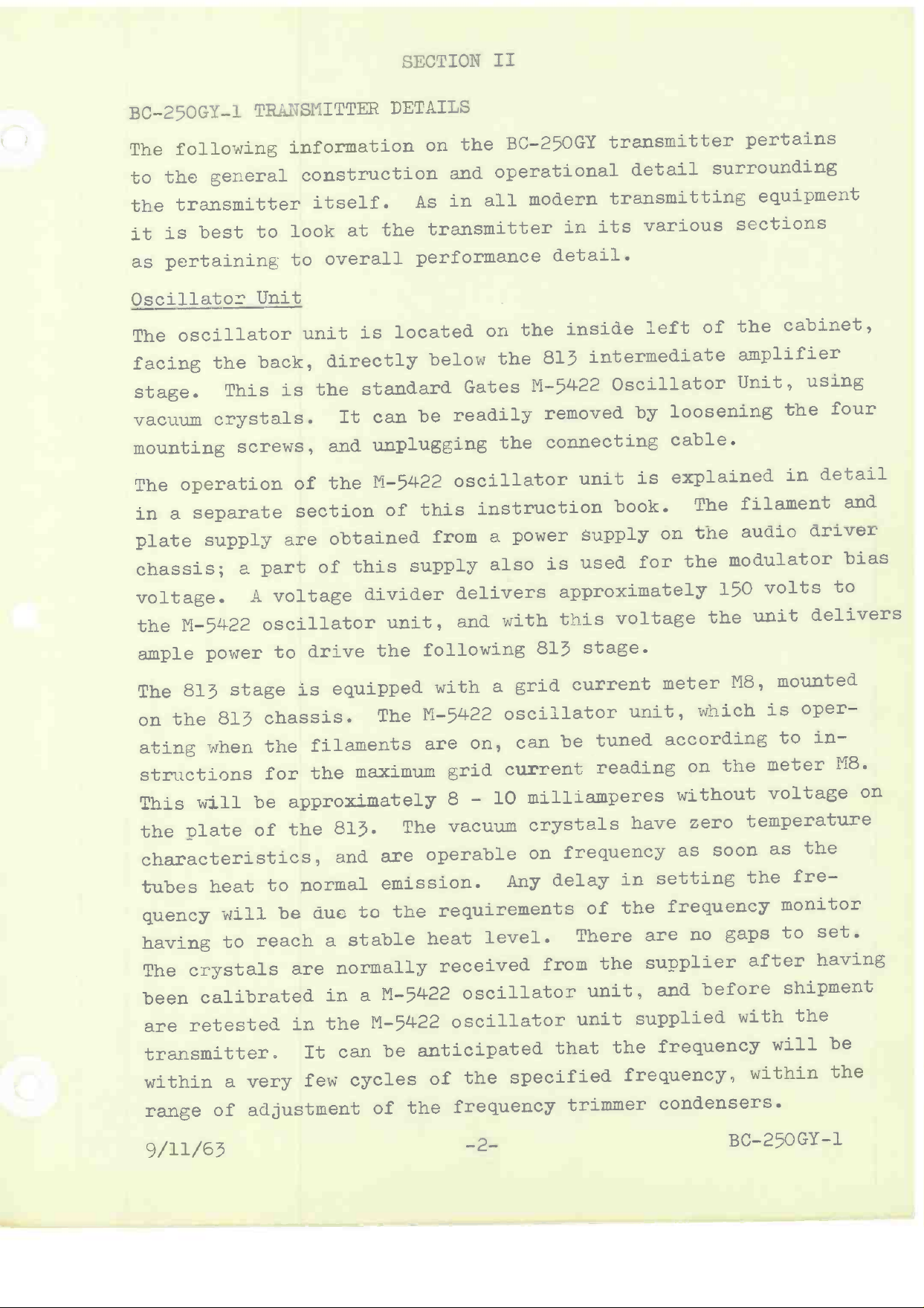
The
following
general
the
to
transmitter
the
is best
it
pertaining
as
Oscillator
The oscillator
facing
stage.
vacuum
mounting
The
in a
plate
operation
separate
supply
chassis;
voltage.
M -5422
the
ample
power
to
Unit
back,
the
This
is the
crystals.
screws,
are
a part
A voltage
oscillator
to
information
construction
itself.
the
unit
at
is located
look
to overall
directly
standard
It can
unplugging
and
M -5422
the
of
section
of
obtained
of
this
supply
divider
unit,
drive
the
BC -250GY
the
on
operational
and
modern
all
in
As
transmitter
performance
the
on
below
be
the
Gates
M -5422
readily
the
oscillator
from
instruction
a power
also
this
delivers
with
and
following
transmitter
detail
transmitting
various
its
in
detail.
inside
813
intermediate
left
Oscillator
removed
by
connecting
unit
is
supply
used
is
book.
on
for
approximately
this
813
voltage
stage.
pertains
surrounding
equipment
sections
the
of
amplifier
Unit,
loosening
cable.
explained
The
the
the
filament
audio
modulator
volts
150
unit
the
cabinet,
using
in
four
detail
and
the
driver
bias
to
delivers
The
on
813
the
ating
stage
813 chassis.
when
structions
This
the
will be
plate
is
the
for
filaments
the
approximately
the
of
characteristics,
normal
tubes
quency
heat
will
having
are
crystals
calibrated
retested
The
been
transmitter.
within
range
of
to
be
reach
to
are
in
It can
a very
few
adjustment
due
equipped
The
maximum
813.
and
The
are
emission.
the
to
stable
a
normally
in a
the
M -5422
M -5422
be
cycles
of
grid
on,
grid
8 -
a
oscillator
can
current
10
with
M -5422
are
vacuum
operable
Any
requirements
heat
level.
received
oscillator
oscillator
anticipated
of
the
the
frequency
specified
current
tuned
be
meter
unit,
reading
milliamperes
crystals
frequency
on
delay
There
from
unit
that
have
in
the
of
the
unit,
supplied
the
setting
are
supplier
and
frequency
frequency,
trimmer
condensers.
M8,
which
according
the
on
without
zero
as
temperature
soon
the
frequency
gaps
no
after
before
with
within
mounted
oper-
is
in-
to
meter
M8.
voltage
the
as
fre-
monitor
set.
to
having
shipment
the
will
be
the
on
9/11/63
-2- BC-250GY-1
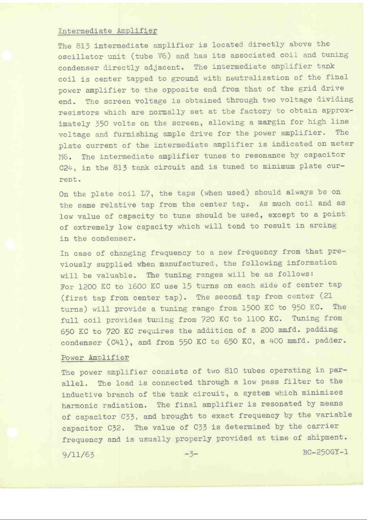
Intermediate
Amplifier
The 813
oscillator
condenser
coil
intermediate
unit (tube
directly
is
center
power amplifier
end.
The
resistors
imately 350
voltage
plate current
M6.
C24,
rent.
On
the
low
of
The intermediate
in
the plate
same
value
extremely
screen
which
volts on
furnishing
and
of
the 813 tank
coil
relative
of capacity
low capacity
amplifier
V6) and
adjacent.
tapped
to
voltage
are normally
to ground
the opposite
is obtained
the
screen,
ample
the
intermediate
amplifier
circuit
L7, the
tap
from
tune
to
is located
The
its associated
intermediate
has
with neutralization
end from
set
at the
allowing
drive
for
amplifier
tunes
and
is tuned
taps (when
the center
should
which
will tend
directly
that of
through
factory
a
the
to
used)
tap.
be
power
resonance
to
should
used,
to
above
coil
and
amplifier
the
of
the
two
voltage
to
margin
grid
obtain
high
for
amplifier.
is indicated
by capacitor
minimum
plate
always
much coil
As
except
result
to
in arcing
the
tuning
tank
final
drive
dividing
approx-
line
The
meter
on
cur-
on
be
and
a point
as
the condenser.
in
In case
of changing
viously supplied
valuable.
will
For 1200
(first
turns)
full coil
650
condenser
be
KC to
from center
tap
will
provide
provides
KC to 720
(C41),
1600
KC requires
Power Amplifier
The power
allel.
inductive
harmonic
capacitor
of
capacitor
frequency
amplifier
The
load
branch
radiation.
C33,
C32.
is usually
and
frequency
when
and from
manufactured,
The tuning
KC use
tap).
tuning
a
tuning
15
from
the addition
550
consists
is connected
the
of
and brought
The value
tank
The final
of
properly
to a
ranges
turns
The second
range
KC to
of two
new frequency
the
will
on
from
KC to
720
650
810
through
circuit,
amplifier
exact
to
determined
C33
is
provided
following
be as
each
1500
of
KC, a
side
tap
1100
200
a
from
KC to
KC.
400 mmfd.
tubes
pass
low
a
system
a
resonated
is
frequency
at
from
that
information
follows:
center
of
center
950
Tuning
mmfd.
padding
operating
filter
which
minimizes
by
the
by
by
time
the
carrier
shipment.
of
pre-
tap
(21
KC.
The
from
padder.
in par-
the
to
means
variable
9/11/63
-3-
BC-250GY-1
In
some
very
ser
amplifier
the antenna
mation
instances of
low
C33,
impedance
may be
as to the
will
immediately
antennas,
affected
not
and
resonate
would only
antenna
supplied
unusual
loading
the
as
applied
with
be
loading
or
the factory.
to
value
to normal
the load
in case
characteristics
conditions,
tank padding
of
charts
applied,
direct coupling,
of
particularly
conden-
the
and
it
if
would
be
infor-
should
be
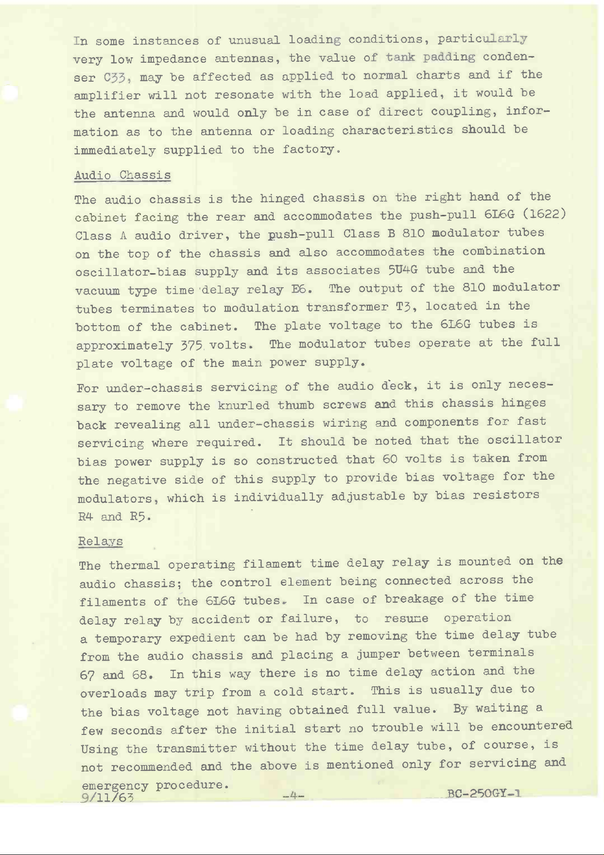
Audio
The audio
cabinet
Class
on the
oscillator
vacuum
tubes
bottom
Chassis
chassis
facing
A audio
top
of
-bias
type
time
terminates
the
of
approximately
plate
For
sary
back
servicing
bias
the
voltage of
under-
to
chassis
remove the
revealing
where
power
supply
negative
modulators,
the
is
rear
the
driver,
the chassis
supply
delay
modulation
to
cabinet.
volts.
375
main
the
servicing
knurled
under-
all
required.
is so
this
side
which
of
individually
is
hinged
and
the push
and
relay
accommodates
-pull
and
The
The modulator
also
its
E6.
plate
power
of
thumb
chassis
It should
constructed
supply
chassis
on
the push
Class
accommodates
associates
The output
transformer
voltage
tubes operate
supply.
the
audio
screws
wiring
that
to provide
deck,
and
and components
noted
be
60
adjustable
right
the
-pull
B 810
5Ú4G
T3, located
to
modulator
the combination
tube
of the
the
6L6G
is only
it
this chassis
that
volts
bias
by
the
is taken
voltage
bias
hand
of
6L6G
tubes
the
and
810
modulator
the
in
tubes
the
at
neces-
hinges
for
fast
oscillator
for
resistors
the
(1622)
is
full
from
the
R4 and
R5.
Relays
The thermal
audio
filaments
delay
a
from
67 and
overloads
the
few
Using
not
emergency
(4/11/63
chassis;
of
relay
temporary
the audio
68.
may
bias
voltage
seconds
transmitter
the
recommended
procedure.
operating
the
the
6L6G
filament
control
tubes.
by accident
expedient
can
chassis
In
this
trip
after
way there
from
having
not
the
initial
without
the
and
or
be
and
cold
a
above
time
element
In case
failure,
had
by
placing
no time
is
start.
obtained
start
time
the
mentioned
is
-4-
delay
being
to
relay
connected
of breakage
resume
removing
a jumper
delay
This
full
no
value.
trouble
delay
mounted
is
across
of
operation
the
between
time
terminals
action
is usually
By
for
be
of
servicing
will
tube,
only
BC-
on
the
the
time
delay
and
the
due
tube
to
waiting
encountered
course,
250GY
-1
the
a
is
and
oduïator
filament
the
the current
the circuit
contacts
normal
cause
operation,
the overload
contacts
contactor
to chatter,
occurs.
becomes
through
in series
were used
coil,
or
Both overload
resistors for
unshunted
gives a
shorted
required
about
at
overload
load
does not trip
ulators,
venting
operating
higher current
out on the
to trip
400 milliamperes,
does not trip
the
distortion
and
sower
ampliiier
return circuits.
sufficient,
auxiliary
an
with
the
high
modulation
armature
to operate
these
modulation
possibly
to pull
drop out,
relay coils
setting
the overload
current
rating.
is
resistors
the
respective
heavy
with normal
with
resistors
through
normal program.
also
load the
this
stages
These are normally
the contacts
relay
voltage
may provide
open.
directly
cycles
although
are
current
MA
300
Increasing
R27
and
relay.
enough
tuning
have
with normally
contactor
sufficient
If normally
in series
would
no
shunted
point.
and shunting
the amount
R28, raises
The relays
that
and the
In the
inductance
element.
overload
open.
close,
relays
completing
closed
coil.
current
closed
with
cause
overload
the plate
the
actually
by adjustable
The normal
with
that
the current
should
the power
amplifier
modulator
case
of
of the
the
coil,
in
When
Under
to
contactor
resistors
is
trip
over-
mod-
pre-
8008
The 8008 mercury
ature.
tube has
verse
the
Rectifier
If
a
direction,
transmitter
as-unattended
may become
directly
which
and
minor
Another
replaced
is
modifications
solution
transmitter
furnaces,
certain
adjusted
value
energized.
haust
the
fan
thermostat
around
tifiers
Q /11 /Fiji
could
degrees.
95
is
Tubes
temperature
the
tendency
and
excessive,
not
cabinet
such
Similarly,
operating
NOT recommended
vapor
rectifier
is too
to "arc-
resulting
is
operated
in a unheated
mercury
the
a type
by
nearly
so
by semi
is to
install
with a
that
so
as 75
installed
be
degrees,
if high
when the
Operation
are
too
conduct
voltage
back"
in
a
tubes
high or
or
high
where temperature
building,
vapor
using
xenon
sensitive
-conductor
a heating
thermostat
when
the temperature
the heating
to temperature,
or
rectifier
or
rectifiers.
element
control
temperature
top of
the
in
temperature
of
above
this
120
equipment
°F or
below
-5-
temper-
sensitive
low,
current
short
is a
where the
some
other
such
drops
element
is a problem,
the transmitter,
reached
with
45 °F
to
this
in the
circuit.
problem,
tubes
inert
or
inside
as used
below
will be
a
mercury
ambient.
25flGY
Re-
type
temperature
may
with
the
an
value
of
re-
When
such
be
gas
for
a
ex-
with
of
rec-
-1
Transformers
the
Several
of
terminals.
a.c.
line
nects
at the
to
always connects
terminal
specified
connecting
connecting
by
terminal
this
Wiring
The power
Most
local
ation
load
This transmitter
source.
#3.
operating
Detail
line connections
wiring
regulations
will
current
It will
modification,
transformers
With
terminal
to
the
Transformer
manual.
regulations
meet
is
but
these
for
#3
load.
line
should
all
8.5
requirements.
amperes.
requires
not
operate
designed
is
are provided
transformers,
terminal
to
normal
The secondary
instead
#2
terminal
to
voltage
of
##4 instead
diagrams
made
are
require
a service
be checked
The wire
volts
230
on a
to
208
operate
voltage
of
The other
one
#1.
with
side
output
voltage
terminal
included
are
directly
may be
#3,
of connecting
to
switch
so that
The maximum
size
a.c.
the
should
single
volt power
either
change
the
on
incoming
side con-
the
secondary
raised
lowered
or
elsewhere
fuse
the
with
fuses.
initial
normal
phase
transmitter
#8
be
power
source
cycles
50
on
by
to
in
block
A7.
The
install-
or #10.
without
or
cycles.
60
The audio
the
rear
should
working
may
If
put pad,
having
mitter
of
be
the
be
equally
had
output
a
and
response.
The
frequency
located
modulation
The
Both
will
used.
are
pins
not
Sometimes
high
so
9/11/63
input
line
modulator
shielded
a
well
changing
by
amplifier
is advisable
it
5
loss
of
amplifier
monitor
radio
the
on
monitor
are connected
connected
be
audio
that
seldom
connects
panel
pair.
with
primary
to the
to
DB to
6
or
to
and
jack
frequency
connection
together.
wrong.
cable
are the
terminal
the
to
(right
The transmitter
either
side,
ohmage.
taps
on
the
transmitter
fixed
side
is for
a
no
no
for
panel
insert
assure
introduce
is fitted
This
Small
is tried,
size
results
-6-
board
facing
input
Other
input
from
is
input
transformer
does not
pad,
"H"
reaction
errors
single
a
at the
two
a
insures
-axial
co
the
losses
between
in
pin
bottom
pin connector.
that
cable
and
satisfactory.
at the
rear).
bottom
500/600
impedances
have
an
500/500
trans-
frequency
connector
rear.
the
two
should
capacities
250GY
BC-
This
ohms,
T8.
outohms
lines
be
-1
on
go
transmitter
should
The
the
to
top
the
of
radio
The
itself
lations.
recommended.
down
and connecting
inside
Connecting
the
the
cabinet
grounded
be
radio
the
frequency
cabinet
system
In some
installations,
transmitter,
strap
a
to
Load
should
cable
by
adjacent
ground.
behind
from
well
be
to
output,
to
least
At
the
there
grounded.
meet
underwriters'
which
feedthru
the
2"
a
this
to
lead
side
the
the
is
copper
might
panel
system
The
cabinet
cabinet
bowl,
strap
be
the
to
ground.
regu-
stud
should
is
dressed
base,
The
coaxial
antenna
connects
transmitter.
wire
line
that
mitter
be
the
ing
transmission
should
the
ground
cabinet.
brought
up
convenient
engineer's
open
or
to
In the
firmly
be
path
Where
through
locations
eye.
wire
the
case
line,
secured
will
the
transmission
feedthru
of
the
ground
not
desired,
bottom
will
as
insulators
coaxial
the
to
have
the
of
be
line
or
on
transmission
portion
top
travel
to
coaxial
the
quickly
of
the
of
transmission
cabinet
obvious
the
the
direct
top
line
transmission
the
cabinet
through
any
at
of
or
the
to
coupled
the
open
also,
tríns-
line
number
the
install-
so
may
of
9/11/63
-7- BC-250GY-1
SECTION
III
General
Before
Operational
proceeding
necessary
portion
of the
1 -
2 -
3 - Froper
4 -
5 - A
6 -
7 - Looking
8 -
9 -
with
things
to
transmitter.
Proper
Froper
line
location
termination
equipment.
for
of
shipping
Removal
used
recheck
have
Complete
and
been
check
wrench
connections
have
been
over
making
Making
that
main
sure
certain
ground
the
ground
IMPORTANT.
Making
certain
correction
connecting
INITIAL
Procedure
initial
before
be
the
done
voltage
all
of
of
-down
tie
all
purposes.
be sure
to
installed
the
of
sure
be
to
that
brought
all
that
of
AT
taps
to
could
down
wiring
everything
the
to
the
LEAST
that
have
terminal
TUNE
Briefly,
to
-UP
fuse
tubes
the
any
-up
voltage
tune
check
block
in
antenna
straps
components
properly.
transmitter
bolts,
all
possibly
securely.
broken
for
is
transmitter
the
transmitter
antenna
COPPER
2"
system.
transformers
one
side
#1.
let
the
A?.
the
and
sockets.
or
other
removed
with
screws
work
solder
secure.
well
is
is
STRAP
with
the
of
recheck
us
applied
is
following
dummy
antenna
materials
for
a
loose
shipment
screwdriver
and
other
shipment
in
connections,
grounded
the
IS
to
VERY
tied
THIS
RECOMMENDED.
voltage
supply
line
the
any
to
list:
and
-
10
In case
the
building,
the
varied
equipment.
ground
formance
With
closed
the
and
"Filament
power
unit
tions
supply
tuned
is
for
9/11/63
Making
and
and
output
sure
that
that
wire
the
no
transmitter
particular
Additional
potentials
and
low
noise.
transmitter
power
ON"
supplied
switch
for
the
according
this
unit.
audio
wiring
shields
input
or
wire
power
a
located
is
attention
ground
highly
is
ready
Sl,
M -5422
When
to
to
lights
oscillator
the
to
the
-8-
the
been
has
have
been
runs
cable.
on
must
in
the
be
busses
important
operate,
transmitter.
tube
the
directions
transmitter
properly
properly
the
same
upper
and
to
elimination
paid
for
the
service
filaments
unit.
given
has
shielded
grounded,
cable
floor
of
grounding
good
per-
switch
Pressing
and
The
oscillator
the
in
been
factory
-250GY
BC
an
as
a
of
of
is
the
the
instruc-
-1
tested
the
on
current
which
of
should
the tube.
frequency,
on
tuning.
The 813 stage
meter, and
8 -
be
this
the
10 milliamperes
should
is provided
oscillator
amount
tuned
with
to
no
more
than
with a convenient
for
no
maximum
voltage
grid
on
check
a
grid
current,
the plate
Before
pick -up coil
far
the modulation
stats
clockwise.
applying
L12, for
removed from
monitor
R4
R5
and
Set the
Remove the plate
making
sure
Disconnect
and
2 or
30 seconds,
light
will light.
voltage
close.
contactor
ON condition,
the connector
the
whichever
3
"ON" switch
primary
the
Pressing the
to open.
opening
high voltage,
the
minimum
the
to
tank
input.
maximum
neutralizing
connector
of
is used.
time
delay
With
should
S2
high
With
the
set
coupling,
possible
coil
bias
as
the two
Set
voltage,
condenser
from
is not
the plate
one
grounded.
When
E6 closes
door closed,
the
relay
back
cause
voltage
the contactor
back
"OFF"
door should
modulation
the
right
at
so as
modulator
that
of the
transformer
the filaments
is,
C28
8008
and
at half
rectifier
Tl, terminals
the
pressing
the plate
switch
closed
contactor
should
in
cause
monitor
angles
not
to
bias
fully
capacity.
have
been
"FILAMENT"
the
cause
high
the
the
contactor
and
as
overload
rheo-
counter-
tubes,
1
on
high
E4 to
this
voltage
open.
to
the
the
high
insulating
El
and
and cause
Opening
S4,
dowel or
relays
operate
armatures
NEVER
If
be touched
the
control
exists and
voltage
incurred
be
With
transformer
the
control
transformer
adjusted.
9/11/63
door
voltage
then
these
of
should
while
may
and blocking
control
stick,
E2.
the
In each
plate
relays
with the
circuit
be
does
remedied
disconnected,
testing
circuits
reconnected,
be
holding
or
then
can
push
the
case
armatures
contactor
the
in
are
body.
not
operate
before
no damage
the control
functioning
the
and
-9-
the
be
the
to open.
220
as described,
door
closed.
of
auxiliary
volt
circuit
continuing.
equipment
to
circuits.
properly,
ridio
frequency
interlock
With
the
a
overload
relay
CAUTION:
and
some
With
the
the
high
BC-
switch
wooden
E3 should
The
should
fault
high
should
voltage
circuits
250GY
-1
 Loading...