

GatesAir ULXATSC User Manual

User MANUAL
888-2715-001
Maxiva ULX A TSC Series
Digital T ransmitter
Maxiva ULX A TSC Series
Digital Transmitter
T.M. No. 888-2715-001
© Copyright Harris Corporation 2010
All rights reserved
February 19, 2010
Rev: A

ii 888-2715-001 2/19/10
WARNING: Disconnect primary power prior to servicing.

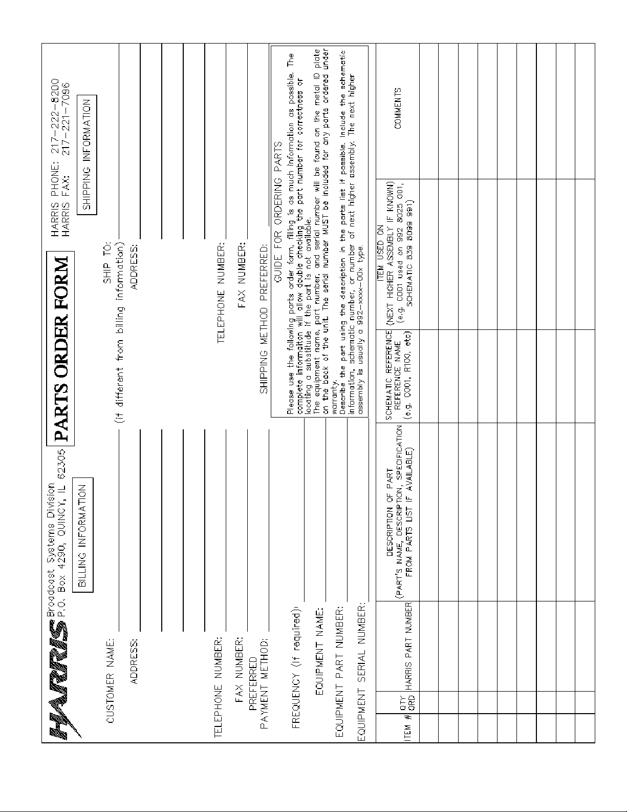
Technical Assistance
Technical and troubleshooting assistance for HARRIS Transmission products is available from
HARRIS Field Service (factory location: Quincy, Illinois, USA) during normal business hours (8:00
AM - 5:00 PM Central Time). Telephone +1-217-222-8200 to contact the Field Service Department;
FAX +1-217-221-7086; or E-mail questions to tsupport@harris.com.
Emergency service is available 24 hours a day, seven days a week, by telephone only.
On-line assistance, including technical manuals, white papers, software downloads, and service
bulletins, is available at http://support.broadcast.harris.com/eservice_enu.
Address written correspondence to Field Service Department, HARRIS Broadcast Communications
Division, P.O. Box 4290, Quincy, Illinois 62305-4290, USA. For other global service contact
information, please visit: http://www.broadcast.harris.com/contact.
NOTE: For all service and parts correspondence, you will need to provide the Sales Order number,
as well as the Serial Number for the transmitter or part in question. For future reference, record those
numbers here: ___________________/____________________
Please provide these numbers for any written request, or have these numbers ready in the event you
choose to call regarding any Service, or Parts requests. For warranty claims it will be required, and
for out of warranty products, this will help us to best identify what specific hardware was shipped.
Replaceable Parts Service
Replacement parts are available from HARRIS Service Parts Department from 7:00 AM to 11:00 PM
Central Time, seven days a week. Telephone +1-217-222-8200 or email servicepartsreq@harris.com
to contact the Service Parts Department.
Emergency replacement parts are available by telephone only, 24 hours a day, seven days a week
by calling +1-217-222-8200.
Unpacking
Carefully unpack the equipment and preform a visual inspection to determine if any apparent damage
was incurred during shipment. Retain the shipping materials until it has been verified that all
equipment has been received undamaged. Locate and retain all PACKING CHECK LISTs. Use the
PACKING CHECK LIST to help locate and identify any components or assemblies which are
removed for shipping and must be reinstalled. Also remove any shipping supports, straps, and
packing materials prior to initial turn on.
Returns And Exchanges
No equipment can be returned unless written approval and a Return Authorization is received from
HARRIS Broadcast Communications Division. Special shipping instructions and coding will be
provided to assure proper handling. Complete details regarding circumstances and reasons for return
are to be included in the request for return. Custom equipment or special order equipment is not
returnable. In those instances where return or exchange of equipment is at the request of the
customer, or convenience of the customer, a restocking fee will be charged. All returns will be sent
freight prepaid and properly insured by the customer . When communicating with HARRIS Broadcast
Communications Division, specify the HARRIS Order Number or Invoice Number.
2/19/10 888-2715-001 iii
WARNING: Disconnect primary power prior to servicing.

iv 888-2715-001 2/19/10
WARNING: Disconnect primary power prior to servicing.

Manual Revision History
Maxiva ULX ATSC Series Digital Transmitter User Manual
REV. DATE ECN Pages Affected
A FEB 2010 - Created
2/19/10 888-2715-001 MRH-1
WARNING: Disconnect primary power prior to servicing.

MRH-2 888-2715-001 2/19/10
WARNING: Disconnect primary power prior to servicing.
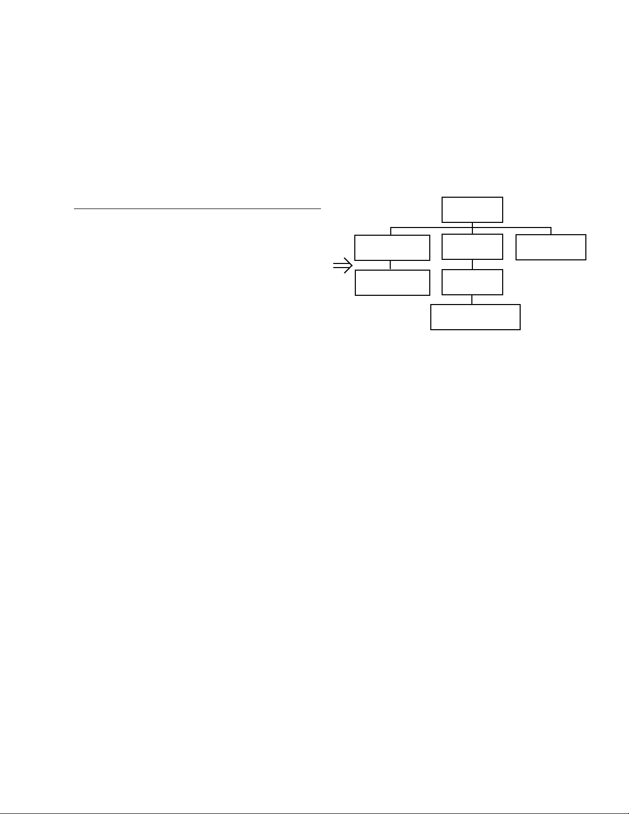
Guide to Using Harris Parts List Information
The Harris Replaceable Parts List Index portrays a tree structure with the major items being leftmost in the index.
The example below shows the Transmitter as the highest item in the tree structure. If you were to look at the bill
of materials table for the Transmitter you would find the Control Cabinet, the PA Cabinet, and the Output
Cabinet. In the Replaceable Parts List Index the Control Cabinet, PA Cabinet, and Output Cabinet show up one
indentation level below the Transmitter and implies that they are used in the Transmitter. The Controller Board is
indented one level below the Control Cabinet so it will show up in the bill of material for the Control Cabinet.
The tree structure of this same index is shown to the right of the table and shows indentation level versus tree
structure level.
Example of Replaceable Parts List Index and equivalent tree structure:
Replaceable Parts List Index Part Number Page
Table 7-1. Transmitter 994 9283 001 7-2
Table 7-2. Control Cabinet 992 9244 002 7-3
Table 7-3. Controller Board 992 8344 002 7-6
Table 7-4. PA Cabinet 992 9400 002 7-7
Table 7-5. PA Amplifier 994 7894 002 7-9
Table 7-6. PA Amplifier Board 992 7904 002 7-10
Table 7-7. Output Cabinet 992 9450 001 7-12
The part number of the item is shown to the right of the description as is the page in the manual where the bill for
that part number starts. Inside the actual tables, four main headings are used:
Control Cabinet
992 9244 002
Controller Board
992 8344 002
Transmitter
994 9283 001
PA Cabinet
992 9400 002
PA Amplifier
992 7894 002
PA Amplifier Board
992 7904 002
Output Cabinet
992 9450 001
• Table #-#. ITEM NAME - HARRIS PART NUMBER - this line gives the information that corresponds
to the Replaceable Parts List Index entry;
• HARRIS P/N column gives the ten digit Harris part number (usually in ascending order);
• DESCRIPTION column gives a 25 character or less description of the part number;
• REF. SYMBOLS/EXPLANATIONS column 1) gives the reference designators for the item (i.e., C001,
R102, etc.) that corresponds to the number found in the schematics (C001 in a bill of material is equiva
lent to C1 on the schematic) or 2) gives added information or further explanation (i.e., “Used for 208V
operation only,” or “Used for HT 10LS only,” etc.).
NOTE: Inside the individual tables some standard conventions are used:
-
• A # symbol in front of a component such as #C001 under the REF. SYMBOLS/EXPLANATIONS col-
umn means that this item is used on or with C001 and is not the actual part number fo r C001.
• In the ten digit part numbers, if the last three numbers are 000, the item is a part that Harris has pur-
chased and has not manufactured or modified. If the last three numbers are other than 000, the item is
either manufactured by Harris or is purchased from a vendor and modified for use in the Harris product.
• The first three digits of the ten digit part number tell which family the part num ber belongs to - for
example, all electrolytic (can) capacitors will be in the same family (524 xxxx 000). If an electrolytic
(can) capacitor is found to have a 9xx xxxx xxx part number (a number outside of the normal family of
numbers), it has probably been modified in some manner at the Harris factory and will therefore show
up farther down into the individual parts list (because each table is normally sorted in ascending order).
Most Harris made or modified assemblies will have 9xx xxxx xxx numbers associated with them.
The term “SEE HIGHER LEVEL BILL” in the description column implies that the reference designated part
number will show up in a bill that is higher in the tree structure. This is often the case for components
that may be frequency determinant or voltage determinant and are called out in a higher level bill
structure that is more customer dependent than the bill at a lower level.
2/19/10 888-2715-001 vii
WARNING: Disconnect primary power prior to servicing.

viii 888-2715-001 2/19/10
WARNING: Disconnect primary power prior to servicing.
2/19/10 888-2715-001 ix
WARNING: Disconnect primary power prior to servicing.

x 888-2715-001 2/19/10
WARNING: Disconnect primary power prior to servicing.

!
WA RN IN G:
TTHE CURRENTS AND VOLTAGES IN THIS EQUIPMENT ARE DANGEROUS.
PERSONNEL MUST AT ALL TIMES OBSERVE SAFETY WARNINGS, INSTRUC
TIONS AND REGULATIONS.
-
This manual is intended as a general guide for trained and qualified personnel who are aware
of the dangers inherent in handling potentially hazardous electrical/electronic circuits. It is not
intended to contain a complete statement of all safety precautions which should be observed
by personnel in using this or other electronic equipment.
The installation, operation, maintenance and service of this equipment involves risks both to
personnel and equipment, and must be performed only by qualified personnel exercising due
care. HARRIS CORPORATION shall not be responsible for injury or damage resulting from
improper procedures or from the use of improperly trained or inexperienced personnel
performing such tasks. During installation and operation of this equipment, local building
codes and fire protection standards must be observed.
The following National Fire Protection Association (NFPA) standards are recommended as
reference:
- Automatic Fire Detectors, No. 72E
- Installation, Maintenance, and Use of Portable Fire Extinguishers, No. 10
- Halogenated Fire Extinguishing Agent Systems, No. 12A
!
WA RN IN G:
ALWAYS DISCONNECT POWER BEFORE OPENING COVERS, DOORS, ENCLOSURES, GATES, PANELS OR SHIELDS. ALWAYS USE GROUNDING STICKS
AND SHORT OUT HIGH VOLTAGE POINTS BEFORE SERVICING. NEVER MAKE
INTERNAL ADJUSTMENTS, PERFORM MAINTENANCE OR SERVICE WHEN
ALONE OR WHEN FATIGUED.
Do not remove, short-circuit or tamper with interlock switches on access covers, doors,
enclosures, gates, panels or shields. Keep away from live circuits, know your equipment and
don’t take chances.
!
WA RN IN G:
IN CASE OF EMERGENCY ENSURE THA T POWER HAS BEEN DISCONNECTED.
!
WA RN IN G:
IF OIL FILLED OR ELECTROLYTIC CAPACIT ORS ARE UTILIZED IN YOUR
EQUIPMENT, AND IF A LEAK OR BULGE IS APPARENT ON THE CAPACITOR
CASE WHEN THE UNIT IS OPENED FOR SERVICE OR MAINTENANCE, ALLOW
THE UNIT TO COOL DOWN BEFORE ATTEMPTING TO REMOVE THE DEFEC
TIVE CAP A CITOR. DO NOT ATTEMPT TO SERVICE A DEFECTIVE CAPACITOR
WHILE IT IS HOT DWHILE IT IS HOT DUE TO THE POSSIBILITY OF A CASE RUP
TURE AND SUBSEQUENT INJURY.
-
-
2/19/10 888-2715-001 xi
WARNING: Disconnect primary power prior to servicing.
xii 888-2715-001 2/19/10
WARNING: Disconnect primary power prior to servicing.

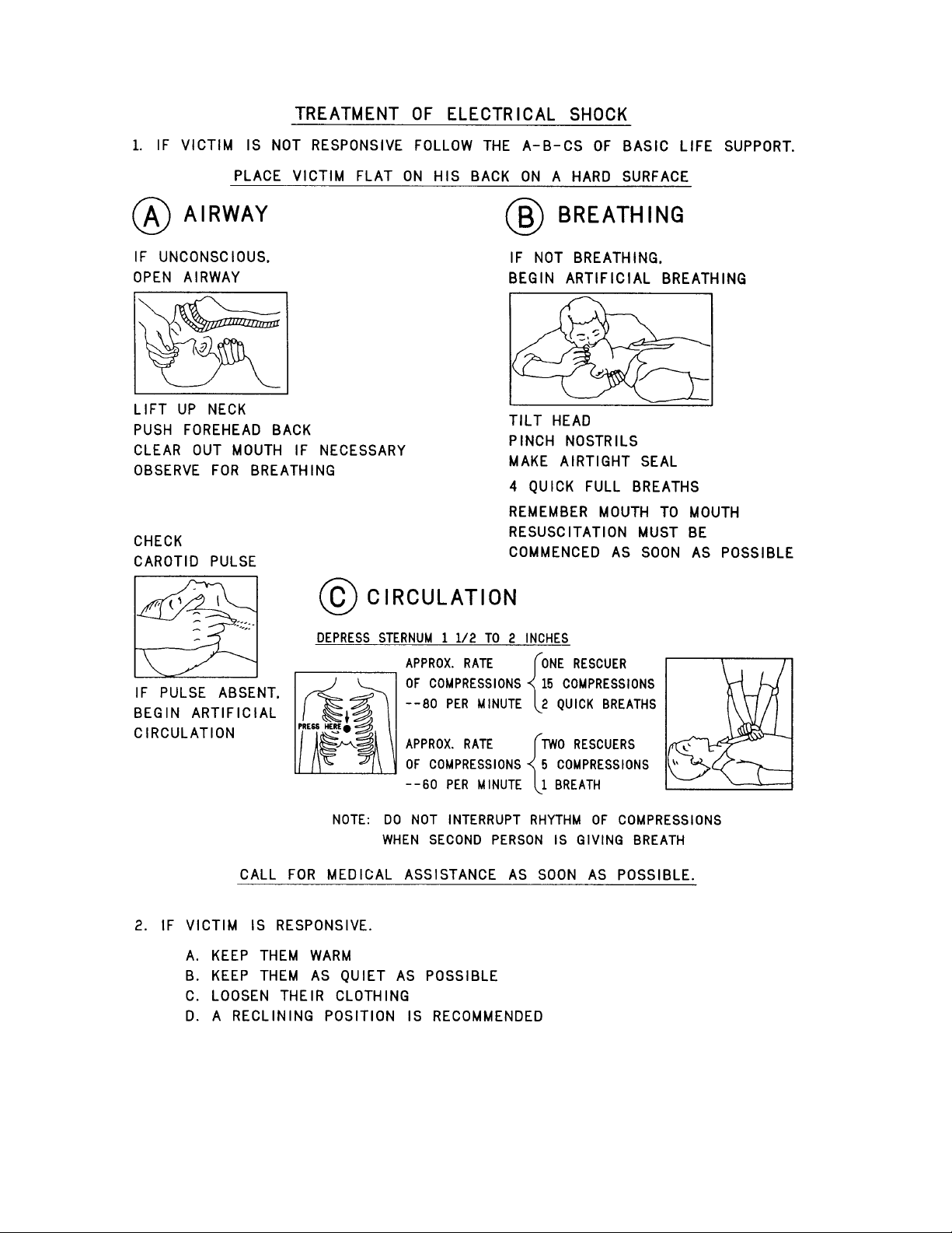
FIRST-AID
Personnel engaged in the installation, operation, maintenance or servicing of this equipment
are urged to become familiar with first-aid theory and practices. The following information is
not intended to be complete first-aid procedures, it is a brief and is only to be used as a
reference. It is the duty of all personnel using the equipment to be prepared to give adequate
Emergency First Aid and there by prevent avoidable loss of life.
Treatment of Electrical Burns
1. Extensive burned and broken skin
a. Cover area with clean sheet or cloth. (Cleanest available cloth
article.)
b. Do not break blisters, remove tissue, remove adhered particles of
clothing, or apply any salve or ointment.
c. Treat victim for shock as required.
d. Arrange transportation to a hospital as quickly as possible.
e. If arms or legs are affected keep them elevated.
NOTE:
If medical help will not be available within an hour and the victim is conscious and
not vomiting, give him a weak solution of salt and soda: 1 level teaspoonful of salt
and 1/2 level teaspoonful of baking soda to each quart of water (neither hot or
cold). Allow victim to sip slowly about 4 ounces (a half of glass) over a period of
15 minutes. Discontinue fluid if vomiting occurs. (Do not give alcohol.)
2. Less severe burns - (1st & 2nd degree)
a. Apply cool (not ice cold) compresses using the cleanest available
cloth article.
b. Do not break blisters, remove tissue, remove adhered particles of
clothing, or apply salve or ointment.
c. Apply clean dry dressing if necessary.
d. Treat victim for shock as required.
e. Arrange transportation to a hospital as quickly as possible.
f. If arms or legs are affected keep them elevated.
REFERENCE:
ILLINOIS HEART ASSOCIATION
AMERICAN RED CROSS ST ANDARD FIRST AID AND PERSONAL SAFETY
MANUAL (SECOND EDITION)
2/19/10 888-2715-001 xiii
WARNING: Disconnect primary power prior to servicing.

xiv 888-2715-001 2/19/10
WARNING: Disconnect primary power prior to servicing.

Table of Contents
Section 1
Introduction
Purpose of This Manual . . . . . . . . . . . . . . . . . . . . 1-1
General Description. . . . . . . . . . . . . . . . . . . . . . . . 1-2
Maxiva ATSC Series Transmitter Models . . . . . 1-4
System Block Diagram. . . . . . . . . . . . . . . . . . . . 1-4
Transmitter Control System . . . . . . . . . . . . . . . . 1-5
Transmitter RF Power Control. . . . . . . . . . . . . . 1-7
Graphical User Interface . . . . . . . . . . . . . . . . . . . . . .1-7
Control System Communications. . . . . . . . . . . . 1-7
Software Updates. . . . . . . . . . . . . . . . . . . . . . . . . . . .1-8
Remote Control . . . . . . . . . . . . . . . . . . . . . . . . . . . . .1-8
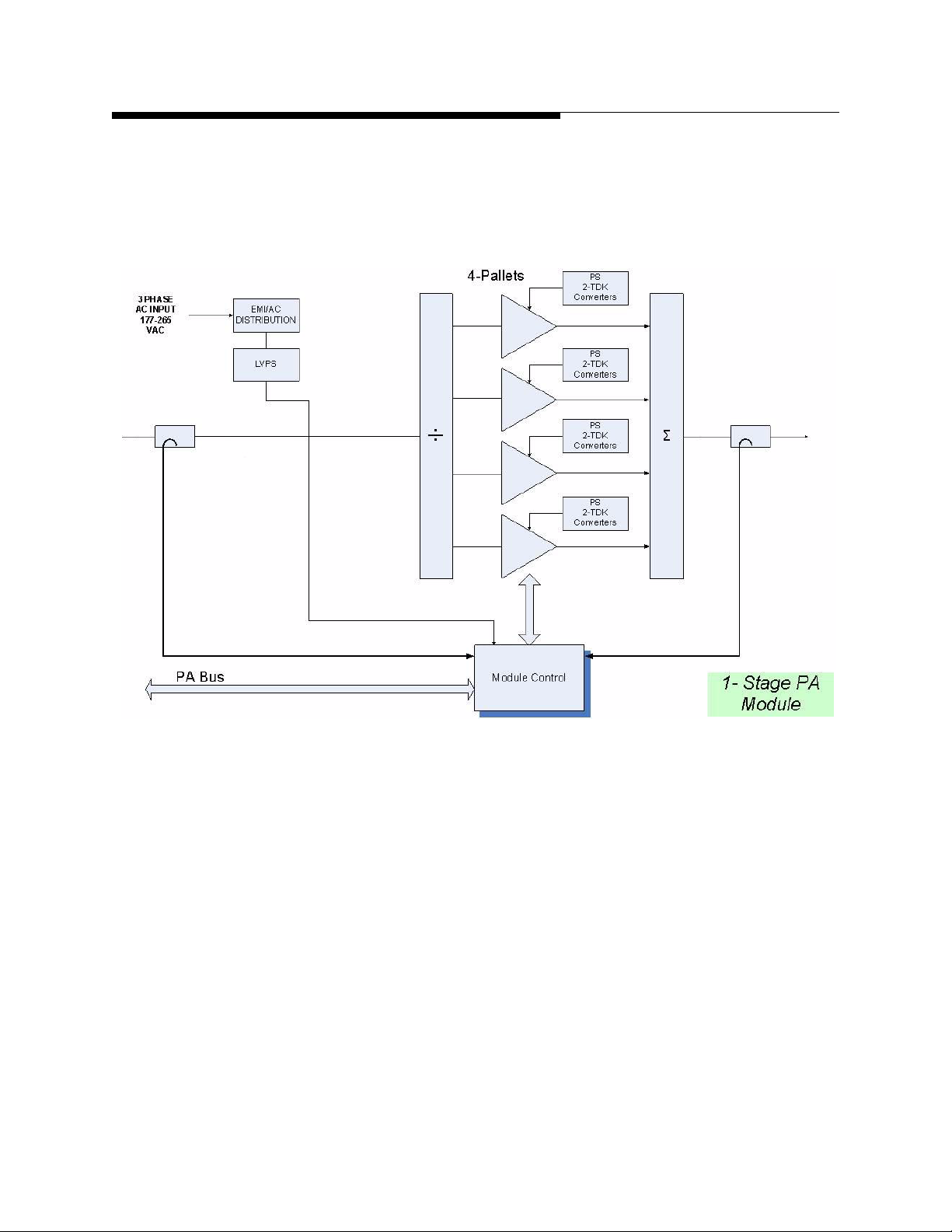
PA Module . . . . . . . . . . . . . . . . . . . . . . . . . . . . . 1-8
Module Control . . . . . . . . . . . . . . . . . . . . . . . . . . . .1-12
Transmitter Power Supplies . . . . . . . . . . . . . . . 1-13
Cooling System. . . . . . . . . . . . . . . . . . . . . . . . . 1-13
Cooling System Control Panel . . . . . . . . . . . . . . . .1-15
Pump Module/Heat Exchanger . . . . . . . . . . . . . . . .1-18
Heat Exchanger Fan Control. . . . . . . . . . . . 1-19
Pump Operation/Control Logic. . . . . . . . . . 1-19
PA Module and Combiner Cold Plates . . . . . . . . . .1-20
M2X Multimedia Exciter . . . . . . . . . . . . . . . . . 1-22
General Specifications. . . . . . . . . . . . . . . . . . . . . 1-23
Admin Setup (Local GUI Only) . . . . . . . . . . . . . . . 2-23
System Setup. . . . . . . . . . . . . . . . . . . . . . . . . . . . . .2-24
Cabinet Setup. . . . . . . . . . . . . . . . . . . . . . . . . . . . . .2-25
System and Cabinet Power Calibrate . . . . . . . . . . .2-26
System Version Screen . . . . . . . . . . . . . . . . . . . . . .2-26
System Network Screen . . . . . . . . . . . . . . . . . . . . .2-27
GUI Menu Structures . . . . . . . . . . . . . . . . . . . . . .2-28
Section 3
Diagnostics
Introduction. . . . . . . . . . . . . . . . . . . . . . . . . . . . . . .3-1
GUI System Log. . . . . . . . . . . . . . . . . . . . . . . . . . .3-2
Maxiva Three-Strike Fault Actions. . . . . . . . . . . . .3-3
Reflected Power Faults. . . . . . . . . . . . . . . . . . . . .3-3
Module Faults. . . . . . . . . . . . . . . . . . . . . . . . . . . .3-3
Fault Tables. . . . . . . . . . . . . . . . . . . . . . . . . . . . . . .3-5
Section 2
Operation
Introduction. . . . . . . . . . . . . . . . . . . . . . . . . . . . . . 2-1
Transmitter Control Panel. . . . . . . . . . . . . . . . . . . 2-1
Hardware Control Buttons . . . . . . . . . . . . . . . . . 2-2
Graphical User Interface (GUI). . . . . . . . . . . . . . . 2-4
Global Status and Navigation. . . . . . . . . . . . . . . 2-4
GUI Home Screen. . . . . . . . . . . . . . . . . . . . . . . . . 2-7
Drive Chain Main Menu . . . . . . . . . . . . . . . . . . . . 2-9
Drive Chain Faults . . . . . . . . . . . . . . . . . . . . . . 2-10
Drive Chain Meters . . . . . . . . . . . . . . . . . . . . . 2-11
Power Amp Main Menu . . . . . . . . . . . . . . . . . . . 2-13
PA Faults. . . . . . . . . . . . . . . . . . . . . . . . . . . . . . 2-14
Output Main Screen . . . . . . . . . . . . . . . . . . . . . . 2-15
Output Faults . . . . . . . . . . . . . . . . . . . . . . . . . . 2-16
Power Supply Main Menu. . . . . . . . . . . . . . . . . . 2-17
PS Faults. . . . . . . . . . . . . . . . . . . . . . . . . . . . . . 2-18
System Main Menu . . . . . . . . . . . . . . . . . . . . . . . 2-19
System Faults . . . . . . . . . . . . . . . . . . . . . . . . . . 2-20
System Fault Log . . . . . . . . . . . . . . . . . . . . . . . 2-20
System Service . . . . . . . . . . . . . . . . . . . . . . . . . 2-22
1

Table of Contents
2

Maxiva ULX ATSC Series
User Manual
Section 1 Introduction
1.1 Purpose of This Manual
This user manual contains the information pertaining to the Maxiva ULX Series, solidstate, UHF, ATSC digital TV transmitter. The various sections of this technical manual
provide the following types of information.
• Section 1, Introduction, provides general manual layout, photos, equipment descrip-
tion, block diagram and general specifications.
• Section 2, Operation, provides operation and navigation information for the Graphi-
cal User Interface or GUI as well as identification and functions of all external panel
controls and indicators.
1
• Section 3, Diagnostics, provides detailed fault information and diagnostic procedures
to the board level.
2/19/10 888-2715-001 1-1
WARNING: Disconnect primary power prior to servicing.
Maxiva ULX ATSC Series
Section 1 Introduction
1.2 General Description
This section contains a general description of the Maxiva ULX Series ATSC digital
television transmitters. Included in this section will be descriptions of the Control
System, Power Amplifier, block diagrams of the different models and system
specifications.
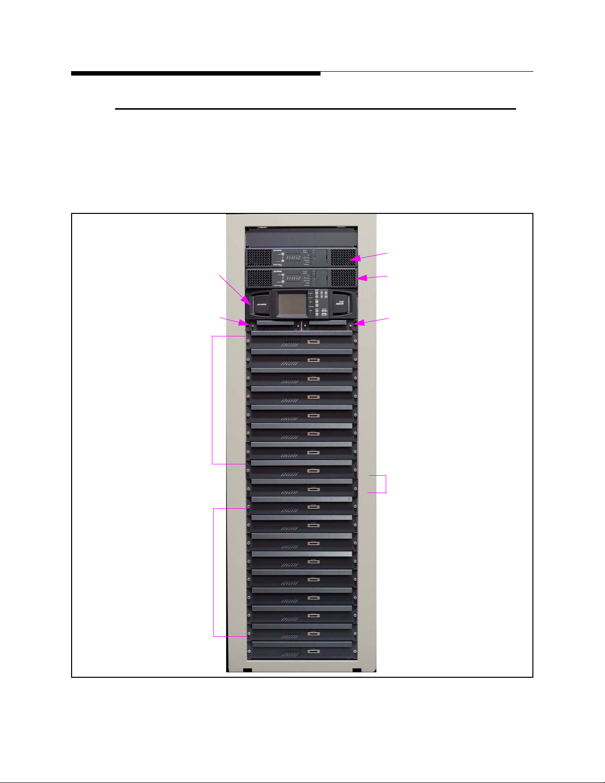
TCU System Controller
Redundant Pre-Driver A
User Manual
Apex M2X Exciter A
Apex M2X Exciter B
Redundant Pre-Driver B
18
PA Slots 11-18
PA Slots 1-8
A
B
11
Redundant Drivers
IPA A (slot 10)
IPA B (slot 9)
8
1
Figure 1-1 ULX-12300AT Front View
1-2 888-2715-001 2/19/10
WARNING: Disconnect primary power prior to servicing.
Maxiva ULX ATSC Series
User Manual
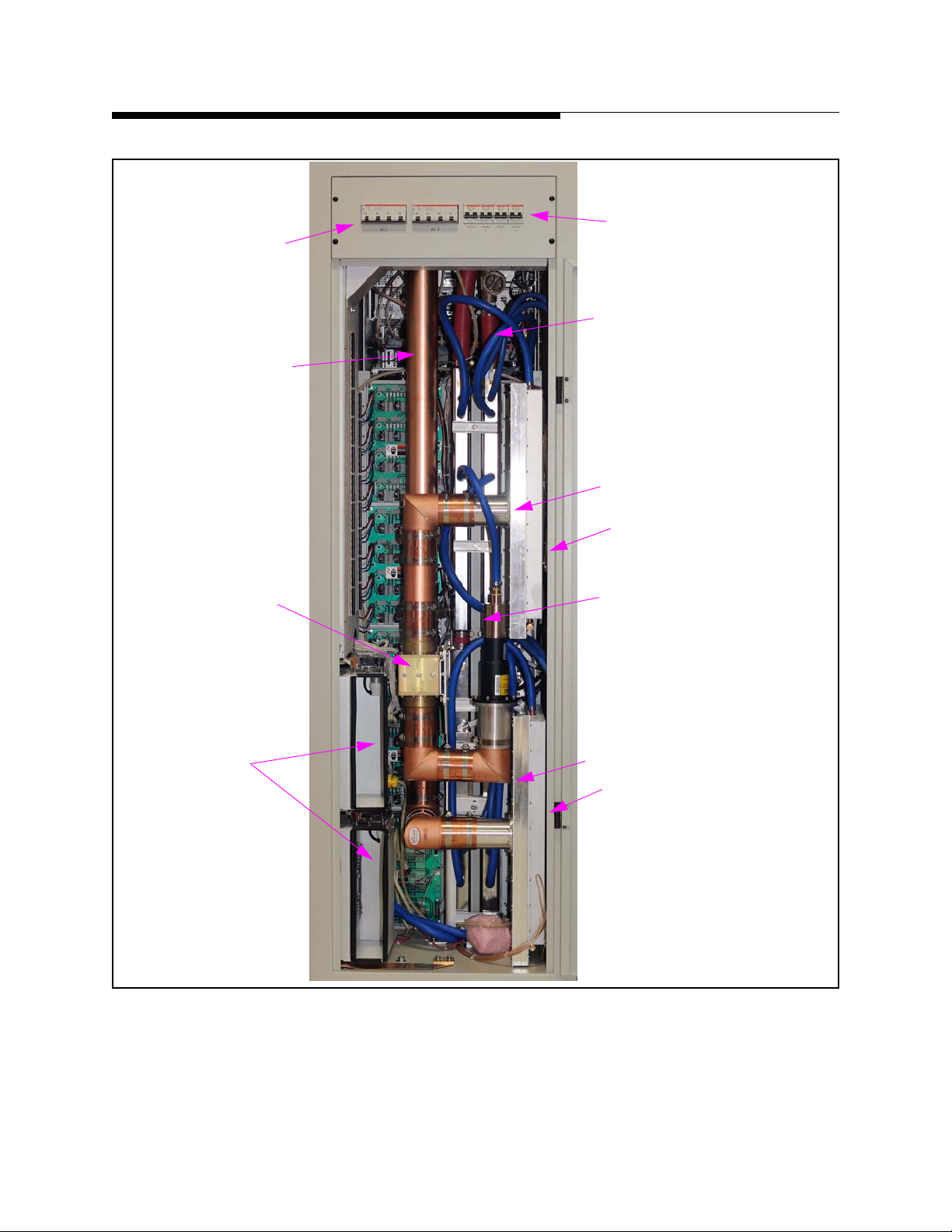
.
Main Breakers
RF Output Line
Section 1 Introduction
Control Breakers
Coolant Hoses In/Out
Upper 8 Way Combiner
Upper 8 Way Splitter
3dB Combiner
Redundant Cabinet
Blowers (2)
Final Reject Load
Lower 8 Way Combiner
Lower 8 Way Splitter
Figure 1-2 ULX 12300AT Rear View
2/19/10 888-2715-001 1-3
WARNING: Disconnect primary power prior to servicing.
Maxiva ULX ATSC Series
Section 1 Introduction
User Manual
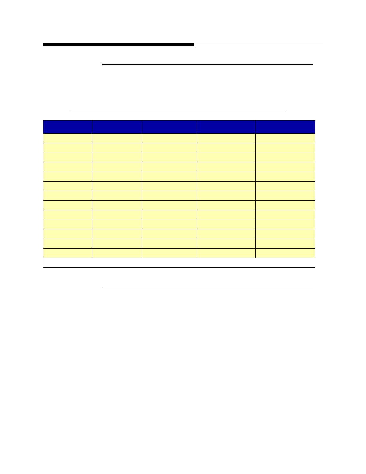
1.2.1 Maxiva ATSC Series Transmitter Models
The Maxiva ULX Series ATSC transmitter is available in 13 liquid cooled power levels.
The models are listed below in Table 1-1
Table 1-1 Maxiva ATSC Series Transmitter Models
Tx Models Cabinets PA Modules Output Power Primary Cooling
ULX1600AT 1 2 1600W LIQUID
ULX-2400AT 1 3 2400W LIQUID
ULX-3200AT 1 4 3200W LIQUID
ULX-4700AT 1 6 4700W LIQUID
ULX-6300AT 1 8 6300W LIQUID
ULX-7600AT 1 10 7600W LIQUID
ULX-9200AT 1 12 9200W LIQUID
ULX-12300AT 1 16 12.3 kW LIQUID
ULX-13400AT 2 18(12+6) 13.4 kW LIQUID
ULX-17800AT 2 24(12+12 ) 17.8 kW LIQUID
ULX24600AT 2 32(16+16 ) 24.6 kW LIQUID
ULX-25800AT 3 36(12+12+12) 25.8 kW LIQUID
ULX-36900AT 3 48(16+16+16) 36.9 kW LIQUID
NOTE: All power levels given in average output power before the bandpass filter.
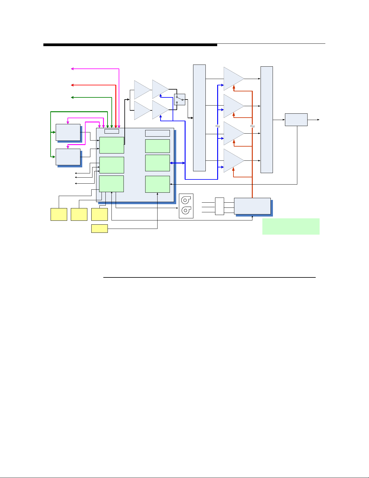
1.2.2 System Block Diagram
Figure 1-3 on page 1-5 contains a system block diagram showing the basic signal flow
and configuration for a Model ULX-12300AT Maxiva ATSC transmitter. The block
diagram shows the 12.3 kW single cabinet, liquid cooled system with 2 pre-amp
modules, 2 driver modules and 16 PA modules. Note that the predriver and driver
modules are redundant.
1-4 888-2715-001 2/19/10
WARNING: Disconnect primary power prior to servicing.
Maxiva ULX ATSC Series
User Manual
Web
Remote /
Monitoring
TO OTHER
CABINETS
TO N+1
CONTROLLER
Exciter CAN Bus
Ethernet
EX 1
EX 2
TO PUMP MODULE
INTERLOCKS
PARALLEL
CONTROL
CABINET
LEAK
DETECTOR
FLOW
METER
Ethernet
System /CAN Bus
N+1 CAN Bus
Ethernet
INLET /
OUTLET
TEMP
I/O PANEL
CAN Bus
RF
SWITCH
PUMP CONTROL
INTERLOCKS
PARALLEL
REMOTE
PS AND
COOLING
MONITOR
Pre-Drivers
TCU
Driver-PAs
Front Panel
Buttons
GUI
PA
INTERFACE
RF
MONITORING
FANS
÷
PA Bus
L1
L2
L3
16 PA’s
AC
Distribution Bus
MOV/AC
SAMPLING
Section 1 Introduction
Ȉ
DIR
COUPLER
Transmitter
Main Cabinet
Figure 1-3 Maxiva ULX-12300AT ATSC Block Diagram
1.2.3 Transmitter Control System
The Maxiva ATSC transmitter uses a simplified control system that minimizes the
number of microprocessors. Each transmitter sub-system is responsible for its own
monitoring and protection and simply reports back to the TCU (transmitter control unit)
for display on the GUI (Graphical User Interface) or to a remote interface. In multicabinet systems the TCU in cabinet 1 functions as the main controller while the TCU in
each amplifier cabinet acts as a slave controller. The cabinet 1 TCU will contain the
GUI display for the transmitter. Additional PA cabinets do not contain GUI screens.
The system bus originates in MCM (master controller module) inside the cabinet 1 TCU
and goes to the TCU located in each amplifier cabinet. The system bus is used to
transfer telemetry information in between the TCU’s.
The cabinet bus is similar to the system bus but it connects the cabinet TCU (MCM
card) to all of the nodes inside each individual cabinet. If system bus communications
with the master TCU (in cabinet 1) are interrupted the cabinet bus allows each cabinet
to operate independently.
2/19/10 888-2715-001 1-5
WARNING: Disconnect primary power prior to servicing.

Maxiva ULX ATSC Series
Section 1 Introduction
The heart of the control system is the TCU which is responsible for control, monitoring
and protection. The TCU contains the MCM (master controller module) which controls
all critical transmitter functions and the PCM (processor control module) which
provides enhanced monitoring and control, exciter and cabinet data collection, fault
logs and web remote connectivity . In addition to the MCM and PCM the Maxiva ATSC
main TCU contains six modular cards for the following sub-systems:
• PA Interface -Provides interface between TCU, IPA (driver) and PA backplane
boards. The interface features 40 digital outputs/inputs and 24 ATSC outputs and
inputs. A fully populated cabinet will require two PA interface cards, one card per
eight PA modules. The PA interface card sends the ON/OFF commands to the PA
modules and receives fault information and status from them.
• RF Detector/Pump Control/ Interlocks - Consists of a main board and a daughter
card. It features 7 RMS detectors with adjustable trip points (via EPOTS). It has
pump control and interlocks on one D25 pin connector.
• Customer I/O - Provides parallel remote control, status and meter outputs. Connector
A has all inputs and Connector B has all outputs.
• Exciter Switch - Contains PWB relay, 2 RMS detectors with adjustable trips (via
EPOTs) for power monitoring and a control/status interface for Exciters A and B.
User Manual
• PS Monitor - Monitors AC lines for phase imbalance and high or low voltage, cool-
ant inlet/outlet temperature, coolant flow, leaks, combiner temperature and cabinet
fans.
TCU’s also contain the following components:
• Base-Plane - provides a common bus for custom plug-in cards
• Power Supply Modules - two redundant internal power supply modules.
• Standard Master Control Module (MCM) - FPGA based controller used for all criti-
cal transmitter control functions.
• LED’s - standard front LED mimic display panel.
• Processor Control Module (PCM) - Coldfire based micro module running embedded
Linux OS. It provides a touch screen for enhanced monitoring and control, exciter
and multi-cabinet data collection, fault logs and web remote connectivity.
• Graphical User Interface (GUI) front panel - 5.25" color 1/4 VGA touch screen that
is present only in the main TCU (cabinet 1 in multi cabinet systems).
In multi-cabinet systems, there is a TCU in every cabinet. Each TCU will always
contain an MCM but PA cabinet TCU’s don’t require all TCU cards. The TCU in the
first PA cabinet will assume the role of master controller for the system. The TCU’s in
the remaining PA cabinets will be slaves.
1-6 888-2715-001 2/19/10
WARNING: Disconnect primary power prior to servicing.
Maxiva ULX ATSC Series
User Manual
1.2.4 Transmitter RF Power Control
The PA modules operate in open loop mode (no gain or level adjustment). The
transmitter RF power control is done via the Phase and Gain Board located in the
predriver modules. The predrivers are the only components in the drive chain (besides
the exciter) capable of adjusting their RF power based on commands from the TCU.
Each cabinet can also be placed in the "Manual Power Control Mode". In this mode the
automatic level control is disabled.
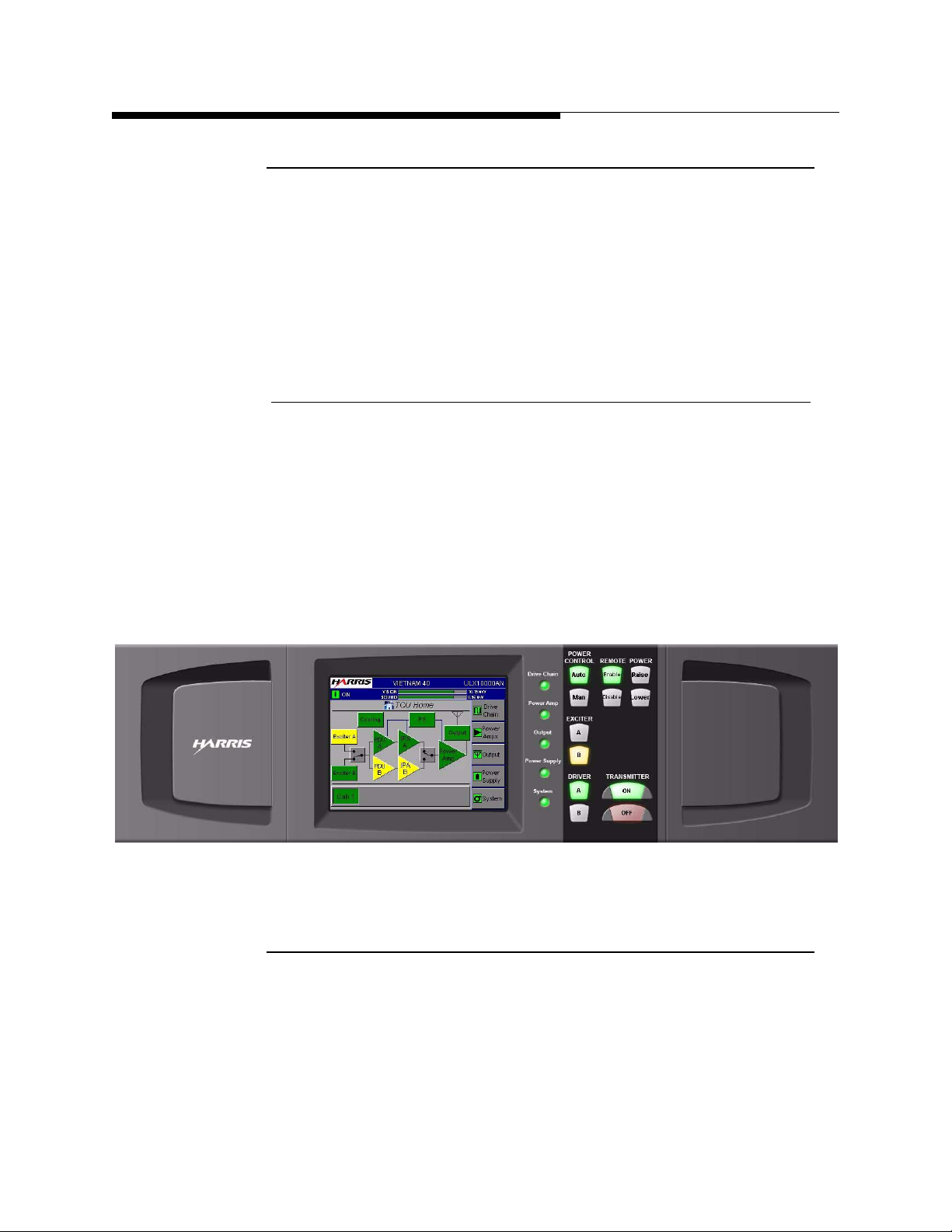
1.2.4.1 Graphical User Interface
The TCU front panel (in the control PA cabinet on multi-cabinet transmitters) contains
the graphical user interface which is a 5.25" 1/4 VGA, LCD touchscreen display. The
touchscreen display uses software buttons to monitor and control the transmitter.
Hardware buttons for the primary transmitter functions such as ON, OFF, RAISE and
LOWER are provided on the overlay panel next to the display.
Section 1 Introduction
TCU’s in additional PA cabinets will not be equipped with GUI screens.
Figure 1-4 TCU Front Control Panel
1.2.5 Control System Communications
The control system uses a serial communications system called a CAN bus. CAN stands
for Controller Area Network. The CAN bus is a closed loop serial network controlled
by the main TCU. The CAN bus connects the main TCU with TCU’s in other cabinets.
Each TCU board connected to the CAN bus is considered a node and therefore has a
specific address. This allows the master TCU to use the system bus to gather
information from all parts of the transmitter and display it on the GUI. One big
2/19/10 888-2715-001 1-7
WARNING: Disconnect primary power prior to servicing.

Maxiva ULX ATSC Series
Section 1 Introduction
advantage of the CAN bus is that it requires only 2 wires of the system control bus
ribbon cable, eliminating a large amount of discrete wiring which would otherwise be
required.
The system bus ties TCU’ s in each cabinet together. The cabinet bus is for the most part
a duplicate of the system bus but intended to connect nodes within each individual
cabinet. The cabinet bus originates in the MCM module within each TCU. The cabinet
bus is designed to keep the PA cabinets operating even if the communications with the
master cabinet TCU is lost.
1.2.5.1 Software Updates
The use of the CAN bus for communication between the various Micro Modules in the
transmitter also allows updating of the software used in each transmitter sub-system via
a serial port connection to an external computer.
NOTE:
Software does not need to be loaded into the transmitter unless new components
are installed or an update is sent from Harris. The transmitter, as shipped from the
factory, is preloaded and ready to run.
User Manual
1.2.5.2 Remote Control
The Maxiva Series ATSC transmitter has the basic discrete wired parallel remote
control with the standard connections for control, status and analog monitoring located
on the customer I/O card inside the main TCU(cabinet 1).
Maxiva transmitters include Web enabled remote GUI interface that provides
comprehensive remote control and monitoring of data points within the transmitter. It
includes an SNMP (Simple Network Management Protocol) manager which allows
integration with most Control Systems via the Internet or LAN.
1.2.6 PA Module
The Maxiva ULX Series PA Module utilizes LDMOS (laterally diffused metal oxide
semi-conductor) amplifiers to produce up to 800 W average power output. Each module
weighs approximately 22kg and can be removed while the transmitter is running. A
single cabinet Maxiva Series transmitter can have 2, 3, 4, 6, 8, 10, 12, or 16 PA modules
to achieve the various power levels shown in
diagram of the PA module is shown in Figure 1-5 on page 1-9.
Table 1-1 page1-4. A simplified block
1-8 888-2715-001 2/19/10
WARNING: Disconnect primary power prior to servicing.
Maxiva ULX ATSC Series
User Manual
The amplifier and driver modules are interchangeable and do not contain
microcontrollers but instead use a CPLD based monitor board in each PA to report
faults to the TCU and to take appropriate self-protective action if needed.
Section 1 Introduction
Figure 1-5 PA Module Simplified Block Diagram
2/19/10 888-2715-001 1-9
WARNING: Disconnect primary power prior to servicing.
Maxiva ULX ATSC Series
Section 1 Introduction
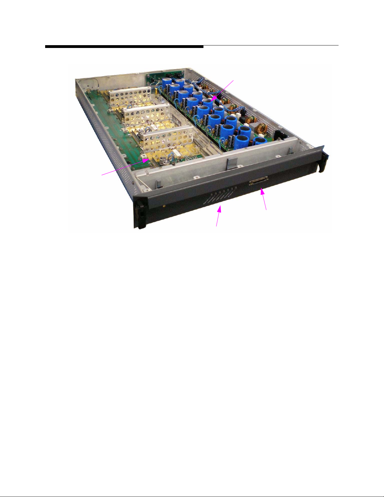
4 RF Pallets
User Manual
8 AC-DC Converter Modules
Diagnostic Port
Status LED’s
Figure 1-6 Maxiva PA Module (cover removed)
The diagnostic port shown in Figure 1-6 allows the operator to connect directly to the
PA module with a handheld device and obtain PS voltages, fault status, FWD and REF
RF power levels and internal temperatures. The diagnostic port can also be used to
reprogram the CPLD as required.
1-10 888-2715-001 2/19/10
WARNING: Disconnect primary power prior to servicing.
 Loading...