

GatesAir UAXDVF User Manual

888-271 1-001
Maxiva UAX Transmitter
Outdoor Enclosure System
User Manual
Maxiva UAX Transmitter
Outdoor Enclosur e System
T.M. No. 888-2711-001
© Copyright Harris Corporation 2010
All rights reserved
Feb. 9, 2010
Rev: A

ii 888-2711-001 2/9/10
WARNING: Disconnect primary power prior to servicing.

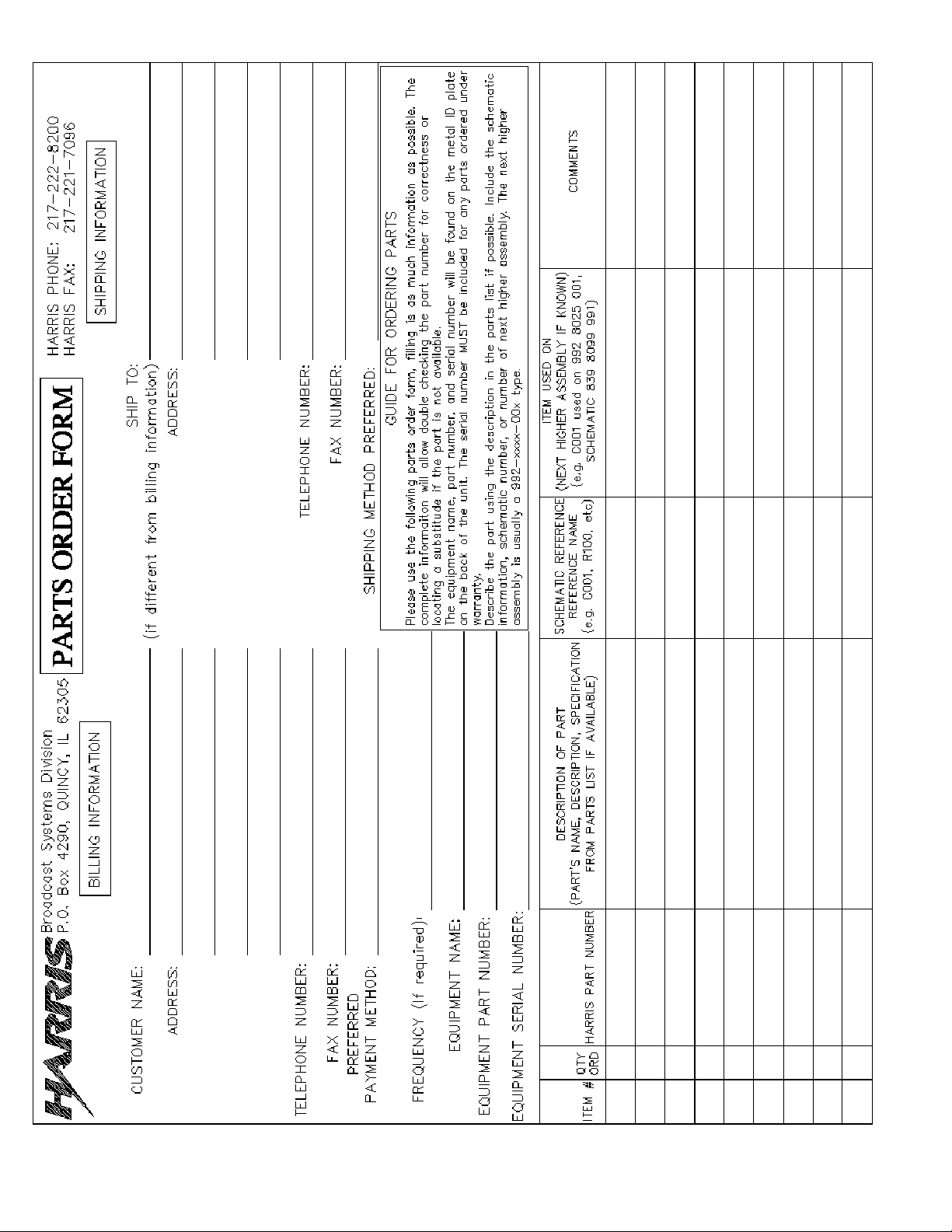
Technical Assistance
Technical and troubleshooting assistance for HARRIS Transmission products is available from
HARRIS Field Service (factory location: Quincy, Illinois, USA) during normal business hours
(8:00 AM - 5:00 PM Central Time). Telephone +1-217-222-8200 to contact the Field Service
Department; FAX +1-217-221-7086; or E-mail questions to tsupport@harris.com.
Emergency service is available 24 hours a day, seven days a week, by telephone only.
On-line assistance, including technical manuals, white papers, software downloads, and service
bulletins, is available at http://support.broadcast.harris.com/eservice_enu.
Address written correspondence to Field Service Department, HARRIS Broadcast
Communications Division, P.O. Box 4290, Quincy, Illinois 62305-4290, USA. For other global
service contact information, please visit: http://www.broadcast.harris.com/contact.
NOTE: For all service and parts correspondence, you will need to provide the Sales Order
number, as well as the Serial Number for the transmitter or part in question. For future reference,
record those numbers here: ___________________/____________________
Please provide these numbers for any written request, or have these numbers ready in the event
you choose to call regarding any Service, or Parts requests. For warranty claims it will be required,
and for out of warranty products, this will help us to best identify what specific hardware was
shipped.
Replaceable Parts Service
Replacement parts are available from HARRIS Service Parts Department from 7:00 AM to 11:00
PM Central Time, seven days a week. Telephone +1-217-222-8200 or email
servicepartsreq@harris.com to contact the Service Parts Department.
Emergency replacement parts are available by telephone only, 24 hours a day, seven days a
week by calling +1-217-222-8200.
Unpacking
Carefully unpack the equipment and preform a visual inspection to determine if any apparent
damage was incurred during shipment. Retain the shipping materials until it has been verified that
all equipment has been received undamaged. Locate and retain all PACKING CHECK LISTs. Use
the PACKING CHECK LIST to help locate and identify any components or assemblies which are
removed for shipping and must be reinstalled. Also remove any shipping supports, straps, and
packing materials prior to initial turn on.
Returns And Exchanges
No equipment can be returned unless written approval and a Return Authorization is received from
HARRIS Broadcast Communications Division. Special shipping instructions and coding will be
provided to assure proper handling. Complete details regarding circumstances and reasons for
return are to be included in the request for return. Custom equipment or special order equipment is
not returnable. In those instances where return or exchange of equipment is at the request of the
customer, or convenience of the customer, a restocking fee will be charged. All returns will be sent
freight prepaid and properly insured by the customer. When communicating with HARRIS
Broadcast Communications Division, specify the HARRIS Order Number or Invoice Number.
2/9/10 888-2711-001 iii
WARNING: Disconnect primary power prior to servicing.

iv 888-2711-001 2/9/10
WARNING: Disconnect primary power prior to servicing.

Manual Revision History
Maxiva UAX Transmitter Outdoor Enclosure System Manual
REV. DATE ECN Pages Affected / Description
2010 FEB Create manual.
2/9/10 888-2711-001 MRH-1
WARNING: Disconnect primary power prior to servicing.

MRH-2 888-2711-001 2/9/10
WARNING: Disconnect primary power prior to servicing.
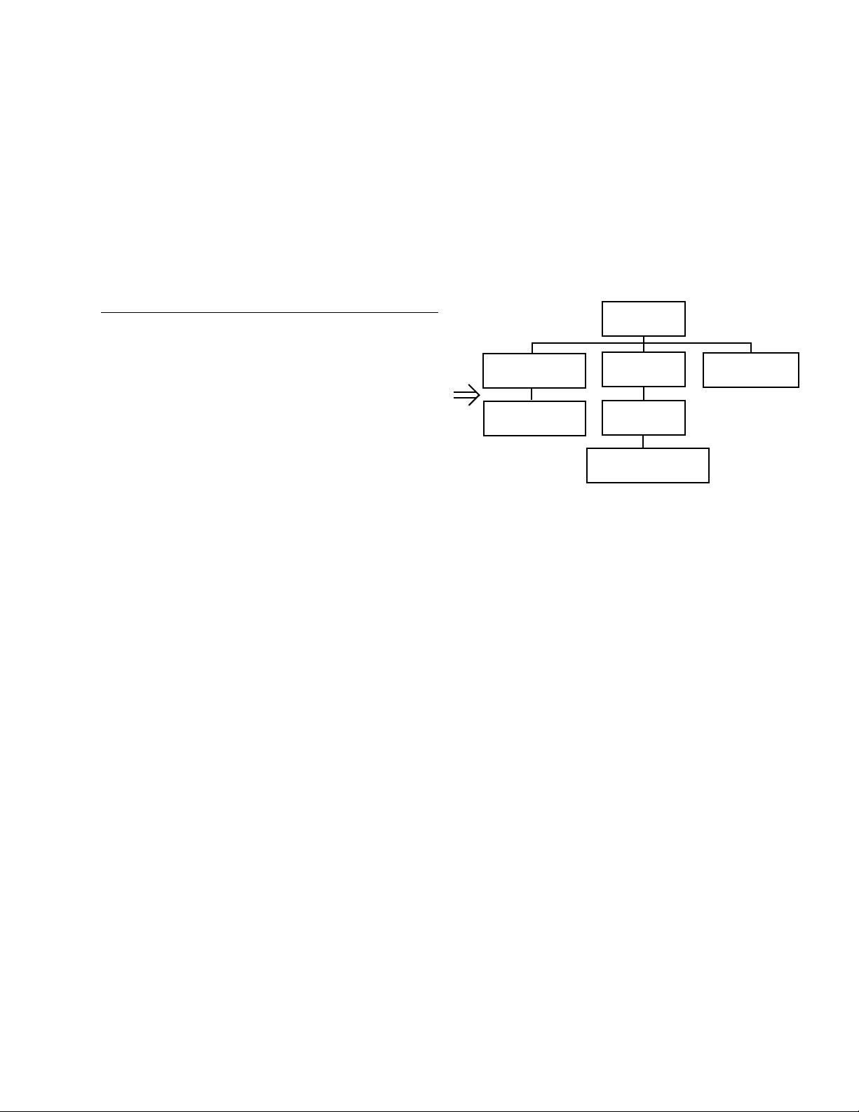
Guide to Using Harris Parts List Information
The Harris Replaceable Parts List Index portrays a tree structure with the major items being leftmost in the index.
The example below shows the Transmitter as the highest item in the tree structure. If you were to look at the bill
of materials table for the Transmitter you would find the Control Cabinet, the PA Cabinet, and the Output
Cabinet. In the Replaceable Parts List Index the Control Cabinet, PA Cabinet, and Output Cabinet show up one
indentation level below the Transmitter and implies that they are used in the Transmitter. The Controller Board is
indented one level below the Control Cabinet so it will show up in the bill of material for the Control Cabinet.
The tree structure of this same index is shown to the right of the table and shows indentation level versus tree
structure level.
Example of Replaceable Parts List Index and equivalent tree structure:
Replaceable Parts List Index Part Number Page
Table 7-1. Transmitter 994 9283 001 7-2
Table 7-2. Control Cabinet 992 9244 002 7-3
Table 7-3. Controller Board 992 8344 002 7-6
Table 7-4. PA Cabinet 992 9400 002 7-7
Table 7-5. PA Amplifier 994 7894 002 7-9
Table 7-6. PA Amplifier Board 992 7904 002 7-10
Table 7-7. Output Cabinet 992 9450 001 7-12
The part number of the item is shown to the right of the description as is the page in the manual where the bill for
that part number starts. Inside the actual tables, four main headings are used:
Control Cabinet
992 9244 002
Controller Board
992 8344 002
Transmitter
994 9283 001
PA Cabinet
992 9400 002
PA Amplifier
992 7894 002
PA Amplifier Board
992 7904 002
Output Cabinet
992 9450 001
• Table #-#. ITEM NAME - HARRIS PART NUMBER - this line gives the information that corresponds
to the
• Replaceable Parts List Index entry;
• HARRIS P/N column gives the ten digit Harris part number (usually in ascending order);
• DESCRIPTION column gives a 25 character or less description of the part number;
• REF. SYMBOLS/EXPLANATIONS column 1) gives the reference designators for the item (i.e., C001,
R102, etc.) that corresponds to the number found in the schematics (C001 in a bill of material is equiva
lent to C1 on the schematic) or 2) gives added information or further explanation (i.e., “Used for 208V
operation only,” or “Used for HT 10LS only,” etc.).
-
NOTE: Inside the individual tables some standard conventions are used:
• A # symbol in front of a component such as #C001 under the REF. SYMBOLS/EXPLANATIONS col-
umn means that this item is used on or with C001 and is not the actual part number fo r C001.
• In the ten digit part numbers, if the last three numbers are 000, the item is a part that Harris has pur-
chased and has not manufactured or modified. If the last three numbers are other than 000, the item is
either manufactured by Harris or is purchased from a vendor and modified for use in the Harris product.
• The first three digits of the ten digit part number tell which family the part num ber belongs to - for
example, all electrolytic (can) capacitors will be in the same family (524 xxxx 000). If an electrolytic
(can) capacitor is found to have a 9xx xxxx xxx part number (a number outside of the normal family of
numbers), it has probably been modified in some manner at the Harris factory and will therefore show
up farther down into the individual parts list (because each table is normally sorted in ascending order).
Most Harris made or modified assemblies will have 9xx xxxx xxx numbers associated with them.
The term “SEE HIGHER LEVEL BILL” in the description column implies that the reference designated part
number will show up in a bill that is higher in the tree structure. This is often the case for components
that may be frequency determinant or voltage determinant and are called out in a higher level bill
structure that is more customer dependent than the bill at a lower level.
2/9/10 888-2711-001 vii
WARNING: Disconnect primary power prior to servicing.

viii 888-2711-001 2/9/10
WARNING: Disconnect primary power prior to servicing.
2/9/10 888-2711-001 ix
WARNING: Disconnect primary power prior to servicing.

x 888-2711-001 2/9/10
WARNING: Disconnect primary power prior to servicing.

!
WA RN IN G:
THE CURRENTS AND VOLTAGES IN THIS EQUIPMENT ARE DANGEROUS.
PERSONNEL MUST AT ALL TIMES OBSERVE SAFETY WARNINGS, INSTRUC
TIONS AND REGULATIONS.
-
This manual is intended as a general guide for trained and qualified personnel who are aware
of the dangers inherent in handling potentially hazardous electrical/electronic circuits. It is not
intended to contain a complete statement of all safety precautions which should be observed
by personnel in using this or other electronic equipment.
The installation, operation, maintenance and service of this equipment involves risks both to
personnel and equipment, and must be performed only by qualified personnel exercising due
care. HARRIS CORPORATION shall not be responsible for injury or damage resulting from
improper procedures or from the use of improperly trained or inexperienced personnel
performing such tasks. During installation and operation of this equipment, local building
codes and fire protection standards must be observed.
The following National Fire Protection Association (NFPA) standards are recommended as
reference:
- Automatic Fire Detectors, No. 72E
- Installation, Maintenance, and Use of Portable Fire Extinguishers, No. 10
- Halogenated Fire Extinguishing Agent Systems, No. 12A
!
WA RN IN G:
ALWAYS DISCONNECT POWER BEFORE OPENING COVERS, DOORS, ENCLOSURES, GATES, PANELS OR SHIELDS. ALWAYS USE GROUNDING STICKS
AND SHORT OUT HIGH VOLTAGE POINTS BEFORE SERVICING. NEVER MAKE
INTERNAL ADJUSTMENTS, PERFORM MAINTENANCE OR SERVICE WHEN
ALONE OR WHEN FATIGUED.
Do not remove, short-circuit or tamper with interlock switches on access covers, doors,
enclosures, gates, panels or shields. Keep away from live circuits, know your equipment and
don’t take chances.
!
WA RN IN G:
IN CASE OF EMERGENCY ENSURE THA T POWER HAS BEEN DISCONNECTED.
IF OIL FILLED OR ELECTROLYTIC CAPACITORS ARE UTILIZED IN YOUR
EQUIPMENT, AND IF A LEAK OR BULGE IS APPARENT ON THE CAPACITOR CASE
WHEN THE UNIT IS OPENED FOR SERVICE OR MAINTENANCE, ALLOW THE UNIT
TO COOL DOWN BEFORE ATTEMPTING TO REMOVE THE DEFECTIVE CAPACITOR.
DO NOT A T TEMP T T O SERVICE A DEFECTIVE CAPACIT OR WHILE IT IS HOT DUE T O
THE POSSIBILITY OF A CASE RUPTURE AND SUBSEQUENT INJURY.
2/9/10 888-2711-001 xi
WARNING: Disconnect primary power prior to servicing.
xii 888-2711-001 2/9/10
WARNING: Disconnect primary power prior to servicing.

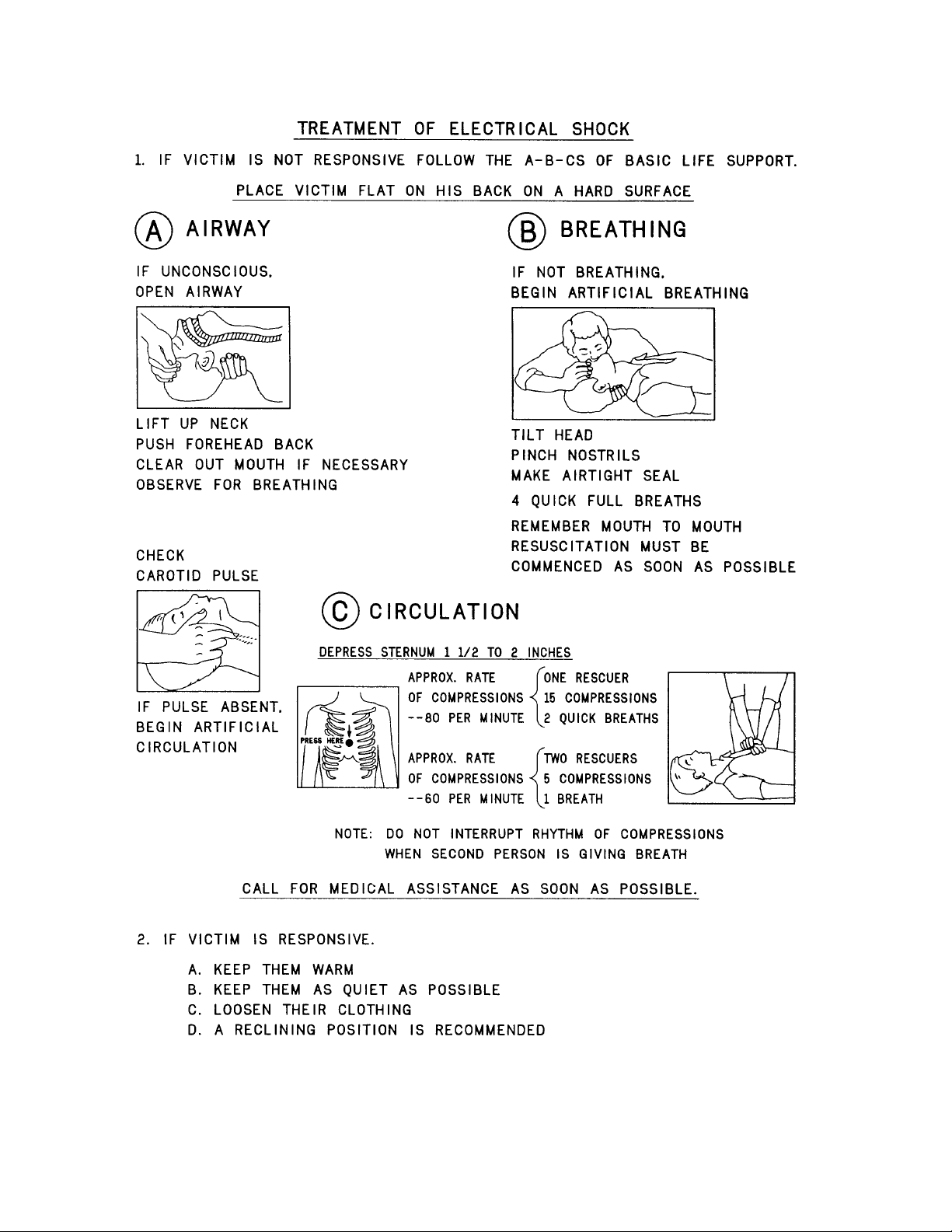
FIRST-AID
Personnel engaged in the installation, operation, maintenance or servicing of this equipment
are urged to become familiar with first-aid theory and practices. The following information is
not intended to be complete first-aid procedures, it is a brief and is only to be used as a
reference. It is the duty of all personnel using the equipment to be prepared to give adequate
Emergency First Aid and there by prevent avoidable loss of life.
Treatment of Electrical Burns
1. Extensive burned and broken skin
a. Cover area with clean sheet or cloth. (Cleanest available cloth
article.)
b. Do not break blisters, remove tissue, remove adhered particles of
clothing, or apply any salve or ointment.
c. Treat victim for shock as required.
d. Arrange transportation to a hospital as quickly as possible.
e. If arms or legs are affected keep them elevated.
NOTE:
If medical help will not be available within an hour and the victim is conscious and
not vomiting, give him a weak solution of salt and soda: 1 level teaspoonful of salt
and 1/2 level teaspoonful of baking soda to each quart of water (neither hot or
cold). Allow victim to sip slowly about 4 ounces (a half of glass) over a period of
15 minutes. Discontinue fluid if vomiting occurs. (Do not give alcohol.)
2. Less severe burns - (1st & 2nd degree)
a. Apply cool (not ice cold) compresses using the cleanest available
cloth article.
b. Do not break blisters, remove tissue, remove adhered particles of
clothing, or apply salve or ointment.
c. Apply clean dry dressing if necessary.
d. Treat victim for shock as required.
e. Arrange transportation to a hospital as quickly as possible.
f. If arms or legs are affected keep them elevated.
REFERENCE:
ILLINOIS HEART ASSOCIATION
AMERICAN RED CROSS ST ANDARD FIRST AID AND PERSONAL SAFETY
MANUAL (SECOND EDITION)
2/9/10 888-2711-001 xiii
WARNING: Disconnect primary power prior to servicing.

Glossary:
ASI - Asynchronous serial interface
BPF- Band pass filter. May also be called a mask filter, or critical mask filer.
CAN - Controller–area network (CAN or CAN-bus) is a vehicle bus standard
designed to allow microcontrollers and devices to communicate with each other
DAC - digital analog converter
FPGA - Field programmable gate array
GUI - graphical user interface
Hot-pluggable - device can be removed while transmitter is operating.
HTML - HyperText Markup Language
IRD - Integrated receiver decoder
LCD - Liquid crystal display
LPF - Low pass filter. Typically located at the transmitter output port. Used to
attenuate out of band emissions.
LPU - Low power unit. Contains modulator and amplifier sections.
MCM - Master control module (card in TCU)
PA - Power amplifier
PAB - Power amplifier block
PCM - Processor control module (card in TCU)
PS - Power supply
RF - Radio frequency
RS-485 -TIA/EIA standard for serial multipoint communications lines
RTACTM - Real time adaptive correction
xiv 888-2711-001 2/9/10
WARNING: Disconnect primary power prior to servicing.

Glossary Continued:
SFN - Single frequency network
SMA - SMA connector consists of a 0.250x36 thread. The male is equipped with a
.312 inch (7.925mm) hex nut
TCU - Transmitter control unit.
UDC - Up-down converter
UPS - Uninterruptable power supply
VGA - Video graphics array
WEB - A system of Internet servers that support HTML formatted documents.
2/9/10 888-2711-001 xv
WARNING: Disconnect primary power prior to servicing.

xvi 888-2711-001 2/9/10
WARNING: Disconnect primary power prior to servicing.

Table of Contents
Section 1
Introduction
Purpose of This Manual . . . . . . . . . . . . . . . . . . . . 1-1
General Description. . . . . . . . . . . . . . . . . . . . . . . . 1-3
System Block Diagrams . . . . . . . . . . . . . . . . . . . 1-11
System Specifications . . . . . . . . . . . . . . . . . . . . . 1-12
Environmental and Physical. . . . . . . . . . . . . . . 1-12
AC power . . . . . . . . . . . . . . . . . . . . . . . . . . . . . 1-12
Connectors . . . . . . . . . . . . . . . . . . . . . . . . . . . . 1-12
Section 2
Installation /
Initial Turn-On
Introduction. . . . . . . . . . . . . . . . . . . . . . . . . . . . . . 2-1
Documentation . . . . . . . . . . . . . . . . . . . . . . . . . . . 2-1
UAX Enclosure System Drawings. . . . . . . . . . . 2-2
Cabinet Placement. . . . . . . . . . . . . . . . . . . . . . . . . 2-2
Cabinet Attachments. . . . . . . . . . . . . . . . . . . . . . . 2-4
Installation of Components Removed for Shipment2- 6
Install PA Modules . . . . . . . . . . . . . . . . . . . . . . . 2-7
AC/Ground connections . . . . . . . . . . . . . . . . . . . . 2-9
Ground connections. . . . . . . . . . . . . . . . . . . . . . . 2-10
Transmitter RF output connection. . . . . . . . . . . . 2-12
Signal Connections . . . . . . . . . . . . . . . . . . . . . . . 2-14
Customer Remote Control & Interlock
Connections. . . . . . . . . . . . . . . . . . . . . . . . . . . . . 2-15
Customer Remote Control & Interlock
Connections. . . . . . . . . . . . . . . . . . . . . . . . . . . . . 2-16
Initial Turn-On . . . . . . . . . . . . . . . . . . . . . . . . . . 2-16
Section 3
Operation & Maintenance
Introduction. . . . . . . . . . . . . . . . . . . . . . . . . . . . . . 3-1
Transmitter Control Unit (TCU). . . . . . . . . . . . . . 3-1
Control Buttons overview: . . . . . . . . . . . . . . . . . 3-2
Maintenance . . . . . . . . . . . . . . . . . . . . . . . . . . . . . 3-4
Section 4
Parts List
Replaceable Parts List. . . . . . . . . . . . . . . . . . . . . . 4-1
1

Table of Contents
2

Maxiva UAX Transmitter Outdoor Enclosure System
User Manual
Section 1 Introduction
1.1 Purpose of This Manual
This User manual describes the UAX Outdoor Enclosure System utilizing the UAX
Maxiva transmitter. The contents of this manual address the location of system
components of the enclosure system, installation hook-up requirements, initial turn-on
steps, and overall system operation. Detailed information pertaining to the UAX
Maxiva Transmitter is not included here, but can be found in a separate doc package
(988-2693-001) included with the transmitter. Detailed information regarding
individual system components can be found in the component documentation material
supplied with this enclosure system. The various sections of this User manual provide
the following types of information.
1
Section 1, Introduction, provides equipment location information, block diagram and
general specifications.
Section 2, Installation/Initial Turn-On, provides cabinet hardware and electrical
installation information for the transmitter enclosure system including: Cabinet
placement, solar shield, GPS antenna, AC Power connection, RF system connections,
customer input connections, and remote interface connections.
Section 3, Operation, provides general operation information for the enclosure system.
Specific equipment operation information can be found in the technical manuals/
pamphlets provided by the manufactures of the various components included in the
enclosure system. Most of these can be found in a pouch inside the back door of the
enclosure.
Section 4, Parts List, provides a list of parts used in a typical UAX enclosure system.
2/9/10 888-2711-001 1-1
WARNING: Disconnect primary power prior to servicing.
Maxiva UAX Transmitter Outdoor Enclosure System
Section 1 Introduction
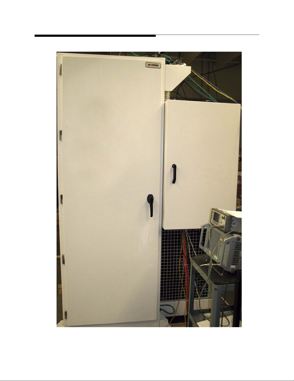
Main Equipment
Cabinet
User Manual
AC Distribution
Box
Figure 1-1 UAX Outdoor Enclosure System - Front Doors
1-2 888-2711-001 2/9/10
WARNING: Disconnect primary power prior to servicing.
 Loading...