

Gatekeeper Systems Fleet Safety, Security and Tracking Solutions G4-304SD1, G4-304SD1a User Manual & Installation Manual

G4-304SD1
User Manual & Install Guide
Document Ref. No. : DN2882
Version No. : 1.0.1
Document Date : 29th August 2016
Fleet Safety, Security and Tracking Solutions TM

G4-304SD1 User Manual & Install Guide
Table of Contents
2 of 149
TABLE OF CONTENTS
GLOSSARY ............................................................................................................................................ 5
1 INTRODUCTION ........................................................................................................................... 7
1.1 WELCOME TO YOUR NEW G4-304SD1 .................................................................................................................... 7
1.2 IMPORTANT SAFETY AND HANDLING INFORMATION ................................................................................................ 7
2 YOUR G4-304SD1 AT A GLANCE ................................................................................................. 9
2.1 TAKE A TOUR ................................................................................................................................................................. 9
2.2 WHAT’S INCLUDED .................................................................................................................................................... 11
3 GETTING STARTED ..................................................................................................................... 13
3.1 LEARNING HOW TO NAVIGATE ................................................................................................................................. 13
3.1.1 Using the IR Remote Control .................................................................................................................... 14
3.1.2 Using the Trackball Mouse....................................................................................................................... 16
3.1.3 Using the Interactive Control Display (ICD2) ...................................................................................... 18
3.2 GUIDE TO COMMON NAVIGATION ACTIONS .......................................................................................................... 20
3.3 THE G4-304SD1 STARTUP SCREEN LAYOUT ......................................................................................................... 23
3.4 VIEWING LIVE VIDEO ................................................................................................................................................. 24
3.5 QUICK VIEW OF SYSTEM STATUS INFORMATION .................................................................................................... 26
3.6 LOGGING INTO THE SYSTEM...................................................................................................................................... 29
3.7 UNDERSTANDING THE MAIN MENU ........................................................................................................................ 31
4 BASIC SYSTEM QUICK START .................................................................................................... 33
4.1 STEP 1: POWERING UP THE G4-304SD1 ............................................................................................................... 33
4.2 STEP 2: CONNECTING YOUR NAVIGATION DEVICE ................................................................................................. 33
4.3 STEP 3: LOGGING IN AND ACCESSING SYSTEM CONFIGURATION ......................................................................... 34
4.4 STEP 4: SETTING THE DATE AND TIME ..................................................................................................................... 37
4.5 STEP 5: SETTING THE VEHICLE IDENTITY INFORMATION ......................................................................................... 38
4.6 STEP 6: SETTING BASIC PREFERENCES ...................................................................................................................... 39
4.7 STEP 7: SETTING UP AUTHORISED USERS ............................................................................................................... 40
4.8 STEP 8: SETTING UP RECORDING ............................................................................................................................. 41
4.9 STEP 9: SETTING UP IP CAMERAS ............................................................................................................................ 43
4.10 STEP 10: FINISH ......................................................................................................................................................... 44
5 VIEWING RECORDED DATA ....................................................................................................... 45
5.1 USING THE PLAYBACK FEATURE ................................................................................................................................ 45
5.2 USING REC SEARCH .................................................................................................................................................. 48
5.3 USING LOG SEARCH .................................................................................................................................................. 56
6 CONFIGURING THE G4-304SD1 ................................................................................................ 60
6.1 QUICK REFERENCE TO CONFIGURATION MENU SYSTEM ....................................................................................... 60
6.2 NAVIGATING THE CONFIGURATION MENUS ........................................................................................................... 61
6.3 BASIC SETTINGS ......................................................................................................................................................... 64
6.3.1 Regist Info ....................................................................................................................................................... 65
6.3.2 Time Setup ...................................................................................................................................................... 67
6.3.3 Startup ............................................................................................................................................................. 71

G4-304SD1 User Manual & Install Guide
Table of Contents
3 of 149
6.3.4 User Setup ....................................................................................................................................................... 74
6.3.5 Network ........................................................................................................................................................... 76
6.3.6 Application ..................................................................................................................................................... 83
6.4 SURVEILLANCE SETTINGS ........................................................................................................................................... 84
6.4.1 Live View ......................................................................................................................................................... 85
6.4.2 Record .............................................................................................................................................................. 91
6.4.3 IPC Setup ....................................................................................................................................................... 102
6.5 COLLECTION SETTINGS ............................................................................................................................................ 105
6.5.1 General .......................................................................................................................................................... 105
6.5.2 Snap Setting ................................................................................................................................................. 109
ALARM SETTINGS ................................................................................................................................................................... 113
6.5.3 Base ................................................................................................................................................................ 113
6.5.4 Driver Alert Button: Setup ....................................................................................................................... 121
6.5.5 Video .............................................................................................................................................................. 121
6.5.6 Advanced ...................................................................................................................................................... 123
6.6 MAINTENANCE SETTINGS ........................................................................................................................................ 126
6.6.1 Config ............................................................................................................................................................. 126
6.6.2 Filedata .......................................................................................................................................................... 127
6.6.3 Upgrade ......................................................................................................................................................... 128
6.6.4 Storage ........................................................................................................................................................... 128
6.6.5 Reset ............................................................................................................................................................... 129
7 SPECIAL TOPICS........................................................................................................................ 130
7.1 SETTING UP AN IP CAMERA ................................................................................................................................... 130
7.1.1 Adding an IP Camera ............................................................................................................................... 130
7.2 CONFIGURING SUBSTREAM RECORDING QUALITY ............................................................................................... 131
7.3 USING A NEW SD CARD ......................................................................................................................................... 134
7.4 SEQUENTIAL RECORDING (REQUIRES TWO SD CARDS). ...................................................................................... 135
7.5 UPGRADING DEVICE FIRMWARE ............................................................................................................................. 136
8 MAINTENANCE AND TROUBLESHOOTING ............................................................................ 137
9 HARDWARE INSTALLATION .................................................................................................... 138
9.1 QUICK REFERENCE GUIDE FOR INSTALLATION....................................................................................................... 138
9.2 INSTRUCTIONS FOR MOUNTING THE SYSTEM ....................................................................................................... 140
9.3 DETAILED CABLING DIAGRAMS .............................................................................................................................. 142
9.3.1 Fuse Connections ....................................................................................................................................... 142
9.3.2 Cabling Diagrams ...................................................................................................................................... 142
9.4 CAMERA MOUNTING AND CONNECTIONS ............................................................................................................ 145
10 CUSTOMER LIMITED WARRANTY ....................................................................................... 148
11 CONTACT INFORMATION. ................................................................................................... 149

G4-304SD1 User Manual & Install Guide
4 of 149
TABLE OF FIGURES
Figure 2-1 Front View of the G4-304SD1.......................................................................................................................... 9
Figure 2-2 Close Up View of the G4-304SD1 Status Indicator Lights .................................................................... 9
Figure 2-3 Rear View of the G4-304SD1 ........................................................................................................................ 10
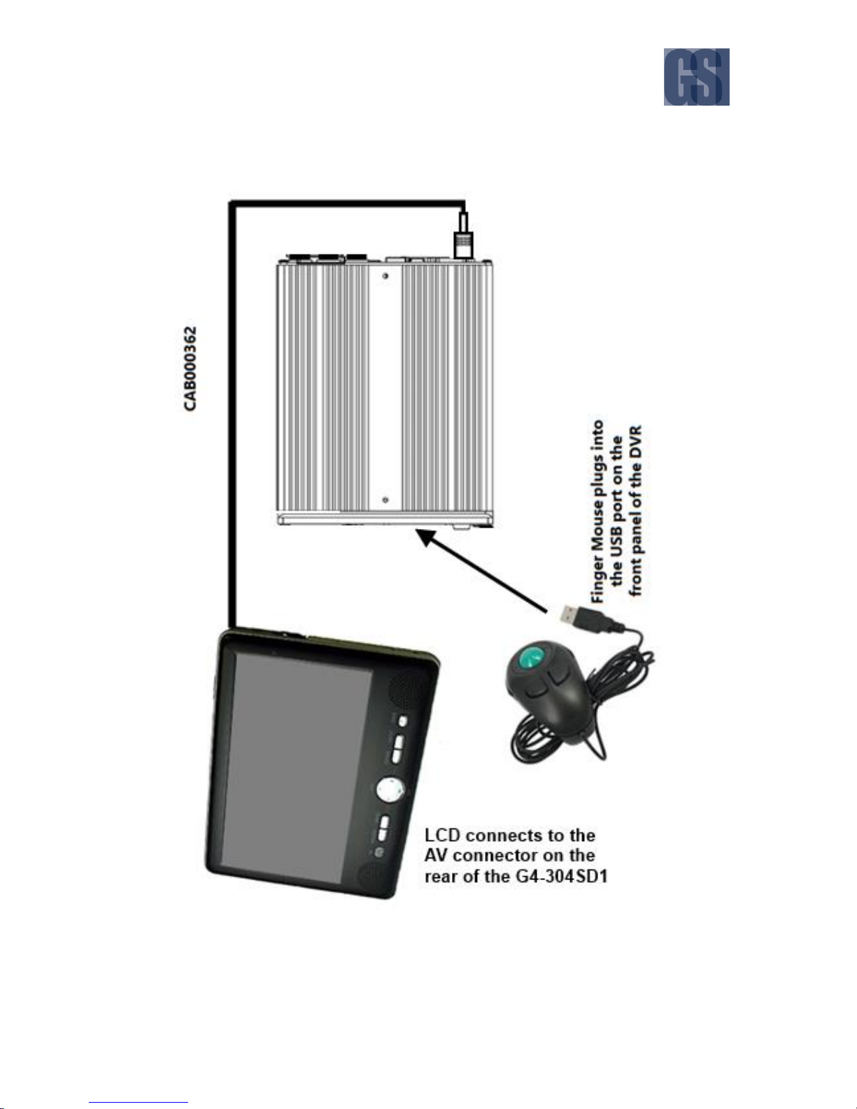
Figure 3-1 Side View of the Finger Mouse .................................................................................................................... 16
Figure 3-2 Connecting the Finger Mouse and LCD Monitor .................................................................................. 17
Figure 3-3 Front View of the ICD2 .................................................................................................................................... 18
Figure 3-4 Connecting the ICD2 ....................................................................................................................................... 19
Figure 3-5 G4-304SD1 Startup Screen ............................................................................................................................ 23
Figure 3-6 Cycling through the Video Channels in Single View ............................................................................ 24
Figure 3-7 Example of Video Loss .................................................................................................................................... 26
Figure 3-8 Accessing the Main Menu ............................................................................................................................. 31
Figure 3-9 Options in the Main Menu ............................................................................................................................ 31
Figure 4-1 Live Camera View Shown on Device Startup .......................................................................................... 33
Figure 4-2 Setup Menu System for Device Configuration ....................................................................................... 36
Figure 5-1 Accessing the Playback Feature ................................................................................................................... 45
Figure 5-2 Playback On-Screen Controls ....................................................................................................................... 46
Figure 5-3 REC Search Date Controls .............................................................................................................................. 48
Figure 5-4 REC Search Camera Channel Controls ...................................................................................................... 49
Figure 5-5 REC Search Time Controls.............................................................................................................................. 50
Figure 5-6 REC Search Playback Controls ...................................................................................................................... 52
Figure 5-7 Log Search Date Controls .............................................................................................................................. 57
Figure 5-8 Log Time and Type Selection ....................................................................................................................... 58
Figure 5-9 View and Export Log File ................................................................................................................................ 59
Figure 6-1 Layout of the Configuration Menu ............................................................................................................. 61
Figure 6-2 Basic Setup Tab in the Device Configuration Options ........................................................................ 65
Figure 6-3 Surveillance Tab in the Device Configuration Options ....................................................................... 84
Figure 6-4 4 IP Camera Setup Screen............................................................................................................................ 102
Figure 6-5 4 IP Camera Settings Configuration Screen .......................................................................................... 103
Figure 6-6 Collection Tab in the Device Configuration Options ......................................................................... 105
Figure 6-7 Alarm Tab in the Device Configuration Options ................................................................................. 113
Figure 6-8 Maintenance Tab in the Device Configuration Options ................................................................... 126
Figure 7-1 Setting Up for Substream Recording ....................................................................................................... 132
Figure 7-2 Substream Recording Settings ................................................................................................................... 132
Figure 7-3 Formatting a New Storage Medium ........................................................................................................ 134
Figure 7-4 Upgrading Device Firmware........................................................................................................................ 136
Figure 9-1 G4-304SD1 Fuse Connections .................................................................................................................... 142
Figure 9-2: Basic Analog Connection ............................................................................................................................ 142
Figure 9-3: Basic Analog + IP ........................................................................................................................................... 143
Figure 9-4: G4-304SD1 Wiring with Wireless. ........................................................................................................... 144

G4-304SD1 User Manual & Install Guide
5 of 149
GLOSSARY
Term/Abbreviation
Description
ACC
Accelerometer
CAN
Controller Area Network is a vehicle bus standard designed to allow
microcontrollers and devices to communicate with each other in
applications without a host computer.
G4-304SD1
Digital Video Recorder – a device which records audio and video input
from the cameras and stores it to a hard disk drive and/or an SD card
for retrieval and viewing.
FTP
File Transfer Protocol is a standard network protocol used to transfer
computer files from one host to another host over a TCP-based
network, such as the Internet.
GPS
Global Positioning System – it is a radio navigation system that allows
land, sea, and airborne users to determine their exact location, velocity,
and time 24 hours a day, in all weather conditions, anywhere in the
world.
H.264
Also known as MPEG-4 Part 10, Advanced Video Coding (MPEG-4
AVC), this is a video coding format that is currently one of the most
commonly used formats for the recording, compression, and
distribution of video content.
ICD / ICD2
Interactive Control Display, purpose built touch screen monitors for
operating Gatekeeper Systems G4-304SD1s.
IO
Input/Output
IP Camera
An Internet protocol camera, or IP camera, is a type of digital video
camera commonly employed for surveillance, and which, unlike analog
closed circuit television cameras, can send and receive data via a
computer network and the Internet.
LAN
Local Area Network – it is a computer network that interconnects
computing devices within a limited area such as a school, work area,
or an office building.
LCD Monitor
Liquid Crystal Display Monitor – it is a display screen that uses
electronically modulated segments controlling a layer of liquid crystals
and arrayed in front of a light source (backlight) or reflector to produce
images and text.
MAC Address
Media Access Control address – it is a unique identifier assigned to
network interfaces for communications on the physical network
segment.

G4-304SD1 User Manual & Install Guide
6 of 149
OSD
On Screen Display – an image superimposed on a screen commonly
used to display information such as volume, channel, date/time, device
status, etc. It also forms the basis of the menu system display which is
used to configure the system settings of the digital video recorder.
SD
Secure Digital Card – an ultra-small flash memory card designed to
provide high-capacity memory in a small form factor. It is a commonly
used high performance portable storage standard for video and audio
capture devices.
TCP
TCP is one of the main protocols in TCP/IP networks which enables
two hosts to establish a connection and exchange streams of data. TCP
guarantees delivery of data and also guarantees that packets will be
delivered in the same order in which they were sent.
UDP
UDP is a simple connectionless transmission model with a minimum
overhead of protocol mechanisms.
USB
Universal Serial Bus – it is an industry standard that defines the cables,
connectors and communications protocols used in a bus for
connection, communication, and power supply between computers
and electronic devices.
UTC
Coordinated Universal Time is a time standard based on International
Atomic Time with leap seconds added at irregular intervals to
compensate for the Earth’s slowing rotation. It is the primary time
standard by which the world regulates clocks and time.
G4-304SD1 User Manual & Install Guide
7 of 149
1 Introduction
1.1 Welcome to Your New G4-304SD1
Congratulations on the purchase of your new Gatekeeper Systems G4-304SD1. This Mobile Digital Video
Recorder offers H.264 compression, the same compression technique as used in Blu-Ray disk players
that produces crystal clear, best in class, video imagery.
The G4-304SD1 records to a removable SD (Secure Digital) card. Utilizing a state of the art suspension
system and smart thermal management technology, the G4-304SD1 is built to withstand the shocks,
vibration and environmental stresses inherent in vehicle operation. In order to play back the recorded
video the G4-304SD1 utilizes custom video viewing software, “G4 Viewer Plus”, an easy to use
application that allows users to quickly find the video of interest and save a clip. With the press of a
button, users can print images and then send them to authorized staff.
1.2 Important Safety and Handling Information
Before using the product, please ensure that you observe the safety precautions described below. The
safety precautions noted on the following pages are intended to prevent injury to yourself and other
persons, or damage to the equipment. Always ensure that the product is used correctly and in
accordance with the listed instructions. Be sure to also check the manuals included with any other
product accessories that you may use.
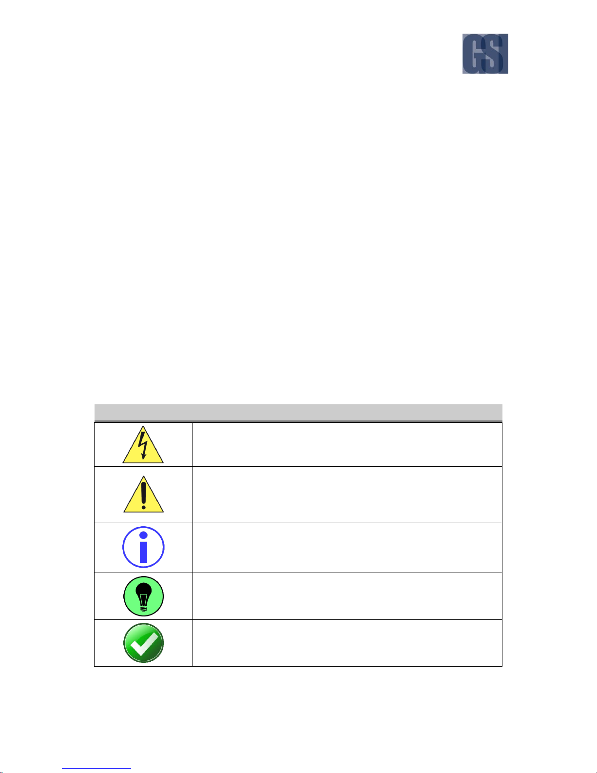
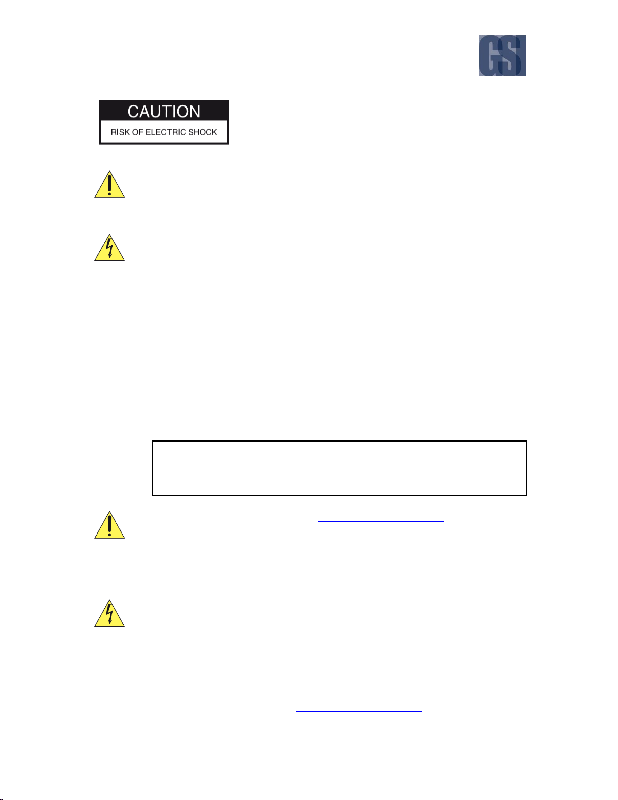
SAFETY AND INFORMATION SYMBOLS USED IN THIS MANUAL
This symbol is intended to alert the user to the presence of uninsulated
“dangerous voltage” that may be of sufficient magnitude to constitute a
risk of electric shock to persons.
This symbol is intended to alert the user to the presence of important
operating and maintenance instructions in the literature accompanying this
product. Failure to heed these warnings or instructions may damage the
product or cause it to operate incorrectly.
This symbol indicates text of importance or special significance in the
accompanying product literature. These may be important operating
instructions or supplemental information.
This symbol draws the user’s attention to time-saving tips and helpful
guidelines for using the product’s features.
This symbol draws the user’s attention to recommended best practices
which should be observed when installing and using the product.
G4-304SD1 User Manual & Install Guide
8 of 149
The battery must be disconnected from the vehicle before
working on the electrical system of the vehicle when installing,
servicing or removing Gatekeeper products.
Preparing to Install
Customers shall be responsible for addressing any systems on the bus that require
attention as a result of disconnecting the bus battery. This includes, but is not limited
to, entering a radio theft code, programming radio stations etc.
Installing the product
All Gatekeeper Systems employees or contractors who perform electrical work (eg.
installing, servicing or removing a G4-304SD1, installing a backup camera system, etc)
on a customer vehicle shall ensure that the battery in the vehicle is disconnected before
work commences.
Operating the product
The G4-304SD1 has an operating temperature range of -40°C to +65°C. It is good
practice to ensure that the product is mounted in a suitable location which does not
exceed acceptable temperature ranges during the course of normal operations.
Do not remove the cover of the product as this will void the warranty.
When a system has shipped with a GPS antenna, please ensure that the GPS antenna is
mounted externally on the roof of the bus with a clear view of the sky, and with the
magnetic side facing down.
The SD Card is specially formatted for use in your G4-304SD1. Please do not format it
yourself using Microsoft Windows. A SD card from a G4-304SD is not compatible with
the G4-304SD1 and so would require to be formatted in the G4-304SD1 prior to use.
Prior to removing the SD card for viewing video on a pc, it is essential that the G4304SD1 be fully powered down before removal of the SD card. Failure to do this will
result in data corruption and thereby loss of video.
Updating the product
Firmware updates (available from www.gatekeeper-systems.com) are system and
product model specific. These firmware updates must be applied to the G4-304SD1
system only.
Repairing the product
Your G4-304SD1 doesn’t have any user-serviceable parts. Do not open or disassemble
it, or attempt to repair it or replace any components.
Disassembling the G4-304SD1 may damage it or may cause injury to you. If your
product needs service, is damaged, or malfunctions, contact Gatekeeper Systems for
assistance. If you attempt to open it, you risk damaging your product, and such damage
isn’t covered by the warranty on your G4-304SD1.
If at any time there is a question about how to proceed, please contact Gatekeeper Systems immediately
at either 1-888-666-4833 or 1-604-864-6187 for assistance. Review all available installation
documentation, including technical bulletins. Additional resources, technical bulletins and product
tutorials can be found in the Support section of www.gatekeeper-systems.com.
G4-304SD1 User Manual & Install Guide
9 of 149
2 Your G4-304SD1 at a Glance
2.1 Take a Tour
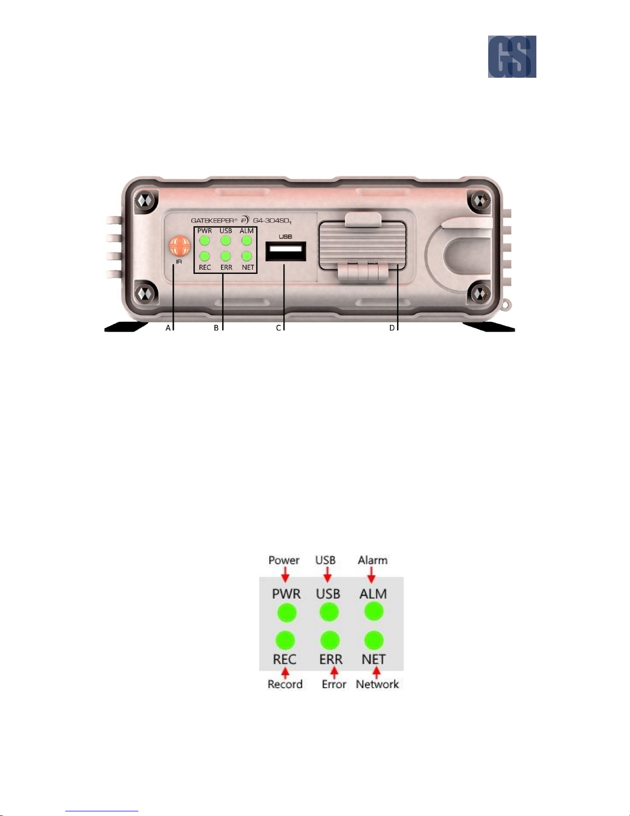
This is the front panel of the G4-304SD1:
Figure 2-1 Front View of the G4-304SD1
This panel is only available when the system key has been used to open the front of the housing.
A. IR Receiver: If installed, used in conjunction with the IR Remote control for system navigation.
B. LED Status Indicators: Status indicator lights which light up and/or flash to alert the user to
the device’s operational status and/or alarm status.
C. USB Port: Supports external USB flash drives which can be used for saving/uploading
configuration files, updating system firmware and downloading of recorded video/event files.
When not in use, the port is covered by a port cover.
D. SD Card Slot: The SD Card is installed in this slot. The slot is protected by a cover which is
only removed when the SD Card needs to be accessed.
Figure 2-2 Close Up View of the G4-304SD1 Status Indicator Lights
G4-304SD1 User Manual & Install Guide
10 of 149
LED
Description
PWR
Illuminated blue indicates the device is powered.
USB
Illuminated green indicates that the device is connected.
ALM
Illuminated red indicates that a sensor has triggered an alarm.
REC
Illuminated green indicates that the device is recording.
ERR
Illuminated orange indicates for hardware error.
NET
Illuminated green indicates network connection is available.
(Note: The LAN LED status light is currently not supported)
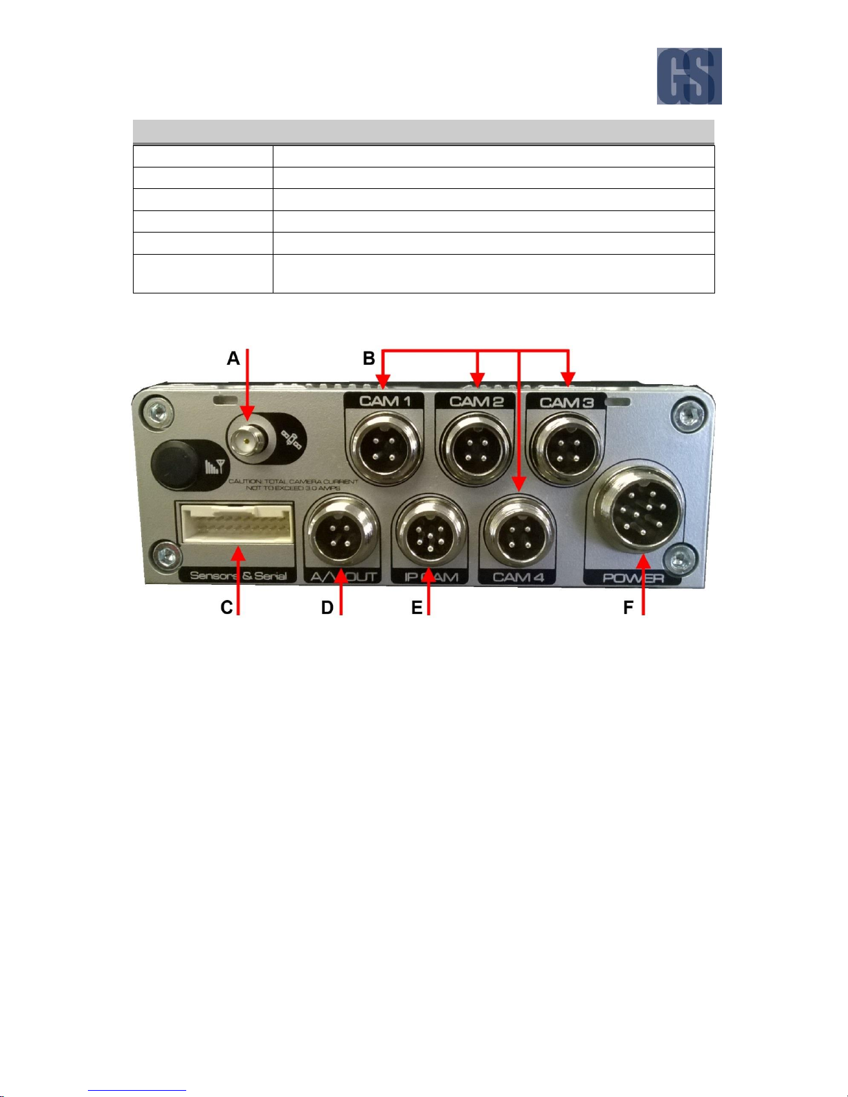
Figure 2-3 Rear View of the G4-304SD1
A. GPS Antenna In: This is the connection point for the external GPS antenna. If there is no GPS
antenna attached, this port should be covered with a rubberized cap.
B. Four analog camera connectors.
C. Serial/Sensor cable (CAB000376) connection.
D. A/V Out port. Use CAB000390.
NOTE: Only used at setup.
E. IP Camera connector. Use CAB000377.
F. Power In: This is the power input port for the device.
G4-304SD1 User Manual & Install Guide
11 of 149
2.2 What’s Included
The following items are included as part of your basic product package.
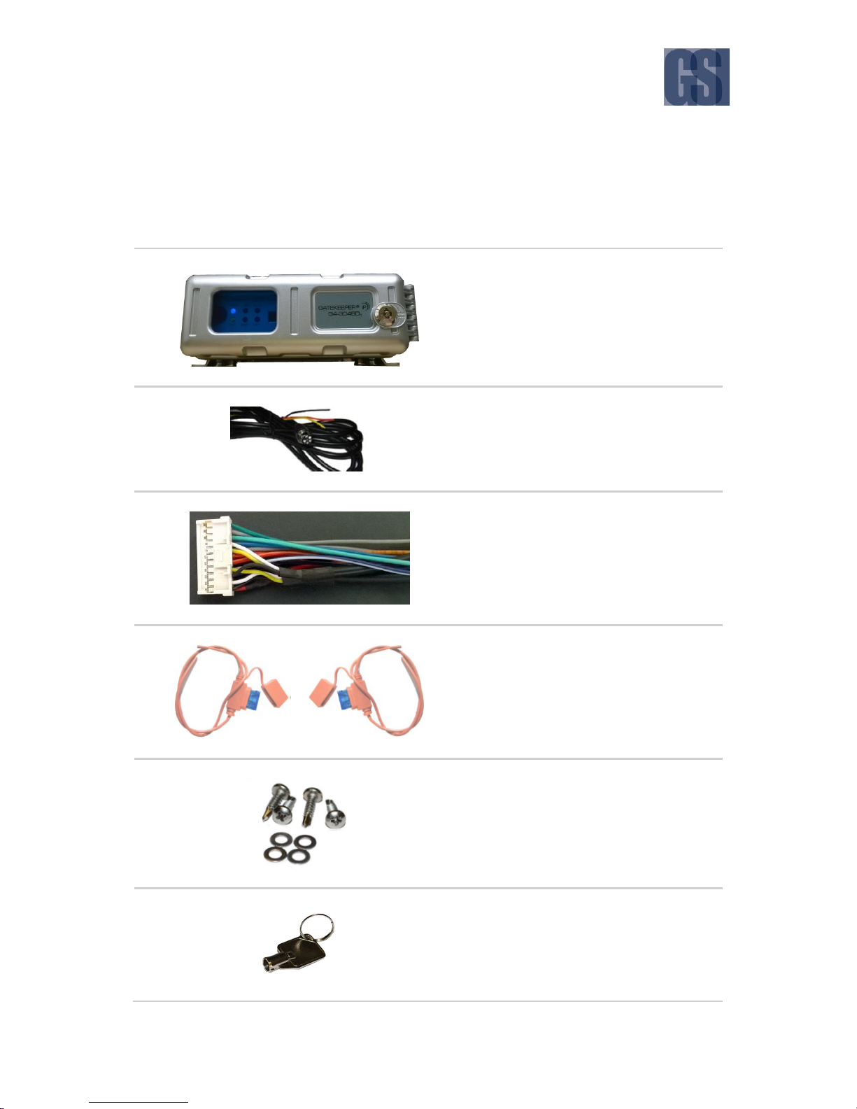
G4-304SD1 Digital Video Recorder
(G4-304SD1 Assembly)
Your new mobile digital video recorder
with a state of the art hard disk drive
suspension system and smart thermal
management technology.
Power Cable
(CAB000360)
This is the vehicle power ignition cable for
powering the G4-304SD1 and its
connected accessories.
Sensor Cable
(CAB000376)
This is the sensor cable for connecting the
various sensor input to the G4-304SD1.
Power Line Fuse
Ignition Line Fuse
Fastening Screws
Front Cover Key

G4-304SD1 User Manual & Install Guide
12 of 149
There are numerous customisable options and accessories which can tailor the product installation to
fit your unique operating environment and requirements.
Please contact Gatekeeper Systems for information on optional download kits and other accessories for
use with your product.
G4-304SD1 User Manual & Install Guide
13 of 149
3 Getting Started
3.1 Learning How to Navigate
Your G4-304SD1 comes with a simple graphical user interface from which you can access all the features
and functions. You can select from a choice of intuitive interface devices with which to navigate the
system. Depending on your product package, your G4-304SD1 will have come bundled with one of the
following accessories for accessing the user interface.
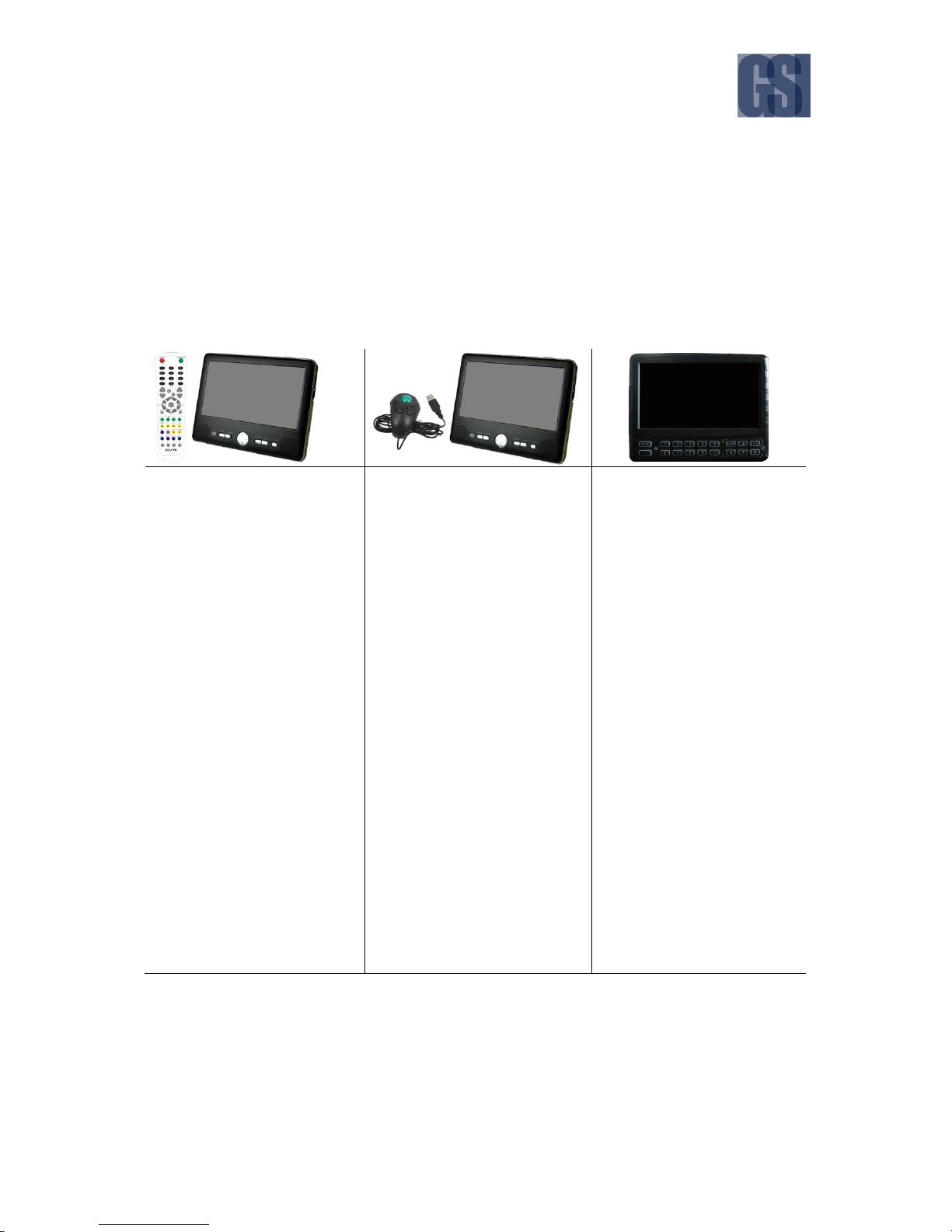
IR Remote Control
(G4-304SD1 RemoteCtrl)
This is an infra-red remote
control which can be used to
access the DVR functions and
menu system.
The DVR screens and menu
options are displayed on the
accompanying LCD monitor.
The IR Remote Control enables
you to move an on-screen
cursor which allows you to
select an on-screen button or
option by highlighting it.
Pressing the buttons on the IR
Remote Control will then allow
you to perform the selected
action.
Finger Mouse
(FDM-G51)
This is a trackball mouse which
enables access to the G4-304SD1
functions and menu system
through a simple point-and-click
interface.
The G4-304SD1 menu and
navigation actions are displayed
on the accompanying LCD
monitor.
You will be able to move the onscreen pointer using the Finger
Mouse, and interact with the
system by positioning the
pointer over the various onscreen buttons or options, and
clicking the buttons on the
Finger Mouse to perform an
action.
Interactive Control Display
(G4-ICD2 Assy)
This interactive control display
(ICD2) is a touchscreen LCD
display which allows access to
the G4-304SD1 functions and
menu system through an
intuitive touch interface.
The G4-304SD1 screens and
menu options are presented
on the ICD2 screen itself, and
you will be able to interact with
the system and perform
actions by touching or tapping
the on-screen buttons and
options.
G4-304SD1 User Manual & Install Guide
14 of 149
3.1.1 Using the IR Remote Control
The infra-red remote control, together with the accompanying LCD monitor, allows you to access the
DVR functions and menu system.
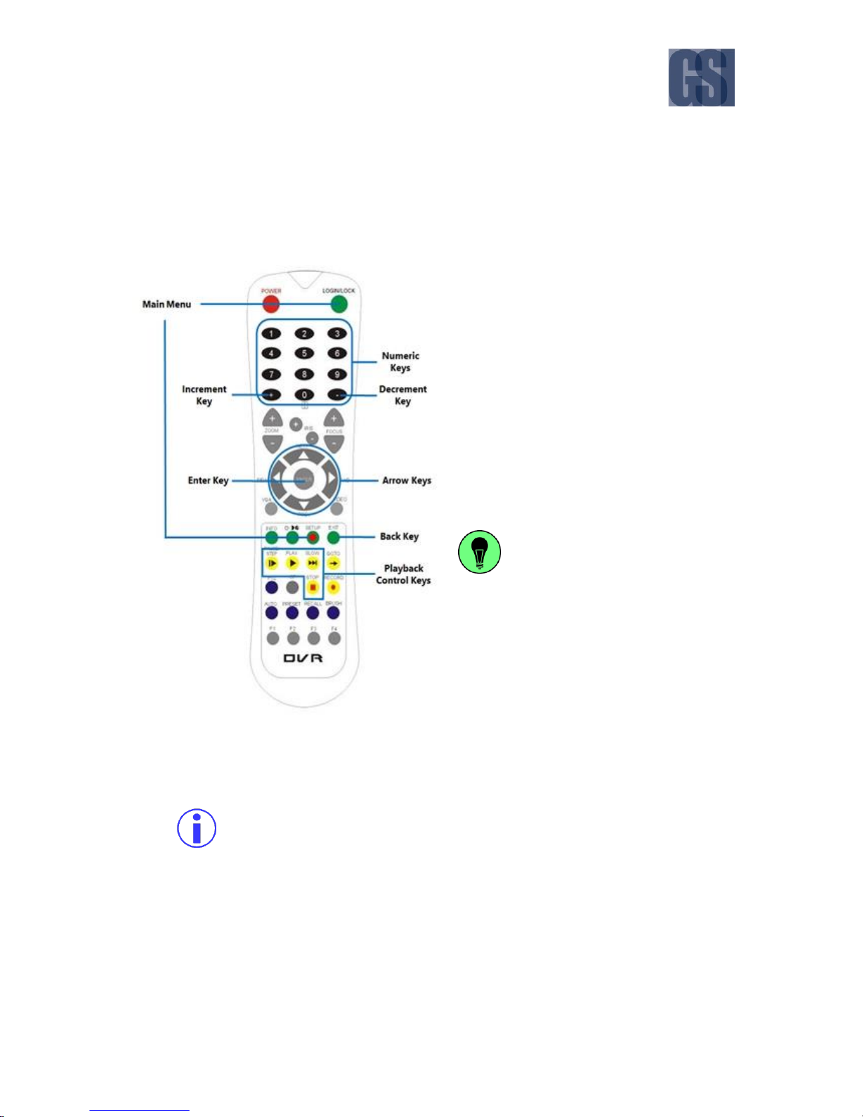
Front View of the IR Remote Control
Setup: To access the menu use the Setup
button. It is also possible to use the Login/Lock
screen button.
Arrow Keys: These buttons can be used to
move the cursor or menu highlight to the left
and right as well as up and down in order to
select a button or menu item.
Enter Key: Pressing this button will select the
highlighted menu item.
Numeric Keys: These buttons are used for
entering numeric input.
When viewing video streams,
pressing any button (from 1-9) will
immediately jump to the video
stream from the corresponding
camera. Pressing the button zero (0)
will cycle through the camera
channels iteratively.
Increment Key: This button provides a quick
way to increase the parameter value by one
unit (in configuration screens).
Decrement Key: This button provides a quick way to decrease the parameter value by one
unit (in configuration screens).
Main Menu: This two buttons provide a quick way to return to the main menu.
Access to the main menu requires that the user is logged into the system with correct
username and password.
Back Key: Pressing this button will return you to the previous screen. If you are at the live video
view screen, this button will toggle the on-screen quick menu on and off.
Playback Control Keys: When you are viewing video playback, these keys will allow you to easily
Pause/Step through the video frame by frame, Play the video at normal speed, play the video
at Slow speed (pressing repeatedly cycles through the available slow motion speed settings),
and Stop the video playback.
G4-304SD1 User Manual & Install Guide
15 of 149
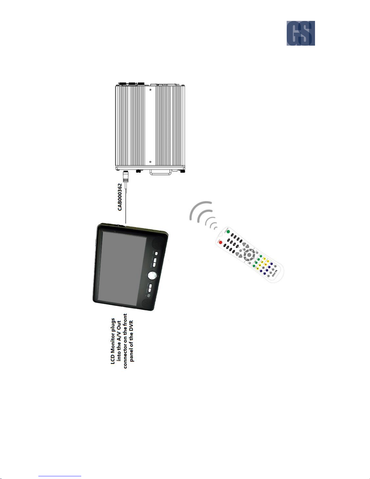
How to Connect the IR Remote Control and LCD Monitor
Connecting the IR Remote Control and LCD Monitor

G4-304SD1 User Manual & Install Guide
16 of 149
3.1.2 Using the Trackball Mouse.
The trackball mouse, together with the accompanying LCD monitor, provides one way to access the G4304SD1 menu and functions using a familiar graphical user interface point-and-click system.
Figure 3-1 Side View of the Finger Mouse
Right Button: When viewing video streams, pressing this button will toggle between showing
and hiding the on-screen quick menu.
Track Ball: This is a finger-operated mouse ball which moves the on-screen mouse pointer in
response to the movement of the track ball. This is used to move the pointer to the left and
right as well as up and down in order to point to a desired button or menu item.
Trigger Button: Pressing this button will select the screen area, button or menu item that the
on-screen pointer is currently pointed at.
Pressing and holding the Trigger Button whilst simultaneously moving the Track Ball will
enable you to perform a click-and-drag action. This allows you to interact with moveable
screen options such as slider bar controls, and to reposition moveable text visually and
intuitively.
G4-304SD1 User Manual & Install Guide
17 of 149
How to Connect the Finger Mouse and LCD Monitor
Figure 3-2 Connecting the Finger Mouse and LCD Monitor
G4-304SD1 User Manual & Install Guide
18 of 149
3.1.3 Using the Interactive Control Display (ICD2)
The ICD2 is a full featured touch display that makes navigating the device menu system very intuitive.
Besides the touch function, this accessory also has a number of buttons which act as hotkeys allowing
the user to quickly select and go to different functions.
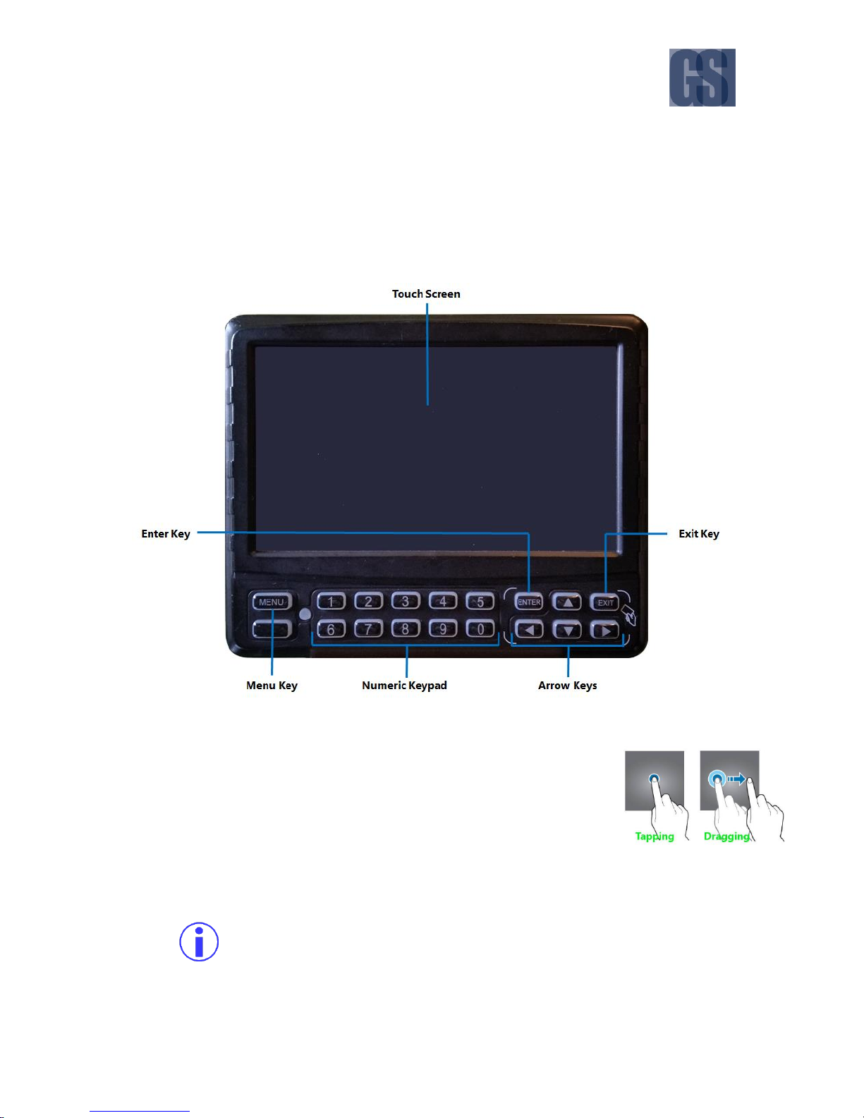
Figure 3-3 Front View of the ICD2
Touch Screen: A single tap anywhere on the screen (when showing video
streams) will bring up the on-screen quick menu. Another single tap
anywhere on the screen will hide the quick menu again. At all times,
tapping on an on-screen field, tab or button in the menu system will select
it. Tapping, holding and dragging will also work for sliders and moveable
items – allowing you to perform click-and-drag actions.
Menu Key: When viewing video streams, pressing this button will immediately jump to the main
menu screen.
Access to the main menu requires that the user is logged into the system with correct
username and password.
G4-304SD1 User Manual & Install Guide
19 of 149
Exit Key: Pressing this button will move the user back to the previous screen. If viewing video
streams, then pressing this button will toggle between showing and hiding the on-screen quick
menu (similar to a single tap on the touch screen).
Arrow Keys: These buttons can be used to move the cursor or menu highlight to the left and
right as well as up and down in order to select a button or menu item.
Enter Key: Pressing this button will select the highlighted menu item (similar to tapping on it).
Numeric Keypad: These buttons are used for entering numeric input.
When viewing video streams, pressing any button (from 1-9) will immediately jump
to the video stream from the corresponding camera. Pressing the button zero (0) will
cycle through the camera channels.
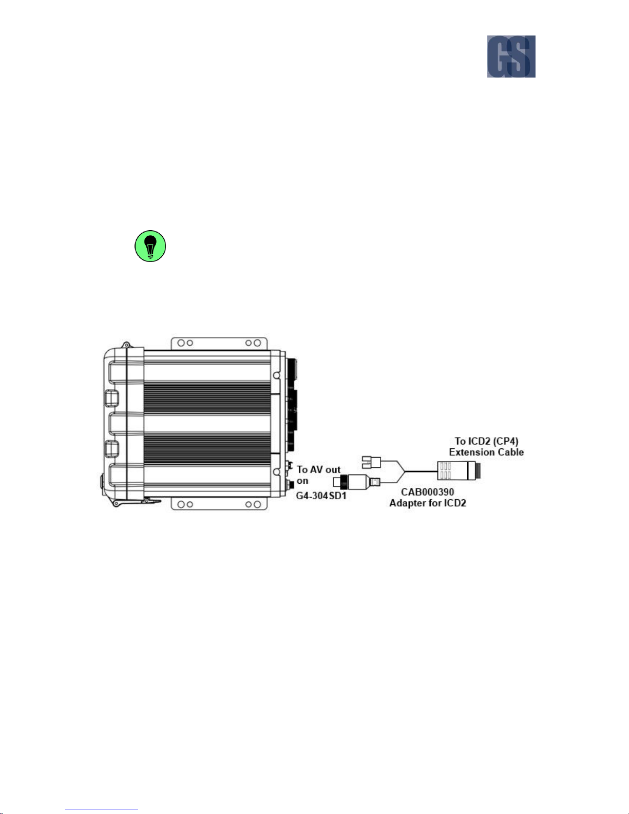
How to Connect the ICD2
Figure 3-4 Connecting the ICD2

G4-304SD1 User Manual & Install Guide
20 of 149
3.2 Guide to Common Navigation Actions
The following table provides a summary of commonly used navigation functions.
No.
Action
IR Remote
Finger Mouse
ICD2
1
Navigating through
the screens.
Use the Arrow Keys to
move the cursor to
highlight different
menu options.
Move the on-screen
pointer using the Track
Ball and point to the
desired menu option.
Use your finger to tap
the desired menu
option.
2
Selecting an item on
the screen.
Note: Also referred to
as clicking the item.
Move the cursor using
Arrow Keys until the
desired item is
highlighted, then press
the Enter Key to select
it.
Move the on-screen
pointer until it points to
the desired item, then
click the Trigger Button
to select it.
Tapping on the desired
item with your finger
will select it.
3
Pressing an onscreen button.
Note: Also referred to
as clicking the button.
Move the cursor using
Arrow Keys until the
on-screen button is
highlighted, then press
the Enter Key.
Move the on-screen
pointer using the Track
Ball until it is situated
over the on-screen
button, then click the
Trigger Button.
Tap the on-screen
button with your finger.
4
Entering text into a
selected
alphanumeric field.
Move the cursor using
Arrow Keys until the
desired text field is
highlighted, then press
the Enter Key. An onscreen keyboard will
be displayed. Type
your text by moving
the cursor with Arrow
Keys to highlight each
letter and pressing the
Enter Key.
Move the on-screen
pointer using the Track
Ball until it is situated
over the text field, then
click the Trigger
Button. An on-screen
keyboard will be
displayed. Type your
text by moving the
pointer with Track Ball
to each letter and
clicking the Trigger
Button.
Tap on the text field
with your finger. An onscreen keyboard will be
displayed. Use the onscreen keyboard to type
the text with your
fingers.
5
Entering numbers
into a selected
numeric field.
Move the cursor using
Arrow Keys until the
desired numeric field
is highlighted, then
press the Enter Key.
An on-screen keypad
will be displayed. Type
the number by moving
the cursor with Arrow
Keys to highlight each
Move the on-screen
pointer using the Track
Ball until it is situated
over the numeric field,
then click the Trigger
Button. An on-screen
keypad will be
displayed. Type your
numbers by moving the
pointer with Track Ball
to each digit and
Tap on the numeric field
with your finger. An onscreen keypad will be
displayed. Use the onscreen keypad to type
the numbers with your
fingers.
Alternatively, you may
also use the Numeric

G4-304SD1 User Manual & Install Guide
21 of 149
No.
Action
IR Remote
Finger Mouse
ICD2
digit and pressing the
Enter Key.
Alternatively, you may
also use the Numeric
Keys on the IR Remote
Control to type the
numbers directly, once
the numeric field has
been selected.
clicking the Trigger
Button.
Keypad on the ICD2 to
type the numbers
directly, once the
numeric field has been
selected.
6
Click and drag an
item.
This action can’t be
performed using an IR
Remote.
Move the on-screen
pointer using the Track
Ball until it is situated
over the item, then click
and hold the Trigger
Button.
Whilst still holding the
Trigger Button, now
simultaneously move
the on-screen pointer
using the Track Ball.
This will drag the item in
the direction which you
are moving the pointer.
Tap your finger on the
item and continue to
hold. Now, without
releasing your finger,
move it in the direction
you desire. This will
drag the item in the
direction which you are
moving your finger.
7
Go back to previous
screen.
Press the Exit button
on the IR Remote.
Not applicable. Use the
on-screen controls.
Press the Exit button on
the ICD2.
8
Display the on-screen
quick menu.
Note: On-screen quick
menu is only accessible
from the live video
view screens.
When you are at any
live video view screen,
press the Exit button
on the IR Remote to
toggle between
displaying and hiding
the on-screen quick
menu.
Note that at any other
screen, the Exit button
returns you to the
previous screen.
When you are at any
live video view screen,
press the Right Button
on the Finger Mouse to
toggle between
displaying and hiding
the on-screen quick
menu.
When you are at any
live video view screen,
press the Exit button on
the ICD2 to toggle
between displaying and
hiding the on-screen
quick menu.
Note that at any other
screen, the Exit button
returns you to the
previous screen.
9
Jump to the main
menu.
Press either the
Login/Lock button or
the Setup button on
the IR Remote.
Not applicable. Use the
on-screen controls.
Press the Menu button
on the ICD2.

G4-304SD1 User Manual & Install Guide
22 of 149
No.
Action
IR Remote
Finger Mouse
ICD2
Note that if you are in
the midst of video
playback, then you
need to Exit the
playback first before
you can jump to the
main menu.
10
Jump to a particular
channel.
While viewing video,
press any one of the
numbered buttons
(from 1 to 9) on the
numeric keys of the IR
Remote to switch the
view to the
corresponding channel
number.
Not applicable. Use the
on-screen controls.
While viewing video,
press any one of the
numbered buttons
(from 1 to 9) on the
numeric keypad of the
ICD2, or double tap the
channel on the screen
to switch to the
corresponding channel.
11
Cycle to the next
channel.
Press the ( 0 ) button
on the numeric keys of
the IR Remote.
Not applicable. Use the
on-screen controls.
Press the ( 0 ) button on
the numeric keypad of
the ICD2.
12
Playback controls for
video.
When you are viewing
video playback, press
the Setup key to
display/hide the onscreen video playback
controls which you
then use to adjust the
video playback.
Besides that, you may
also use the following
dedicated keys on the
IR Remote to perform
the following actions:
Pause/Step through
the video frame by
frame.
Play the video at
normal speed.
Slow motion playback
(pressing repeatedly
cycles through the
available slow motion
speed settings).
Stop the video
playback.
When you are viewing
video playback, press
the Right Button to
display/hide the onscreen video playback
controls.
You may then use the
on-screen controls to
adjust the video
playback.
When you are viewing
video playback, tap
anywhere on the screen
to display/hide the onscreen video playback
controls.
You may then use the
on-screen controls to
adjust the video
playback.
G4-304SD1 User Manual & Install Guide
23 of 149
3.3 The G4-304SD1 Startup Screen Layout
Upon startup, the screen of the G4-304SD1 will display the live video streams from the various cameras
attached to the G4-304SD1. Users can select and configure how many video channels to be displayed
on the screen for monitoring purposes. The screen also serves as an interface into the menu system of
the G4-304SD1 where users can playback recorded video, and access the configuration menu to change
the device configuration settings.
The screen layout will stay the same regardless of whether an ICD2 is being used, or an LCD monitor
being used along with a Finger Mouse or IR Remote control. This ensures that the user always has a
familiar interface and consistent methodology to interact with the menu system and device functions.
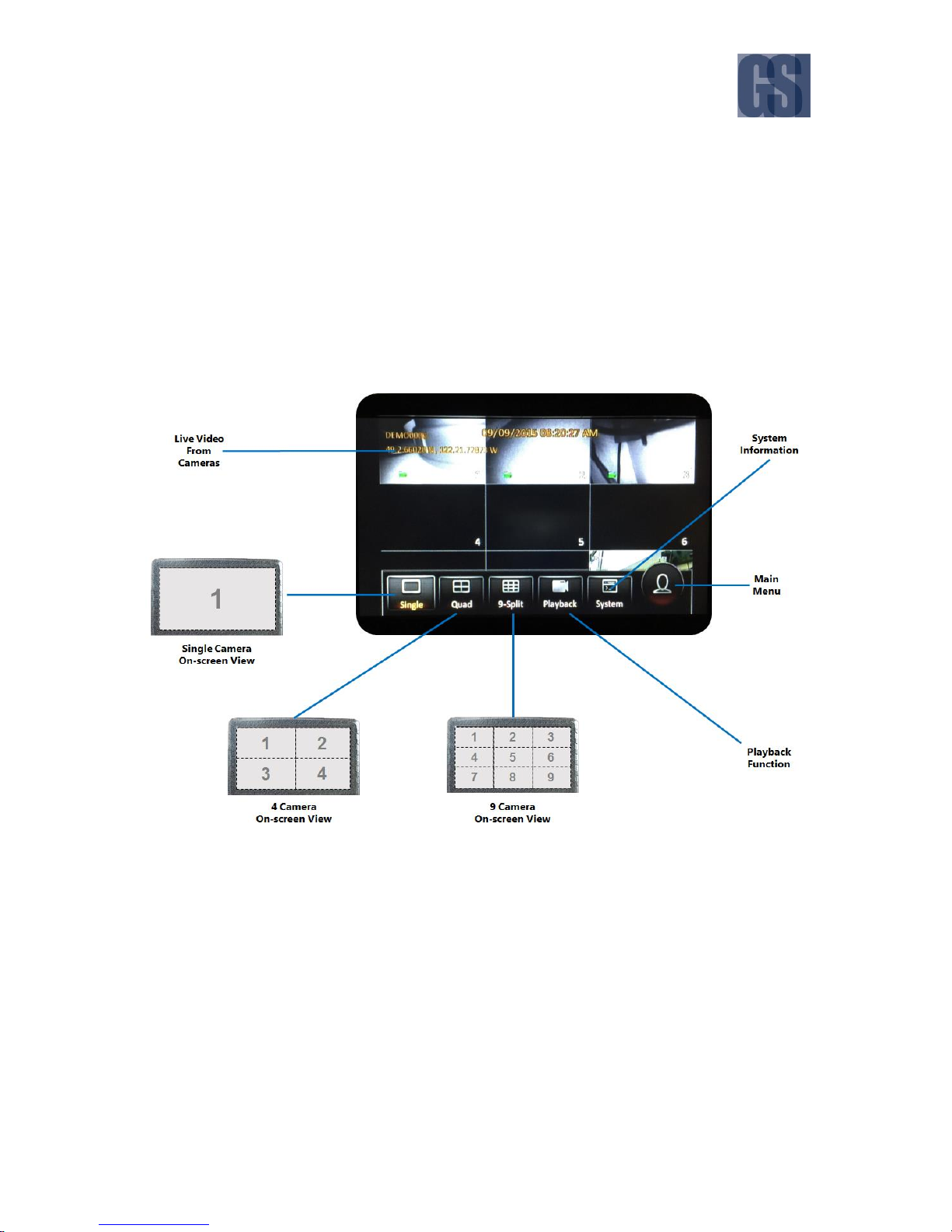
Figure 3-5 G4-304SD1 Startup Screen
Live Video From Cameras: By default upon system startup, the screen will display live video from
the camera attached to channel one in single camera full onscreen view. Clicking anywhere on
the video screen will bring up the on-screen quick menu where the user can select from several
different display options.
Single Camera On-screen View: This view displays the video stream from a single camera on the
entire screen.
4 Camera On-screen View: This view splits the screen into four sections (using a 2x2 grid layout),
and displays the video streams from four cameras simultaneously on the screen.
G4-304SD1 User Manual & Install Guide
24 of 149
9 Camera On-screen View: This view splits the screen into nine sections (using a 3x3 grid layout),
and displays the video streams from cameras simultaneously on the screen.
System Information: This displays the system information screen where the user can view various
device information such as version information, active modules, server status, environment data,
and storage size.
Main Menu: This opens up the main menu screen. This function requires the user to be logged
in. If the user is not logged in yet, the system will display the login screen.
Playback Function: This opens up the recorded video playback screen. This function requires the
user to be logged in. If the user is not logged in yet, the system will display the login screen.
3.4 Viewing Live Video
Single Camera On-screen View
When the screen is in Single Camera On-screen View mode, camera from a single camera
channel will be shown on the entire screen.
In order to select a specific camera for viewing, you may press any of the keys [1-5] on the ICD2
to immediately jump to that channel and display the video stream from the corresponding
camera.
You can also cycle through the channels iteratively by pressing the key zero [0] on the ICD2.
Figure 3-6 Cycling through the Video Channels in Single View

G4-304SD1 User Manual & Install Guide
25 of 149
4 Camera On-screen View
In 4 Camera (Quad) On-screen View mode, the screen is split into four sections (using a 2x2
grid layout) and video from four cameras is simultaneously shown on the screen.
In order to select a specific camera for viewing, you may press any of the keys [1-5] on the ICD2
to immediately jump to that channel and display the video stream from the corresponding
camera. This will switch the display to Single Camera On-screen View to display the video from
the selected camera.
Alternatively, with the Finger Mouse or the ICD2, you could also click on any video stream on
the (2x2) grid display to immediately jump to that channel and display the video from the
corresponding camera. This will switch the display to Single Camera On-screen View to display
the video from the selected camera.
Once you have selected a channel to view, you can cycle through the available channels
iteratively in quad grid display mode by pressing the key zero [0] on the ICD2.
9 Camera On-screen View
In 9 Camera On-screen View mode, the screen is split into nine sections (using a 3x3 grid layout)
and video from all connected cameras is simultaneously shown on the screen. Note: all other
areas will display a black box.
In order to select a specific camera for viewing, you may press any of the keys [1-5] on the ICD2
to immediately jump to that channel and display the video stream from the corresponding
camera. This will switch the display to Single Camera On-screen View to display the video from
the selected camera.
Alternatively, with the Finger Mouse or the ICD2, you could also click on any video stream on
the quad grid display to immediately jump to that channel and display the video from the
corresponding camera. This will switch the display to Single Camera On-screen View to display
the video from the selected camera.
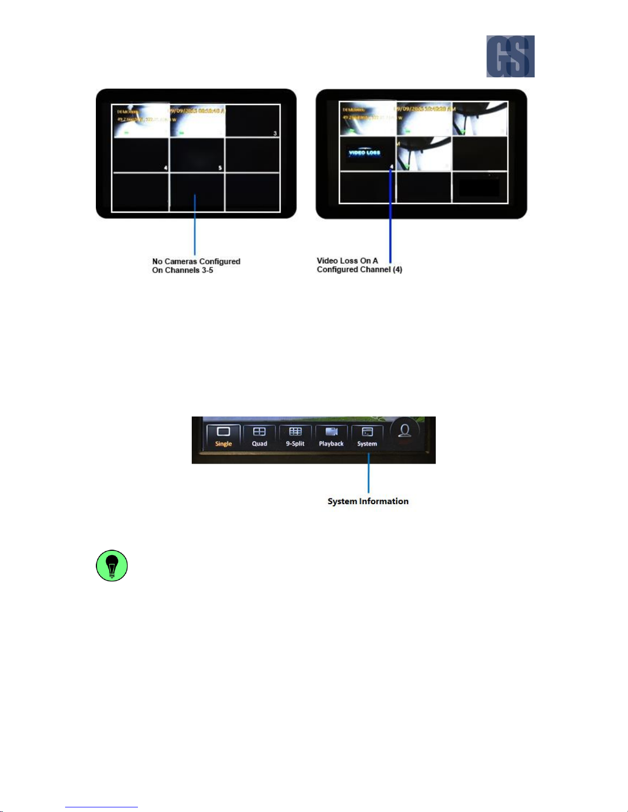
Notes
Channels which do not have cameras configured on them will just show a black display.
Any channel which is configured with a camera, but is not receiving any video signal
from that camera will show a Video Loss message on the screen.
G4-304SD1 User Manual & Install Guide
26 of 149
Figure 3-7 Example of Video Loss
3.5 Quick View of System Status Information
Selecting the System Information button on the on-screen quick menu will display the system
information screen where the user can view various device information such as version information,
active modules, server status, environment data, and storage size.
Figure 3-8 System Information Function on Quick Menu
This System Information function is a quick and easy way to access and view all the important
information about your device’s status and configuration from one central location. It can be
accessed directly from the on-screen quick menu without the need to log in.
The following is a list of the device information which can be viewed by the user from the System
Information function.
G4-304SD1 User Manual & Install Guide
27 of 149
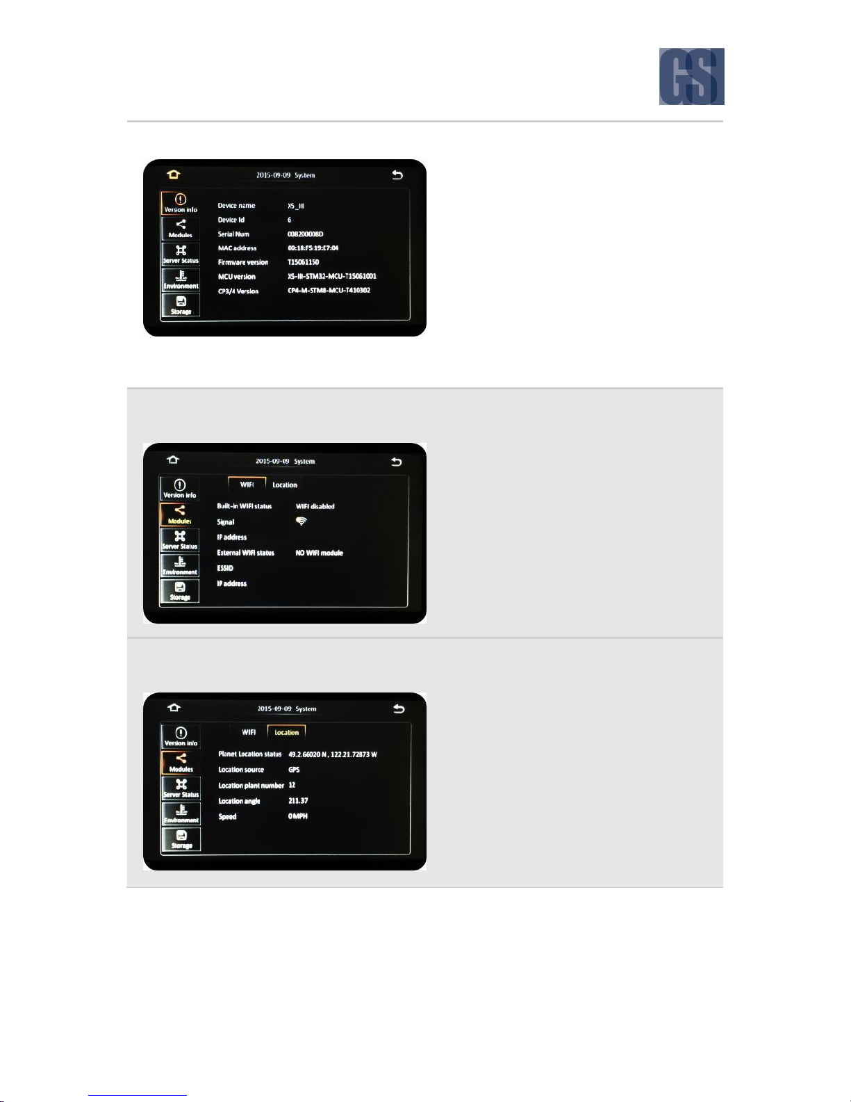
1. Version
This screen shows a summary of the various
device hardware identification numbers, and
also the version numbers of the firmware that is
running on the device.
The information shown is as follows:
Device Name
Device ID
Serial Number
MAC Address – this is the G4-304SD1
LAN MAC
Firmware Version
MCU Version
CP3/4 Version – this is the ICD firmware
2. Modules - WiFi
(Not supported by Gatekeeper)
This screen shows a summary of the WiFi
connection status of the device. This includes
information on whether WiFi is enabled, the
signal strength, connection point, and the IP
address of the device.
The information shown is as follows:
Built-in WiFi Status
Signal Strength
IP Address
External WiFi Status
ESSID
IP Address
3. Modules - Location
(Not supported by Gatekeeper)
This screen shows the GPS data giving the
current device location (in terms of GPS
coordinates), source of the location data, as well
as some additional details such as the location
triangulation data and current speed.
The information shown is as follows:
Planet Location Status
Location Source
Location Plant Number
Location Angle
Speed
G4-304SD1 User Manual & Install Guide
28 of 149
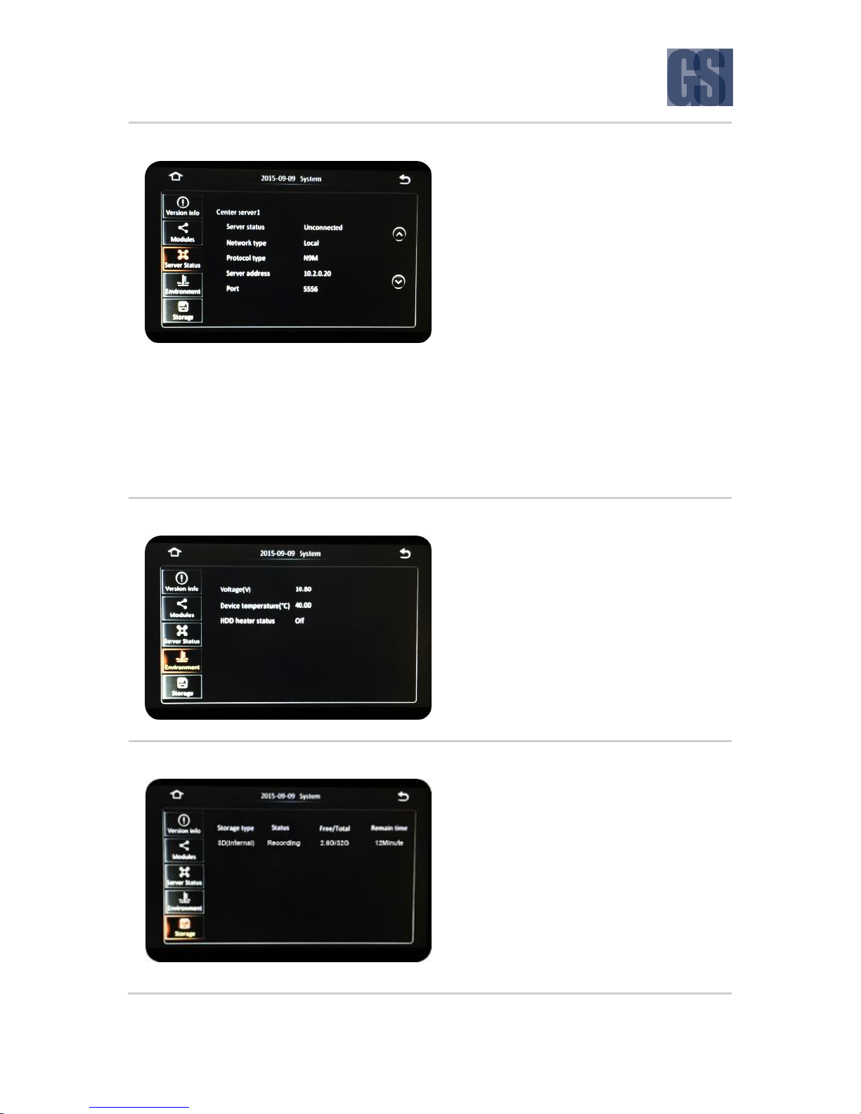
4. Server Status
This screen shows the details of the Center
Server that the device is setup for connection to
(summarising the connection status and type, as
well as the connection address and port
number).
Note: These settings are only applicable when the
device is setup for a network connection within a
Gatekeeper Wireless Configuration.
The information shown is as follows:
Server Status
Network Type
Protocol Type
Server Address
Port
You can click the ( ^ ) and ( v ) buttons to scroll
through the status information for different
servers which are set up in the system.
5. Environment
This screen summarises the current
environmental conditions of the device. It shows
the operating voltage, device temperature in
Celsius, and whether the device’s smart thermal
management system is currently active.
The information shown is as follows:
Voltage
Device Temperature (°C)
HDD Heater Status
6. Storage
This screen lists the storage devices which are
currently attached to the device. It also indicates
whether the device is currently recording to the
listed storage devices, their total storage
capacity, as well as remainder capacity in
storage space as well as estimated recording
time.
The information shown is as follows:
Storage Type
Status
Free/Total
Remain Time
G4-304SD1 User Manual & Install Guide
29 of 149
3.6 Logging into the System
In order to access many of the G4-304SD1’s advanced functions, you will need to be logged in to the
system. This is a security measure to ensure that access to sensitive functions and video data is restricted
to authorised users. Also, the system keeps an operations log which tags particular actions to usernames
for accountability and audit purposes.
Access to the following functions require the user to be logged in:
Access from the on-screen quick menu:
Playback
Access to the Main Menu and the following functions:
REC Search
Log Search
Setup ( * this function requires the user to be logged in as an administrator )
How to Log In
When attempting to access any of these functions, the system will check the log-on status of the user
before granting access to the function. If the user is not already logged in, the system will automatically
prompt the user to log in.
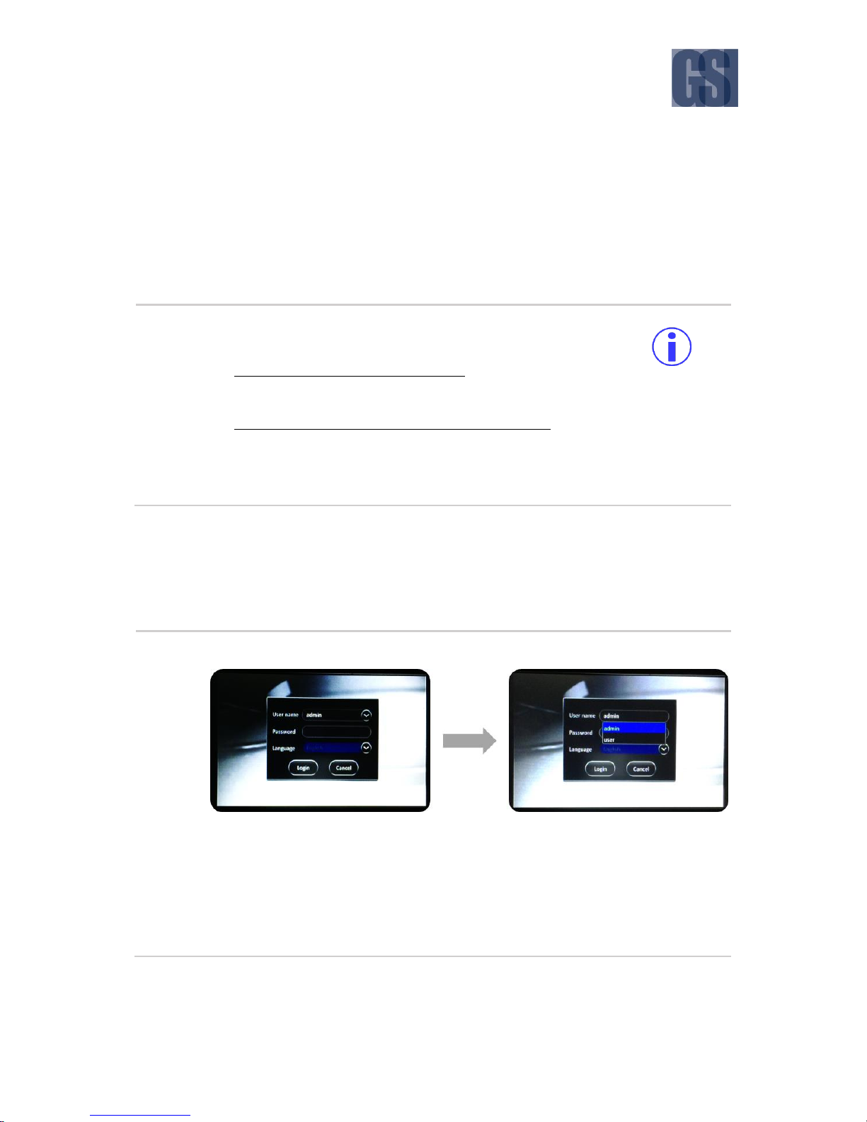
Step 1
System will display the log-in dialog box as shown below.
Click on the drop down ( v ) button at the right corner of the User Name field.
A drop down menu will appear which will list all the users who are set up to access
the system.
Select the user name to use for this log-in by clicking on the desired user name in
the list.
Your selected user name will be displayed in the User Name field.
G4-304SD1 User Manual & Install Guide
30 of 149
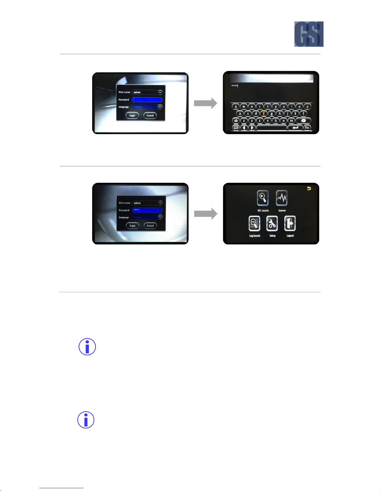
Step 2
Click on the Password field to enter the password.
Using the on-screen keyboard which is displayed, key in the password.
When done, press the Enter ( ) key on the on-screen keyboard.
Step 3
Click the ( Login ) button.
If the password is correct, you will be logged-in and allowed to access the advanced
functions of the G4-304SD1 and the Main Menu.
At any time, you may also cancel the log-in process by clicking the ( Cancel )
button.
Notes
The system ships with the following two default user credentials:
User name : admin ( * default administrator account )
Password : admin
User name : user
Password : user
You may change the default administrator user password, and also edit/add additional users
through the user management function in the configuration settings.
Normal users can access the Playback, REC Search and Log Search functions, but only
administrator level users can access all those functions, as well as the Setup function for
configuring the G4-304SD1.

G4-304SD1 User Manual & Install Guide
31 of 149
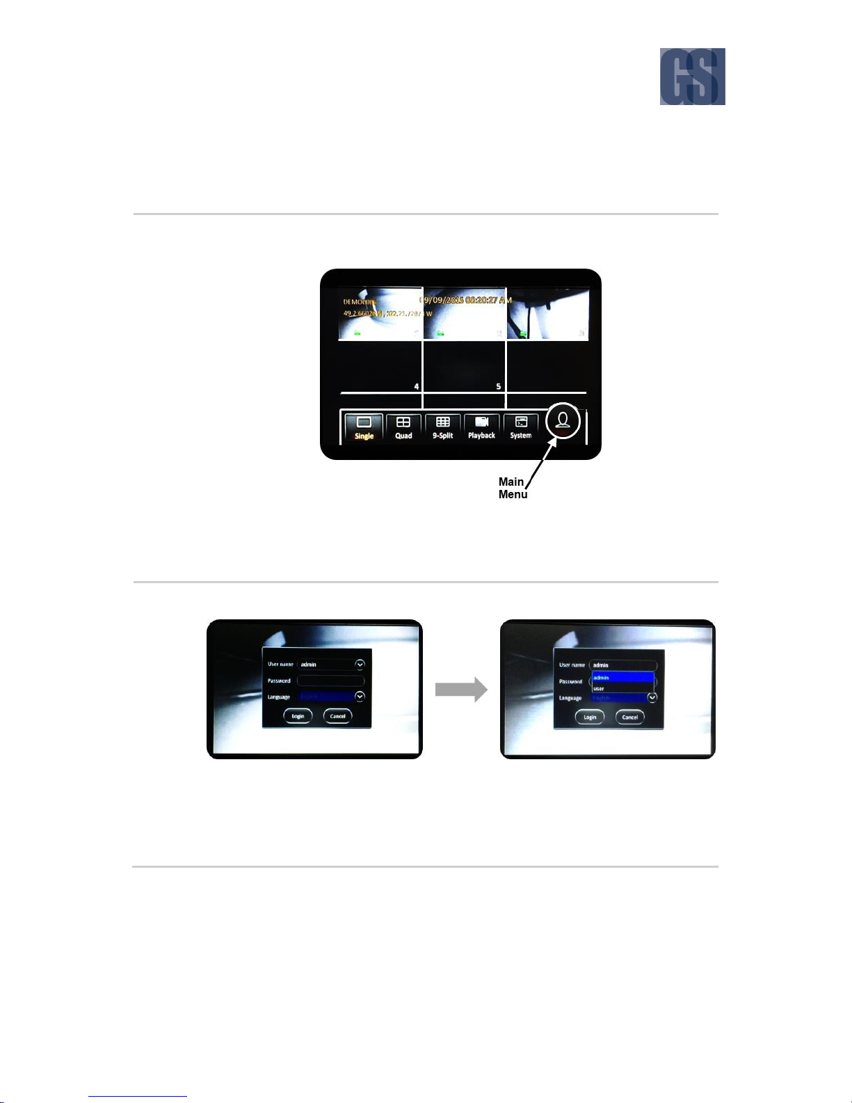
3.7 Understanding the Main Menu
The Main Menu can be accessed by clicking the Person icon on the far right of the on-screen quick
menu.
Figure 3-8 Accessing the Main Menu
The Main Menu has five options as shown in the following figure.
Figure 3-9 Options in the Main Menu
REC Search: Search for, view and save recorded video.

G4-304SD1 User Manual & Install Guide
32 of 149
System Information: View important system information.
Log Search: Search for, view and save log files.
Setup: View and make changes to the device configuration options.
Logout: Logout the current logged-in user. This will return the system to the live video view.
The REC Search and Log Search functions will be explained in the chapter on Viewing Recorded Data,
whilst the Setup function will be explained in the chapter on Configuring the G4-304SD1.

G4-304SD1 User Manual & Install Guide
33 of 149
4 Basic System Quick Start
Your G4-304SD1 will have already come pre-configured by Gatekeeper Systems with the most common
default settings which are applicable to most deployments – and you will only need to verify and adjust
the basic settings to get up and running. The following sections will guide you through the basic setup
process so that you can begin using your new product as soon as possible.
4.1 Step 1: Powering Up the G4-304SD1
The Gatekeeper Project Team are able to mount and install the device into the vehicle based on your
requirements and in accordance with industry best practices from years of experience. If you prefer to
mount the device yourself, please read Chapter 9 for detailed hardware installation instructions.
Turning your vehicle ignition on will automatically power up the G4-304SD1. When your vehicle ignition
is turned off, the device will automatically shut down after 5 minutes (you will be able to change this
later in the device settings).
4.2 Step 2: Connecting your Navigation Device
Once the device has powered up, please verify that you can see the display on your LCD monitor or
ICD2 with live video from connected cameras shown.
Figure 4-1 Live Camera View Shown on Device Startup
You may now use the supplied navigation device (either the Finger Mouse or ICD2) to perform the rest
of the basic setup process. For more details on connecting and using the navigation devices, please
read Section 3.1 and Section 3.2.
G4-304SD1 User Manual & Install Guide
34 of 149
4.3 Step 3: Logging In and Accessing System Configuration
You may now log into the system and go to the Main Menu where you can access the device Setup and
configuration settings.
Step 3.1
If you are using a Finger Mouse, click the Right Button, whereas ICD2 users can just
tap on the screen.
On the quick menu, click the Person icon. This will prompt you to login to the
system.
Step 3.2
System will display the log-in dialog box as shown below.
Ensure that admin is displayed in the User Name field.
If not, then click on the drop down ( v ) button at the right corner of the User Name
field. A drop down list of user names will appear where you will be able to click on
admin to select it.

G4-304SD1 User Manual & Install Guide
35 of 149
Step 3.3
Click on the Password field to enter the password.
Using the on-screen keyboard which is displayed, key in the password. For this
initial login, please key in the default password, which is: admin
When done, press the Enter ( ) key on the on-screen keyboard.
Step 3.4
Click the ( Login ) button.
The Main Menu will be shown.
Click on the ( Setup ) button to go to the device configuration screen.
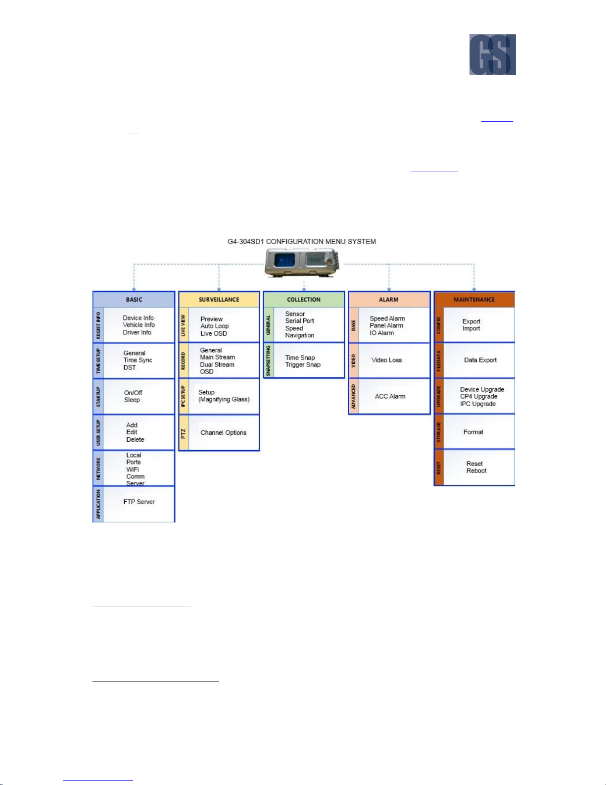
Understanding the Setup Menu System for System Configuration
The G4-304SD1 comes with a comprehensive setup menu system where you will be able to tailor almost
every aspect of the device operations to your unique fleet requirements.
The configuration options in the menu are broken into 5 major sections:
Basic – where you will be able to configure all the basic device preferences and operational
settings. For a detailed explanation, please see Section 6.3.
Surveillance – where you will be able to configure camera viewing; recording settings, as well
as set up new cameras. For a detailed explanation, please see Section 6.4.
Collection – where you will be able to configure all the settings related to collection of vehicle
and operations data from the device sensors, and also configure settings for taking snapshots
based on pre-set triggers. For a detailed explanation, please see Section 6.5.
G4-304SD1 User Manual & Install Guide
36 of 149
Alarm – where you will be able to configure recording, snapshot and other actions which the
device will perform when an alarm event occurs. For a detailed explanation, please see Section
6.6.
Maintenance – where you will be able to perform various maintenance actions, including data
export and firmware upgrades. For a detailed explanation, please see Section 6.7.
Each of these major configuration sections have their separate subsections as shown in the following
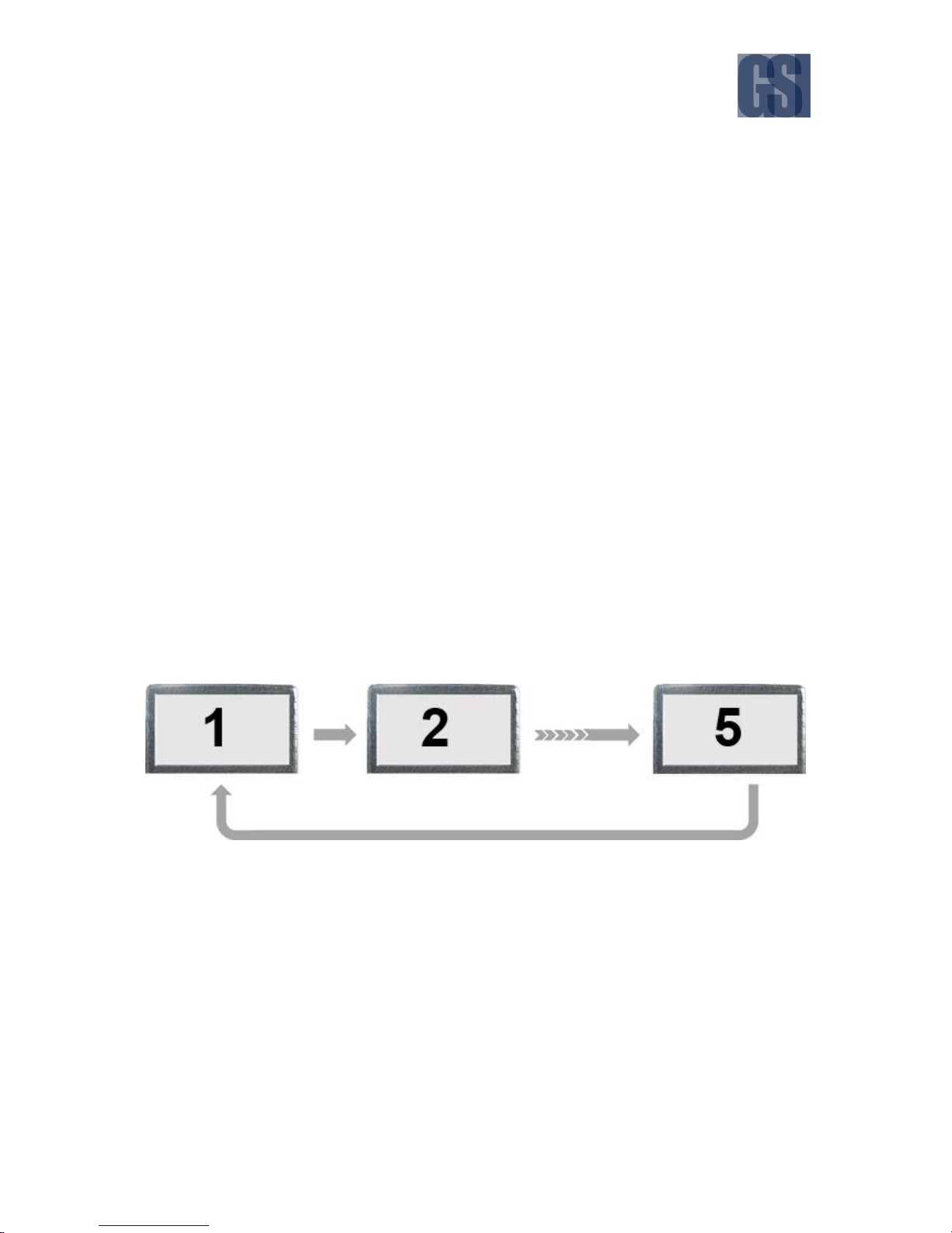
diagram.
Figure 4-2 Setup Menu System for Device Configuration
For the basic setup process, we will just need to verify and/or configure the settings in the subsections
highlighted with the red dotted lines in the diagram, as follows:
Under the Basic section:
Regist Info options
Time Setup options
Startup options
User Setup options
Under the Surveillance section:
Record options
IPC Setup options

G4-304SD1 User Manual & Install Guide
37 of 149
4.4 Step 4: Setting the Date and Time
The first step is to ensure that the date and time is set correctly in the device.
Navigate to: Main Menu Setup Basic Setup Time Setup
Please verify that the following default settings are correctly configured. For a detailed explanation of
each setting, please see Section 6.3.2.
General
Date Format
DEFAULT SETTINGS:
MONTH/DAY/YEAR
Time Format
DEFAULT SETTINGS:
24 Hours
Time Zone
DEFAULT SETTINGS:
(GMT-08:00) PACIFIC TIME (US &
CANADA)
If this is not your time zone, please change this
setting as appropriate to the actual time zone
that your fleet will be operating in.
Time Sync
Date/Time
DEFAULT SETTINGS:
Please verify the time and date.
If the time and/or date is not correct, please
change them to the correct values.
Satellite
DEFAULT SETTINGS:
Checkbox – Selected
Center Server
DEFAULT SETTINGS:
Checkbox – Unselected
NTP Sync
DEFAULT SETTINGS:
Checkbox – Unselected
DST
Enable
DEFAULT SETTINGS:
Checkbox – Selected
Offset
DEFAULT SETTINGS:
One Hour

G4-304SD1 User Manual & Install Guide
38 of 149
Mode
DEFAULT SETTINGS:
Week
Start
DEFAULT SETTINGS:
MAR (month)
2ND (week)
SUNDAY (day)
02:00:00 (time)
End
DEFAULT SETTINGS:
NOV (month)
1ST (week)
SUNDAY (day)
02:00:00 (time)
4.5 Step 5: Setting the Vehicle Identity Information
The next step is to set up the identification information for the device, so that it is tied to the vehicle for
easy report generation and tracking purposes.
Navigate to: Main Menu Setup Basic Setup Regist Info
Please key in the vehicle and driver information of the vehicle that this device is mounted in. For a
detailed explanation of each setting, please see Section 6.3.1.
Device Info
Device ID
Leave this value as it is, unless directed to
change by Gatekeeper Project Team.
Vehicle Info
Vehicle Num
Key in the identification code which will be used
to identify this particular vehicle in the fleet.
Maximum of: 10 characters
Vehicle Plate
You can use this field to key in the vehicle
registration plate number.
Maximum of: 10 characters
Line Number
You may use this field to identify a particular
route (if any) that the vehicle will be operating
on.
Maximum of: 10 characters

G4-304SD1 User Manual & Install Guide
39 of 149
Driver Info
Driver Number
If the vehicle will have a specific driver, you may
use this field to key in the identification number
of the driver (if required).
Maximum of: 10 characters
Driver Name
If desired, you may also key in the name of the
vehicle driver here.
Maximum of: 10 characters
4.6 Step 6: Setting Basic Preferences
Next you will need to setup the ignition on/off delay time.
Navigate to: Main Menu Setup Basic Setup Startup
Please verify that the following default settings are correctly configured. For a detailed explanation of
each setting, please see Section 6.3.3.
ON/OFF
ON/OFF Mode
DEFAULT SETTINGS:
Ignition
Ignition Delay
DEFAULT SETTINGS:
300
This means that when the vehicle is turned off,
the device will continue to record for another
300 seconds (5 minutes) before shutting down.
Please change this setting to reflect the
preferred duration of time you wish to continue
recording after the vehicle is turned off.
After that, you need to select the preferred speed measurement unit which will be used by the device.
Navigate to: Main Menu Setup Collection GeneralSpeed
Please verify that the following default settings are correctly configured. For a detailed explanation of
each setting, please see Section 6.5.1.
Speed
Unit
DEFAULT SETTINGS:
MPH

G4-304SD1 User Manual & Install Guide
40 of 149
Please set the preferred speed measurement
unit used in your region of operations.
Fleets operating in North America will typically
use MPH. Fleets operating in most other parts
of the world (including Canada) where the
metric system is adopted will typically choose
KM/H.
4.7 Step 7: Setting Up Authorised Users
Next you can add additional user login accounts to the device if required.
Navigate to: Main Menu Setup Basic Setup User Setup
Your G4-304SD1 comes pre-configured with the following two default user accounts:
Default administrator user
Username – admin
Password - admin
Default normal user
Username – user
Password - user
It is highly recommended that you do not change the password on the default administrator account,
as this account will be used by authorised Gatekeeper Systems engineers to troubleshoot your device
during support and maintenance.
You may change the password for the default normal user account, and also add an additional normal
user account if required. For a detailed explanation on how to do this, please see Section 6.3.4.

G4-304SD1 User Manual & Install Guide
41 of 149
4.8 Step 8: Setting Up Recording
This next step is a crucial step, where you will select which cameras to record video from, and also set
up the quality and resolution of the recorded video.
Navigate to: Main Menu Setup Surveillance Record
Please review and adjust the following default settings to match your actual camera configuration. For
a detailed explanation of each setting, please see Section 6.4.2.
General
System
DEFAULT SETTINGS:
NTSC
Overwrite
DEFAULT SETTINGS:
By Capacity
Lock Duration
DEFAULT SETTINGS:
7 days
Pre-Recording
DEFAULT SETTINGS:
Checkbox – Unselected
Main Stream
Channel Name
DEFAULT SETTINGS:
Channel 1 – set name as – CH1
Channel 2 – set name as – CH2
Channel 3 – set name as – CH3
Channel 4 – set name as – CH4
Channel 5 – set name as – CH5
The device comes pre-configured with
standard names for the camera channels. You
may change these names if desired to give each
channel an easily remembered and/or locationspecific name.
Maximum of: 5 characters
Notes:
- Channels 1 to 4 are analog channels.
- Channel 5 is a Digital IP camera channel.
Enable
For channels 1 to 4, only enable the channels
which actually have cameras connected. Please
note that the system will show a video loss
message on channels which are enabled, but

G4-304SD1 User Manual & Install Guide
42 of 149
do not have a connected camera (i.e., no
incoming video stream).
Likewise, for channel 5 (Digital IP Camera
channel), only enable this channel if it actually
has a camera connected.
Resolution
DEFAULT SETTINGS:
For channels 1 to 4 (analog camera channels),
set the following:
D1
For channels 5 (IP camera channel), set the
following:
720P
Frame Rate
DEFAULT SETTINGS:
For all channels (1 to 12), set the following:
15
Quality
DEFAULT SETTINGS:
For all channels (1 to 5), set the following:
1 (Best)
Record Mode
DEFAULT SETTINGS:
For all channels (1 to 5), set the following:
Power Up
Audio
DEFAULT SETTINGS:
For all channels (1 to 5), set the following:
Checkbox – Selected
Alarm Quality
DEFAULT SETTINGS:
For all channels (1 to 5), set the following:
1 (Best)
Encode Mode
DEFAULT SETTINGS:
For all channels (1 to 5), set the following:
CBR

G4-304SD1 User Manual & Install Guide
43 of 149
Dual Stream
Record Storage
DEFAULT SETTINGS:
Internal SD
Record Mode
DEFAULT SETTINGS:
Mirror Record
Mirror CH
DEFAULT SETTINGS:
For channels 1 to 4 (analog camera channels),
set the following:
Checkbox - Selected
For channels 5 (IP camera channel), set the
following:
Checkbox - Unselected
OSD
Date/Time
DEFAULT SETTINGS:
Checkbox – Selected
Vehicle Num
DEFAULT SETTINGS:
Checkbox – Selected
Channel Name
DEFAULT SETTINGS:
Checkbox – Unselected
Speed
DEFAULT SETTINGS:
Checkbox – Selected
GPS
DEFAULT SETTINGS:
Checkbox – Selected
Device ID
DEFAULT SETTINGS:
Checkbox – Unselected
4.9 Step 9: Setting Up IP Cameras
If you have a Digital IP Camera, after being connected physically, it will need to be configured in the
system before it will work.
Navigate to: Main Menu Setup Surveillance IPC Setup

G4-304SD1 User Manual & Install Guide
44 of 149
Please follow the steps in Section 6.4.3 to setup the IP Camera in your system.
4.10 Step 10: Finish
Your new G4-304SD1 system is now setup and ready to go!
Please also review Chapter 5 to learn about viewing and clipping the recorded video.

G4-304SD1 User Manual & Install Guide
45 of 149
5 Viewing Recorded Data
5.1 Using the Playback Feature
The Playback feature can be accessed from the on-screen quick menu after logging in. It functions as a
shortcut which allows the user to immediately access and view recorded video from the start of the
current day (beginning 00:00:00H) till the current time of the day.
Figure 5-1 Accessing the Playback Feature
The videos can either be viewed full screen (single camera channel) or in quad view (four camera
channels simultaneously).
In order to access single camera playback, please
click the Playback button while in Single Camera
On-screen View.
Besides using the ( < ) and ( > ) on-screen
buttons to cycle between channels, they can also
be directly selected using the buttons [1-5]. E.g.
Press [3] for channel 3.
In order to access quad camera playback, please
click the Playback button while in 4 Camera Onscreen View.
Besides using the ( < ) and ( > ) on-screen
buttons to cycle the quad view, channels can also
be selected using the buttons [1-5] or clicking on
the selected channel in the quad view screen. E.g.
Press [3] for channel 3.

G4-304SD1 User Manual & Install Guide
46 of 149
The Video Playback On-Screen Controls
If you are using a Finger Mouse, you can toggle the on-screen controls by pressing the Right Button,
whereas with the ICD2, you would just tap anywhere on the video. If there is no user input, then the onscreen playback controls will auto-hide after 15 seconds of inactivity.
You can easily determine whether you are in live camera view mode, or in playback mode, by
attempting to toggle the on-screen controls – if you are in live camera view mode, the onscreen quick menu will be displayed, whereas if you are in video playback mode, then the
playback on-screen controls would be displayed instead.
Figure 5-2 Playback On-Screen Controls
Time Bar: This time bar represents the entire day from 00:00:00H to 23:59:59H.
Recorded Video Available: The green shaded areas in the time bar lets you easily identify time
periods during the day where recorded video is available.
Slider Bar Knob: If you are using a Finger Mouse or an ICD2, you can click-and-drag this
moveable knob to the time of day where you wish to begin viewing the recorded video.
Audio Controls Toggle: This toggle button lets you show or hide the audio controls.
Increase Volume: Increase the volume of the audio in the video recording currently being played
back.

G4-304SD1 User Manual & Install Guide
47 of 149
Decrease Volume: Decrease the volume of the audio in the video recording currently being
played back.
Current Playback Time Control: This shows the current playback time. Selecting it will bring up
the time control dialog which allows you to key in a specific time (in hh:mm:ss 24-hour time
format) from which to begin the playback.
Cycle to Next Channel: Switch playback to the next camera channel. For example, if the system
is currently playing recorded video from Camera 3, then clicking this button will switch to
playing recorded video from Camera 4.
Cycle to Previous Channel: Switch playback to the previous camera channel. For example, if the
system is currently playing recorded video from Camera 3, then clicking this button will switch
to playing recorded video from Camera 2.
Reverse Play: Clicking this button will cycle the reverse playback speed iteratively through the
following speed settings – 2x, 4x, 8x and 16x.
Play / Pause: Clicking this button will toggle the video between playback and pause. If the video
is playing in either fast forward or reverse play direction, then clicking this button will revert to
forward playback in real-time speed (1x).
Forward Play: Clicking this button will cycle the forward playback speed iteratively through the
following speed settings – 2x, 4x, 8x and 16x.
Slow Motion: Clicking this button will cycle the forward playback speed iteratively through the
following slow motion speed settings – 1/2x, 1/4x, 1/8 x and 1/16x.
Frame Step: This button allows the user to step through the recorded video frame by frame.
Exit Playback: Clicking this button exits playback mode and will return you to the live camera
view mode.
Please note that the Playback feature only lets you view video from the current day’s recording
(from beginning of the day till the current time of day). To search and view older video from
previous days, please use the REC Search feature.

G4-304SD1 User Manual & Install Guide
48 of 149
5.2 Using REC Search
The REC Search feature can be accessed from the Main Menu after logging in. It allows the user to
search for and view any recorded video which is stored on the G4-304SD1’s storage SD card. Users can
also select and export video clips of specific time periods to an external storage device (such as USB
flash drive) for later viewing.
REC Search Step 1: Selecting the Date
Essentially, the REC Search screen allows you to select a date to view the recorded video. It uses a
calendar view to enable the user to easily visualise the availability of recorded video, and also employs
color coding to provide easy identification of dates for which the recorded video has special
characteristics (e.g. locked video, or alarm events).
What is locked video?
The device setup allows you to configure the recording settings such that video is always
retained for at least a minimum number of days after it is recorded. Locked video refers to
recorded video which falls within the stipulated duration, and hence is protected against being
deleted or overwritten by the device.
Figure 5-3 REC Search Date Controls

G4-304SD1 User Manual & Install Guide
49 of 149
Main Menu: Click this icon to return to the Main Menu.
Back to Previous Screen: Click this icon to return to the Previous Screen that you were at.
Recorded Video Available: A colored bar below the date indicates that recorded video exists for
that particular date.
Video Type: The color of the bar provides information as to the type of recorded video available.
RED line : Recorded video exists on this date and has alarm events.
YELLOW line : Recorded video exists on this date and has been locked.
GREEN line : Recorded video exists on this date.
Record Selection: Clicking the ( v ) button displays a drop down menu which allows you to select
the source to search the availability of recorded video (whether from the Main Record, Sub
Record, or Mirror Record). By default, it always searches from the Main Record first.
Select Month: The ( ^ ) and ( v ) buttons allow you to scroll through and select the month.
Select Year: The ( ^ ) and ( v ) buttons allow you to scroll through and select the year.
Calendar View: The calendar shows the dates for the month and year which has been selected.
Clicking on the date of interest will select it.
Next Step: After selecting the date, clicking on the ( Next ) button will proceed to the camera
channel selection screen.
REC Search Step 2: Selecting the Camera Channels
In a complex multi-camera G4-304SD1 configuration such as the G4-304SD1 which can have up to 5
connected cameras in total, even a single day may contain a lot of recorded video data. This next step
allows you to filter the data by selecting only the camera channels of interest to view.
Figure 5-4 REC Search Camera Channel Controls
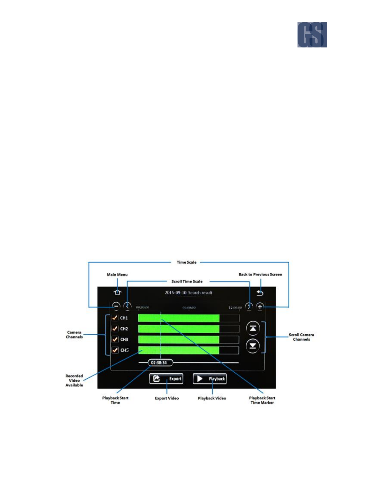
G4-304SD1 User Manual & Install Guide
50 of 149
Main Menu: Click this icon to return to the Main Menu.
Back to Previous Screen: Click this icon to return to the Previous Screen that you were at.
Video Type: Clicking the ( v ) button displays a drop down menu which allows you to select the
type of video to search for and retrieve.
All : All available video.
Normal : Normal video only (without any alarm events).
Alarm : Only videos with alarm events.
Select Camera Channels: Click to toggle select the camera channels to include. Selected camera
channels are marked with a red check. Recorded video will only be retrieved for playback from
the selected camera channels.
Search: After selecting the video type and camera channels, clicking on the ( Search ) button
will proceed to the playback screen for the recorded video.
REC Search Step 3: Selecting the Time Period
After the date and camera channels have been selected, the time period display screen allows you to
visualise easily (using a time bar) when recorded video data is available, and on which channels. You
may then select the time of interest from, as well as the specific camera channels, from which to
commence playback. The system also allows you to export a video clip of the specified time period.
Figure 5-5 REC Search Time Controls

G4-304SD1 User Manual & Install Guide
51 of 149
Main Menu: Click this icon to return to the Main Menu.
Back to Previous Screen: Click this icon to return to the Previous Screen that you were at.
Time Scale: This is the time bar which shows recorded video availability for the day (from
00:00:00H to 23:59:59H). Click the ( + ) and ( - ) buttons to zoom in and zoom out respectively.
Zooming in decreases the time scale, and zooming out increases the time scale – to allow for
easier visualisation and selection of time periods.
Scroll Time Scale: After zooming in, the entire day’s time scale will not be able to fit on the
screen display. Click the ( < ) and ( > ) buttons to scroll the time scale to the left and right
respectively.
Camera Channels: This shows the camera channels for which the recorded video is available.
Use the checkboxes to select/deselect the camera channels which are to be included in the
playback.
Scroll Camera Channels: When more than four camera channels have recorded video available,
click the ( ^ ) and ( v ) buttons to scroll up and down in the list of available channels.
Recorded Video Available: The colored bar shows the times for which recorded video is available.
The bar is colored coded to indicate the type of video available.
RED : Recorded video at this time period has alarm events.
YELLOW : Recorded video at this time period is locked.
GREEN : Normal recorded video at this time period.
Playback Start Time: This shows the selected playback time. Clicking on it will bring up the time
control dialog which allows you to key in a specific time (in hh:mm:ss 24-hour time format) from
which to begin the playback.
Playback Start Time Marker: This vertical blue dotted line indicates the playback start time across
the camera channels. If you are using a Finger Mouse or an ICD2, you can click and drag left
and right along the colored bars to quickly move the marker in order to select a different
playback start time.

G4-304SD1 User Manual & Install Guide
52 of 149
Playback Video: After selecting the playback start time and specifying the camera channels,
clicking ( Playback ) will proceed to the playback screen for the recorded video.
Export Video: Clicking the ( Export ) button will allow you to export the recorded video as a clip
from a specified start and end time.
REC Search Step 4: Playing the Recorded Video
If you are using a Finger Mouse, you can toggle the on-screen controls by pressing the Right Button,
whereas with the ICD2, you would just tap anywhere on the video. If there is no user input, then the onscreen playback controls will auto-hide after 15 seconds of inactivity.
If more than one camera channel was selected for playback during the previous step, all the
selected channels will be displayed in quad screen mode (2x2 grid layout). With a Finger Mouse
or ICD2, you can easily select a single channel to view in full screen by double-clicking on it.
Figure 5-6 REC Search Playback Controls
Selected Time Period: This time bar represents the selected time period.
Recorded Video Available: The green shaded areas in the time bar lets you easily identify where
the recorded video is available.
Slider Bar Knob: Using a Finger Mouse or an ICD2, you can click-and-drag this moveable knob
to the specific time where you wish to view the recorded video.
Audio Controls Toggle: This toggle button lets you show or hide the audio controls.

G4-304SD1 User Manual & Install Guide
53 of 149
Increase Volume: Increase the volume of the audio in the video recording currently being played
back.
Decrease Volume: Decrease the volume of the audio in the video recording currently being
played back.
Current Playback Time Control: This shows the current playback time. Clicking on it will bring
up the time control dialog which allows you to key in a specific time (in hh:mm:ss 24-hour time
format) from which to begin the playback.
Cycle to Next Channel: Switch playback to the next camera channel. For example, if the system
is currently playing recorded video from Camera 3, then clicking this button will switch to
playing recorded video from Camera 4.
Cycle to Previous Channel: Switch playback to the previous camera channel. For example, if the
system is currently playing recorded video from Camera 3, then clicking this button will switch
to playing recorded video from Camera 2.
Reverse Play: Clicking this button will cycle the reverse playback speed iteratively through the
following speed settings – 2x, 4x, 8x and 16x.
Play / Pause: Clicking this button will toggle the video between playback and pause. If the video
is playing in either fast forward or reverse play direction, then clicking this button will revert to
forward playback in real-time speed (1x).
Forward Play: Clicking this button will cycle the forward playback speed iteratively through the
following speed settings – 2x, 4x, 8x and 16x.
Slow Motion: Clicking this button will cycle the forward playback speed iteratively through the
following slow motion speed settings – 1/2x, 1/4x, 1/8 x and 1/16x.
Frame Step: This button allows the user to step through the recorded video frame by frame.
Exit Playback: Clicking this button returns you to the previous screen where you can select a
different time period for playback.

G4-304SD1 User Manual & Install Guide
54 of 149
REC Search Step 5: Exporting the Recorded Video
At the time period selection screen of the REC Search function, you may also choose to export a video
clip of the recorded video data by specifying a start and end time for the video and clicking the ( Export
) button on the screen. At any time, you may return to the previous screen by clicking ( ) or the (
Back ) button. You can also click the Home ( ) icon to return to the Main Menu.
How to Perform the Export Operation
Step 5.1
System will display the exporting selection screen as below.
Click the checkboxes to toggle select/deselect the camera channels to export from.
To export the entire day’s video, just click on the ( Export ) button.
A summary screen will be displayed showing the export time period (in this case, it
will be 00:00:00 to 23:59:59), and the estimated file size of the video clip data to be
exported.
The video clip data will be exported to the external storage medium USB flash drive
which is shown and selected on the screen. The system will only allow you to
proceed if the available space on the selected external storage medium must be
equal or more than the estimated file size.
Please Note: If you are using the Finger Mouse/LCD combination to navigate you
will need to use a Gatekeeper Systems USB Hub to allow two devices to share the
one USB port.
You will also need to select the file format that the exported video clip will be saved
as:
Proprietary Data : File format which is proprietary to the G4-304SD1.
Can only be viewed using the viewer software
provided by Gatekeeper Systems.
AVI Data : Standard AVI file format.
Can be viewed using any standard media player.
Click the ( Export ) button to proceed to clip and save the video data to the
specified external storage device.
If you wish to go back at any time to select a different time period, you may click
the ( Cancel ) button.

G4-304SD1 User Manual & Install Guide
55 of 149
Step 5.2
After selecting the camera channels, you can also specify the time period of the
video data that you wish to export.
Click on the Playback Start Time to key in the specific start time of the video that
you wish to export.
If you are using the Finger Mouse or the ICD2, you may also click and drag the
Playback Start Time Marker to the start time that you desire.
Click the ( Start Time ) button to register this as the desired start time. Your
selection will be displayed on the screen.
Next, select the desired end time by once again clicking on the time and keying in,
or moving the marker as before.
When your desired end time is displayed, click the ( End Time ) button to register
this.
Your selected end time will be displayed on the screen.
The system will calculate and display the estimated file size of the video clip for this
selected time period.
Click the ( Export ) button to proceed.
You may also click the ( Cancel ) button in order to go back and select a different
time period.
Gatekeeper Systems USB hub. Note the
instructions for the correct order in which
to connect devices.

G4-304SD1 User Manual & Install Guide
56 of 149
Step 5.3
Once you have selected both the camera channels and the time period, click the (
Export ) button to proceed.
A summary screen will be displayed showing the selected time period and the
estimated file size of the video clip data to be exported.
The video clip data will be exported to the external storage medium USB flash drive
which is shown and selected on the screen. The system will only allow you to
proceed if the available space on the selected external storage medium must be
equal or more than the estimated file size.
You will also need to select the file format that the exported video clip will be saved
as:
Proprietary Data : File format which is proprietary to the G4-304SD1.
Can only be viewed using the viewer software
provided by Gatekeeper Systems.
AVI Data : Standard AVI file format.
Can be viewed using any standard media player.
Click the ( Export ) button to proceed to clip and save the video data to the
specified external storage device.
If you wish to go back at any time to select a different time period, you may click
the ( Cancel ) button.
5.3 Using Log Search
The Log Search feature can be accessed from the Main Menu after logging in. It allows the user to
search for and view various operational logs. Users can also select and export the log files to an external
storage device (such as USB flash drive) for later viewing.
Please Note: If you are using the Finger Mouse/LCD combination to navigate you will need to use a
Gatekeeper Systems USB Hub to allow two devices to share the one USB port.
Log Search Step 1: Selecting the Date
The first step in the Log Search screen allows you to select a date to view the associated log files. It uses
a calendar view to enable the user to easily visualise the availability of log files for viewing.

G4-304SD1 User Manual & Install Guide
57 of 149
Figure 5-7 Log Search Date Controls
Main Menu: Click this icon to return to the Main Menu.
Back to Previous Screen: Click this icon to return to the Previous Screen that you were at.
Logs Available: A green bar below the date indicates that log files exist for that particular date.
Select Month: The ( ^ ) and ( v ) buttons allow you to scroll through and select the month.
Select Year: The ( ^ ) and ( v ) buttons allow you to scroll through and select the year.
Calendar View: The calendar shows the dates for the month and year which has been selected.
Clicking on the date of interest will select it.
Next Step: After selecting the date, clicking on the ( Next ) button will proceed to the camera
channel selection screen.
Log Search Step 2: Selecting the Time and Log Type
The next step in the Log Search function allows you to select the time period, and the type of log that
you wish to view.

G4-304SD1 User Manual & Install Guide
58 of 149
Figure 5-8 Log Time and Type Selection
Main Menu: Click this icon to return to the Main Menu.
Back to Previous Screen: Click this icon to return to the Previous Screen that you were at.
Select Time Period: Clicking on the Start Time field or the End Time field will display the on-
screen keypad which allows you to key in a specific time (in hh:mm:ss 24-hour time format).
Select Log Type: This allows you to select the type of log file to be displayed.
Alarm : Log file listing alarm events.
Operation : Log file listing operational events.
Locked : Log file listing locked events.
What are locked events?
The device setup allows you to configure the recording settings such that video is always
retained for a specified number of days after it is recorded. Locked video refers to recorded
video which falls within the stipulated duration, and hence is protected against being deleted
or overwritten by the device. Locked events are events for which the corresponding video is
still in locked mode.

G4-304SD1 User Manual & Install Guide
59 of 149
If the Alarm log type is selected, the log file can be filtered further by Alarm Type.
All : Show all alarm events.
IO Alarm : Only show IO alarm events.
Panel Alarm : Only show panel alarm events.
Speed Alarm : Only show speed alarm events.
Video Loss : Only show Video Loss events.
Next Step: After selecting the time and log type, clicking on the ( Search ) button will proceed
to display the log file data on the screen.
Log Search Step 3: View and Export the Log File
The final step in the Log Search function allows you to view the log file data and to export it to an
external storage device for archival or later study.
Figure 5-9 View and Export Log File
Main Menu: Click this icon to return to the Main Menu.
Back to Previous Screen: Click this icon to return to the Previous Screen that you were at.
Page Up/Down: The ( ^ ) and ( v ) buttons allow you to scroll the pages of the log data.
Jump to Page: Clicking on the field allows you to key in a specific page to immediately jump to.
Log Data: This is the log data sorted by time. Clicking on any log data item will show additional
details associated with the event (e.g. user name, etc.).
Video: If there is any video linked with this log item, clicking this icon will allow you to playback
the video for viewing.
Export: Clicking this icon allows you to export the log file to an external storage USB flash drive.

G4-304SD1 User Manual & Install Guide
60 of 149
6 Configuring the G4-304SD1
6.1 Quick Reference to Configuration Menu System
The following shows a high level map to the various settings in the G4-304SD1 configuration menu
system. Please refer to the following sections for a detailed description of each section.

G4-304SD1 User Manual & Install Guide
61 of 149
6.2 Navigating the Configuration Menus
The configuration menus are presented in a tabular format, where the main sections can be selected
from the row of tabs at the top of the screen. The subsections within each main section are arrayed in
columnar format, and can be selected from the column of page subsections on the left edge of the
screen. Within each subsection page, there may also be nested tabs for different pages of settings.
The Layout of the Configuration Menu System
Figure 6-1 Layout of the Configuration Menu
Main Menu: Click this icon to return to the Main Menu.
Back to Previous Screen: Click this icon to return to the Previous Screen that you were at.
Main Section Tabs: Clicking on any of these tabs will open the configuration pages for that
particular main section.
Subsection Pages: This the list of subsections which are contained within the main section.
Clicking on these will display the configuration settings related to this particular subsection.
Scroll Up: Click this button to scroll up in the list of subsections.
Scroll Down: Click this button to scroll down in the list of subsections.
Nested Sub Tabs in Page: Some subsection pages will also have nested sub tabs to further
subdivide the configuration settings. Click on the sub tab to open the related settings page.

G4-304SD1 User Manual & Install Guide
62 of 149
Scroll Page: Some pages will have many configuration settings that cannot be listed on the
screen all at once. The ( ^ ) and ( v ) buttons allow you to scroll up and down in order to access
all the settings available on the page.
Reset to Defaults: Click the ( Default ) button to reset the settings on the current page to the
factory defaults.
Save Changes: Click the ( Save ) button to save any changes that you have made to the settings
on the page.
If you navigate away from the current page/tab without saving, any changes that you
have made to the settings will be discarded.
Please note that your configuration settings have been set by Gatekeeper Systems
engineers to meet your specific deployment requirements. Do not reset to factory
defaults or change the settings unless you fully understand the changes you are
making, or as directed by Gatekeeper Systems.
Data Entry Interfaces of the Configuration Menu System
Component
Description
Button
Clicking any button will either perform an action, or advance you to
the next step in the process.
Checkbox
Checkboxes allow you to toggle an item – clicking on it will select it,
and clicking on a selected item will deselect it. If the checkbox is
checked (has a checkmark in the box), then the item next to the
checkbox is selected. An empty box (no checkmark) means the item is
not selected. Multiple selections are allowed.
Radio Button
Radio buttons allow you to make one selection from among a group
of choices. Clicking on the radio button will select it (marked circle).
Clicking on any other item in the group will select that item, and
unselect the first item. Only one item can be selected at a time.

G4-304SD1 User Manual & Install Guide
63 of 149
Text Field
This is a general field which accepts user input. Clicking the field will
display an on-screen full qwerty keyboard for the user to key in the
text (both alphabetical and numbers).
However, if the field will only accept numeric values, clicking on the
field will display an on-screen keypad for the user to key in numeric
values.
Date Field
This is an input field for dates. Clicking on this field will show a calendar
from which the user can select the desired date.
Time Field
This is an input field for time. Clicking on this field will show an onscreen keypad which the user can use to enter the time values.

G4-304SD1 User Manual & Install Guide
64 of 149
Drop List
This is a controlled input field which only accepts selections from a
predefined list of items. This kind of field can be identified by a ( v )
button to the right of the field. Clicking this button will display a list of
items which can be scrolled and selected.
6.3 Basic Settings
Navigate to: Main Menu Setup Basic Setup
All the core device settings can be configured in this section. This includes key operational
configurations such as device identifiers and vehicle information, user management, time setup, device
startup behaviour and communications setup such as network settings and FTP server configuration.

G4-304SD1 User Manual & Install Guide
65 of 149
Figure 6-2 Basic Setup Tab in the Device Configuration Options
6.3.1 Regist Info
Navigate to: Main Menu Setup Basic Setup Regist Info
This subsection enables you to view and set the various identification codes to be associated with the
device, as well as the vehicle it will be installed in, and the associated vehicle driver.
Device Info
Device ID
Numeric text field for setting a number to
identify the device.
You may input up to a maximum of:
5 digits
Note:
- This value is only set when the device is
configured as part of a Gatekeeper Wireless
deployment.
DEFAULT SETTINGS:
Please refer to Gatekeeper Project Team, in
consultation with customer/school district, for
the value to set.

G4-304SD1 User Manual & Install Guide
66 of 149
Vehicle Info
Vehicle Num
Alphanumeric text field for setting the vehicle
number. This is typically the identification code
used by the fleet operator to identify a
particular vehicle in the fleet.
You may input up to a maximum of:
10 characters
DEFAULT SETTINGS:
Please refer to Gatekeeper Project Team, in
consultation with customer/school district, for
the value to set.
Vehicle Plate
Alphanumeric text field for setting the vehicle
plate number. This is typically the vehicle
registration plate number.
You may input up to a maximum of:
10 characters
DEFAULT SETTINGS:
Please refer to Gatekeeper Project Team, in
consultation with customer/school district, for
the value to set.
Line Number
Alphanumeric text field for setting the vehicle
line number. This is typically the identification
code used by the fleet operator to identify a
particular route.
You may input up to a maximum of:
10 characters
DEFAULT SETTINGS:
Please refer to Gatekeeper Project Team, in
consultation with customer/school district, for
the value to set.
Driver Info
Driver Number
Alphanumeric text field for setting the driver
information. This could be the driver’s license
number or employee number.

G4-304SD1 User Manual & Install Guide
67 of 149
You may input up to a maximum of:
10 characters
DEFAULT SETTINGS:
Please refer to Gatekeeper Project Team, in
consultation with customer/school district, for
the value to set.
Driver Name
Alphanumeric text field for setting the name of
the driver.
You may input up to a maximum of:
10 characters
DEFAULT SETTINGS:
Please refer to Gatekeeper Project Team, in
consultation with customer/school district, for
the value to set.
6.3.2 Time Setup
Navigate to: Main Menu Setup Basic Setup Time Setup
The device contains a real time clock. This subsection enables you to view and set the date and time for
the device, and also configure the options used for time synchronization as well as daylight savings.
General
Date Format
Drop list which allows you to choose the format
in which date values will be displayed:
MONTH/DAY/YEAR
YEAR-MONTH-DAY
DAY/MONTH/YEAR
DEFAULT SETTINGS:
MONTH/DAY/YEAR
Time Format
Drop list which allows you to choose the format
in which time values will be displayed:
24 Hours
12 Hours

G4-304SD1 User Manual & Install Guide
68 of 149
DEFAULT SETTINGS:
24 Hours
Time Zone
Drop list which allows you to choose the time
zone that the device will be operating in.
DEFAULT SETTINGS:
(GMT-08:00) PACIFIC TIME (US &
CANADA)
If this is not your time zone, please change this
setting as appropriate to the actual time zone
that your fleet will be operating in.
Time Sync
Date/Time
This is a set of fields allowing you to set the
current date and time for the real time clock in
the device. It consists of the following fields:
Date field which enables you to set the
current date.
Time field which enables you to set the
current time.
Drop list which allows you to choose
AM/PM (only applicable if Time Format
is set to 12 Hours).
DEFAULT SETTINGS:
Please verify the time and date.
If the time and/or date is not correct, please
change them to the correct values.
Satellite
Checkbox – if selected, the device will
synchronize the date and time periodically with
the GPS satellites.
Note:
- This is the recommended setting to use
when the G4-304SD1 is deployed in a
mobile environment.
- To use this setting, the G4-304SD1 must be
equipped with the GPS option.
DEFAULT SETTINGS:
Checkbox – Selected

G4-304SD1 User Manual & Install Guide
69 of 149
Center Server
Checkbox – specifies if the device will
synchronize the date and time periodically with
the Center Server.
If this option is selected, you will also need to
use the associated drop list to specify which
Center Server will be used for the time
synchronization.
Note:
- This setting requires a constant network
connection either via cellular or WiFi.
DEFAULT SETTINGS:
Checkbox – Unselected
NTP Sync
Checkbox – specifies if the device will
synchronize the date and time periodically with
a selected Time Server.
If this option is selected, you will also need to
use the associated drop list to specify which
Time Server will be used for the time
synchronization.
Note:
- This setting requires a constant network
connection either via cellular or WiFi.
DEFAULT SETTINGS:
Checkbox – Unselected
DST
Enable
Checkbox – selecting this will enable the device
to calculate and adjust for daylight savings
time.
DEFAULT SETTINGS:
Checkbox – Selected
Offset
Drop list which allows you to choose the offset
value to be used for the daylight savings
calculation:

G4-304SD1 User Manual & Install Guide
70 of 149
One Hour (system will offset the time
by an hour when daylight savings is
active)
Two Hours (system will offset the time
by two hours when daylight savings is
active)
DEFAULT SETTINGS:
One Hour
Mode
Drop list which allows you to choose the mode
to be used for the daylight savings calculation:
Week (enable the system to activate
daylight savings based on a specified
day of the week in the year)
Date (set an actual hard date for when
daylight savings is active)
DEFAULT SETTINGS:
Week
Start
This is a set of fields which allow you to choose
the starting point of the period for which the
device will adjust for daylight savings time.
If the device is adjusting for daylight savings by
Week, you will need to specify the following:
Drop list to choose the start month
(from JAN to DEC).
Drop list to choose the start week
(either 1ST, 2ND, 3RD, 4TH or LAST).
Drop list to choose the start day (from
SUNDAY to SATURDAY).
Time field to choose the start time.
If the device is adjusting for daylight savings by
Date, you will need to specify the following:
Date field to set the start date.
Time field to set the start time.
DEFAULT SETTINGS:
MAR (month)
2ND (week)
SUNDAY (day)
02:00:00 (time)

G4-304SD1 User Manual & Install Guide
71 of 149
End
This is a set of fields which allow you to choose
the ending point of the period for which the
device will adjust for daylight savings time.
If the device is adjusting for daylight savings by
Week, you will need to specify the following:
Drop list to choose the end month
(from JAN to DEC).
Drop list to choose the end week
(either 1ST, 2ND, 3RD, 4TH or LAST).
Drop list to choose the end day (from
SUNDAY to SATURDAY).
Time field to choose the end time.
If the device is adjusting for daylight savings by
Date, you will need to specify the following:
Date field to set the end date.
Time field to set the end time.
DEFAULT SETTINGS:
NOV (month)
1ST (week)
SUNDAY (day)
02:00:00 (time)
6.3.3 Startup
Navigate to: Main Menu Setup Basic Setup Startup
This subsection enables you to set the startup characteristics of the device, as well behaviour of the
device whilst in sleep mode.
ON/OFF
ON/OFF Mode
Drop list to select the conditions for device
startup and shutdown:
Ignition – device will turn on when the
vehicle ignition is on, and turn off when
the vehicle ignition is off.
Timer – device will turn on following
the scheduled time, regardless of the
vehicle ignition status.
Ignition or Timer – device will start
either when vehicle ignition is on, or
when the scheduled time starts.

G4-304SD1 User Manual & Install Guide
72 of 149
However, the device will only turn off
when BOTH ignition is off AND
scheduled time ends.
DEFAULT SETTINGS:
Ignition
Ignition Delay
Numeric text field for setting the additional
time period that the device will continue
running after the vehicle ignition is off. The
device will only stop recording and shutdown
after this delay period is past.
DEFAULT SETTINGS:
300
This means that when the vehicle is turned off,
the device will continue to record for another
300 seconds (5 minutes) before shutting down.
Timer From
This consists of two time fields to set the start
time and end time for which the device will turn
on and turn off respectively.
DEFAULT SETTINGS:
Disabled/not applicable.
Sleep
Sleep Mode
Drop list to select the sleep mode option for the
device:
No Consumption Standby
Notes:
- Currently, this is the only option available.
DEFAULT SETTINGS:
No Consumption Standby
This means that the device will not be
consuming battery power when it is shut down.
Low Volt Protect
Checkbox – selecting this option will enable the
device to monitor battery voltage. If the battery
voltage falls below the specified threshold, the

G4-304SD1 User Manual & Install Guide
73 of 149
device will turn off to protect the battery from
being discharged.
DEFAULT SETTINGS:
Checkbox – Unselected
Battery Low Voltage
Protect
Numeric text field to set the battery low voltage
threshold. If Low Volt Protect is selected, the
device will turn off when battery voltage is
detected to be consistently below this
threshold value.
For a vehicle with a 12V battery, the
recommended threshold value is 9V. For a
vehicle with a 24V battery, the recommended
threshold value is 21V.
DEFAULT SETTINGS:
Disabled/not applicable.
Voltage Startup
Numeric text field to set the recovery boot
voltage threshold. When the vehicle battery
recovers its charge and is consistently above
this threshold value, the device will
automatically turn on again.
For a vehicle with a 12V battery, the
recommended threshold value is 12.5V. For a
vehicle with a 24V battery, the recommended
threshold value is 24.5V.
DEFAULT SETTINGS:
Disabled/not applicable.
Low Volt Upload
Checkbox – selected will enable the device to
log and report if low voltage situation occurs.
DEFAULT SETTINGS:
Checkbox – Unselected

G4-304SD1 User Manual & Install Guide
74 of 149
6.3.4 User Setup
Navigate to: Main Menu Setup Basic Setup User Setup
This subsection enables you to add and edit users, as well as change the passwords required to log into
the system.
User Setup
Idle Time
Drop list which allows you to set the login time
out period. Users will be automatically logged
out after the specified period of inactivity:
30 Seconds
1 Minute
3 Minutes
5 Minutes
10 Minutes
Never
DEFAULT SETTINGS:
3 Minutes
User Name / User Group
The User Name shows the list of users who are
set up in the system. The User Group shows the
type of user. Checkboxes next to the user
names allow you to select the specified user to
edit or delete.
Notes:
- The user admin is the default administrator
and cannot be deleted.
- Only administrators can add/delete users.
- In addition to the administrator, the
maximum number of additional users that
can be added is two.
DEFAULT SETTINGS:
Default administrator user
Username – admin
Password - admin
Default normal user
Username – user
Password - user

G4-304SD1 User Manual & Install Guide
75 of 149
Add
Button which displays the add user screen. On
the add user screen, the following fields will
allow you to key in the user details:
Alphanumeric text field to key in the
user name.
Alphanumeric text field to key in the
user password.
Alphanumeric text field to key in the
user password a second time in order
to confirm it.
For user name, you may input up to a maximum
of:
10 characters
For password, you may input up to a maximum
of:
16 characters
Delete
After using the checkbox to select a user, this
button will allow you to delete the selected
user. A confirmation message will be displayed
– clicking the ( Yes ) button on this prompt will
confirm the action and proceed to delete the
selected user from the device.
Edit
After using the checkbox to select a user, this
button will display the edit user screen. On the
edit user screen, the following fields will allow
you to modify the selected user’s details:
Alphanumeric text field to key in the
user name.
Alphanumeric text field to key in the
new user password.
Alphanumeric text field to key in the
new user password a second time in
order to confirm it.

G4-304SD1 User Manual & Install Guide
76 of 149
6.3.5 Network
Navigate to: Main Menu Setup Basic Setup Network
This subsection enables you to view and set up all the network configuration options for the device
communications. These include settings for the local network, web port settings, WiFi, communications
module, and center server settings.
Local
DHCP Mode
Checkbox – if selected, the device will attempt
to obtain the IP Address, Subnet Mask and
Gateway automatically from the DHCP server.
DEFAULT SETTINGS:
Checkbox – Unselected
Static IP
Checkbox – if selected, the device will use the
manually configured IP Address, Subnet Mask
and Gateway.
DEFAULT SETTINGS:
Checkbox – Selected
IP Address
Numeric text field allowing you to key in the IP
address for the device.
DEFAULT SETTINGS:
192.168.088.002
Subnet Mask
Numeric text field allowing you to key in the IP
address subnet mask for the device.
DEFAULT SETTINGS:
255.255.255.000
Gateway
Numeric text field allowing you to key in the IP
address of the gateway for the device.
DEFAULT SETTINGS:
192.168.088.001

G4-304SD1 User Manual & Install Guide
77 of 149
Auto Get DNS
Checkbox – if selected, the device will attempt
to obtain the DNS settings automatically.
DEFAULT SETTINGS:
Checkbox – Unselected
Use Following DNS
Checkbox – if selected, the device will use the
manually configured DNS settings.
DEFAULT SETTINGS:
Checkbox – Selected
Preferred DNS Server
Numeric text field allowing you to key in the IP
address of the primary DNS server.
DEFAULT SETTINGS:
192.168.001.001
Alternate DNS Server
Numeric text field allowing you to key in the IP
address of the alternate DNS server.
DEFAULT SETTINGS:
192.168.001.001
Ports
WEB Port
Numeric text field to set the web port number.
DEFAULT SETTINGS:
80
NOTE: THE FOLLOWING SECTION (WIFI) IS ONLY APPLICABLE FOR G4-304SD1S EQUIPPED WITH THE
INTERNAL WIFI MODULE. GATEKEEPER DOES NOT SUPPORT THIS CONFIGURATION.
WiFi
Enable
Drop list for selecting the WiFi option:
Disable
Client
DEFAULT SETTINGS:
Disable

G4-304SD1 User Manual & Install Guide
78 of 149
ESSID
Alphanumeric text field to enter the name of
the WiFi network.
DEFAULT SETTINGS:
Disabled/not applicable.
Encryption
Drop list to select the encryption setting of the
WiFi network:
None
WEP
WPA
DEFAULT SETTINGS:
Disabled/not applicable.
Password
Alphanumeric text field to key in the password
for the WiFi network. This is only applicable if
WEP or WPA is selected in the Encryption
settings.
DEFAULT SETTINGS:
Disabled/not applicable.
Static IP
Checkbox – if selected, the device will use the
manually configured IP Address, Subnet Mask
and Gateway. Else, it will attempt to
automatically obtain these values.
DEFAULT SETTINGS:
Disabled/not applicable.
IP Address
Numeric text field allowing you to key in the IP
address for the device.
DEFAULT SETTINGS:
Disabled/not applicable.
Subnet Mask
Numeric text field allowing you to key in the IP
address subnet mask for the device.
DEFAULT SETTINGS:
Disabled/not applicable.

G4-304SD1 User Manual & Install Guide
79 of 149
Gateway
Numeric text field allowing you to key in the IP
address of the gateway for the device.
DEFAULT SETTINGS:
Disabled/not applicable.
NOTE: THE FOLLOWING SECTION (COMM) IS ONLY APPLICABLE FOR G4-304SD1S EQUIPPED WITH
THE INTERNAL CELLULAR MODULE. GATEKEEPER DOES NOT SUPPORT THIS CONFIGURATION.
Comm
Module
Drop list which displays a list of connected
communication modules. Selecting one of
them will display the currently set configuration
values, and allow you to modify them.
These configuration values are module specific.
If you have more than one communications
module connected, you will need to select each
in turn and configure them separately.
DEFAULT SETTINGS:
Disabled/not applicable.
Server Type
This field is for display only. It automatically
displays the service type for the selected
module if it is connected to the service
provider. If not connected, then this field will
display “No Service”.
DEFAULT SETTINGS:
Disabled/not applicable.
Network Type
Drop list allowing you to select the network
type:
Mix
2G
3G
4G
DEFAULT SETTINGS:
Disabled/not applicable.
APN
Alphanumeric text field allowing you to
configure the APN value.

G4-304SD1 User Manual & Install Guide
80 of 149
DEFAULT SETTINGS:
Disabled/not applicable.
User Name
Alphanumeric text field allowing you to
configure the user name.
DEFAULT SETTINGS:
Disabled/not applicable.
Password
Alphanumeric text field allowing you to
configure the password.
DEFAULT SETTINGS:
Disabled/not applicable.
Number
Numeric text field allowing you to configure
the dial-up number.
DEFAULT SETTINGS:
Disabled/not applicable.
Certification
Drop list allowing you to configure the
authentication protocol:
CHAP
PAP
DEFAULT SETTINGS:
Disabled/not applicable.
Active Mode
Drop list allowing you to configure the active
mode settings:
Always
Phone/SMS
Sensor
DEFAULT SETTINGS:
Disabled/not applicable.
Number1
Reserved numeric text field.

G4-304SD1 User Manual & Install Guide
81 of 149
DEFAULT SETTINGS:
Disabled/not applicable.
Number2
Reserved numeric text field.
DEFAULT SETTINGS:
Disabled/not applicable.
Number3
Reserved numeric text field.
DEFAULT SETTINGS:
Disabled/not applicable.
NOTE: THE FOLLOWING SECTION (SERVER) IS ONLY APPLICABLE WHEN THE DEVICE IS BEING
CONFIGURED AS PART OF A GATEKEEPER WIRELESS DEPLOYMENT.
Server
Center Server
Drop list which displays a list of center servers
configured in the device. Selecting one of them
will display the currently set configuration
values, and allow you to modify them.
These configuration values are server specific. If
you have more than one center server set up,
you will need to select each in turn and
configure them separately.
Add – this button allows you to add a new
center server name and configure its settings.
Delete – this button deletes the selected center
server and its associated configuration settings.
Notes:
- You may add up to 5 center servers.
- Server 1 is the default center server and it
cannot be deleted.
DEFAULT SETTINGS:
Server 1
ON
Checkbox – selecting this will mark the selected
server as active.

G4-304SD1 User Manual & Install Guide
82 of 149
DEFAULT SETTINGS:
Checkbox – Selected
Protocol Type
Drop list to select the protocol type option for
the selected center server:
N9M
Notes:
- Currently, this is the only option available.
DEFAULT SETTINGS:
N9M
Enable Network
Drop list to select the network mode used to
communicate with the selected center server:
Local
WiFi – Not Supported
Module1 – Not Supported
Module2 – Not Supported
DEFAULT SETTINGS:
Local
Register Server Add
Numeric text field to configure the IP address
of the register server.
DEFAULT SETTINGS:
174.1.68.160
Register Port
Numeric text field to configure the port values
used by the register server for the following
protocol types:
TCP
UDP
DEFAULT SETTINGS:
TCP – 5556
UDP – 6222
Media Server IP
Numeric text field to configure the IP address
of the media server.

G4-304SD1 User Manual & Install Guide
83 of 149
DEFAULT SETTINGS:
174.1.68.160
Media Port
Numeric text field to configure the port values
used by the media server for the following
protocol types:
TCP
UDP
DEFAULT SETTINGS:
TCP – 8081
UDP – 6111
6.3.6 Application
Navigate to: Main Menu Setup Basic Setup Application
This subsection enables you to view and edit the application settings of the device, related to FTP and
traffic management.
NOTE: GATEKEEPER DOES NOT SUPPORT THIS CONFIGURATION.
FTP Server
FTP Enable
Checkbox – if selected, the device will use the
configured FTP settings.
DEFAULT SETTINGS:
Checkbox – Unselected
Server
Numeric text field for setting the IP address of
the FTP server.
DEFAULT SETTINGS:
Disabled/not applicable.
Port
Numeric text field to set the port number to
connect to on the FTP server.
DEFAULT SETTINGS:
Disabled/not applicable.

G4-304SD1 User Manual & Install Guide
84 of 149
User Name
Alphanumeric text field for setting the user
name to access the FTP server.
DEFAULT SETTINGS:
Disabled/not applicable.
Password
Alphanumeric text field for setting the user
password to access the FTP server.
DEFAULT SETTINGS:
Disabled/not applicable.
NOTE: GATEKEEPER DOES NOT SUPPORT THIS CONFIGURATION.
6.4 Surveillance Settings
Navigate to: Main Menu Setup Surveillance
This section allows the user to setup the Digital IP Camera, and also configure the on-screen display
and video capture and streaming settings for both the live viewing as well as the recording functions.
The settings here are crucial and will allow you to not only enable and disable cameras for
viewing and recording, but also configure timings for when recording actually takes place, and
adjust the resolution and quality of the recorded video.
Figure 6-3 Surveillance Tab in the Device Configuration Options

G4-304SD1 User Manual & Install Guide
85 of 149
6.4.1 Live View
Navigate to: Main Menu Setup Surveillance Live View
This subsection enables you to configure the settings for the live view of the video coming from the
cameras. These settings only affect the video being viewed on the LCD monitor or the ICD2 – they do
not affect the recorded video.
Preview
Preview
Audio
Checkbox – if selected, the audio stream will be played while during
the live video view. Else, the audio will be muted by default.
Nevertheless, the audio can still be toggled on and off from the video
viewing screen itself.
DEFAULT SETTINGS:
Checkbox – Selected
Image Setup
This button displays the image setup screen.
DEFAULT SETTINGS:
Please adjust the video from the various camera channels using the
settings explained below to meet your preferences.

G4-304SD1 User Manual & Install Guide
86 of 149
Image Setup Menu: The entire image setup menu is floating over the video from the live
camera. You may click and drag the entire image setup menu up and down in order to look
at different parts of the image.
Flip Horizontal: This button flips the entire camera video along the horizontal axis. This is
especially useful for cameras installed in upside-down orientation.
Flip Vertical: This button flips the entire camera video along the vertical axis.
Color Controls: The ( - ) and ( + ) buttons enable you to adjust the color values of the image.
You may also click and drag the respective slider bar knob to adjust the setting quickly. There
are 4 image color settings which can be adjusted.
BRI : Brightness
CON : Contrast
COL : Color Warmth
SAT : Color Saturation
Channel Being Configured: This drop list enables you to select a channel to configure. The
video from the selected channel will be displayed, and you will be able to adjust the settings.
Each channel can have specific settings, and you will need to adjust each in turn.
Copy To Channel: In multi-camera installations, this feature allows you to easily copy the
configuration of one camera channel to another channel, or even overwrite all channels with
the settings from the currently selected channel. Use the drop list to select the camera
channel that you wish to overwrite with the current settings.
Copy Settings: After selecting the camera channel that you wish to overwrite with the current
settings, clicking the ( Copy ) button will proceed to do so.
Revert to Defaults: Click the ( Default ) button to revert the settings to the factory defaults.
Save Settings: Click the ( Save ) button to save the settings to the currently selected camera
channel.
Exit this Menu: Click the ( Exit ) button to return to the previous screen. Please note that you
will lose any changes unless you first save the settings.
Margins
This button displays the margin setup screen which has the following
options:
Margin-top
Margin-bottom
Margin-left
Margin-right
You may use the ( + ) and ( - ) buttons or click and drag the slider knob
to adjust the margins of the screen to fit the display within the
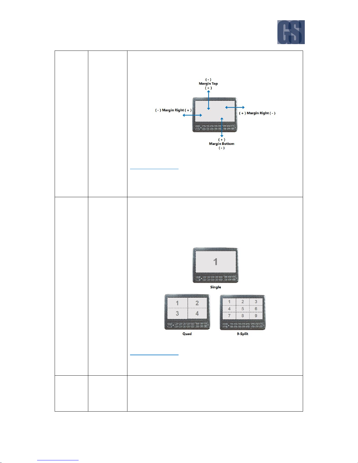
G4-304SD1 User Manual & Install Guide
87 of 149
limitations of your display monitor. This is especially useful if you find
that parts of the display are off-screen.
DEFAULT SETTINGS:
Please adjust the margins if necessary to ensure the entire screen fits
comfortably within your installed display monitor.
Startup
Screen
Drop box for selecting the type of live video displayed by default after
device startup:
Single
Quad
9-Split
DEFAULT SETTINGS:
Quad
Channel
Checkboxes – allows you to select the cameras to be included as part
of the live view displayed channels.
Notes:

G4-304SD1 User Manual & Install Guide
88 of 149
- You are allowed to select more display channels than there are
cameras available.
- However, the selected display channels which do not have cameras
will be displayed in the live view as a black box.
DEFAULT SETTINGS:
Checkbox – Channel 1 – Selected
Checkbox – Channel 2 – Selected
Checkbox – Channel 3 – Selected
Checkbox – Channel 4 – Selected
Checkbox – Channel 5 – Unselected
Auto Loop
Screen / Mode
/ Channel /
Duration
This displays a list of screen layouts which have been configured in the
device. If Auto-Loop is enabled, each of the screen layouts be displayed
for the specified duration, and the display will cycle iteratively and
repeatedly through the list of screen layouts.
Clicking the ( ) button will allow you to edit the settings of the
associated screen layout.
Mode: This enables you to choose the display mode, whether channels will be displayed in
single, quad or 9-split mode.

G4-304SD1 User Manual & Install Guide
89 of 149
1x1 : Single camera on the screen
2x2 : Four cameras on the screen in 2x2 (quad) grid layout
Channel: The drop lists are shown on-screen accordingly to the grid layout mode selected.
You can easily choose each individual camera channel to be displayed in the selected grid
segment visually. If you have less cameras than available grid segments, then those segments
associated with an actual camera will be displayed as a black box. The drop down list will
show for all connected cameras.
Duration: This numeric text field allows you to specify the duration (in seconds) for which this
layout will be displayed on the screen.
Save Settings: The ( OK ) button allows you to save the settings for this screen layout.
Back to Previous: The ( Cancel ) button allows you to return to the previous screen.
Add Screen
Clicking the ( Add Screen ) button will add a new screen layout to the
list. You can then use the ( ) button to edit the new screen layout
settings.
x Clicking the ( x ) button will delete the associated screen layout.
Auto Loop
Checkbox – if selected will enable the auto-loop feature.
DEFAULT SETTINGS:
Checkbox – Unselected
Live OSD
Date/Time
Checkbox – if selected, the date and time will be displayed as an overlay
text on top of the live video view on the LCD monitor or ICD2.
DEFAULT SETTINGS:
Checkbox – Selected
Vehicle Num
Checkbox – if selected, the vehicle number will be displayed as an
overlay text on top of the live video view on the LCD monitor or ICD2.
Notes:
- The Vehicle Num data which the device will display on the OSD is
actually the identifier data which is set in the Basic Setup Regist
Info Vehicle Info Vehicle Num.
DEFAULT SETTINGS:
Checkbox – Selected

G4-304SD1 User Manual & Install Guide
90 of 149
Alarm
Checkbox – if selected, any alarms will be displayed as an overlay text
on top of the live video view on the LCD monitor or ICD2.
DEFAULT SETTINGS:
Checkbox – Selected
Device ID
Checkbox – if selected, the device ID will be displayed as an overlay
text on top of the live video view on the LCD monitor or ICD2.
Notes:
- The Device ID data which the device will display on the OSD is
actually the identifier data which is set in the Basic Setup Regist
Info Vehicle Info Vehicle Plate.
DEFAULT SETTINGS:
Checkbox – Unselected
Speed
Checkbox – if selected, the speed will be displayed as an overlay text
on top of the live video view on the LCD monitor or ICD2.
DEFAULT SETTINGS:
Checkbox – Unselected
GPS
Checkbox – if selected, the GPS coordinates will be displayed as an
overlay text on top of the live video view on the LCD monitor or ICD2.
DEFAULT SETTINGS:
Checkbox – Selected
Channel
Name
Checkbox – if selected, the channel name will be displayed as an
overlay text on top of the live video view on the LCD monitor or ICD2.
DEFAULT SETTINGS:
Checkbox – Unselected
ACC Info
Checkbox – if selected, the ACC information will be displayed as an
overlay text on top of the live video view on the LCD monitor or ICD2.
DEFAULT SETTINGS:
Checkbox – Unselected

G4-304SD1 User Manual & Install Guide
91 of 149
6.4.2 Record
Navigate to: Main Menu Setup Surveillance Record
This subsection enables you to configure the settings related to the video being recorded from the
various cameras.
General
System
This drop list enables you to select what system
format the video will be recorded in:
PAL
NTSC
DEFAULT SETTINGS:
NTSC
Overwrite
The device records video cyclically. This drop
list enables you to specify the conditions
whereby older video will be overwritten:
By Days – video older than a specified
number of days will be overwritten by
newer video. Selecting this will enable
a numeric text field where you can
specify the number of days to keep
video retained before overwriting.
By Capacity – video will be retained as
long as storage capacity is available. As
device storage capacity runs out, older
video data will be overwritten by newer
video data in First In First Out (FIFO)
format.
Never – video will never be
overwritten. In order to ensure that the
device still has storage to record new
video, you will have to download and
remove the older video on a regular
basis.
DEFAULT SETTINGS:
By Capacity
Lock Duration
Numeric text field setting the lock duration for
video data. If the lock duration is set, then video
will always be retained for at least this duration
regardless of the Overwrite settings.

G4-304SD1 User Manual & Install Guide
92 of 149
DEFAULT SETTINGS:
7 days
Pre-Recording
Checkbox – if selected will enable the prerecording feature, so that when alarms/events
occur, video data leading up to the incident is
available as well.
Selecting this checkbox will enable a drop list
where you can specify the duration of video to
pre-record.
DEFAULT SETTINGS:
Checkbox – Unselected
Main Stream
Channel
Drop list which displays the list of available
camera channels. Selecting one of them will
display the currently set configuration values,
and allow you to modify them.
These configuration values are channel specific.
You will need to select each channel in turn and
configure them separately.
Notes:
- For quick configuration, the copy function
allows you to easily copy the settings of the
current channel to another channel.
Channel Name
Alphanumeric text field for setting the channel
name. This is useful for giving the channel an
easily remembered and/or location-specific
name.
You may input up to a maximum of:
5 characters
Notes:
- Channels 1 to 4 are analog channels.
- Channel 5 is a Digital IP camera channel.
DEFAULT SETTINGS:
Channel 1 – set name as – CH1
Channel 2 – set name as – CH2

G4-304SD1 User Manual & Install Guide
93 of 149
Channel 3 – set name as – CH3
Channel 4 – set name as – CH4
Channel 5 – set name as – CH5
Enable
Checkbox – if selected, enables this channel for
inclusion into the main stream recording.
DEFAULT SETTINGS:
For channels 1 to 5, only enable the channels
which actually have cameras connected. Please
note that the system will show a videoloss
message on channels which are enabled, but
do not have a connected camera (i.e., no
incoming video stream).
Resolution
Drop list for selecting the resolution to record
the video on this channel (applicable to
channels 1 to 4 ):
CIF (352x240)
WCIF (464x240)
HD1 (704x240)
WHD1 (928x240)
D1 (704x480)
WD1 (928x480)
For the Digital IP Camera, 5, the drop list
contents will change to reflect the supported
resolutions of the currently attached IP camera.
Most commonly, these will typically be:
720P (1280x720)
DEFAULT SETTINGS:
For channels 1 to 4 (analog camera channels),
set the following:
D1
For channelXXX 5 (IP camera channel), set the
following:
720P
Frame Rate
Drop list allowing you to select the frame rate
(in terms of frames per second) that you would
like to record at.
DEFAULT SETTINGS:
For all channels (1 to 5), set the following:

G4-304SD1 User Manual & Install Guide
94 of 149
15
Quality
Drop list allowing you to select the encoding
quality (on a scale of 1 to 8 – where 1 is best).
DEFAULT SETTINGS:
For all channels (1 to 5), set the following:
1 (Best)
Record Mode
Drop list allowing you to select the record
mode:
Power Up – device will record
whenever it is powered on.
Timer – device will record following
the configured schedule.
Alarm – device will record whenever
there is an alarm event detected.
If the Record Mode selected is Timer, then a (
Schedule ) button will be enabled. Click this
button to display the schedule management
screen where you will be able to perform the
following functions:
Add a Plan – use the drop list to select
a day of the week (from Sunday to
Saturday). Clicking the ( Add a Plan )
button will then add a timer recording
schedule to the task list.
Start Time – this is a time field which
allows you to set the starting time to
begin the recording.
End Time – this is a time field which
allows you to set the ending time to
stop the recording.
Video Type – this is a drop list which
allows you to select the type of video
to be record (either Normal video, or
Alarm video only).
x – you can always click the (x) button
to remove the associated recording
task from the list.
Copy To – this feature allows you to
copy the current timer recording
settings scheduled for any particular
day to another day, thus allowing you
to easily and quickly replicate the timer
recording schedule settings. Once you

G4-304SD1 User Manual & Install Guide
95 of 149
have selected the day to copy to, click
on the ( Copy ) button to make the
copy.
DEFAULT SETTINGS:
For all channels (1 to 5), set the following:
Power Up
Audio
Checkbox – if selected, then audio will be
included in the recording. If this is not selected,
then the video will not have any audio,
DEFAULT SETTINGS:
For all channels (1 to 5), set the following:
Checkbox – Selected
Alarm Quality
Drop list to select the recording video quality
during an alarm event (on a scale of 1 to 8
where 1 is best).
DEFAULT SETTINGS:
For all channels (1 to 5), set the following:
1 (Best)
Encode Mode
Drop list to select the encoding mode to use:
CBR (Constant Bit Rate)
VBR (Variable Bit Rate)
The CBR settings instructs the device to encode
the video using a constant bit rate, thus
ensuring consistent quality and predictable file
size of the recorded video. When using VBR, the
device will vary the bit rate according to the
level of detail in the video at each given point
in time, thus attempting to optimise quality
against file size.
However, for critical video (where detail must
not be lost), and which also has a lot of fast
movement, CBR is the better choice, as VBR
would tend to introduce motion artifacts
(jaggedness and blurriness) into the encoded
video as the encoder attempts to keep up with

G4-304SD1 User Manual & Install Guide
96 of 149
the quick changing video scenes by
continuously adjusting the bit rate.
For optimal recorded video quality, Gatekeeper
Systems recommends the use of the CBR
setting throughout.
DEFAULT SETTINGS:
For all channels (1 to 5), set the following:
CBR
Copy
This feature allows you to easily copy the
configuration settings on this channel to
another selected channel. Use the drop list to
select a channel – then clicking the ( Copy )
button will replicate all the current settings to
the selected channel.
Dual Stream
Record Storage
Radio buttons that allow you to select the dual
stream record storage from a choice of:
Internal SD
External SD
Internal SD records to the formatted SD card
inserted to the device.
The External SD storage can be an SD Card
which is inserted into the device via USB.
Gatekeeper Systems provides a ruggedized
external SD accessory called FireBox, which is
shock and fire-resistant, to keep a copy of your
data safe in case of a vehicle crash or other
catastrophic event, so that video of the incident
can be retrieved for post mortem analysis.
Please contact your Gatekeeper Systems sales
representative for more details.
DEFAULT SETTINGS:
Internal SD
Record Mode
Drop list where you can select the dual stream
record mode:

G4-304SD1 User Manual & Install Guide
97 of 149
Sub Record – record a copy of the
video from selected channels to the
specified secondary storage, at a
separately configured (usually lower)
resolution and quality.
Mirror Record – record a copy of the
video from selected channels to the
specified secondary storage, using the
same resolution and quality as the
main recording.
Alarm Backup – record only the
alarm-triggered video to the specified
secondary storage.
None – Use this setting for sequential
recording. If two SD cards are inserted
into the G4-304SD1, once card 1 is full
of data card two will begin recording.
Please note that approximately 15
seconds of identical video will be on
both sd cards during the transition
from card 1 to card 2.
DEFAULT SETTINGS:
Mirror Record
Notes on Record Mode –
Sub Record
If the Record Mode is set to Sub Record, then
you may click on the ( Setup ) button to
configure the quality and resolution of the
recorded video to be stored to the secondary
storage. This configuration needs to be done
for each individual camera channel.
The following options will be on the Substream
Setup screen:
Channel – drop list to select the
particular channel to configure. When
a channel is selected, the
corresponding recording settings for
that channel will be displayed for
viewing and editing.
Enable – checkbox, if selected, would
enable the substream recording for
this channel. If unselected, would mean
that video from this channel would not
be recorded and stored as part of the
substream.
Audio – checkbox, if selected, would
include audio into the recording. If

G4-304SD1 User Manual & Install Guide
98 of 149
unselected, there would be no audio
recorded for this channel.
Resolution – drop list to select the
resolution to record this channel at.
Available resolution options are QCIF
(176x120), CIF (352x240), HD1
(704x240) and D1 (704x480).
Frame Rate – drop list allowing you to
select the frame rate (in terms of
frames per second) that you would like
to record at.
Quality – drop list allowing you to
select the encoding quality (on a scale
of 1 to 8 – where 1 is best).
Copy To – this feature allows you to
copy the current channel’s substream
recording settings directly to another
channel, thus allowing you to easily
and quickly replicate the substream
recording settings across channels.
Once you have selected the channel to
copy to, click on the ( Copy ) button to
make the copy.
Copy – click this button to copy the
current settings to the selected
channel.
OK – click this button to save the
current settings for the channel.
Cancel – click this button to exit back
to the previous screen without saving.
DEFAULT SETTINGS:
For all channels (1 to 5), set the following:
Enable – Checkbox – Selected
Audio – Checkbox – Selected
Resolution – CIF
Frame Rate – 15
Quality – 3
Mirror CH
Checkbox – select each checkbox to include the
associated camera channel into the dual stream
recording.
DEFAULT SETTINGS:
For channels 1 to 4 (analog camera channels),
set the following:
Checkbox - Selected

G4-304SD1 User Manual & Install Guide
99 of 149
For channel 5 (IP camera channel), set the
following:
Checkbox - Unselected
OSD
Date/Time
Checkbox – if selected, the date and time will
be displayed as an overlay text on top of the
recorded video.
DEFAULT SETTINGS:
Checkbox – Selected
Vehicle Num
Checkbox – if selected, the vehicle number will
be displayed as an overlay text on top of the
recorded video.
Notes:
- The Vehicle Num data which the device will
overlay into the recorded video is actually
the identifier data which is set in the Basic
Setup Regist Info Vehicle Info
Vehicle Num.
DEFAULT SETTINGS:
Checkbox – Selected
Channel Name
Checkbox – if selected, the channel name will
be displayed as an overlay text on top of the
recorded video.
DEFAULT SETTINGS:
Checkbox – Unselected
Speed
Checkbox – if selected, the speed will be
displayed as an overlay text on top of the
recorded video.
DEFAULT SETTINGS:
Checkbox – Selected

G4-304SD1 User Manual & Install Guide
100 of 149
GPS
Checkbox – if selected, the GPS coordinates will
be displayed as an overlay text on top of the
recorded video.
DEFAULT SETTINGS:
Checkbox – Selected
Device ID
Checkbox – if selected, the device ID will be
displayed as an overlay text on top of the
recorded video.
Notes:
- The Device ID data which the device will
overlay into the recorded video is actually
the identifier data which is set in the Basic
Setup Regist Info Vehicle Info
Vehicle Plate.
DEFAULT SETTINGS:
Checkbox – Unselected
Position
This setting allows you to customise the
location of the text data overlaid on the
recorded video. Click the ( Setup ) button to
display the position setting screen.
Notes:
- The text position can only be adjusted using
either a Finger Mouse or an ICD2.
DEFAULT SETTINGS:
Refer to Gatekeeper Project Team, in
consultation with customer/school district, for
the preferred positions of the text data.
 Loading...