

Mobility Manager User Manual
E65500

INSTRUCTION TO THE USER
This equipment has been tested and found to comply with the limits for a class B
digital device, pursuant to part 15 of the FCC rules. These limits are designed to
provide reasonable protection against harmful interference in a typical installation.
This equipment generates, uses and can radiate radio frequency energy and if
not installed and used in accordance with the instructions, may cause harmful
interference to radio communications. However, there is no guarantee that
interference will not occur in a particular installation. If this equipment does
cause harmful interference to radio or television reception, which can be
determined by turning the equipment off and on, the user is encouraged to try to
correct the interference by one or more of the following measures:
Reorient or relocate the receiving antenna on the device experiencing the
interference
Increase the separation between the Mobility Manager and the equipment
experiencing the interference.
Connect the equipment into an outlet on a circuit different from that to
which the Mobility Manager is connected
Consult the dealer or experienced technician for the device experiencing
the interference
In order to maintain compliance with FCC regulations, no changes can be made
to this equipment without the approval of Gatekeeper Systems, Inc. The user is
cautioned that any changes or modifications made to the equipment without the
approval of Gatekeeper Systems, Inc. could void the user’s authority to operate
this equipment.
Operation is subject to the following two conditions: (1) this device may not cause
interference, and (2) this device must accept any interference, including
interference that may cause undesired operation of the device.
This Class B digital apparatus complies with Canadian ICES-003.
Cet appareil numérique de la classe B est conforme à la norme NMB-003 du
Canada.
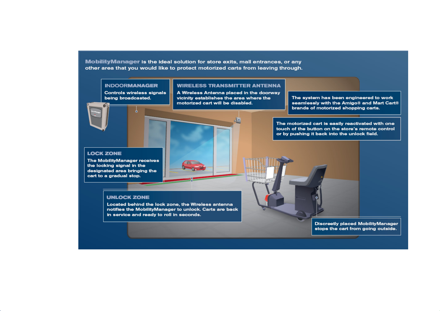
Mobility Operation Diagram:
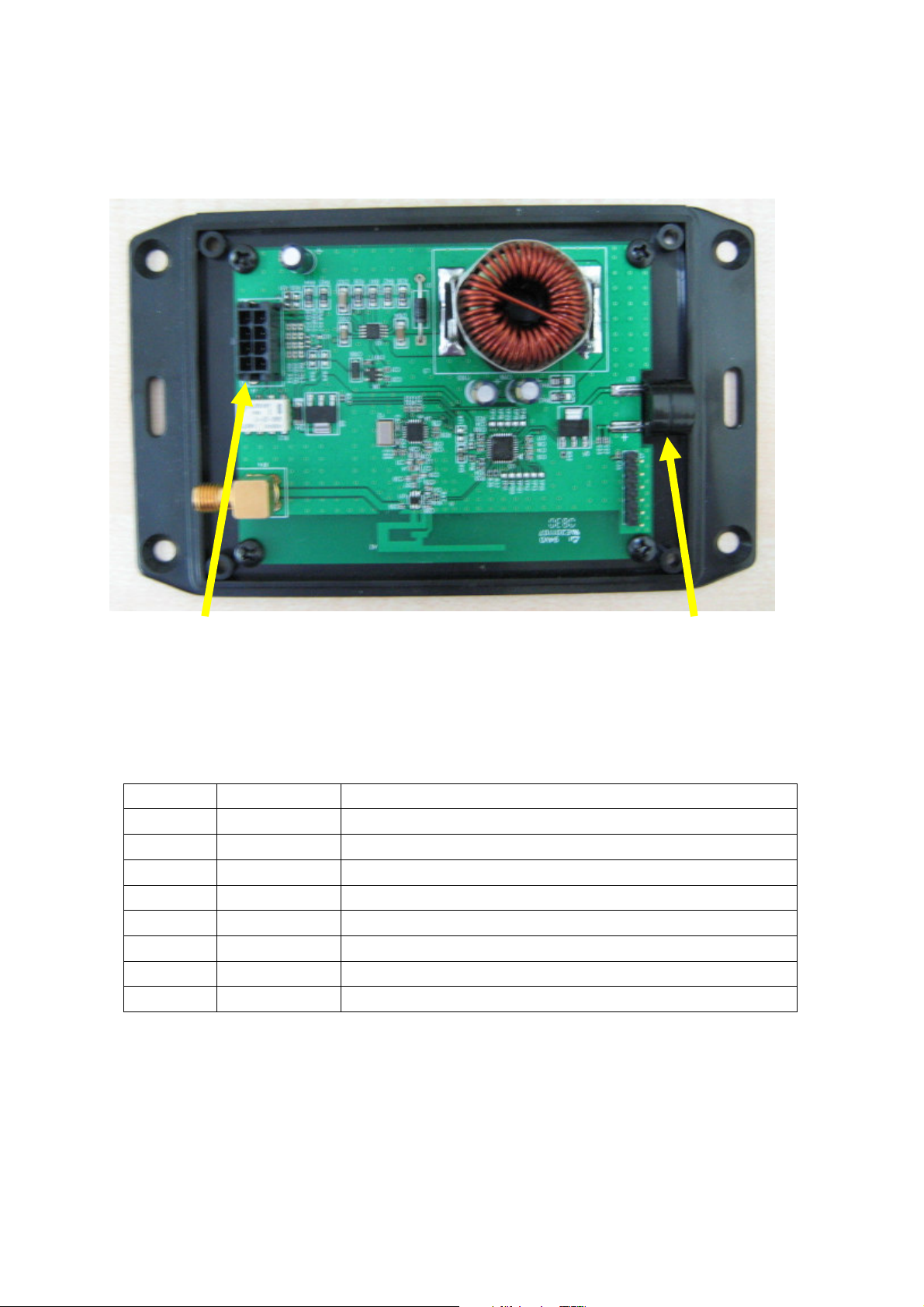
Terminal Block Alarm Buzzer
Power up Mobility Manager, by providing +12V DC power supply at terminal block pin
15 and grounding at terminal pin 1.
While power up, the Alarm buzzer will sound once to indicate Mobility in operating mode.
Terminal Block Definitions
Pin Name Description
1 Ground Ground
2 Ground Power Ground
3 Op Amp+ Amplifier +
4 LOCK_NC Lock Control (Max 24V)
5 +12VDC +12V DC Power input
6 DC Power 5V or 3V DC power
7 Op Amp- Amplifier 8 LOCK_COM Lock Control (Max 24V)

Contacting Gatekeeper Systems
For more information about the Mobility Manager and troubleshooting, to order parts or
report an issue, contact the Gatekeeper Systems Inc. regional Customer Support office
nearest to your location.
Hong Kong
Gatekeeper Systems (HK), Ltd.
Unit 2318~2319, Level 23, Tower 1, Metroplaza
NO. 223 Hing Fong Road, Kwai Fong, N.T.,
HONG KONG
(852) 2413 3050
USA
Gatekeeper Systems, Inc.
8 Studebaker
Irvine, CA 92618
(888) 808-9433
Canada
Gatekeeper Systems Canada, Ltd.
272 Galaxy Boulevard
Etobicoke, Ontario
Canada
M9W 5R8
(888) 525-3564
All Other Areas
Gatekeeper Systems SAS
58 rue de Neuilly
Parc des Guillaumes
93130 Noisy Le Sec
France
+33 1 48 54 76 78
 Loading...