


Safety, Security, Peace of Mind
NiTRO 900 Manual Version 1.8.1
-1-

Contents
Before You Begin...................................................................................................................................................5
Important Safeguards and Warnings. 6
Introduction. 6
System Overview....................................................................................................................................................8
Check List. 8
Main System. 8
Front Panel. 9
Rear Panel. 10
comrad™. 12
comrad™ Extraction. 12
Installation...............................................................................................................................................................13
Ten Steps for Installers. 13
Recommended System Locations. 13
Mounting the System. 14
Recommended Location for the IR Illuminator. 14
Recommended Location for Alarm Button. 15
Recommended Location for Record LED. 15
Routing the Power Harness. 15
Routing the Camera Harness(es). 16
Routing the Sensor Harness. 16
Installing the Dome Camera. 17
Bulkhead Mount. 17
Focusing Camera Lens. 18
Adjusting the Field of View. 18
Changing Camera Lens. 18
Check For: 19
Quick Configuration Settings for Installers. 20
Setting the Configuration...............................................................................................................................21
Basic Configuration. 21
Advanced Configuration. 24
System Configuration. 29
Recording................................................................................................................................................................32
Start Recording. 32
Stop Recording. 33
Playback from Recorder.................................................................................................................................33
Playback Methods. 33
Rew & Fwd Buttons. 34
Index Button. 34
Mark & Save. 35
Save 10 minutes. 35
System Shutdown...............................................................................................................................................36
Downloading Video.............................................................................................................................................36
comrad™ Only to Computer. 37
Manually Installing MAXVIEW™. 38
Connecting the Recorder to Computer with USB Ethernet Adaptor. 38
Browsing the Recorder on a Computer. 39
Recorder to Local Area Network (LAN). 39
MAXVIEW™...........................................................................................................................................................41
PC Requirements. 41
Installation. 41
Connect comrad™ to Computer via USB. 42
Operation. 44
Opening Video Files. 44
GPS. 45
Using The GPS Zoom Feature. 45
Using The Scrubber. 46
Time Graph Selection. 46
-2-

Using The Calendar Feature. 46
Audio Controls. 47
Displaying Sensors. 47
Drag and Drop a Video File. 48
Mark & Save a Video Clip. 48
Extracting Still Image. 48
Setting the Recorder Configuration. 49
Saving Configuration. 52
Loading Configuration on Recorder. 52
Check for Updates.. 52
Upgrading Software on the NiTRO™ 900. ..........................................................................................54
Troubleshooting...................................................................................................................................................55
Setting The System ID 56
Main Power Harness. 56
Sensor Harness Cable (CAB000145) 57
Notes. ........................................................................................................................................................................58
Warranty.................................................................................................................................................................61
Contact Information..........................................................................................................................................62
NiTRO 900 Manual Version 1.8.1
-3-

Table of Figures.
Figure 1: Front Panel. ........................................................................................................................................................................................................................9
Figure 2: Rear Panel. ..................................................................................................................................................................................................................... 10
Figure 3: Power Input – Pin-outs. ............................................................................................................................................................................................ 11
Figure 4: Sensor Input – Pin-outs. .......................................................................................................................................................................................... 11
Figure 5: comrad™ - Front and Rear Panels..................................................................................................................................................................... 12
Figure 6: comrad™ Extraction. ................................................................................................................................................................................................. 12
Figure 7: Recommended System Locations...................................................................................................................................................................... 13
Figure 8: IR20, Camera Location and Wiring................................................................................................................................................................... 14
Figure 9: Alarm Button/Record LED Splice...................................................................................................................................................................... 15
Figure 10: Removing Outer and Polycarbonate Dome. ...............................................................................................................................................17
Figure 11: Camera Seat Position............................................................................................................................................................................................ 17
Figure 12: Mounting the Camera. .......................................................................................................................................................................................... 17
Figure 13: Focusing The Camera............................................................................................................................................................................................ 18
Figure 14: Camera Seat Position............................................................................................................................................................................................ 18
Figure 15: Three Camera Configuration. ............................................................................................................................................................................ 19
Figure 16: Four Camera Configuration. ............................................................................................................................................................................... 19
Figure 17: Alternate Four Camera Configuration. ......................................................................................................................................................... 19
Figure 18: Cloning a comrad™................................................................................................................................................................................................. 32
Figure 19: Record Screen. ......................................................................................................................................................................................................... 33
Figure 20: Playback Display. ...................................................................................................................................................................................................... 34
Figure 21: Downloading Clips To A comrad™. ................................................................................................................................................................. 35
Figure 22: comrad™ Removal. .................................................................................................................................................................................................37
Figure 23: comrad™ to PC via USB.......................................................................................................................................................................................37
Figure 24: Manually Installing MAXVIEW™........................................................................................................................................................................ 38
Figure 25: Browsing The Recorder On A Computer..................................................................................................................................................... 39
Figure 26: Recorder To Local Area Network.................................................................................................................................................................... 40
Figure 27: MAXVIEW™ Operation.......................................................................................................................................................................................... 44
Figure 28: Composite of Map; Satellite and Hybrid Views.......................................................................................................................................... 45
Figure 29: Displaying The GPS Map. ..................................................................................................................................................................................... 45
Figure 30: Displaying The GPS Vehicle Locator............................................................................................................................................................... 45
Figure 31: Using the Calendar Feature. ..............................................................................................................................................................................46
Figure 32: Adjusting Playback Speed. ................................................................................................................................................................................... 47
Figure 33: Adjusting Sound Balance In Windows XP. .................................................................................................................................................. 47
Figure 34: Mark and Save Clips. .............................................................................................................................................................................................. 48
Figure 35: Save A Still Image..................................................................................................................................................................................................... 49
Figure 36: Upgrading Software................................................................................................................................................................................................ 54
-4-
A useful suggestion or tip for the advantage of the reader
Before You B
Before You Begin
Before You BBefore You B
In this document, important information is displayed using the following symbols:
egin....
eginegin
Alerts the reader that not adhering to the instruction could result
in bodily harm, equipment damage or data loss
Alerts the reader to a strong recommendation that will enhance
the performance of the recorder
Alerts the reader to refer to a section of the manual that will aid
in further explanation of the topic at hand
-5-
CAUTION
CAUTIONCAUTION
CAUTION
Important Safeguards and Warnings
Important Safeguards and Warnings....
Important Safeguards and WarningsImportant Safeguards and Warnings
Remove Main Power Fuse Prior To Any Electrical Work Or Jump Starting The Bus.
Remove Main Power Fuse Prior To Any Electrical Work Or Jump Starting The Bus.
Remove Main Power Fuse Prior To Any Electrical Work Or Jump Starting The Bus.Remove Main Power Fuse Prior To Any Electrical Work Or Jump Starting The Bus.
Connect 12V constant directly to the battery.
Connect 12V constant directly to the battery.
Connect 12V constant directly to the battery.Connect 12V constant directly to the battery.
The NiTRO™ 900 intended for indoor use; keep away from water and moisture.
The NiTRO™ 900 must be mounted more than two feet away from any two-way radio equipment. Do not mount
the NiTRO™ 900 near a heat source and do not block vents on the enclosure.
RISK OF ELECTRIC
SHOCK.
DO NOT OPEN
Do not remove the comrad™ from the NiTRO™ 900 system until the system has fully powered down. To
ensure that the system has fully powered down, check that the comrad™ power light is off.
The NiTRO™ System is incompatible with GSX System. Do not plug the GSX comrad™ to the front of the
NiTRO™ System or plug the NiTRO™ comrad™ to the front of the GSX System either physically or by USB.
Do not remove the cover of the NiTRO™ 900. Doing so will directly result in voiding the manufacturer’s
warranty. If your NiTRO™ 900 requires repair, contact Gatekeeper Systems Inc. (GSI) at 1.888.666.4833.
The NiTRO™ System power negative cable should be connected to a solid chassis grounding area, or, negative
post of battery.
All unused cables, sensor/indicator wires should be individually insulated, tied off and protected from touching
ground. Unused NiTRO™ cabling should never be grounded.
Introduction
Introduction....
IntroductionIntroduction
Congratulations on your purchase of the NiTRO™ 900 Digital Smart Recorder™ from Gatekeeper Systems Inc. Prior to
installing or using the NiTRO™ 900, please read this manual in its entirety in order to fully understand the correct
procedures for installation, setup and operation of the system.
The NiTRO™ 900 Digital Smart Recorder™ has been designed specifically to be a user friendly and cost-effective
replacement for conventional VHS analog recorders currently used in the industry.
Navigation through user menus is made simple through the use of the front panel mounted LCD screen which also
eliminates the need for a PC interface during setup. The NiTRO™ 900 Digital Smart Recorder™ is a simple and efficient
method for capturing video onboard your school buses.
-6-

The advanced digital recording technology of the NiTRO™ 900 eliminates the need for tape management and replacement
while offering:
Video management with MAXVIEW
comrad™ portable, vandal resistant hard drive and storage device
Isolation Suspension System
Thermal Intelligence™
Direct Connect USB 2.0
Power Guard
Smart Flag™ Alarm Verification
LCD Smart Search™ User-friendly and convenient way to find important images and clips
Substantial storage capability without compromising video quality
Accelerated download speeds
User friendly, intuitive design for easy operation and administration
Plus many more features
TM
video management system
-7-
Dome Camera(s)
System
System Overview
System System
Check List
Check List....
Check ListCheck List
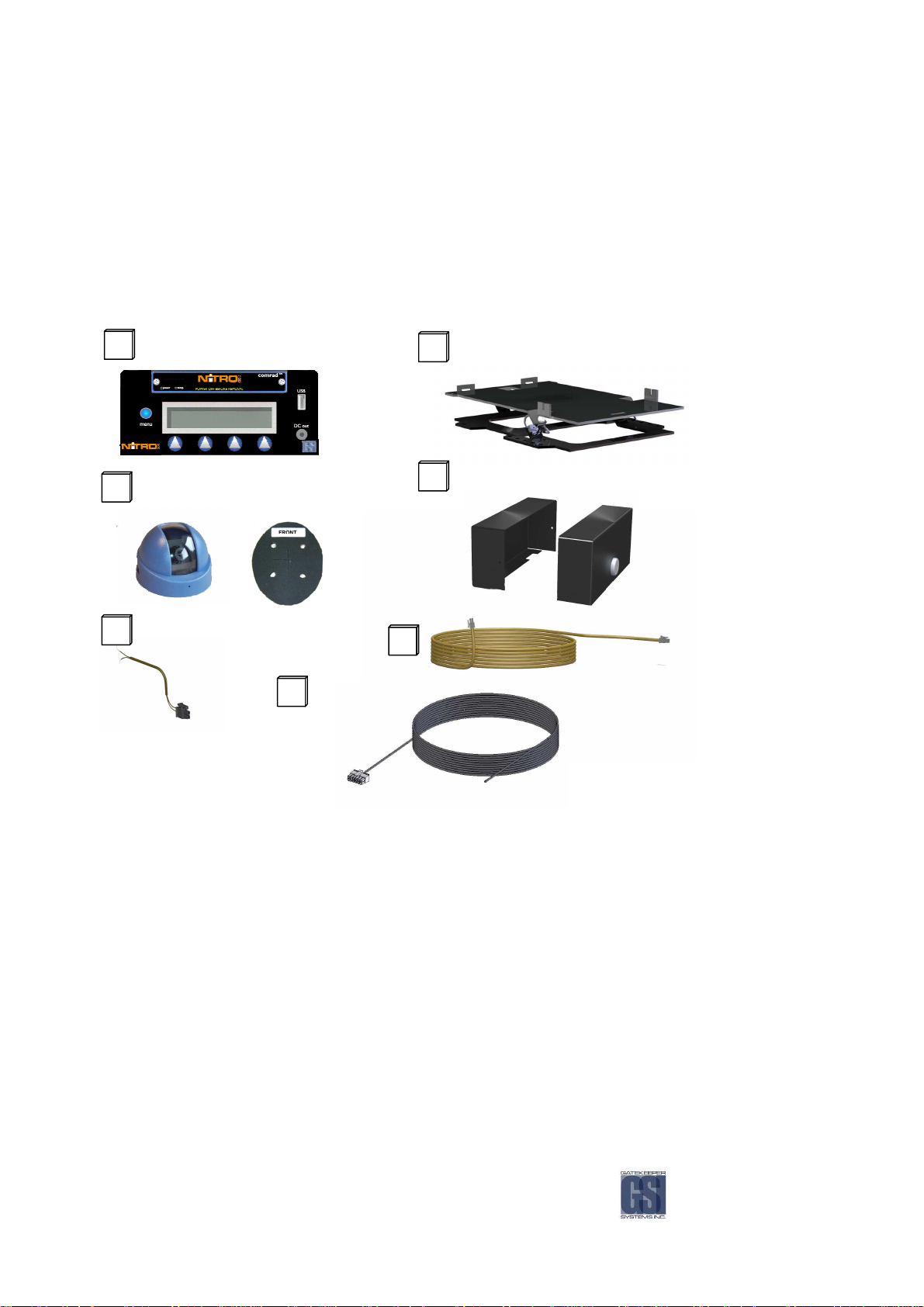
Use the provided check list to ensure that you have received all the components required for your complete NiTRO™ 900
Digital Smart Recorder.
Main System
Main System....
Main SystemMain System
If you have failed to receive any of the above parts please contact your dealer or GSI directly at 1.888.666.4833.
Overview....
OverviewOverview
NiTRO 900 Digital Smart Recorder
GSX-N900Control/GSX-N900comradXXX
System Color May Be Different To Tha t Shown.
Power Harness
CAB000139
Camera Gasket
Sensor Harness
CAB0000145
NiTRO Mounting Plate
GSX-NBSPSYS_S
NiTRO End Caps
GSX-NRDOOR / GSX-NFDOORWL
Camera Harness
GSWHC2N-XX
-8-
There are two optional download packages that are available to customize your NiTRO 900 system. Use the below check
list to ensure you have received the appropriate parts for your kit.
NiTRO™ comrad™ Connect Kit
GSX-NTR-DPBK-Basic Kit
NiTRO™ Installation and Setup Kit
GSX-NTR-DPAK-Intermediate Kit
Dual-Head USB Cable
DVRUSBN-GB-MIX
NiTRO™ comrad™ Power Supply
DVRPWRN_3A-125WU05
AAAAcccccessories
cessories....
cessoriescessories
The following accessories are available for the NiTRO 900 Digital Smart Recorder™.
For details on installation refer to individual instruction sheets enclosed with each accessory.
NiTRO™ - Desktop Power Supply NiTRO™ – Alarm Button
NiTRO™ - Record LED IR Illuminator
NiTRO™ GPS (Build Option) IR Quick Connect
NiTRO™ comrad™ Connect Kit
GSX-NTR-DPBK-Basic Kit
Camera Alignment Cable
CAB000157
DC to DC Cable
CAB000149
RCA Single patch Cable
DVRWPCRC-150
Direct Camera Connect Cable
CAMWHAVIDEOCABLE
Front
Front Panel.
Panel.
Front Front
Panel.Panel.
Figure
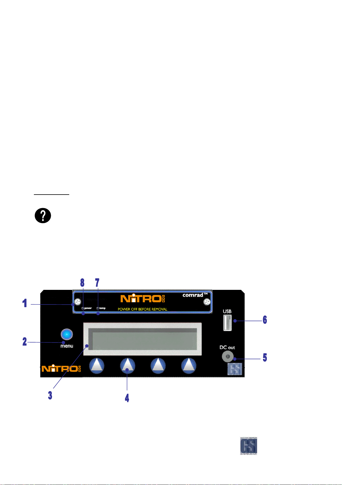
Figure 1111: Front Panel
Figure Figure
: Front Panel....
: Front Panel: Front Panel
-9-
1111
comrad
comrad™™™™ ---- Removable hard drive. DO NOT PULL
comradcomrad
2222
Main Menu button
Main Menu button ---- Press to save settings, move up a menu level and move within menu
Main Menu button Main Menu button
3333
Smart LCD Display
Smart LCD Display ---- Backlit for easy viewing
Smart LCD Display Smart LCD Display
4
4
Menu Control Buttons
Menu Control Buttons ---- Easy navigation through menu
4 4
Menu Control Buttons Menu Control Buttons
5
5
5555VDC Out
5 5
6666
7777
8888
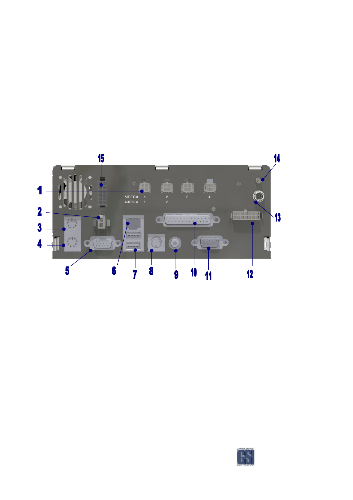
Rear Panel
Rear Panel....
Rear PanelRear Panel
VDC Out ---- Used to power up external NiTRO comrad™ with DC to DC Cable
VDC Out VDC Out
USB A
USB A ---- Connect external comrad™ to USB port to download video files or connect USB to Ethernet adaptor and
USB A USB A
crossover cable to connect PC or laptop
comrad
comrad Temp LED
comradcomrad
comrad
comrad Power LED
comradcomrad
Temp LED ---- comrad™ temperature indicator
Temp LED Temp LED
Power LED ---- comrad™ power status
Power LED Power LED
DO NOT PULL comrad
DO NOT PULL DO NOT PULL
comrad™ OUT WHILE SYSTEM IS RUNNING.
comradcomrad
™ OUT WHILE SYSTEM IS RUNNING.
™ OUT WHILE SYSTEM IS RUNNING.™ OUT WHILE SYSTEM IS RUNNING.
Figure
Figure 2222:
Figure Figure
1111 Video
2222 2222 Pin Molex Connector
3333 Mouse Input
4444
5555
6666
7777 USB A
8888 SSSS----Video Output
9999
10
10 Parallel Port
1010
11
11 DB
1111
12
12
1212
13
13 Audi
1313
14
14
1414
15
15 Remote Panel (Build Option)
1515
*
: Rear Panel
Rear Panel....
: :
Rear PanelRear Panel
Video/Audio
/Audio IN
VideoVideo
Pin Molex Connector ---- Power input
Pin Molex Connector Pin Molex Connector
Mouse Input ---- Not Used
Mouse Input Mouse Input
Keyboard
Keyboard ---- Connect keyboard to navigate through menus instead of menu control buttons
Keyboard Keyboard
CRT (SVGA)
CRT (SVGA) ---- Connect computer monitor to view the menu display (alternate output)*
CRT (SVGA) CRT (SVGA)
Ethernet
Ethernet Port
Ethernet Ethernet
USB A ---- Connect external comrad™ to USB port to download video files or connect USB to Ethernet adaptor and
USB A USB A
crossover cable to connect PC or laptop
Video Output ---- Connect TV to view the menu display (alternate output)*
Video Output Video Output
Video Output
Video Output ---- Connect TV to view the menu display (alternate output)*
Video Output Video Output
Parallel Port ---- Not used
Parallel PortParallel Port
DB----9 Port (RS
9 Port (RS----232)
DBDB
9 Port (RS9 Port (RS
Sensors
Sensors ---- Connect sensor harness
SensorsSensors
Audio
o OUT
AudiAudi
o o
GPS Antenna (Build Option)
GPS Antenna (Build Option) ---- A GPS Antenna can be connected so that speed and position can be recorded
GPS Antenna (Build Option)GPS Antenna (Build Option)
Remote Panel (Build Option) ---- Remote Panel used for configuration
Remote Panel (Build Option)Remote Panel (Build Option)
All three outputs will display the same image with the menu display, any of the three can be used.
IN ---- 4 Molex camera and audio inputs. Audio is not recorded from the last two
/Audio/Audio
IN IN
Port ---- Used to connect recorder to Local Area Network (LAN)
Port Port
232) ---- Not used
232) 232)
OUT ---- RCA audio output can be connected to speakers
OUTOUT
-10-

Figure
Figure 3333: Power Input
Figure Figure
: Power Input –––– Pin
: Power Input : Power Input
Figure
Figure 4444: Sensor Input
Figure Figure
: Sensor Input –––– Pin
: Sensor Input : Sensor Input
PIN
PIN DE
PINPIN
1 Extra 2, User Defined - - Brown Optional
2 Extra 1, User Defined - - Green Optional
3 Ignition Trigger - - Red Connect to Accessory +12V
4 Alarm Button - Black Use for Driver Alarm
5 Alarm LED - White - Optional
6 GND Black - - 7 NC - - - 8 Extra 3, User Defined - - Blue Optional
9 Warning Light Trigger - - White To Warning Light Circuit
10 Brake Light Trigger - - Orange To Brake Light Circuit
11 Stop Arm Trigger - - Yellow To Stop Arm Circuit
12 Record Light Indicator - Green - Optional
13****
14 Speed Sensor Green - - Optional
PIN
PIN DESCRIPTION
DESCRIPTION WIRE COLOR
PINPIN
DESCRIPTIONDESCRIPTION
2
GND
1
12V Main
Pin----outs
Pin Pin
8
8 9 10 11 12 13
9 10 11 12 13 14
8 8
9 10 11 12 13 9 10 11 12 13
1 2 3 4 5 6 7
1 2 3 4 5 6 7
1 2 3 4 5 6 71 2 3 4 5 6 7
Pin----outs
outs....
Pin Pin
outsouts
DESCRIPTION
SCRIPTION
DEDE
SCRIPTIONSCRIPTION
12VDC Output**** Red Red - -
XXXX ---- Speed Sensor Harness. YYYY ---- Alarm & LED Harness. ZZZZ ---- Sensor Harness
outs....
outsouts
WIRE COLOR
WIRE COLORWIRE COLOR
Black
Red
WIRE
WIRE
WIRE WIRE
COLOR
COLOR
COLORCOLOR
3
3 Lead
3 3
Lead
LeadLead
The NiTRO™ System power
14
14 14
COLOR
COLOR
COLORCOLOR
XXXX
4
4 Lead
4 4
negative cable should be
connected to a solid chassis grounding area.
WIRE
WIRE
WIRE WIRE
Lead
LeadLead
WIRE
WIRE
WIRE WIRE
COLOR
COLOR
COLORCOLOR
YYYY
7
7 Lead
Lead
7 7
LeadLead
ZZZZ
FUSE PANEL CONNECTION
FUSE PANEL CONNECTION
FUSE PANEL CONNECTIONFUSE PANEL CONNECTION
**** Never connect to ground.
-11-
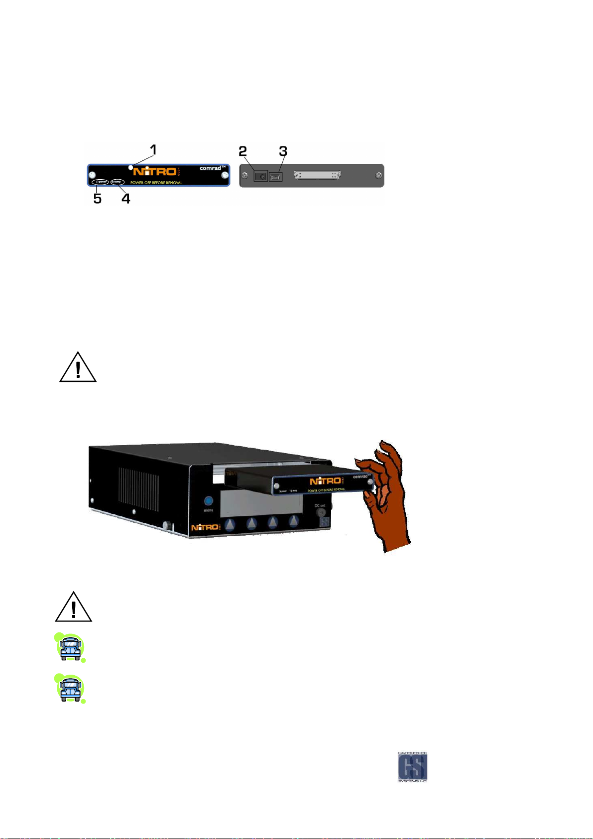
comrad
comrad™™™™....
comradcomrad
Front Panel Diagram Rear Panel Diagram
Figure
Figure 5555:::: comrad
Figure Figure
comrad™
comradcomrad
™ ---- Front and Rear Panels.
™ ™
Front and Rear Panels.
Front and Rear Panels. Front and Rear Panels.
1111 comrad
comrad™ ---- Removable hard drive
comradcomrad
2222 comrad
comrad™ Power
comradcomrad
3333 Mini USB
Mini USB ---- Used to connect comrad™ to PC or externally to NiTRO™ 900 as an external drive
Mini USBMini USB
4444 comrad
comrad™ Temp LED
comradcomrad
5555 comrad
comrad™ Power LED
comradcomrad
Power ---- Connect power source to comrad™
Power Power
Temp LED –––– Lit when the NiTRO™ system is out of temperature range
Temp LED Temp LED
Power LED –––– Lit when the NiTRO™ system is powered up.
Power LED Power LED
Shutdown the NiTRO™ System prior to removal of the comrad™. Do not remove the comrad™ when the
comrad™ Power LED is lit.
comrad
comrad™ Extraction
comradcomrad
™ Extraction....
™ Extraction™ Extraction
Figure
Figure 6666:
Figure Figure
: comrad
comrad™ Extraction
: :
comradcomrad
If the NiTRO™ System is running, turn system off and wait for the comrad™ LED to go out. Do not remove
comrad™ while the NiTRO System is running.
Pull firmly on the comrad™ to remove it.
To insert comrad™, ensure it is right side up and in line with the NiTRO™ 900 Control Unit. Firmly push on
front of the comrad™, ensure it is seated properly with a good connection at the back
™ Extraction....
™ Extraction™ Extraction
-12-
Inside
Glove Box
or
Behind Modesty Panel
Driver’s Console
Inside or on
Ensure the NiTRO™ system is off while inserting the comrad™
Installation
Installation....
InstallationInstallation
Always refer to your applicable Vehicle Safety Regulations before mounting any
hardware.
Ten Steps
Ten Steps for Installers
Ten StepsTen Steps
for Installers....
for Installers for Installers
Locate a site for the NiTRO™ System
Locate a site for the camera(s)
Locate a site for the GPS Antenna (optional)
Locate a site for the IR Illuminator (optional)
Locate site for all other accessories, ie. Alarm Button, Record LED (optional)
Mount the Isolation Suspension System plate
Run Power harness through enclosure to destination
Connect the constant power on the power harness to the Bus battery
Run the camera harness(es) to the camera destination(s)
Run the Sensor harness to the destination
Installers should refer to the individual product installation sheets that are included
for each part listed below:
Camera(s) Power Harness
GPS Camera Harness(es)
All Accessories
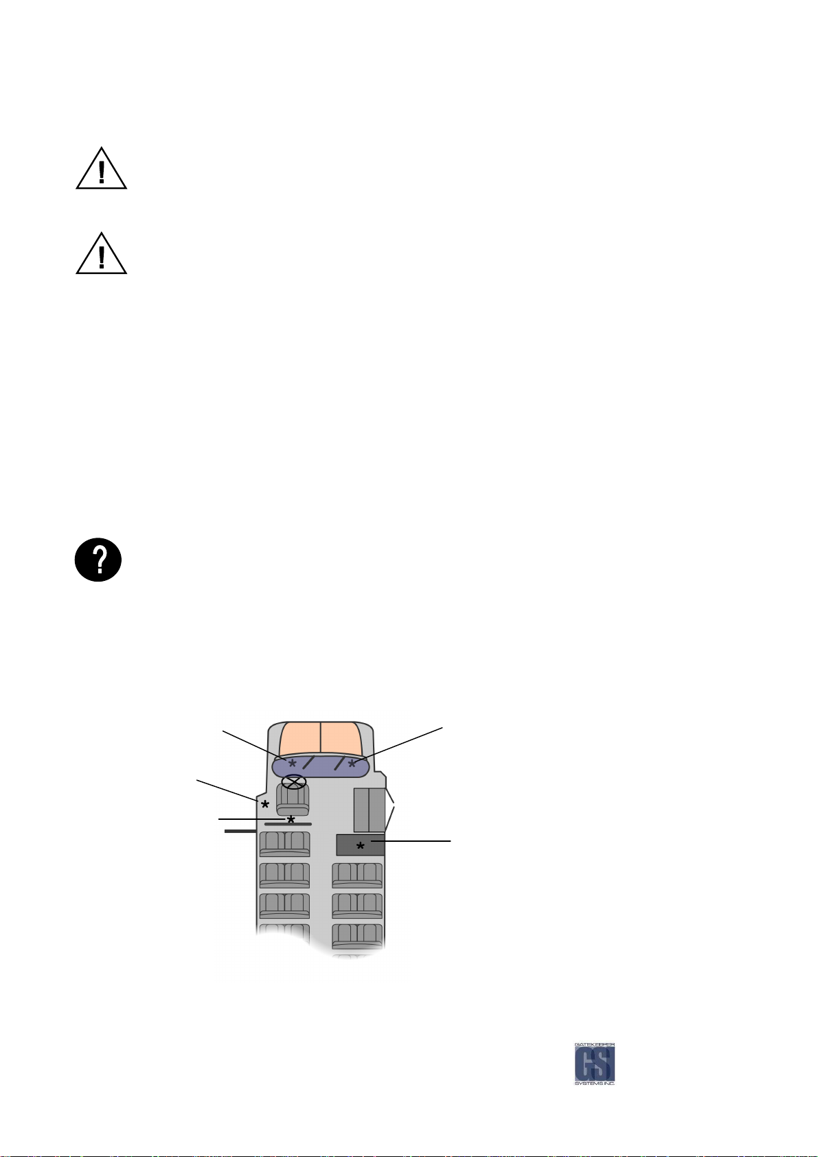
Recommended
Recommended System Locations
Recommended Recommended
Behind Driver’s Seat
Figure
Figure 7777: Recommended System
Figure Figure
: Recommended System LLLLocations
: Recommended System : Recommended System
System Locations....
System LocationsSystem Locations
Bulkhead
ocations....
ocationsocations
Under Dash Board
-13-
Mounting the System.
Mounting the System.
Mounting the System.Mounting the System.
Always use ‘star’ washers with fasteners, Use nuts and bolts whenever possible.
Check for:
Apply even torque to fasteners to avoid distorting the Mounting Plate.
Remember to leave enough space around the front of the NiTRO System so the door can be easily
installed, accessed, locked, and that the comrad™ can slide out freely.
When bolting the Mounting Plate through a sheet metal surface, use ‘fender’ washers on the back of
the sheet metal to help spread the torque load.
Route the power harness, camera harness(es), and accessory harness(es) through the Rear Door to
the installation destination(s).
Leave enough cable slack at the Rear End Cap,12 inches.
Safety
Not blocking passenger or driver access
Not obstructing driver’s view
Will not snag loose clothing or carry-on items
Accessibility
To the NiTRO 900 front panel for configuring & downloading
For easy comrad™ removal and insertion
For easy harness routing and connecting
Reliability
Away from dirt, heat, and moisture
Ensure sufficient airflow for enclosure fan and vents
Solid/flat mounting surface
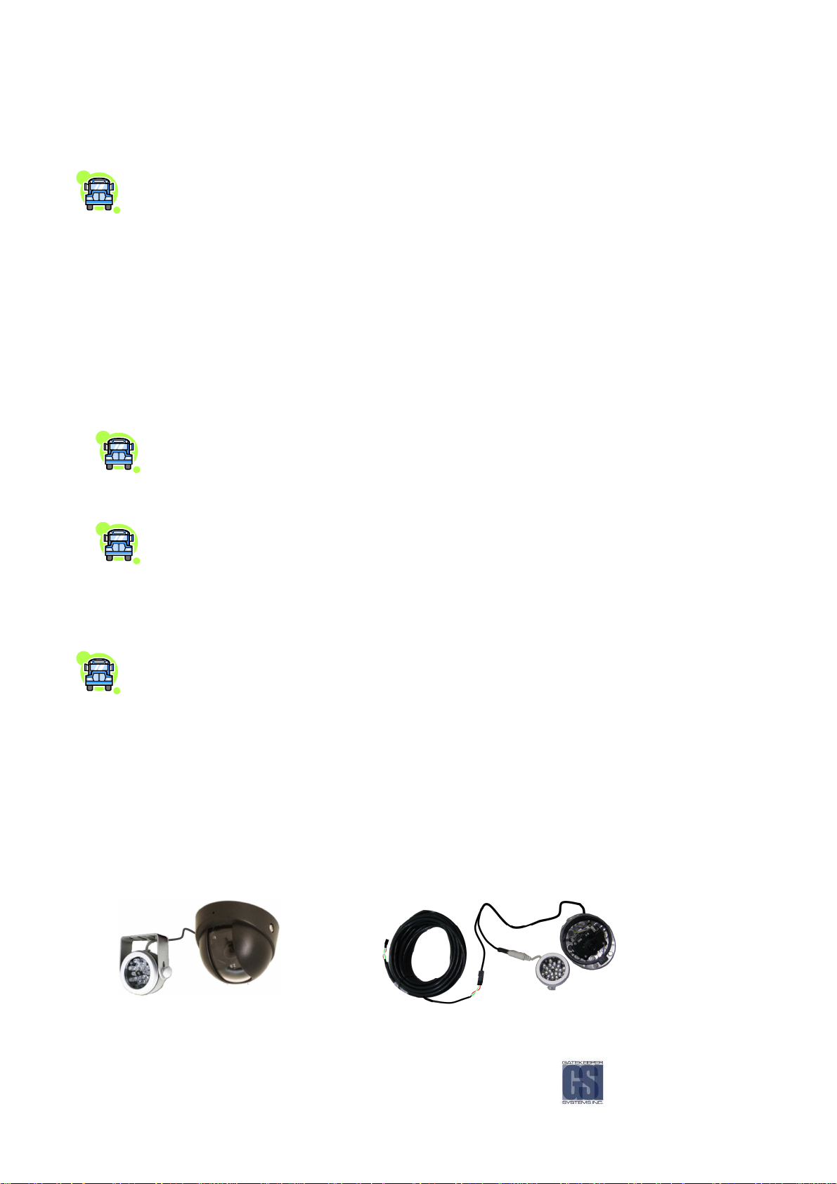
Recommended Location for the IR Illuminator
Recommended Location for the IR Illuminator....
Recommended Location for the IR IlluminatorRecommended Location for the IR Illuminator
Generally at the front of the Bus beside the front camera, as close to the center as possible.
Be sure to stagger the IR relevant to the front camera so as to allow easier access to the camera
dome screws and IR Illuminator screws.
Avoid areas where artificial light may cause “confusion” for the IR Illuminator which will affect the
proper function of the Illuminator.
Position the IR Illuminator so that there is an unobstructed view to the back of the bus. Illuminator
should be aimed towards the Emergency Exit sign at the back of the bus.
Bracket must be securely fastened to the ceiling or bulkhead.
Power connector should be inside bulkhead or pushed into ceiling cavity.
Illuminator should be aimed towards the Emergency Exit sign at the back of the bus.
Ensure minimal exposure of the harness.
Figure
Figure 8888:
Figure Figure
: IR20, Camera Location and Wiring.
IR20, Camera Location and Wiring.
: :
IR20, Camera Location and Wiring.IR20, Camera Location and Wiring.
-14-
Recommended Location for Alarm Button
Recommended Location for Alarm Button....
Recommended Location for Alarm ButtonRecommended Location for Alarm Button
Generally mounted in a location that is within reach of the driver where the drivers hand will naturally
fall into place.
Alarm Button
Alarm Button Connections.
Alarm Button Alarm Button
Recommended Location for Record LED
Recommended Location for Record LED....
Recommended Location for Record LEDRecommended Location for Record LED
Record LED connections
Record LED connections....
Record LED connectionsRecord LED connections
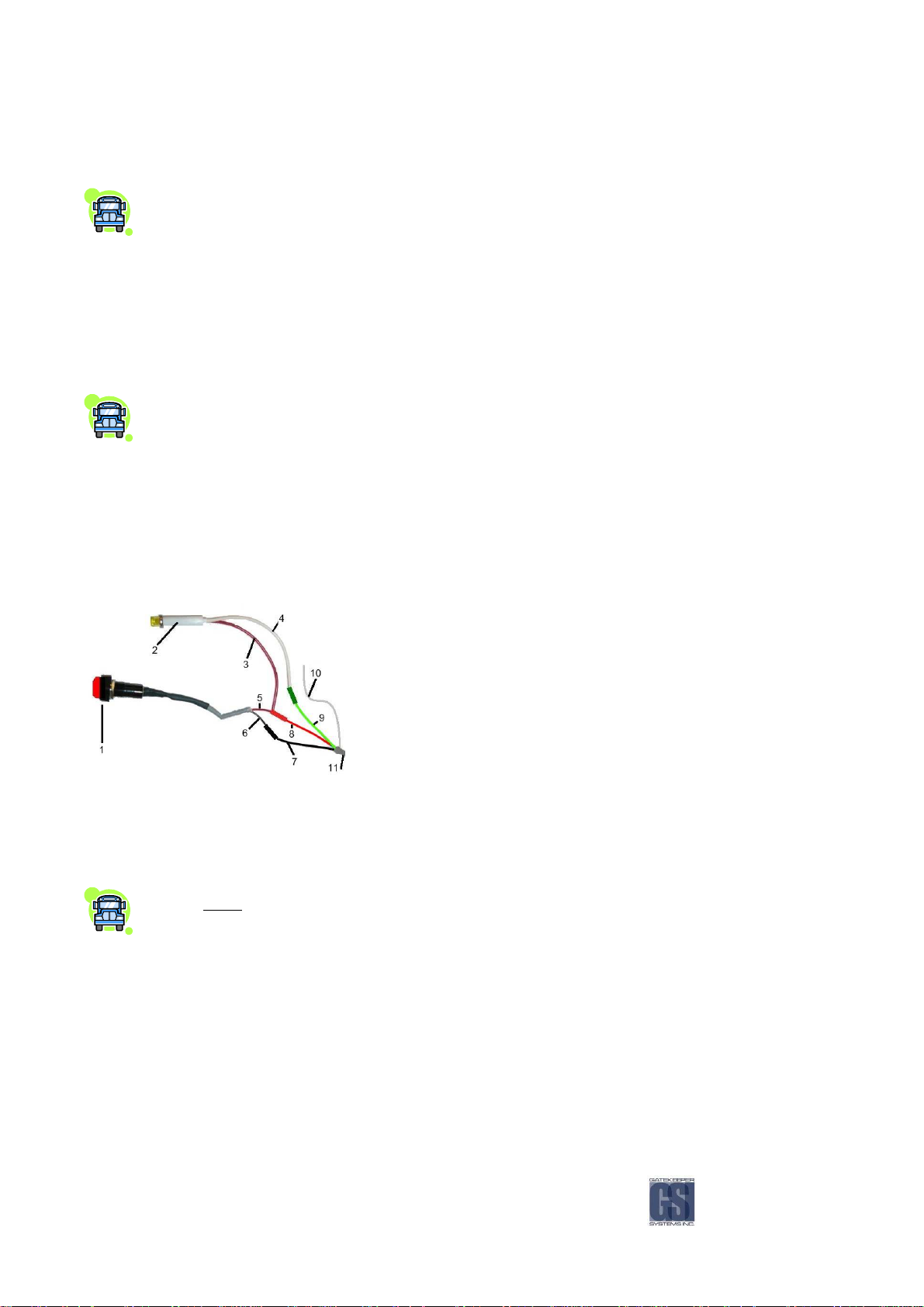
Figure
Figure 9999: Alarm Button/Record LED Splice.
Figure Figure
: Alarm Button/Record LED Splice.
: Alarm Button/Record LED Splice.: Alarm Button/Record LED Splice.
Recommended location is towards the front of the left switch panel.
Connections.
Connections.Connections.
Red lead(5) is connected to Red lead (12v) from Alarm Harness(8) with Red lead(3) from Record LED.
Black lead(6) is connected to Black lead(7) on the 4 conductor cable on the Sensor Harness(11).
Generally mounted out of the drivers line of sight as to avoid any distractions to the driver.
Recommended location is towards the rear of the left side switch panel.
Red lead(3) is connected to Red 12V lead in Alarm Harness(8) with Red lead(5) from Alarm Button.
White lead(4) is connected to Green lead(9) on the Four conductor cable on the Sensor Harness(11).
1. Alarm Button.
2. Record LED.
3. Record LED Red Lead.
4. Record LED White Lead.
5. Alarm Button Red Lead.
6. Alarm Button Black Lead.
7. Alarm & LED Harness Black Lead.
8. Alarm & LED Harness Red Lead.
9. Alarm & LED Harness Green Lead.
10. Alarm & LED Harness White Lead.
(Currently unused)
11. Alarm & LED Harness
Routing the Power Harness
Routing the Power Harness....
Routing the Power HarnessRouting the Power Harness
Constant Power connection MUST ALWAYS be made directly to battery.
NOTE:
NOTE: On rear engine buses, an alternative 12V source in the power distribution panel can be utilized.
NOTE:NOTE:
However, connection will vary from installation to installation.
Always use grommets when running the harness through sheet metal holes.
Avoid excessively tight bends especially around metal surfaces.
Use fuse holder and the 15 Amp fuse provided on the 12V+ connection (do not exceed 15 Amp fuse).
Connect fuse as close to power source as possible.
Use cable ties to secure harness and fuse holder.
Use correct terminal size for wire gauge.
10-12 AWG = Yellow
14-16 AWG = Blue
18-22 AWG = Red
Use ratcheting crimpers for terminal installation.
-15-

If grounding to a painted surface, scrape off paint and use ‘star’ washer between terminal and
metal surface.
DO NOT use painted or anodized fasteners.
Before connecting constant power, cut off excess slack.
Before connecting power directly at battery, verify that the system maintains a minimum of
10Volts during engine cranking. Testing requires starting the bus, with a multimeter connected to
battery. Confirm voltage does not drop below 10V during cranking. If voltage drops, advise
mechanic at bus garage that the batteries may need to be replaced.
Routing the Camera Harness(es)
Routing the Camera Harness(es)....
Routing the Camera Harness(es)Routing the Camera Harness(es)
Route the camera harness(es) and accessory harness(es)
Always use grommets when running the harness through sheet metal holes
Routing the Sensor Harness
Routing the Sensor Harness....
Routing the Sensor HarnessRouting the Sensor Harness
Avoid excessively tight bends especially around metal surfaces
Coil and tie off excess harness in a safe place
Route the Ignition wire (Red) to Accessory 12V+, directly to the steering column, fuse box, or to the
secondary side of the solenoid
Always use grommets when running the harness through sheet metal holes
Avoid excessively tight bends especially around metal surfaces
All unused sensor/indicator wires should be tied off and protected from touching ground.
Coil and tie off excess harness in a safe place
Refer to the Sensor Pin-out diagram on Page 11 Figure 2 for connection pin-outs.
-16-
Installing the Dome Camera
Installing the Dome Camera....
Installing the Dome CameraInstalling the Dome Camera
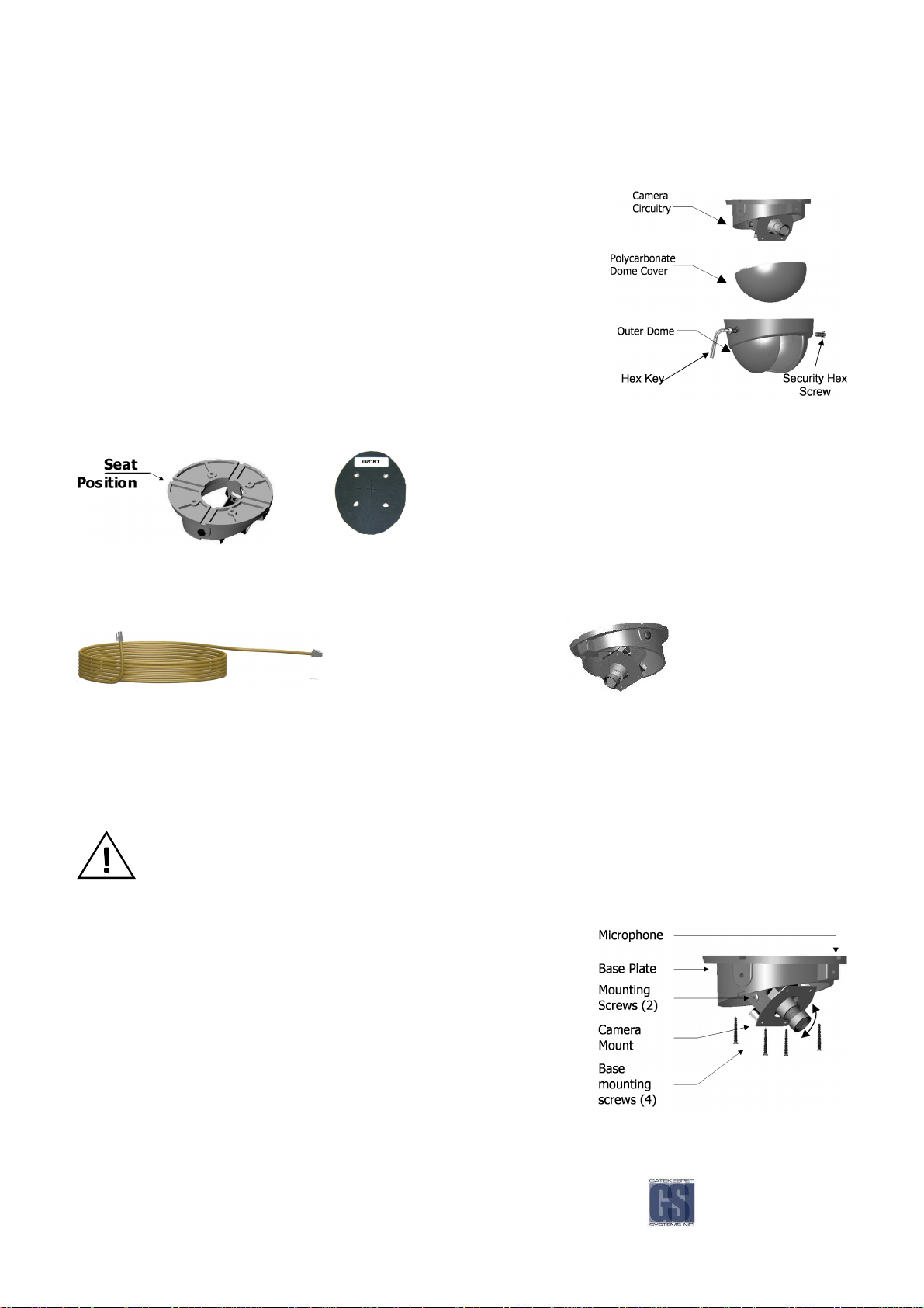
1. Disassemble the dome camera by removing the outer polycarbonate
dome. Loosen Phillips screws to allow camera board to move freely.
2. Ensure the included gasket is in place between dome baseplate and
mounting surface. This gasket is required as it acts as a cushion to
absorb vibration and aid in elimination of wind noise from the roof of the
bus. Determine seat position for camera harness and insert camera
harness into seat position.
Use the FRONT label as your guide. Ensure the Lens/Microphone
assembly is located directly above the FRONT label.
Camera Gasket
Figure
Figure 10
10: Removing Outer and Polycarbonate Dome.
Figure Figure
: Removing Outer and Polycarbonate Dome.
1010
: Removing Outer and Polycarbonate Dome.: Removing Outer and Polycarbonate Dome.
Figure
Figure 11
11: Camera Seat Position.
Figure Figure
: Camera Seat Position.
1111
: Camera Seat Position.: Camera Seat Position.
Attach the Molex connector from camera harness to the Molex connector attached to the camera circuitry.
3. If mounting to Bulkhead of the bus follow ‘Bulkhead Mount’ instructions on the following page.
4. Tuck attached camera harness behind the camera circuitry and then mount base with the four screws supplied
(Figure 12, Page 21).
5. Focus camera by referring to ‘Focusing Camera Lens’ on the following page.
6. After final check re-attach Polycarbonate dome cover and outer dome with hex screws.
Do not clean polycarbonate dome with any agents.
Bulkhead
Bulkhead Mount
BulkheadBulkhead
Return to step 4 of ‘Installing the Dome Camera’
Mount....
Mount Mount
Remove the two bracket mounting screws.
Rotate camera mount 180° (upside down) and reattach to base
plate.
Ceiling Mo
Ceiling Mount
Ceiling MoCeiling Mo
Bulkhead
Bulkhead Mount
BulkheadBulkhead
unt - Microphone should be situated facing back of bus
untunt
Mount - Microphone should be situated facing floor.
Mount Mount
Figure
Figure 12
12: Mounting the Camera
Figure Figure
-17-
: Mounting the Camera....
1212
: Mounting the Camera: Mounting the Camera
Focusing Camera Lens
Focusing Camera Lens....
Focusing Camera LensFocusing Camera Lens
Connect camera harness input to the back of the NiTRO™ 900 and power up NiTRO™ 900 system.
Remove the Polycarbonate Dome
cover and outer dome.
Connect the’ second video cable’
(CAMWHAVIDEOCABLE) to the pin connector on the
camera board and then to the video input on a
monitor a live video image will display on screen to
allow for easy lens adjustment.
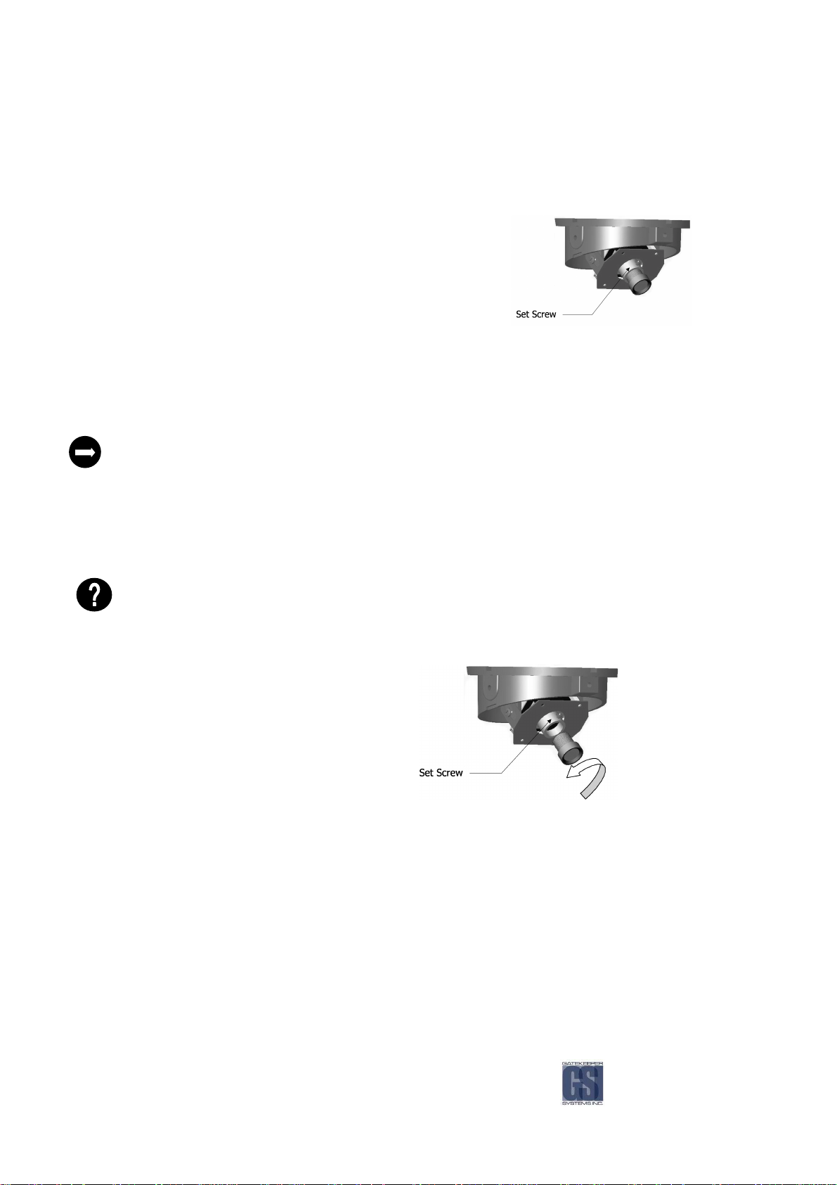
• Loosen the small set screw that is located on the base of the lens.
• Turn the lens slightly clockwise or counter clockwise until desired focus is reached.
• Tighten set screw to lock focus in place.
Adjusting the Field of View
Adjusting the Field of View....
Adjusting the Field of ViewAdjusting the Field of View
Adjust field of view by loosening the bracket mounting screws and rotating the camera mount bracket. Ensure limited
ceiling is seen in camera image.
Be sure to test the focus of the camera with the Polycarbonate Dome in front of the lens before making final
adjustment. Some cameras may be slightly out of focus when the Polycarbonate cover is put back on. Should
this occur, simply loosen the set screw on the lens, turn the lens 1/8 of a turn counter clockwise and tighten
screw.
It is best to attach a TV monitor to the NiTRO™ 900 to capture the desired field of view of the camera, at the
same time the lens focus can be checked (see Lens Setup under Configuration, Basic Menu).
Fig
Figure
ure 13
13:::: Focusing The Camera
FigFig
Focusing The Camera....
ure ure
1313
Focusing The Camera Focusing The Camera
Changing Camera Lens
Changing Camera Lens....
Changing Camera LensChanging Camera Lens
Remove Outer Dome Cover and Polycarbonate Dome by removing the two hex screws with the supplied Hex Key.
Remove lens by loosening set screw, then turning
lens counter clockwise, replace with new lens
(Figure 14).
Focus Camera as per ‘Focusing Camera Lens’
instruction page 22.
Figure
Figure 14
14:
Figure Figure
1414
: Camera Sea
Camera Seat Position.
: :
Camera SeaCamera Sea
t Position.
t Position.t Position.
-18-
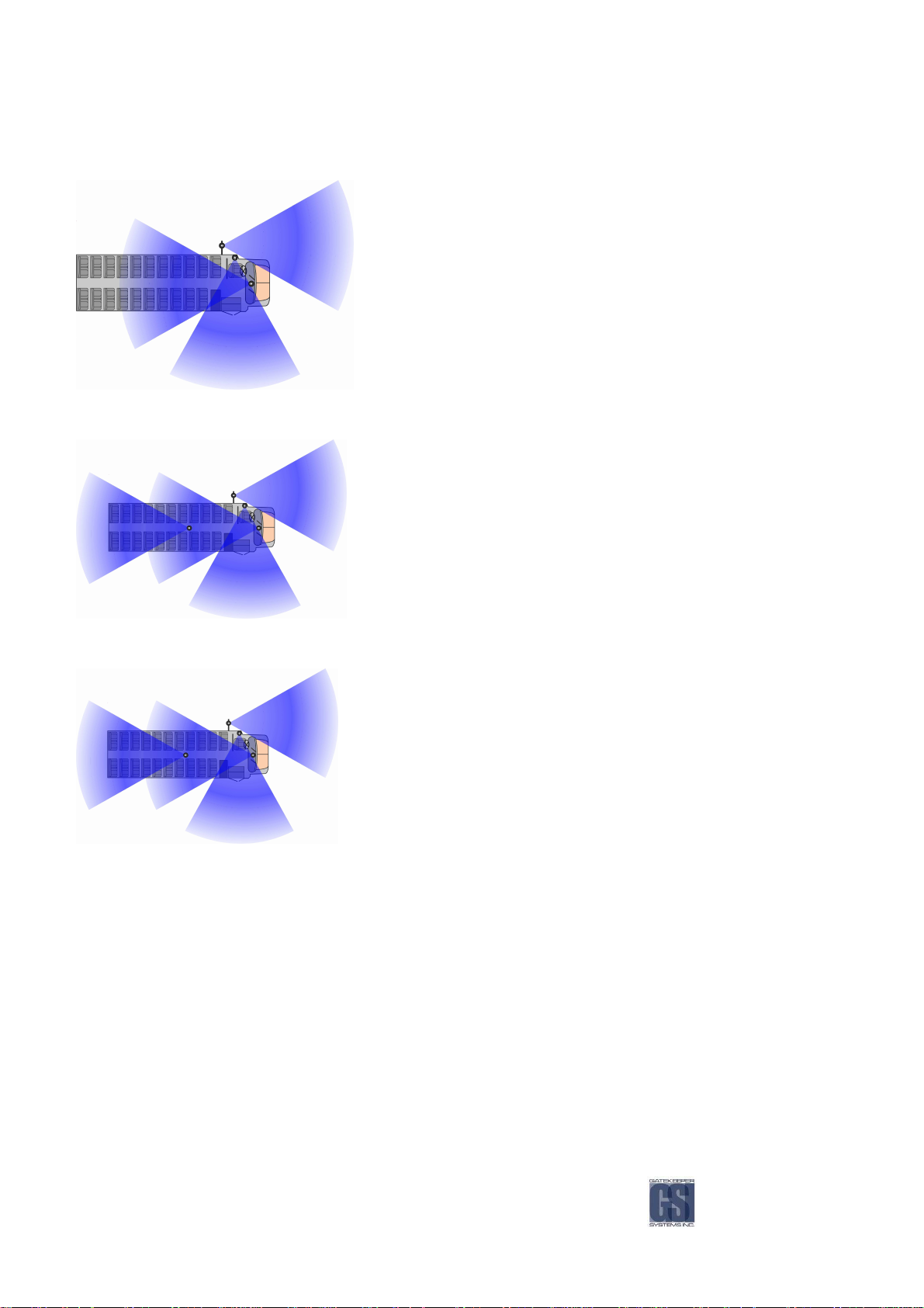
Recommended Camera Locations.
Figure
Figure 15
15:
: Three Camera Configuration
Figure Figure
Three Camera Configuration....
1515
: :
Three Camera ConfigurationThree Camera Configuration
Check For:
Check For:
Check For:Check For:
Wire Routing:
• Ceiling mount recommended.
• Do not obstruct walkways.
• Avoid contact with abrasive metal to prevent short circuits.
• Camera harness to be connected through opening in base.
• Use existing wire paths wherever possible (ie: radio, speakers,
etc).
• Avoid excessively tight bends especially around metal surfaces.
• Always use grommets when routing through sheet metal holes.
• Coil and tie off excess harness or tuck up into ceiling.
Figure
Figure 16
16:
Figure Figure
1616
Figure
Figure 17
17:
Figure Figure
1717
: Four Camera Configuration
Four Camera Configuration....
: :
Four Camera ConfigurationFour Camera Configuration
: Alternate Four Camera Configuration
Alternate Four Camera Configuration....
: :
Alternate Four Camera ConfigurationAlternate Four Camera Configuration
-19-

Quick Configuration Settings for Installers
Quick Configuration Settings for Installers....
Quick Configuration Settings for InstallersQuick Configuration Settings for Installers
The Configuration menu allows the user the ability to fully customize each system. To access the configuration menu, press
and release the Blue menu button to the left of the LCD screen. Press and release this button until the Configuration option
appears on the LCD and then press GO using the button below it on the LCD screen. After you have changed a value under
a particular menu, you will see a message stating “Saving Config”, this message wil appear for five seconds. Once
completed you will see a second message stating “Config Saved” this will also appear for five seconds. Use the on-screen
Right and Left arrows to choose Basic, Advanced or System and then press GO.
The Configuration menu is separated into three sub menus: Basic, Advanced and System. Use the menu control buttons
to navigate to BASIC and press GO.
Lens Setup
Lens Setup
Lens SetupLens Setup
Set ID
Set ID
Set IDSet ID
Set Timezone
Set Timezone
Set TimezoneSet Timezone
Set Date
Set Date
Set DateSet Date
Record Extend
Record Extend
Record ExtendRecord Extend
Audio
Audio If dual audio is required change this setting to Stereo.
Audio Audio
Reset
Reset Once Quick Configuration is complete, choose the Reset Option and then select VIDEO ONLY. This
ResetReset
All other settings are set by default; refer to the following pages for details if you wish to configure more settings
If all camera(s) connected to
If all camera(s) connected to the
If all camera(s) connected toIf all camera(s) connected to
Camera Type
Camera Type Set to Black & White
Camera TypeCamera Type
If more than one camera is connected to the
If more than one camera is connected to the NiTRO
If more than one camera is connected to the If more than one camera is connected to the
Cameras
Cameras Select the number of cameras (1 - 4) connected to the NiTRO™ 900
CamerasCameras
Can use to aim and focus camera(s)
Set as “Bus Number”, e.g. Bus 123
Scroll to correct time-zone for geographic area
Check to make sure date and time are correct
Determines the number of minutes the system will record after the ignition
has been switched off
will ensure that the customer will receive the system without any previous video on their comrad
the NiTRO
NiTRO 900
the the
NiTRONiTRO
900 are black & white:
are black & white:
900 900
are black & white: are black & white:
NiTRO 900
NiTRONiTRO
900::::
900 900
If you want to record from each camera with even time dwell
If you want to record from each camera with even time dwell::::
If you want to record from each camera with even time dwellIf you want to record from each camera with even time dwell
Camera Dwell
Camera Dwell Set to appropriate dwell time, ie. 10 seconds per camera
Camera DwellCamera Dwell
If you want to record from one camera and switch to another only when a sensor is activated
If you want to record from one camera and switch to another only when a sensor is activated, (ie. Switch to stop
If you want to record from one camera and switch to another only when a sensor is activatedIf you want to record from one camera and switch to another only when a sensor is activated
arm camera when stop arm is active):
Camera Dwell
Camera Dwell Set to Sensors
Camera DwellCamera Dwell
Sensor Setup
Sensor Setup Configure the appropriate sensor to switch to the correct camera when active
Sensor SetupSensor Setup
-20-

LENS SETUP
LENS SETUP
SET ID
LOAD ID
SET TIMEZONE
SET DATE
RECORD EXTEND
RECORD DELAY
Dwell Time: All cameras will switch, in order, in a specified time interval (the dwell time). The Time interval is 5-70
seconds in 5 second increments.
Setting the Configuration
Setting the Configuration....
Setting the ConfigurationSetting the Configuration
The Configuration menu allows the user the ability to fully customize each system. To access the configuration menu, press
and release the Blue menu button to the left of the LCD screen. Press and release this button until the Configuration option
appears on the LCD and then press GO using the button below it on the LCD screen. After you have changed a value under
a particular menu, you will see a message stating “Saving Config”, this message wil appear for five seconds. Once
completed you will see a second message stating “Config Saved” this will also appear for five seconds. Use the on-screen
Right and Left arrows to choose Basic, Advanced or System and then press GO.
For a walkthrough tutorial on how to use the integral LCD menu system, please see Appendix page 77.
The Configuration menu is separated into three sub menus: Basic, Advanced, and System. Use the menu control buttons
to navigate to BASIC and press GO.
Basic Configuration
Basic Configuration....
Basic ConfigurationBasic Configuration
There are seven menus under the BASIC sub menu. The menus are defined below. Refer to the following pages for a
detailed description of how to use each menu.
This menu is a tool for adjusting the camera, focusing the lens or troubleshooting tool.
The Set ID menu is used to input each Bus ID (up to 20 characters
configurations which will help with the video management of various vehicles.
20 characters).
20 characters20 characters
. This allows for different
. .
The Load ID menu allows you to load different configuration files into the recorder by selecting different
IDs that were previously saved.
The Set Timezone menu is used to set the recorder to the desired timezone. This will automatically
account for day light saving time adjustment.
The Set Date menu allows you to set the current time and date.
Allows you to adjust the amount of time the recorder will stay powered up and recording after the
vehicle’s ignition has been turned off.
The Record Delay setting allows you to adjust the amount of time the recorder will wait to record after
ignition has been turned on and the recorder has started up.
PURPOSE:
PURPOSE: In order to view the Lens Setup screen, you must have a TV or Monitor connected to either the S-video, RCA
PURPOSE:PURPOSE:
video or SVGA output port.
-21-

SET ID
LOAD ID
ENTRY
ENTRY: Press ‘Go’ to enter Lens Setup menu,
ENTRYENTRY
the screen now displays “Preview” and the
current time and date toggle back and forth.
Live video will appear on the TV/Monitor.
MESSAGES
MESSAGES: If the “No signal” menu appears
MESSAGESMESSAGES
instead of the date/time, or a blue screen is
shown, this indicates that either there is no
camera connected, no signal coming from the
camera, or that there is a problem with the
video input on the video card.
PURPOSE:
PURPOSE: Set ID allows for a unique identifier for each video or each video project. Each setting in the configuration menu
PURPOSE:PURPOSE:
will be saved under the ID. This unique name will be displayed in the subtitles, in the video file list and in the video file name.
All video saved to the hard drive is saved by this ID name.
ENTRY
ENTRY: Press ‘Go’ to enter the Set ID menu, the
ENTRYENTRY
current ID is displayed. The blinking number or
letter indicates which letter or number is active
to be changed. Use the left and right arrow
keys to move through the row and use the plus
and minus keys to scroll up or down through the
alphanumeric list. The ID can be set using
UPPERCASE, lowercase alphabet letters,
numbers 0 through 9, space and dash, with a
maximum of 20 characters.
OTHER
OTHER: The default ID will only be displayed if the
OTHEROTHER
ID has never been set, if a Reset Config or Reset
ALL has been performed or if the ID has never
been changed from default. DEFAULT CONDITION
PURPOSE:
PURPOSE: The Load ID menu allows you to select any ID that you have previously saved on the hard drive. Each time you
PURPOSE:PURPOSE:
make an ID, it is saved to the Config folder on the comrad™. Using the Load ID function allows you to select between any
ID you have saved by using the plus and minus keys to scroll through the list.
ENTRY
ENTRY: Press ‘Go’ to enter the Load ID menu,
ENTRYENTRY
the current ID will be flashing onscreen. Use
the plus or minus signs to scroll to another ID.
Pressing the blue menu button will load the new
ID you have selected.
OTHER
OTHER: Remember that only one ID can be
OTHEROTHER
saved in the Control unit at one time, but all ID’s
are saved on the comrad™. Therefore, if you
change comrad™’s, the last ID loaded or
activated will still be active when you install a
completely different drive. You will also be able
to load in any one of the ID’s from the new
comrad™.
DEFAULT CONDITION
EXIT
EXIT: Press the blue menu button to exit and return to Lens Setup, the
EXITEXIT
video picture will no longer appear on the splash screen.
DEFAULT CONDITION
DEFAULT CONDITION: N/A
DEFAULT CONDITIONDEFAULT CONDITION
EXIT
EXIT: Press the blue menu button to exit Set ID.
EXITEXIT
DEFAULT CONDITION: Factory Serial Number
DEFAULT CONDITIONDEFAULT CONDITION
EXIT
EXIT: Press the blue menu button to exit Load ID.
EXITEXIT
DEFAULT CONDITION: Current ID
DEFAULT CONDITIONDEFAULT CONDITION
-22-

SET TIMEZONE
SET DATE
RECORD DELAY
RECORD EXTEND
PU
PURPOSE:
RPOSE: Set Time zone by geographical area
PUPU
RPOSE:RPOSE:
ENTRY
ENTRY: Press ‘Go’ to enter the Time Zone menu. The
ENTRYENTRY
current time zone will be displayed. Most world time
zones are included in the list. Use the plus and minus
menu buttons to scroll through the list and select
desired time zone.
OTHER
OTHER: When a new time zone is selected compared to
OTHEROTHER
the current one, the time on the recorder will change to
reflect the new time zone.
Example: Current time zone is
EXIT
EXIT: Press the blue menu button to exit the Set Time zone menu.
EXITEXIT
US/Pacific and current time is 11:00am. Set new time
zone of US/Eastern and the time will automatically
change to 2:00pm or 14:00.
accurate, the time and date can be set using the Set
Date menu. Make sure to set to the correct time zone
first before setting the date and time.
PURPOSE:
PURPOSE: The Set Date menu allows you to set the current time and date for your region.
PURPOSE: PURPOSE:
ENTRY
ENTRY: Press ‘Go’ to enter the Set Date menu. Use the
ENTRYENTRY
left and right arrow keys to scroll to each field and the plus
and minus signs to increment or decrement each number
in the field.
OTHER
OTHER: The video file name includes the date and time of
OTHEROTHER
the beginning of the file. The recorder files video on a firstin, first-out (FIFO) basis, therefore the oldest video will be
the first one overwritten when the disk becomes full.
PURPOSE:
PURPOSE: The Record Extend setting allows you to adjust the amount of time the recorder will record after the vehicle’s
PURPOSE:PURPOSE:
ignition has been turned off.
ENTRY
ENTRY: The record extend is set in minutes.
ENTRYENTRY
Choose from 1, 5-70 (in increments of 5) or No
Extend. Use the plus and minus signs to
increment the extend time.
DEFAULT CONDITION
PURPOSE:
PURPOSE: The Record Delay setting allows you to adjust the amount of time the recorder will wait to record after the
PURPOSE:PURPOSE:
ignition has been turned on.
ENTRY
ENTRY: The record delay is set in minutes.
ENTRYENTRY
Choose from No Delay, 1 or 5-70 (in
increments of 5). Use the plus and minus signs
to increment the delay time.
DEFAULT CONDITION
If the new time is not
EXIT
EXIT: Use the right arrow to advance to the next menu or left arrow to
EXITEXIT
advance to previous menu.
EXIT
EXIT: Use the right arrow to advance to the next menu or left arrow to
EXITEXIT
advance to previous menu.
DEFAULT CONDITION
DEFAULT CONDITION: Canada/Pacific
DEFAULT CONDITIONDEFAULT CONDITION
EXIT
EXIT: Press the blue menu button to exit the Set Date menu.
EXITEXIT
DEFAULT CONDITION
DEFAULT CONDITION: Last known time
DEFAULT CONDITIONDEFAULT CONDITION
DEFAULT CONDITION: 10 Minutes
DEFAULT CONDITIONDEFAULT CONDITION
DEFAULT CONDITION: No Delay
DEFAULT CONDITIONDEFAULT CONDITION
-23-

STARTUP MODE
SET UNITS
CALIBRATE TEST
SET PULSES
AUDIO
SUBTITLE POSITION
CAMERA TYPE
CAMERAS
VIDEO STANDARD
CAMERA DWELL
RECORD QUALITY
RECORD FPS
SENSOR SETUP
SENSOR READINGS
VOLUME IN
VOLUME OUT
Use the menu control buttons to navigate to ADVANCED and press GO.
Advanced Configuration
Advanced Configuration....
Advanced ConfigurationAdvanced Configuration
There are sixteen menus under the ADVANCED sub menu. The menus are defined below. Refer to the following pages for
a detailed description of how to use each menu.
The Startup Mode allows the user to configure the system to startup in either Record mode,
Playback mode or Standby mode.
There are two options for the speed units to be used. The two choices are US (mph)
US (mph) or Metric (kph)
US (mph)US (mph)
Metric (kph).
Metric (kph)Metric (kph)
If the recorder is wired to monitor the speed of the vehicle, the pulses per unit need to be calibrated
to the speedometer. When the units are calibrated, the speedometer reading will appear on the
LCD screen and in the subtitles.
The Set Pulses menu is used to manually input how many pulses are in one distance unit. This is
used if the configuration was reset. As long as the value of pulses is known, the recorder can be recalibrated without having to redo the entire calibration test. This setting does not apply to GPS
Speed.
Stereo Audio can be recorded or ignored.
This setting determines the microphone audio level input.
This setting determines the audio level output.
The Subtitle Position allows you to position the subtitle text on the top or bottom of the video.
Camera Type allows for more record time if all the cameras used are black & white cameras.
If multiple cameras are connected to the system, the system must be configured for the correct
amount of active cameras: 1, 2, 3
1, 2, 3 or 4
1, 2, 3 1, 2, 3
4.
4 4
Video Standard select the appropriate video signal standard to match with the camera signal type,
NTSC or PAL
Camera Dwell is used to set the system up to automatically switch cameras when there is more than
one connected to the system.
The Record Quality allows you to record in Standard or High Resolution.
Frames per second relates to the video standard used:
-24-
In NTSC mode, the FPS is listed as 1, 5, 10, 15, 20, 25, 30
In PAL mode, the FPS is listed as 1, 5, 10, 15, 20, 25
The Sensor Setup menu allows you to configure each sensor name up to 5 characters and select
which camera is associated with each sensor
The Sensor readings menu displays and chooses all sensors that can be displayed in the subtitles.

STARTUP MODE
CALIBRATE TEST
SET UNITS
PURPOSE:
PURPOSE: The startup mode defines the state the recorder will be in when it has been turned on.
PURPOSE:PURPOSE:
ENTRY
ENTRY: Use the plus and minus signs to scroll
ENTRYENTRY
through the three options.
OTHER
OTHER:
OTHEROTHER
Record:
start recording – if record delay is set
to a value other than no delay then it
will wait the delay time before starting
to record.
Playback:
automatically display the playback
menu and a video playback window on
the video monitor.
Standby:
configuration screen, awaiting some
type of action upon startup.
PURPOSE
PURPOSE: The set units menu relates to units of measured speed. There are two options for the units to be used. The two
PURPOSEPURPOSE
choices are US
If metric is chosen, then the units are kph (kilometers per hour).
ENTRY
ENTRY: Use the plus and minus signs to toggle
ENTRYENTRY
between the two options.
DEFAULT CONDITION
PURPOSE
PURPOSE: If the recorder is wired to monitor the speed of the vehicle, the units need to be calibrated to the speedometer.
PURPOSEPURPOSE
When the units are calibrated, the speedometer reading will appear on the LCD screen and in the subtitles. If no
speedometer is hooked up, then speed will not be displayed on the screen.
speedometer is hooked up, then speed will not be displayed on the screen. Calibration does not need to be done if you are
speedometer is hooked up, then speed will not be displayed on the screen.speedometer is hooked up, then speed will not be displayed on the screen.
using GPS for speed readings.
ENTRY
ENTRY: Press ‘Go’ to enter the calibrate menu.
ENTRYENTRY
Press start to begin calibration and
start driving one measured mile or km.
Press Done after traversing one mile
(or km) or Cancel to stop in the middle
of calibration and return to the
Calibrate menu.
Calibration is complete when Done is
pressed; the pulses per unit are shown.
OTHER
OTHER: Whatever units were chosen in the Set
OTHEROTHER
Units menu will be displayed under the
calibration. After calibration is complete, the
number of pulses is automatically displayed in
the Set Pulses menu.
the recorder will automatically
the recorder will
the recorder will stay on the
US or Metric
Metric. If US units are chosen, the mph (miles per hour) will be displayed for the measurement of speed.
USUS
MetricMetric
Example: To calibrate the
EXIT
EXIT: Use the right arrow to advance to the next menu or left arrow to
EXITEXIT
advance to the previous menu. Press the blue menu button to exit and
return to the Advanced sub menu.
DEFAULT CONDITION
DEFAULT CONDITION: Record
DEFAULT CONDITIONDEFAULT CONDITION
EXIT
EXIT: Use the right arrow to advance to the next menu or left arrow to
EXITEXIT
advance to the previous menu. Press the blue menu button to exit and
return to the Advanced sub menu.
DEFAULT CONDITION: US
DEFAULT CONDITIONDEFAULT CONDITION
. If no
. If no . If no
EXIT
EXIT: Press the blue menu button to exit and return to the Calibrate
EXITEXIT
Test menu.
recorder for a vehicle traveling in miles per
hour:Press “Start” in the Calibrate Test menu on
DEFAULT CONDITION
DEFAULT CONDITION: N/A
DEFAULT CONDITIONDEFAULT CONDITION
-25-

SET PULSES
AUDIO
VOLUME IN
the recorder, and begin driving on measured
mile; when the mile is complete, press “Done”.
The menu will show how many pulses were in
that one mile and that value will be used to
calculate the vehicle’s velocity when recording.
PURPOSE
PURPOSE: The Set Pulses menu is used to manually input how many pulses are in one distance unit. This is used if the
PURPOSEPURPOSE
configuration was reset. As long as the value of pulses is known, the recorder can be re-calibrated without having to redo
the entire calibration test.
ENTR
ENTRYYYY: Press ‘Go’ to enter the set pulses menu.
ENTRENTR
Use the plus or minus sign keys to increment or
decrement each digit. Use the left and right
arrow keys to skip to the next digit.
OTHER
OTHER: If the Calibration test was completed,
OTHEROTHER
the pulses value will already be set in the Set
Pulses menu. DEFAULT CONDITION
PURPOSE
PURPOSE: Audio can be recorded as stereo input or ignored
PURPOSEPURPOSE
ENTRY
ENTRY: Use the plus and minus keys to toggle
ENTRYENTRY
between the options.
OTHER
OTHER:
OTHEROTHER
None:
the recorder will record video
without any audio.
Mono PCM Line:
record mono audio from Camera 1
with the video
Mono MP3 Line:
the audio takes up less space.
Stereo PCM Line:
record stereo audio from Cameras 1
and 2 with the video.
Stereo MP3 Line:
but the audio takes up less space. DEFAULT CONDITION
NOTE:
NOTE: When playing a video file from within MAXVIEW™ audio playback will be heard irrespective of which camera is
NOTE:NOTE:
chosen. If a saved video clip is played audio will only be available from either camera 1 or 2.
PURPOSE:
PURPOSE: This setting determines the microphone audio level input as captured during the recording. 0 being the lowest
PURPOSE:PURPOSE:
level; 100 being the highest level. When set to 0 the recording will have no audio.
the recorder will
the same as PCM but
the recorder will
the same as PCM
EXIT
EXIT: Press the blue menu button to exit and return to the Set Pulses
EXITEXIT
menu.
DEFAULT CONDITION: 00000000
DEFAULT CONDITIONDEFAULT CONDITION
EXIT
EXIT: Use the right arrow to advance to the next menu or left arrow to
EXITEXIT
advance to the previous menu. Press the blue menu button to exit and
return to the Advanced sub menu.
DEFAULT CONDITION: Mono MP3 Line
DEFAULT CONDITIONDEFAULT CONDITION
ENTRY:
ENTRY: Use the Plus and Minus signs to
ENTRY:ENTRY:
change the value to the required level.
DEFAULT:
-26-
EXIT:
EXIT: Use the right arrow to advance to the
EXIT:EXIT:
next menu or left arrow to advance to the
previous menu. Press the blue menu button to
exit and return to the Advanced sub menu.
DEFAULT: 75
DEFAULT:DEFAULT:

DEFAULT CONDITION
DEFAULT CONDITIONDEFAULT CONDITION
DEFAULT CONDITION
:
Color
DEFAULT CONDITION
DEFAULT CONDITIONDEFAULT CONDITION
DEFAULT CONDITION
: NTSC
VIDEO STANDARD
SUBTITLE POSITION
CAMERA TYPE
CAMERAS
VOLUME OUT
PURPOSE:
PURPOSE: This setting determines the audio level output. 0 being the lowest; 100 being the highest. When set to 0 during
PURPOSE:PURPOSE:
playback on the recorder this will act like audio out being muted. There will be no sound coming from the computer on
which the video is being reviewed.
ENTRY:
ENTRY: Use the Plus and Minus signs to
ENTRY:ENTRY:
change the value to the required level.
EXIT:
EXIT: Use the right arrow to advance to the
EXIT:EXIT:
next menu or left arrow to advance to the
previous menu. Press the blue menu button to
exit and return to the Advanced sub menu.
DEFAULT:
DEFAULT: 75
DEFAULT:DEFAULT:
PURPOSE
PURPOSE: Subtitle position allows the user to configure the subtitles to appear on the top of the video image or on the
PURPOSEPURPOSE
bottom of the video image when video is recorded.
ENTRY
ENTRY: Use the plus and minus keys to toggle
ENTRYENTRY
between top
top and bottom
toptop
bottom.
bottombottom
EXIT
EXIT: Use the right arrow to advance to the next menu or left arrow to
EXITEXIT
advance to the previous menu. Press the blue menu button to exit and
return to the Advanced sub menu.
DEFAULT CONDITION
DEFAULT CONDITION: Bottom
DEFAULT CONDITIONDEFAULT CONDITION
PURPOSE
PURPOSE: The purpose of this menu is to allow for more record time if the customer is using all Black & White cameras.
PURPOSEPURPOSE
ENTRY
ENTRY: Use the plus and minus keys to toggle
ENTRYENTRY
between CCCColor
olor or BBBBlack &
olorolor
lack & WWWWhite
lack & lack &
hite....
hitehite
EXIT
EXIT: Use the right arrow to advance to the next menu or left arrow to
EXITEXIT
advance to the previous menu. Press the blue menu button to exit and
return to the Advanced sub menu.
PURPOSE
PURPOSE: If multiple cameras are connected to the system, the system must
PURPOSEPURPOSE
active cameras 1, 2, 3
1, 2, 3 or 4
1, 2, 3 1, 2, 3
4.
4 4
must be configured for the correct amount of
mustmust
ENTRY
ENTRY: Use the plus and minus keys to toggle
ENTRYENTRY
between the options.
DEFAULT CONDITION
EXIT
EXIT: Use the right arrow to advance to the next menu or left arrow to
EXITEXIT
advance to the previous menu. Press the blue menu button to exit and
return to the Advanced sub menu.
DEFAULT CONDITION: 1
DEFAULT CONDITIONDEFAULT CONDITION
PURPOSE
PURPOSE: To select the appropriate video signal standard to match with the camera signal type.
PURPOSEPURPOSE
ENTRY
ENTRY: Use the plus and minus keys to toggle
ENTRYENTRY
between NTSC
NTSC and PAL
NTSCNTSC
PAL.
PALPAL
EXIT
EXIT: Use the right arrow to advance to the next menu or left arrow to
EXITEXIT
advance to the previous menu. Press the blue menu button to exit and
return to the Advanced sub menu.
-27-

RECORD FPS
CAMERA DWELL
SENSOR SETUP
RECORD QUALITY
PURPOSE
PURPOSE: Camera Dwell is used to set the system up to automatically switch cameras when there is more than one
PURPOSEPURPOSE
connected to the system. The options are to switch on SSSSensors
Sensors:
Sensors: Selected camera will switch when sensor becomes active
Sensors:Sensors:
Example: If camera 1 is set to main camera and camera 2 is set as the stop arm camera, the system will always record on
camera 1 until the stop arm sensor becomes active. As long as that sensor is active, it will record on camera 2 instead of
camera 1. When the stop arm sensor becomes inactive, the system will return to recording on camera 1.
Dwell Time
Dwell Time: All cameras will switch in order according to a specified time interval (dwell time). Time interval options are
Dwell TimeDwell Time
from 5555----70
ENTRY
ENTRY: Use the plus and minus keys to scroll
ENTRYENTRY
through all the options.
DEFAULT CONDITION
PURPOSE
PURPOSE: The Record Quality menu gives two options used for recording:
PURPOSEPURPOSE
ENTRY
ENTRY: Use the plus and minus keys to toggle
ENTRYENTRY
between the two options.
DEFAULT CONDITION
PURPOSE
PURPOSE: The Frames per second options relate to the video standard used.
PURPOSEPURPOSE
For NTSC mode, the FPS is listed as 1,
For PAL mode, the FPS is listed as 1, 5, 10, 15, 20, 25
ENTRY
ENTRY: Use the plus and minus keys to toggle
ENTRYENTRY
between the two options.
Note: The FPS cannot be changed if the Record
Quality is set to High Res
PURPOSE
PURPOSE: There are eight pins on the serial port that are used as sensors. Each sensor is displayed on the main recording
PURPOSEPURPOSE
screen when it becomes active. The character that gets displayed is the first character in the label. Example: IGN is active so
“I” is displayed. If the label was changed to “DOOR”, the letter “D” would be displayed.
ENTRY
ENTRY: Press ‘Go’ to enter the Sensor Setup menu.
ENTRYENTRY
Use the plus and minus sign keys to increment
each character. Use the left or right arrow keys to
jump to the next character and/or field.
70 seconds in 5 second increments.
7070
Standard:
Standard: 320 x 240 resolution at full 1 - 30 FPS
Standard:Standard:
High Res:
High Res: 640 x 480 resolution at only 5 FPS
High Res:High Res:
1, 5,
5, 10,
10, 11115,
10,10,
5, 20,
5,5,
1,1,
5,5,
1, 5, 10, 15, 20, 25
1, 5, 10, 15, 20, 251, 5, 10, 15, 20, 25
Lowering the FPS will increase the
record time
Label
Label:::: The default names are 3EX, ALM, IGN, DEFAULT CONDITION
LabelLabel
ensors only, or on a DDDDwell
ensorsensors
EXIT
EXIT: Use the right arrow to advance to the next menu or left arrow to
EXITEXIT
advance to the previous menu. Press the blue menu button to exit and
return to the Advanced sub menu.
EXIT
EXIT: Use the right arrow to advance to the next menu or left arrow to
EXITEXIT
advance to the previous menu. Press the blue menu button to exit and
return to the Advanced sub menu.
20, 25, 30
25, 30
20,20,
25, 3025, 30
EXIT
EXIT: Use the right arrow to advance to the next menu or left arrow to
EXITEXIT
advance to previous menu. Press the blue menu button to exit and
return to the Advanced sub menu.
EXIT
EXIT: Press the blue menu button to exit the Sensor Setup menu and
EXITEXIT
return to the Advanced sub menu.
DEFAULT CONDITION: Sensors with default labels, triggered on active
DEFAULT CONDITIONDEFAULT CONDITION
well TTTTime
ime interval.
well well
imeime
DEFAULT CONDITION: Sensors
DEFAULT CONDITIONDEFAULT CONDITION
DEFAULT CONDITION: Standard
DEFAULT CONDITIONDEFAULT CONDITION
DEFAULT CONDITION
DEFAULT CONDITION: 30
DEFAULT CONDITIONDEFAULT CONDITION
-28-

SENSOR READINGS
DISK USED
SERIAL
IP0
IP1
S
/W VERSION
DHCP REFRESH
STP, BRK, WRN, 1EX, 2EX. Each label can be
high (1)
changed (maximum 5 characters long).
Cam:
Cam: You can select which camera should
Cam:Cam:
become active when the associated sensor is
active.
Trg
Trg:::: The trigger defines either to trigger on an
TrgTrg
active high (1) or active low (0).
PURPOSE
PURPOSE: The Sensor readings menu displays all sensors that can be displayed in the subtitles. The default sensors are
PURPOSEPURPOSE
automatically displayed and cannot be turned off–they will always appear in the subtitles when they are active.
Sensor Readings can also be used to test whether sensors are working: 0 is displayed while the current sensor is inactive,
and 1 is displayed when the sensor is active.
T and V are the temperature and voltage of the system and can be turned on or off from being displayed in the subtitles.
The GPS is the GPS position of the vehicle, and speed_mph is the speed of the vehicle.
ENTRY
ENTRY: Press ‘Go’ to enter the Sensor Readings
ENTRYENTRY
menu. Use the left or right arrow keys to scroll to the
next sensor in the list. The T, V, and GPS sensors can
EXIT
EXIT: Press the blue menu button to exit the Sensor Readings
EXITEXIT
menu and return to the Advanced sub menu.
be turned off or on.
OTHER
OTHER: The speed units used will be correct
OTHEROTHER
according to the units configured in the Set Units
menu (ie. if the unit is set to Metric units, the speed
DEFAULT CONDITION
DEFAULT CONDITION: Sensors 1-8 – On, Temp, Voltage, GPS, etc.
will be recorded in kph, even though the sensor label
reads speed_mph).
DEFAULT CONDITIONDEFAULT CONDITION
– Off
Refer to the Sensor Pin-out diagram on page 11 Figure 2 for connection pin-outs.
Use the menu control buttons to navigate to SYSTEM and press GO.
System Configuration
System Configuration....
System ConfigurationSystem Configuration
There are eight menus under the SYSTEM sub menu. The menus are defined below. Refer to the following pages for a
detailed description of how to use each menu.
The disk used menu displays the percentage of storage spaced used up on the disk.
The unique serial number of the recorder is displayed. This serial number is also the default ID that is
displayed under Set ID.
When the recorder is connected to a LAN via the back Ethernet port, the IP address will be displayed.
When the recorder is connected to a laptop via the front USB port using the USB to Ethernet adaptor,
the IP address 192.168.1.1 will be displayed.
Utility used to poll the DHCP server.
The currently installed software version is displayed.
-29-

RESET
CLONE
DISK USED
SERIAL
IP0
IP1
Allows the user to reset current settings to defaults, erase all settings, or erase all video.
The system clone feature allows the user to recover a hard drive in case of disk corruption.
PURPOSE:
PURPOSE: The Disk Used menu displays the percentage of storage space used up on the disk.
PURPOSE:PURPOSE:
ENTRY
ENTRY: No entry, data already displayed on
ENTRYENTRY
screen.
EXIT
EXIT: Use the right arrow to advance to the next menu or left arrow to
EXITEXIT
advance to the previous menu. Press the blue button to return to the
System sub menu.
DEFAULT CONDITION
DEFAULT CONDITION: 1%
DEFAULT CONDITIONDEFAULT CONDITION
PURPOSE:
PURPOSE: The Serial menu displays the unique serial number of the recorder. This serial number is also the default ID that
PURPOSE:PURPOSE:
is displayed under Set ID.
ENTR
ENTRYYYY: No entry, data already displayed on
ENTRENTR
screen.
EXIT
EXIT: Use the right arrow to advance to the next menu or left arrow to
EXITEXIT
advance to the previous menu. Press the blue button to return to the
System sub menu.
DEFAULT CONDITION
DEFAULT CONDITION: The serial number
DEFAULT CONDITIONDEFAULT CONDITION
PURP
PURPOSE:
OSE: When the recorder is connected to a LAN or a Laptop via the rear Ethernet port, the IP address will be
PURPPURP
OSE:OSE:
displayed under IP0. This address is used to connect to the recorder over the network.
ENTRY
ENTRY: No entry, data already displayed on
ENTRYENTRY
screen. An IP address is only displayed if the
recorder is attached to a LAN or PC connection.
OTHER
OTHER: Refer to IP0 when trying to browse the
OTHEROTHER
recorder on a Local Area Network (LAN)
EXIT
EXIT: Use the right arrow to advance to the next menu or left arrow to
EXITEXIT
advance to the previous menu. Press the blue button to return to the
System sub menu.
DEFAULT CONDITION
DEFAULT CONDITION: Blank
DEFAULT CONDITIONDEFAULT CONDITION
A DHCP Server is required on the Local Area Network for the NiTRO™ unit to obtain an IP automatically through
the rear Ethernet port.
PURPOSE:
PURPOSE: When the recorder is connected to a laptop via the front USB port using the USB to Ethernet adaptor, the IP
PURPOSE:PURPOSE:
address 192.168.1.1 will be displayed under IP1. This address is used to connect to the recorder from that laptop.
ENTRY
ENTRY: No entry, data already displayed on
ENTRYENTRY
screen. An IP address is only displayed if the
recorder is attached to a USB to Ethernet
adaptor.
EXIT
EXIT: Use the right arrow to advance to the next menu or left arrow to
EXITEXIT
advance to the previous menu. Press the blue button to return to the
System sub menu.
-30-

S/W VERSION
RESET
DHCP REFRESH
OTHER
OTHER: When the recorder is connected to a
OTHEROTHER
LAN or a Laptop via the back Ethernet port, the
dynamic IP address will be displayed under IP0,
not IP1.
The NiTRO™ unit’s USB Ethernet connection acts as a DHCP Server. A DHCP Client on the Laptop/PC is required
for the Laptop/PC to obtain an IP automatically.
PURPOSE:
PURPOSE: Maintains communication with the DHCP server ensuring that an available IP address, if required, is obtained
PURPOSE:PURPOSE:
automatically. Refresh time is configurable from 5 minutes through to and including 30 minutes.
ENTRY:
ENTRY: Press ‘Go’ to enter DHCP Refresh
ENTRY: ENTRY:
menu. Use the plus and minus sign keys to
select the required refresh time.
DEFAULT CONDITION
PURPOSE:
PURPOSE: The S/W Version menu displays the currently installed software version. When the recorder gets a new update
PURPOSE:PURPOSE:
via Check for Updates or Upgrades copied from another comrad™ the new version of software can be confirmed here.
ENTRY
ENTRY: No entry, data already displayed on
ENTRYENTRY
screen.
PURPOSE:
PURPOSE: The Reset menu allows the user to reset current settings to defaults, erase all videos or erase all videos and
PURPOSE:PURPOSE:
reset settings to defaults.
ENTRY
ENTRY: Press ‘Go’ to enter the Reset menu.
ENTRYENTRY
OTHER
OTHER:
OTHEROTHER
Config: This will delete all configuration except
the default settings and reset the ID
back to the factory serial number
Video: This will completely erase all videos files
and clips on the recorder without any
option to retrieve them at a later date.
The configurations are not changed.
Cancel: This will cancel the reset and exit.
All: This will delete all the config files,
returning the unit to factory default.
You will be unable to retrieve any IDs
and all video will be deleted.
EXIT:
EXIT: Use the right arrow to advance to the next menu or left arrow to
EXIT: EXIT:
advance to the previous menu. Press the blue button to return to the
System sub menu.
EXIT
EXIT: Use the right arrow to advance to the next menu or left arrow to
EXITEXIT
advance to the previous menu. Press the blue button to return to the
System sub menu.
DEFAULT CONDITION
DEFAULT CONDITION: Installed S/W Version
DEFAULT CONDITIONDEFAULT CONDITION
EXIT
EXIT: Press Cancel or the blue menu button to exit the Reset menu and
EXITEXIT
return to the System sub menu.
DEFAUL
DEFAULT CONDITION
DEFAULDEFAUL
DEFAULT CONDITION: 5 minutes.
DEFAULT CONDITIONDEFAULT CONDITION
T CONDITION: Blank
T CONDITIONT CONDITION
-31-

CLONE
DC
DC DC
DC
––––
DC Cable
DC Cable DC Cable
DC Cable
USB Cable
USB CableUSB Cable
USB Cable
comrad™
comrad™comrad™
comrad™
PURPO
PURPOSE:
PURPOPURPO
on the cloned drive will be lost and a fresh system is copied onto it.
PROCEDURE:
PROCEDURE:
PROCEDURE:PROCEDURE:
ENTRY
ENTRY: Press ‘Go’ to enter Clone menu. Press
ENTRYENTRY
OK to begin cloning the hard drive.
OTHER:
OTHER: The Cloning feature is used to repair
OTHER:OTHER:
corrupt hard drives or to upgrade other units.
Remember, cloning will format the drive first, so
do not use clone if you want to keep the video
stored on the drive.
SE: Cloning a hard drive completely formats that drive and copies system files from the recorder. All files that were
SE:SE:
Connect the corrupt comrad™ to the front USB port of the recorder via a Dual Head USB 2.0 cable. Apply power
to the comrad™ either from the front DC Output with a DC to DC Cable or from the comrad™ power supply (12V,
3A).
When the drive is connected, one to three beeps will be heard to indicate the connection. The hard drive that will
be formatted is the one connected to the USB port.
The message “Clone HD to USB” will be shown. Press OK to begin the cloning process. The cloning process will
take several minutes and “Cloning…” will be displayed on the LCD while it is being cloned.
EXIT
EXIT: When the cloning process is complete the menu ends up on the
EXITEXIT
Clone HD to USB menu. Press cancel or the blue menu button to exit
the Clone menu.
When using the Dual Head USB Cable, ensure that the main head (the
one with two wires coming out of it) is plugged into the system.
Dual
Dual head
head
Dual Dual
Working
Working
Working Working
System
System
SystemSystem
Figure
Figure 18
18: Cloning a
Figure Figure
1818
head head
: Cloning a comrad
: Cloning a : Cloning a
The NiTRO™ System is incompatible with GSX System. Do not clone from a GSX System to a NiTRO™ System
or from a NiTRO™ System to a GSX System. Do not plug the GSX comrad™ into the front of the NiTRO™
System or plug the NiTRO™ comrad™ into the front of the GSX System.
comrad™™™™....
comradcomrad
Corrupt
Corrupt
Corrupt Corrupt
Recording
Recording....
RecordingRecording
By default, the system will begin recording upon startup of the Bus. If you need to leave the record menu to playback video
or configure the system, follow the directions below to begin recording again.
Start Recording
Start Recording....
Start RecordingStart Recording
Go to Record Menu, press Go. The system will start to record. While the system is in record mode, the Record menu is
displayed on the LCD screen.
-32-

LCD Screen flashes between
LCD Screen flashes between
LCD Screen flashes between LCD Screen flashes between
ID and Record Mode
ID and Record Mode
ID and Record ModeID and Record Mode
LCD screen flashes between
LCD screen flashes between
LCD screen flashes between LCD screen flashes between
current time and current
current time and current date.
current time and currentcurrent time and current
Figure
Figure 19
19: Record Screen
Figure Figure
Stop Recording
Stop Recording....
Stop RecordingStop Recording
If you want to stop recording, press the blue menu button, and then press the STOP button. The STOP button is shown only
when the recorder is recording.
: Record Screen....
1919
: Record Screen: Record Screen
date.
date.date.
Time elapsed since
Time elapsed since
Time elapsed since Time elapsed since
recording started
recording started
recording startedrecording started
Displays active
Displays active
Displays active Displays active
Sensors
Sensors
SensorsSensors
Playback from Recorder
Playback from Recorder....
Playback from RecorderPlayback from Recorder
The playback menu provides a means for the user to display the video for playback on the recorder through any video
output port.
Within the playback menus one can Mark & Save video and Mark & Save up to 10 minutes of video.
Connect a monitor to the video output port to view video. Refer to Search, Date/Time, Alarms, and Clips for full
descriptions of navigation through the functions of the playback menus.
Playback Methods
Playback Methods....
Playback MethodsPlayback Methods
The Playback menu offers 4 types of Search methods to play back video files.
Method I: Search Search videos in chronological order. All videos are indexed by a first-in, first-out method.
When entering this menu, the index will indicate current video file out of total video files and the
monitor will show the corresponding video to match.
Example: If there are 10 video files, the index will show 1>10, 2>10…10>10.
Method II: Date/Time Input the date and time of the video file you want to watch. Playback skips to the video that is
closest to that time. All videos are indexed by a first-in, first-out method.
Method III: Alarm If the system is configured using “Driver Alarm”, in this section all video will be indexed by the
driver alarm. When entering this menu, the index will indicate current alarm out of total
alarms and the monitor will show the corresponding video to match.
Example: If the driver alarm has triggered 10 times, the index will show 1>10, 2>10…10>10.
Method IV: Clip Any clips that have been saved from the Search, Date/Time or Alarms sections will be saved
into Clips and can be viewed from this menu. When entering this menu, the index will indicate
-33-

PLAYBACK
current clip out of total clips saved and the monitor will show the corresponding video to
match.
Example: If 10 clips have been saved, the index will show 1>10. 2>10…10>10.
ENTRY
ENTRY: Press ‘Go’ to enter the Playback menu.
ENTRYENTRY
Use the left and right arrow buttons to move
between the Search, Date/Time, Alarm and
Clip options, then press Go to select that option
and start Playback.
MESSAGES
MESSAGES: “None Available” appears if there
MESSAGESMESSAGES
are no video files on the system to play back.
EXIT
EXIT: Press the blue menu button to exit and return to the main Playback
EXITEXIT
menu. From here, press the STOP button to stop playback. The STOP
button only appears when a video is playing.
Figure
Figure 20
20: Playback Display
Figure Figure
Rew & Fwd Buttons
Rew & Fwd Buttons....
Rew & Fwd ButtonsRew & Fwd Buttons
When you press Rew or Fwd once, you will move 10 seconds back or forward. If you hold down Rew or Fwd you will start to
rapidly move backwards or forwards through the video. The Rew and Fwd buttons will also change the direction of scrolling
through the index. See Index button.
In
Index Button
dex Button....
InIn
dex Buttondex Button
The index button tells you the current file being played out of the total number of video files on the system. Press the index
button to move to the beginning of the next video file.
To go backwards or forwards through the index, press the Rew or Fwd button first; the direction of the arrow will change to
indicate the direction you will be scrolling through the files.
: Playback Display....
2020
: Playback Display: Playback Display
-34-

Mark & Save
Mark & Save....
Mark & SaveMark & Save
Mark & Save provides a way for the user to extract a small video clip out of the whole video file.
1 Press Pause when you reach the beginning of the clip to be saved
LCD Screen advances one level
2 Press Mark
LCD screen goes back one level and video resumes playing
3 Press Fwd to reach the end of the clip to be saved, press Pause
LCD screen advances one level
4 Press Save
5 Press Ok or Cancel to confirm saving clip or Cancel to abort. The extracted portion of video is stored in the “Clip”
section.
Save 10 minutes
Save 10 minutes....
Save 10 minutesSave 10 minutes
Save 10 minutes provides a way for the user to extract a small video clip out of the whole video file. The Save 10 minutes
automatically extracts a clip up to 5 minutes of video before the current position and up to 5 minutes of video after the
current position.
1 Press Pause when you reach the middle of the clip to be saved
LCD Screen advances one level
2 Press 10 min
3 Press Ok to confirm saving clip or Cancel to abort. The extracted portion of video is stored in the “Clip” section.
Once you have saved clips, you can connect a spare comrad™ to the front USB port and the clips will automatically
download to the comrad™ and will be stored in the Clip folder.
Dual Head
Dual Head
Dual Head Dual Head
USB Cable
USB Cable
USB CableUSB Cable
Spare
Spare
Spare Spare
Comrad
Comrad
ComradComrad
Figure
Figure 21
21: Downloading Clips To A
Figure Figure
: Downloading Clips To A ccccomrad
2121
: Downloading Clips To A : Downloading Clips To A
omrad™™™™....
omradomrad
-35-

When using the Dual Head USB Cable, ensure that the main head (the one with two wires coming out of it) is
plugged into the system.
Or shut the NiTRO™ 900 down and remove the comrad™ to connect it to a PC for downloading video. Refer to
Downloading Video section for full details.
SSSSystem Shutdown
ystem Shutdown....
ystem Shutdownystem Shutdown
By default, the NiTRO™ 900 is designed to automatically shutdown once the ignition has been turned off and after the
Record Extend time has expired. This only occurs if the Record Extend timer is not cancelled
To cancel Record Extend, press Cancel when the unit is counting down.
If you have stopped the system from Recording and need to manually shut the system down, follow the directions below.
In order to safely shut down the system, you need to use the shutdown menu.
ENTRY
ENTRY: Press ‘Go’ to enter the Shutdown menu.
ENTRYENTRY
Press Ok to shutdown or Cancel to return to
Shutdown menu.
MESSAGES
MESSAGES: “Shutting down…” appears when
MESSAGESMESSAGES
the system is safely shutting down. The system
takes roughly 15 seconds to fully power down.
Ensure that the ignition is not turned on, or the
system may start up again after 5 seconds.
Do not remove the comrad™ from the NiTRO™ 900 recorder until the system has
fully powered down.
Downloading Video
Downloading Video....
Downloading VideoDownloading Video
There are several ways to download and view video files from the recorder to your PC. Video can be viewed using
MAXVIEW™. The installation for MAXVIEW™ is located on the comrad™, refer to MAXVIEW™ section for instructions.
ccccomrad
omrad™ Only to C
™ Only to Computer
omradomrad
™ Only to C™ Only to C
omputer (Recommended)
omputeromputer
This only occurs if the Record Extend timer is not cancelled.
This only occurs if the Record Extend timer is not cancelledThis only occurs if the Record Extend timer is not cancelled
EXIT
EXIT: Press blue menu button or Cancel to exit the Shutdown menu.
EXITEXIT
(Recommended)....
(Recommended) (Recommended)
You will need:
comrad™
Dual Head USB Cable
comrad™ Power Supply (optional)
PC with two USB ports
Please use both USB Connectors in order get sufficient power to the NiTRO™ comrad™. If there aren’t two USB
ports available on the PC, use the comrad Power Supply.
-36-
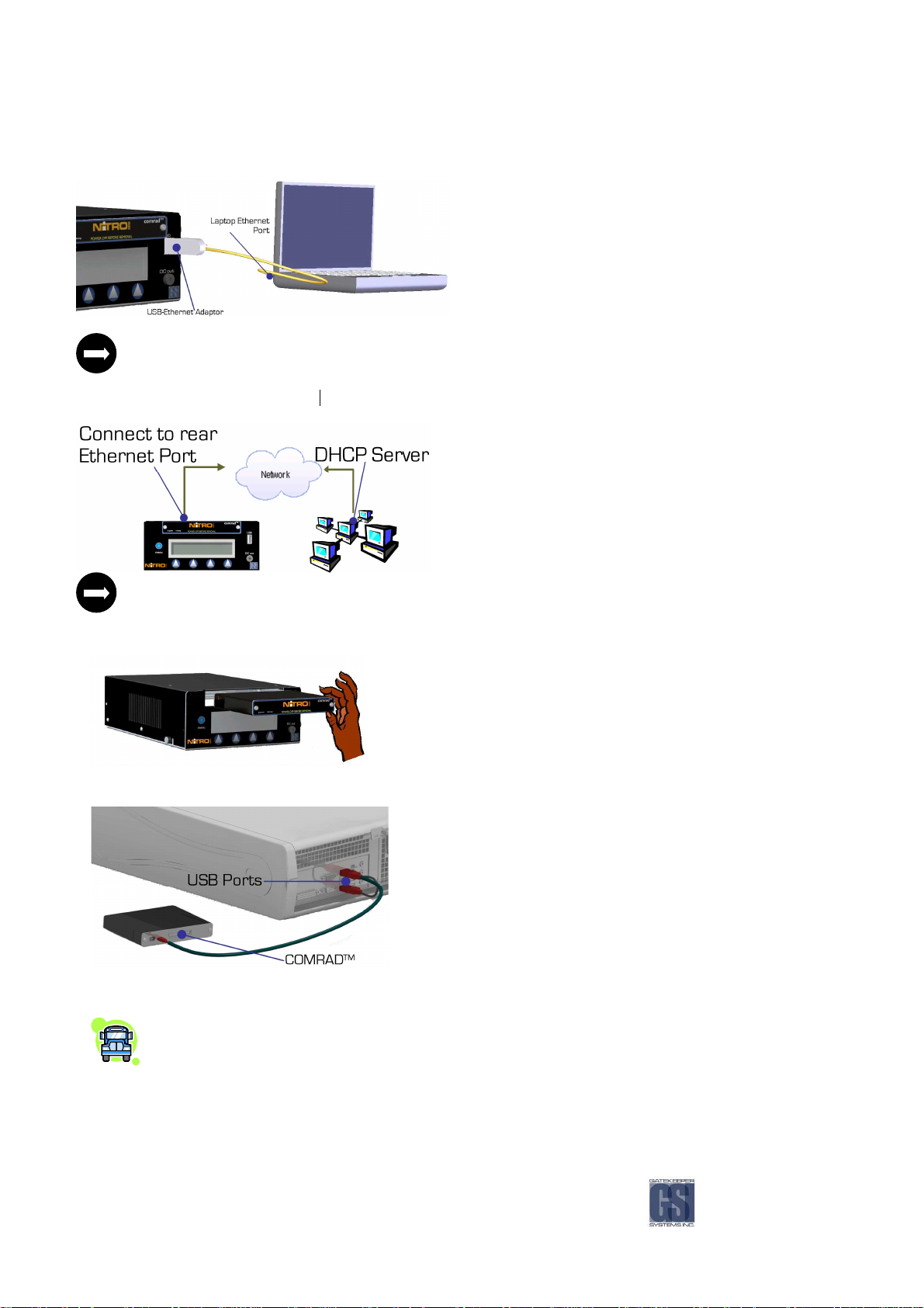
Connecting the Recorder to a Computer
Connecting the Recorder to a Computer....
Connecting the Recorder to a ComputerConnecting the Recorder to a Computer
The NiTRO™ unit acts as a DHCP Server through the USB Ethernet. A DHCP Client on the Laptop/PC is required
for the Laptop/PC to obtain an IP automatically.
Recorder to Local Area Network (LAN)
Recorder to Local Area Network (LAN) .
Recorder to Local Area Network (LAN)Recorder to Local Area Network (LAN)
You will need:
You will need:
You will need:You will need:
NiTRO™ 900 Recorder
USB–Ethernet Adaptor
Crossover Cable
PC with Ethernet port
You will need:
You will need:
You will need:You will need:
NiTRO™ 900 Recorder
Ethernet Cable
LAN connection port
A DHCP Server is required on the Local Area Network for the NiTRO™ unit to obtain an IP automatically through
the rear Ethernet port.
comrad
comrad™ Only to Computer
comradcomrad
Figure
Figure 22
Figure Figure
Figure
Figure 23
Figure Figure
™ Only to Computer....
™ Only to Computer™ Only to Computer
Power down the recorder and remove the comrad™ unit by pulling
firmly on the front.
22:
: comrad
comrad™™™™ Removal
2222
: :
comradcomrad
23:
: comrad
comrad™ to PC via USB
2323
: :
comradcomrad
If the comrad™ is connected to a PC for the first time, it will initiate MAXVIEW™ Installation. Subsequent connections will
automatically open MAXVIEW™. Refer to MAXVIEW™ section for details.
Removal....
Removal Removal
Insert both heads of the Dual Head USB Cable into the USB ports on
your computer. Connect the mini end of the USB cable into the USB
port on the back of the comrad™.
™ to PC via USB....
™ to PC via USB™ to PC via USB
If the Dual Head USB Cable does not provide enough power for the comrad, also insert the DC plug from the
comrad™ Power Supply to the DC Jack (VDC-IN) on the back of the comrad™. Plug the other end of the
power supply to a wall outlet.
-37-

MAXVIEW™ will not automatically open in Windows Vista and restricted Windows XP setups. Please see
Manually Installing the Viewer on Page 52.
Manually Installing
Manually Installing MAXVIEW
Manually Installing Manually Installing
MAXVIEW™ will not automatically open in Windows Vista and restricted Windows XP setups when the comrad™ is plugged
into the PC. To manually install MAXVIEW™, open Windows Explorer by right clicking with your mouse on the START menu
and selecting Explore.
Locate the NiTRO comrad™ in Windows Explorer.
1.
1. Address Bar
Address Bar
1.1.
Address BarAddress Bar
2.
2. setup.exe
setup.exe
2.2.
setup.exesetup.exe
MAXVIEW™™™™....
MAXVIEWMAXVIEW
Figure
Figure 24
24:
: Manually Installing
Figure Figure
Once you have located the NiTRO™ comrad™ in Windows Explorer, double click on the NiTRO™ comrad™
Install MAXVIEW™ software by double clicking on the setup.exe file. Refer to MAXVIEW™ Installation section for details on
installing the viewer. When the installation is complete, MAXVIEW™ will automatically open with all video files
Connecting the Recorder to Computer
Connecting the Recorder to Computer with USB Ethernet Adaptor
Connecting the Recorder to ComputerConnecting the Recorder to Computer
In a laptop environment, (No DHCP Lan services), the recorder will have its own IP Network Address of 192.168.1.1 and it
will provide the laptop unit with an IP address of 192.168.1.64. In Windows Explorer, use the address location:
\\192.168.1.1 to connect to the recorder. See below for detailed instructions. In a Laptop environment (no DHCP LAN
services) the recorder will have its own IP Network.
Manually Installing MAXVIEW
2424
: :
Manually Installing Manually Installing
For first time connection, you will need to install MAXVIEW™ software by double clicking on the setup.exe
Refer to MAXVIEW™ Installation section for details on installing the viewer.
If MAXVIEW™ is installed you can double click my.gsx
comrad™
The NiTRO™ unit acts as a DHCP Server through the USB Ethernet. A DHCP Client on the Laptop/PC is
required for the Laptop/PC to obtain an IP automatically.
Power up the recorder.
Connect one end of the crossover cable to the laptop Ethernet port.
Insert the other end of the crossover cable to the USB Adaptor’s Ethernet port.
MAXVIEW™™™™....
MAXVIEWMAXVIEW
my.gsx to launch MAXVIEW™ and load all the video files on the
my.gsx my.gsx
with USB Ethernet Adaptor....
with USB Ethernet Adaptor with USB Ethernet Adaptor
setup.exe file.
setup.exesetup.exe
-38-

Browsing the Recorder on a Computer
Browsing the Recorder on a Computer....
Browsing the Recorder on a ComputerBrowsing the Recorder on a Computer
Once the recorder is connected to the laptop or desktop, open Windows Explorer by right clicking with your mouse on the
START menu and selecting Explore.
In the address bar type \\ followed by the IP Address 192.168.1.1 and press Enter. To view the IP address go to
Configuration >> System >> IP1
1. Address Bar
2. setup.exe
Connect the USB Adaptor to the USB
During the detection process there should be three audible beeps.
The Local Area Connection is now active.
CAT 5 Crossover Cable
USB to Ethernet Adaptor
USB----AAAA port on the front of the recorder.
USBUSB
Figure
Figure 25
25:
: Browsing The Recorder On A Computer.
Figure Figure
Once Windows Explorer finds the IP address, double click on the NiTRO™ folder.
Recorder to Local Area N
Recorder to Local Area Network (LAN)
Recorder to Local Area NRecorder to Local Area N
Browsing The Recorder On A Computer.
2525
: :
Browsing The Recorder On A Computer.Browsing The Recorder On A Computer.
MAXVIEW™ will not auto start when connecting to the NiTRO™ unit through network share.
For first time connection, you will need to install MAXVIEW™ software by double clicking on the setup.exe file.
Refer to MAXVIEW™ Installation section for details on installing the viewer.
etwork (LAN)....
etwork (LAN)etwork (LAN)
Connect the Cat5 Ethernet Cable to the Ethernet port on the back of the
recorder
Connect the other end of the Ethernet cable to the office Local Area
Connection (LAN).
-39-

LED lights adjacent to the Ethernet connector will light yellow or green indicating proper cabling.
During the detection process there should be a few audible beeps.
The Local Area Connection is now active
On the front LCD panel of the recorder scroll to Configuration >> System >>IP0
should be displayed, e.g. 192.168.0.1
Windows Explorer (e.g.
e.g. 192.168.0.172
e.g. 192.168.0.1e.g. 192.168.0.1
e.g. \\192.168.0.1
192.168.0.172
e.g. e.g.
192.168.0.1192.168.0.1
72
7272
72 ).
7272
Configuration >> System >>IP0 to locate the IP address. The IP Address
Configuration >> System >>IP0Configuration >> System >>IP0
Simply enter two backslashes followed by that address into the address bar in
1.
1. Address
Address
1.1.
AddressAddress
2.
2. setup.exe
setup.exe
2.2.
setup.exesetup.exe
Figure
Figure 26
26:
: Recorder To Local Area Network.
Figure Figure
Recorder To Local Area Network.
2626
: :
Recorder To Local Area Network.Recorder To Local Area Network.
The \\ backslashes are important. There is no "http://", as this is not a web service, but a network share.
MAXVIEW™ will not auto start when connecting to the NiTRO™ unit through network share.
-40-

MAXVIEW
MAXVIEW™™™™....
MAXVIEWMAXVIEW
PC Requirements
PC Requirements....
PC RequirementsPC Requirements
For optimal performance MAXVIEW™ requires the following minimum requirements to operate on a computer:
CCCC
OMPONENT
OMPONENT
OMPONENT OMPONENT
Ope
Operating system
rating system MS Windows XP \Vista
OpeOpe
rating systemrating system
Processor
Processor Intel\AMD, 2GHz processor
ProcessorProcessor
RAM
RAM 256 megabytes (MB) or higher
RAMRAM
Free hard disk space
Free hard disk space 1 GB
Free hard disk spaceFree hard disk space
Monitor
Monitor SVGA 1024 x 768 x 32 bit true color
MonitorMonitor
Video Adaptor
Video Adaptor 3D accelerated graphics processor with 32 MB dedicated video RAM
Video AdaptorVideo Adaptor
Connection
Connection USB 1.1, USB 2.0
ConnectionConnection
For best system performance, we recommend that your PC exceeds these minimum requirements.
MMMM
NOTE: A horizontal resolution of 1440 is required for use of GPS
mapping.
100 Mbps Ethernet Network Card
TCP/IP Protocol
INIMUM
INIMUM
INIMUM INIMUM
RRRR
EQUIREMENTS
EQUIREMENTS
EQUIREMENTS EQUIREMENTS
20GB–100GB of free space is highly recommended to store video data on the PC.
Installation
Installation....
InstallationInstallation
The recorder comes equipped with custom video viewer software (MAXVIEW™) to easily navigate, view and save video files
on your PC. To install MAXVIEW™ software on your PC, connect a comrad™ by following the steps under the comrad™ Only
to Computer section. Once the comrad™ is connected to your PC, the software installation automatically runs. The
installation process is simple and interactive. Follow the directions on each installation screen as it appears to complete
the entire installation process.
For optimal performance, we recommend that you close all other applications while installing and using
MAXVIEW™.
MAXVIEW™ might not automatically open in Windows Vista and restricted Windows XP setups.
-41-

Connect
Connect comrad
Connect Connect
comrad™ to Computer via USB
comradcomrad
™ to Computer via USB....
™ to Computer via USB™ to Computer via USB
Windows XP.
If the screen to the left does not automatically pop up, browse
using Windows Explorer and double click on the removable drive
“GSX NiTRO Videos” and double click on the setup.exe
begin installation. Refer to page 52.
setup.exe file to
setup.exesetup.exe
Installation process:
Software that needs to be installed on your PC will automatically
be checked off, press Next to proceed.
-42-

Choose destination folder:
We recommend that the software is installed under Program
Files, press Next to proceed.
Start Installation:
Press Next to proceed.
Installing Files:
We recommend you do not abort installation process after file
copying has started.
-43-
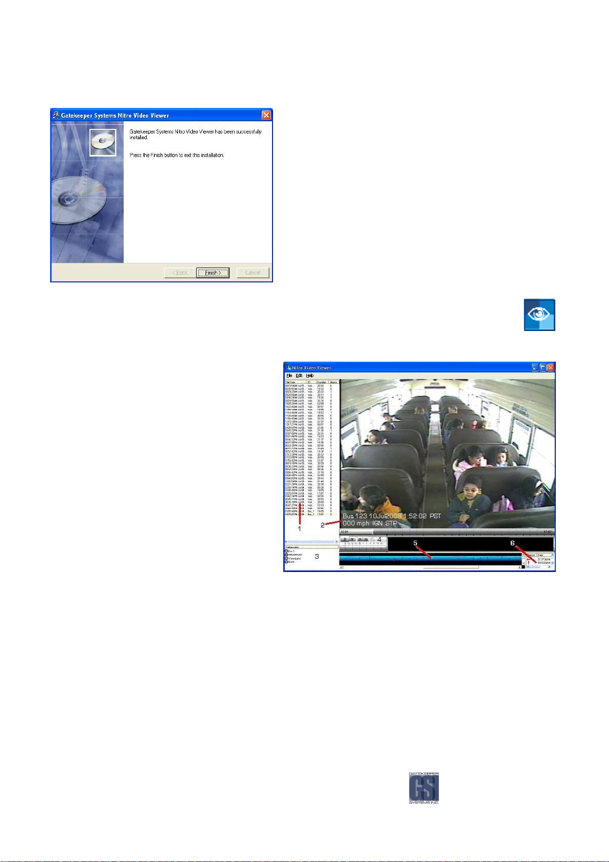
Installation Complete:
Press Finish to complete installation. You may be required to
restart your computer.
Installing MAXVIEW™ video viewer will place the following shortcut on your desktop.
Operation.
Operation.
Operation.Operation.
1. Video File List, this is the default view. If you wish
to change to Calendar View, see Page 63
2. Subtitle Display.
3. Configuration List, double click to setup
configuration.
4. Video Control Panel.
5. Time Graph with speed and sensor display.
Mark & Save video clips and extract still images.
6. Sensor List.
Figure
Figure 27
27:
: MAXVIEW
Figure Figure
Opening Video Files.
Opening Video Files.
Opening Video Files.Opening Video Files.
You can open individual video files in MAXVIEW™.
When connecting a comrad™ to your PC via USB, MAXVIEW™ should automatically open and load all videos. If it does not
automatically open, browse to the location and double click on the my.gsx file. This will open MAXVIEW™ with all video files
loaded.
-44-
MAXVIEW™™™™ Operation.
2727
: :
MAXVIEWMAXVIEW
1. Double click on the MAXVIEW™ icon located on your desktop.
2. Choose File, select Open.
3. Choose location where files are located..
4. Select video file(s).
5. Press Open.
Operation.
Operation.Operation.

GPS.
GPS.
GPS.GPS.
Please Note: Only NiTRO™ 900 systems which had a GPS module fitted at time of manufacture can use this feature of
MAXVIEW™. Additionally an active internet connection is required to view the GPS data window.
As can be seen in Figure 28 there are
three views which can be chosen. The default is the MAP view,
this default option cannot be changed. To view Hybrid or
Satellite images, click on the name in the top right-hand corner
of the Map window. The Vehicle Locator is shown as an inverted
Green triangle. The Vehicle Locator will only display when
enabled and when video playback is paused. When you press
the Play button, the Vehicle Locator will be removed from the
map until video
playback is paused again.”
Figure
Figure 28
28:
: Composite of Map; Sa
Figure Figure
Figure
Figure 29
Figure Figure
Composite of Map; Satellite and Hybrid Views.
2828
: :
Composite of Map; SaComposite of Map; Sa
29:::: Displaying The GPS Map.
Displaying The GPS Map.
2929
Displaying The GPS Map. Displaying The GPS Map.
tellite and Hybrid Views.
tellite and Hybrid Views.tellite and Hybrid Views.
With a new install of MAXVIEW™ the default is not to display the GPS map, this
is an option which has to be set. In MAXVIEW™ select the View menu, next
choose GPS Mapping and then select Show Map (Figure 29. This will bring up
the window to the right of the main MAXVIEW™ window. This GPS data
mapping window is moveable and resizable.
To view where the vehicle is in relation to the GPS Mapping select the View
menu go to GPS Mapping, select Show Vehicle Locator (Figure 30 This will
display the inverted Green triangle.
Figure
Figure 30
30: Displaying The
Figure Figure
Using The
Using The GPS
Using The Using The
: Displaying The GPS
3030
: Displaying The : Displaying The
If you do not see the vehicle marker please check these potential reasons prior to calling technical support.
There is no GPS data at the time when the video is paused; There is GPS data at that time but the signal is too
weak to place the marker on the map; The marker is on the map but not on the current visible area of the map;
The map window is not open.
GPS Zoom Feature.
GPS GPS
GPS Vehicle Locator.
Vehicle Locator.
GPS GPS
Vehicle Locator.Vehicle Locator.
Zoom Feature.
Zoom Feature.Zoom Feature.
When viewing the Vehicle Locator if you wish to zoom-in there are two ways with
which to achieve this:
1) Use the Slider control to the left of the GPS Mapping Window.
2) Place the cursor towards the Vehicle Locator and when it changes to the GRAB
hand, double- click with the left mouse button. This will auto-zoom in on the
image. Continue to do this until the required level of zoom is achieved.
Continued usage will determine which method you personally prefer.
-45-

Using The Scrubber.
Using The Scrubber.
Using The Scrubber.Using The Scrubber.
When searching for a specific incident reported during the run
of the vehicle a useful tool to become familiar with is the
Scrubber. The Scrubber is the vertical bar located in
MAXVIEW™ on the grey bar below the actual video display area.
Once playback is paused (graphic A above right) the Vehicle
Locator will be displayed within MAP view. If you now move the
Scrubber horizontally the Vehicle Locator will change its relevant
position on the map, matching the GPS co-ordinates
displayed in MAXVIEW™ (see graphic B right). Once the required positioning is found it
is now possible to change the GPS Data window to Satellite or Hybrid mode if required
(graphic C on the right). There will be a one or two second delay for the Vehicle
Locator position to be updated.
Time Graph Selection.
Time Graph Selection.
Time Graph Selection.Time Graph Selection.
Another option for viewing GPS location data is to use the Blue Time
Graph bar within MAXVIEW™. With playback video paused double-left
click on the Time Graph and the Vehicle Locator will appear in the GPS
Data window.
With the playback video still paused, if you left click again in a different
position along the Time Graph the Vehicle Locator will move to the
corresponding GPS data co-ordinates, there will be a one or two second
delay for the Vehicle Locator
position to be updated.
Using The Calendar Feature.
Using The Calendar Feature.
Using The Calendar Feature.Using The Calendar Feature.
With MAXVIEW™ you can use a calendar feature to choose which date/time video clip you wish to view. This feature offers
a distinct advantage when you are trying to find a specific incident which has been reported.
When using MAXVIEW™, choose the View Menu and from there select Clip Filter and finally
By Date.
The Calendar window can be broken down into three major parts:
1. The date of the current video being displayed in MAXVIEW™.
Figure
Figure 31
31: Using the Calendar Feature.
Figure Figure
: Using the Calendar Feature.
3131
: Using the Calendar Feature.: Using the Calendar Feature.
2. The Dates in BOLD
chosen as the selected view.
3. In this section there is a breakdown of the video information, such as, Time; Date; Bus
ID, etc.
BOLD reflect the dates for which there is captured video and which can be
BOLDBOLD
-46-
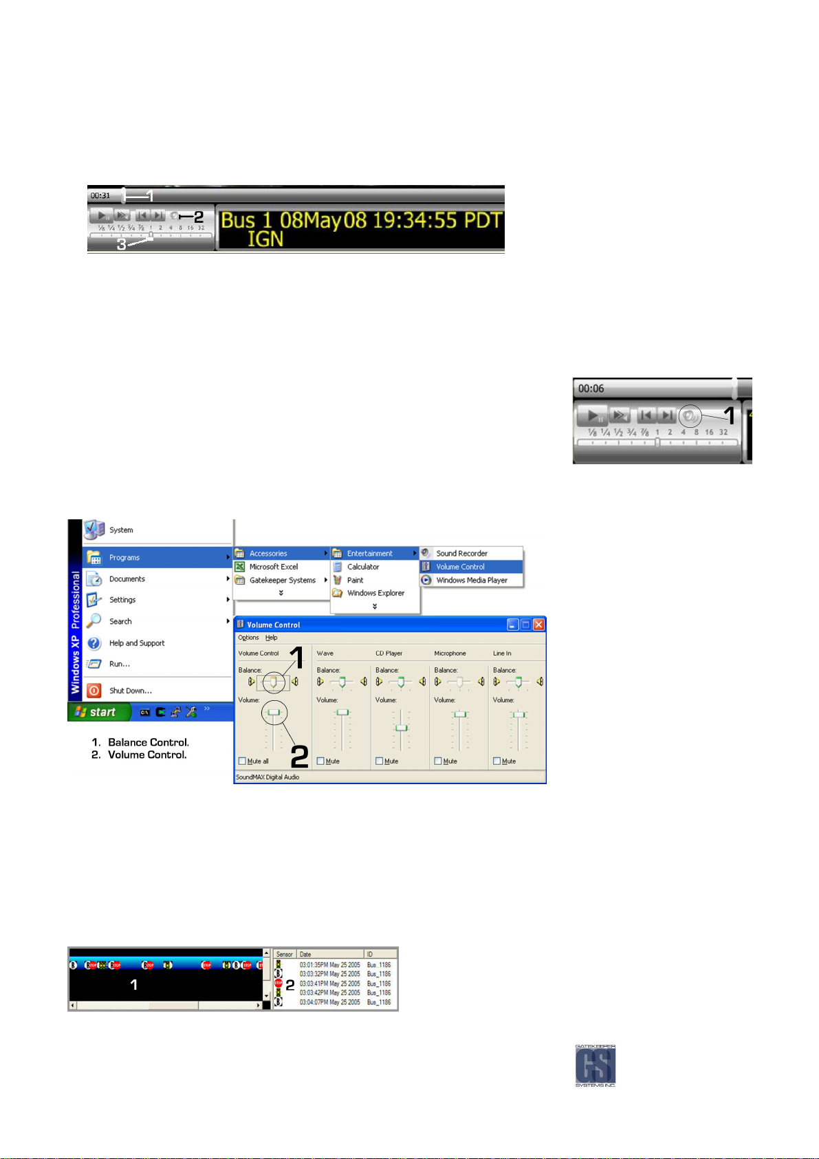
1. Slider Bar, drag with mouse to move backwards and forwards.
2. Speaker, use to mute sound. There may be a slight delay before sound is actually muted.
3. Adjust Playback Speed, (you will only hear audio when slider is set to 1).
Figure
Figure 32
32: Adjusting Playback Speed.
Figure Figure
Audio Cont
Audio Controls.
Audio ContAudio Cont
: Adjusting Playback Speed.
3232
: Adjusting Playback Speed.: Adjusting Playback Speed.
rols.
rols.rols.
You can turn Audio on/off by clicking the Speaker Icon, (1), located in the Video Control
Panel. There may be a slight time delay of 2-3 seconds before audio is muted or
audible.
Using the Balance control in Windows Volume Control, located in “Start Menu > Programs > Accessories > Entertainment >
Volume Control”, you can control how loud each audio channel is. This is useful if, for example, the sound from one camera
is so loud that the sound from the other camera can’t be heard.
Figure
Figure 33
33: Adjusting Sound Balance In Windows XP
Figure Figure
Displaying Sensors.
Displaying Sensors.
Displaying Sensors.Displaying Sensors.
: Adjusting Sound Balance In Windows XP....
3333
: Adjusting Sound Balance In Windows XP: Adjusting Sound Balance In Windows XP
You can choose to have sensors appear in the Video Clip Graph at the time they were triggered.
1. Choose Edit.
2. Choose Options.
3. Place a check in the box for each trigger you want to appear on the Video Clip Graph.
4. Press Apply.
5.
Press Ok.
1. Click on any Sensor to move to that point in the video
2. Click on any Sensor to move to that point in the video.
-47-

You can choose to ignore all sensors when loading video. If you choose this option, the next time MAXVIEW™ is loaded, the
sensor list will appear empty. Doing this may decrease the amount of time it takes to load video files.
1. Choose Edit.
2. Choose Options.
3. Put a check in the box “Ignore sensors when loading video”.
4. Press Apply.
5. Press Ok.
If you find that none of your sensor icons are appearing on the blue bar, make sure that the icons are checked off
to appear. To confirm, go to Edit >> Options and make sure the icon boxes are checked.
Drag and Drop a Video File.
Drag and Drop a Video File.
Drag and Drop a Video File.Drag and Drop a Video File.
You can drag and drop an entire video file into another location, i.e.: Desktop. To do this Left-click on video file in the Video
File and Clip list. Next Drag to your desktop and finally Release the mouse button.
Mark & Save a Video Clip.
Mark & Save a Video Clip.
Mark & Save a Video Clip.Mark & Save a Video Clip.
There are two ways in which you can Save a video clip, one using the right-mouse button and the other method uses the File
Menu. Both methods use the same steps to first mark the video you wish to take a clip of:
1. Pause the video at beginning of the clip you want to save.
2. Left-click on the Video Clip Graph where the yellow cursor is located.
3. Drag mouse to the right, the graph will be highlighted in green.
4. Release mouse at end point.
5. Right-click on graph, choose Save Clip or Email Clip, or choose File, Save>Video Clip.
1. Selected video clip to save.
2. Right click with mouse, or go to the file menu,
to Save or Email video clip or still image.
3. Information on length of clip and file size.
Figure
Figure 34
34: Mark and Save Clips.
Figure Figure
Extracting Still Image.
Extracting Still Image.
Extracting Still Image.Extracting Still Image.
You can extract a still image (jpeg) using the blue Video Clip Graph, this process is very similar to saving a video clip.
: Mark and Save Clips.
3434
: Mark and Save Clips.: Mark and Save Clips.
1. Pause Video at the point where you want to extract an image.
2. Right-click on the Video Clip Graph and choose “Save still image” or “Email still image”.
3. Or choose File, Save> Still image (see Figure 35).
4. This will bring up, in the case of Save Still Image, a standard Save As… Windows dialog box.
5. By default, the file name will be the ID followed by a hyphen followed by Year; Month; Day, e.g. 1234-20091101.jpg,
(.JPG is a standard graphic file extension viewable on all computers.)
-48-

Figure
Figure 35
35: Save A Still Image.
Figure Figure
Setting the Recorder Configuration.
Setting the Recorder Configuration.
Setting the Recorder Configuration.Setting the Recorder Configuration.
You can set up the recorder configuration using MAXVIEW™ rather than the LCD screen. To open the configuration menu
first Double-click on the file located in the configuration list.
For details on any of the configuration settings, refer to Setting the Configuration section starting on page 27.
General Configuration.
: Save A Still Image.
3535
: Save A Still Image.: Save A Still Image.
The filename is the ID name and by default is the factory serial number. Each ID that has
been set will be listed in the Configuration list.
In this screen you set the following configurations:
ID
Startup Mode
Time Zone
Units
Pulses Per Unit
Volume Out
-49-

Recording Configuration.
In the Recording Tab set the following configurations:
Audio
Volume In
Max Cameras
Record Delay
Record Extend
Dwell Time
Sensor Configuration
You can change the name of each sensor from the default
name. Also assign a specific sensor to a specific camera.
Please remember that the Alarm Button is connected to
sensor 2 (ALM)
.
-50-

Video Configuration.
In the Video Screen, the following
options are available for
customization:
Record Quality
Frames Per Second
Video Standard
Subtitle Position
Color; Black/White camera
selection.
Please note: When setting the video
to Color or to Black and White, if
there are multiple cameras
connected to the NiTRO™ 900 with
one being a color camera, this
setting must be set to Color or all
output will be Black and White
Network Configuration.
In Network Configuration you can assign a time interval, between 5
minutes and 30 minutes, for the DHCP Refresh rate.
-51-
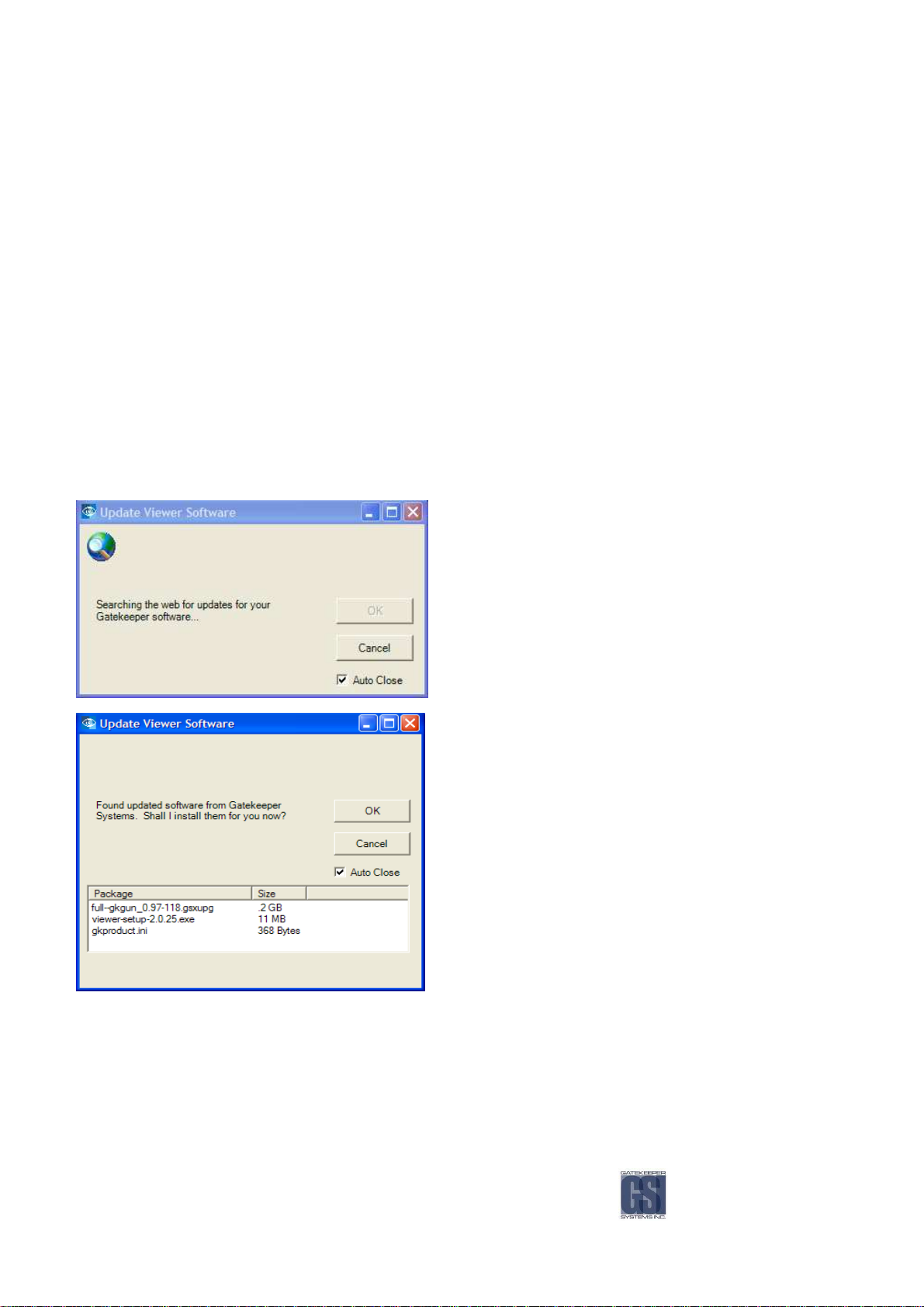
Saving Configuration.
Saving Configuration.
Saving Configuration.Saving Configuration.
Save the new configuration file on to the comrad™ in the Config folder. In this case, the file will be saved as “4063D4FBBF”.
Loading Configuration on Recorder.
Loading Configuration on Recorder.
Loading Configuration on Recorder.Loading Configuration on Recorder.
After you have saved the configuration you must load it if you wish the ID to become active.
Power up the recorder and Go to Configuration, press Go.
Go to Basic and press Go.
Next choose Load ID and press Go.
Use the + and – signs to scroll to the desired configuration file.
Finally press the blue menu button to load.
All files recorded from this point forward will use this configuration.
Check for Updates..
Check for Updates..
Check for Updates..Check for Updates..
New software updates can be downloaded automatically MAXVIEW™. All software updates are cumulative. The most
recent software update for the recorder will incorporate any changes introduced by previous versions.
Make sure that the computer has an internet
connection.
Do not start MAXVIEW™ manually (Using Desktop
Icon).
Plug the comrad™ into your computer through the
USB port. See comrad™ only to Computer section
for more details. MAXVIEW™ will automatically Open
and start running.
Choose File… Check for Updates.
Press OK to download updates to the comrad™.
-52-

Files are automatically downloaded to your PC.
Upgrade files are automatically copied in to the upgrade
folder on the comrad™.
comrad™ has been successfully upgraded, you may
now update another comrad™ or use this comrad™
to copy upgrade files to another recorder.
Refer to the Upgrading Software on the NiTRO™ 900
for details.
-53-

Upgrading Software on the
Upgrading Software on the NiTRO
Upgrading Software on the Upgrading Software on the
To upgrade each recorder, follow the instructions under “Check for Updates” above first to download the upgrade files to a
comrad™. Once that is complete follow the instructions below.
Plug in the comrad™ as an external drive.
Any upgrades will be automatically copied to the NiTRO™ 900. The LCD will display “Copying
Upgrades” for a moment.
When the upgrade files are finished copying, shutdown and restart the recorder.
To verify that the upgrade was successful, go to Configuration >> System >> S/W Version
and verify that the number is the same as the upgrade file downloaded.
NiTRO™™™™ 900
NiTRONiTRO
900....
900 900
Dual Head
USB Cable
Spare
comradTM
Figure
Figure 36
36: Upgradi
Figure Figure
3636
comradTM
DC – DC Cable
: Upgrading Software.
: Upgradi: Upgradi
ng Software.
ng Software.ng Software.
Ensure that the NiTRO™ System has a constant and stable power source. If power is
removed from the unit, secure stable power and repeat the process.
-54-

Troubleshooting
Troubleshooting....
TroubleshootingTroubleshooting
When I turn on the Bus, my recorder won’t power up or my recorder powers up and then shuts down every
When I turn on the Bus, my recorder won’t power up or my recorder powers up and then shuts down every couple of
When I turn on the Bus, my recorder won’t power up or my recorder powers up and then shuts down every When I turn on the Bus, my recorder won’t power up or my recorder powers up and then shuts down every
minutes. Why is this?
minutes. Why is this?
minutes. Why is this?minutes. Why is this?
Ensure that the Sensor harness is connected correctly
Ensure the black Molex is connected to the back of the recorder
Ensure comrad™ is properly inserted into the NiTRO™ Control unit
My camera shows
My camera shows an upside down image:
My camera shows My camera shows
The camera is meant to be mounted to the ceiling. If the camera is mounted right side up, or sideways, the preview
will show an image that is rotated.
Rotate the lens by removing the two large screws on the camera bracket, rotating the camera bracket 180° and
then screwing it back on.
When I view vi
When I view video, there is only a black
When I view viWhen I view vi
Make sure all camera harnesses are connected to the video in ports on the back of the recorder and/or camera.
I have connected a monitor to my recorder, yet there is nothin
I have connected a monitor to my recorder, yet there is nothing on the screen of the monitor. Why?
I have connected a monitor to my recorder, yet there is nothinI have connected a monitor to my recorder, yet there is nothin
If the monitor uses an S-video connector, the monitor needs to be connected to the unit prior to starting the unit.
I have
I have MAXVIEW
MAXVIEW™™™™ open and want to view a video file. How do I do this?
I have I have
MAXVIEWMAXVIEW
Click on File > Open.
Using the drop down menu under “Look in”, locate NiTRO Videos.
Double click on ‘videos’ folder (Select ‘clips’ folder if applicable).
Select desired video file(s) to view by clicking with mouse to highlight and then press Open.
If you rename the video file make sure you put the right extension at the end of the file (.avi)
an upside down image:
an upside down image:an upside down image:
deo, there is only a black screen:
deo, there is only a black deo, there is only a black
open and want to view a video file. How do I do this?
open and want to view a video file. How do I do this?open and want to view a video file. How do I do this?
screen:
screen:screen:
g on the screen of the monitor. Why?
g on the screen of the monitor. Why?g on the screen of the monitor. Why?
(.avi); Example: my clip
; Example: my clip.avi
(.avi)(.avi)
; Example: my clip; Example: my clip
couple of
couple of couple of
.avi
.avi.avi
-55-

Appendix
Setting The System ID
Setting The System ID
Setting The System IDSetting The System ID
Once the system has booted and is in Record mode, press the button directly
below either the Right or Left pointing arrow until you see Configuration. Press
the GO button.
Cycle through the options until you see Basic listed, Press the GO button.
Cycle through these options until you see Set ID, Press the GO button.
Clear the long serial number from the screen by pressing the ‘-‘ button. To
change a character use the + and – buttons to cycle through until you see the
character you require. Use the Left and Right arrow button to advance or go
back. Repeat this sequence until you have the desired name. To create a space
cycle through the characters until the end of all the lower case letters.
Once the ID has been set, press the BLUE menu button to the left of the LCD.
Once the BLUE menu button has been pressed you will see the screen change to
Saving Config.
A confirmation screen will appear stating Config Saved. Continue through the
BASIC menu to change and confirm all parameters you need.
Main Power Harness.
Main Power Harness.
Main Power Harness.Main Power Harness.
The Main Power Harness Cable contains two wires
A Negative Wire. B Positive Wire.
Please ensure Main Power Cable is hooked up before any battery cut-off or isolation circuits.
A.
A. Hook the Black wire directly to the Negative Battery
A.A.
Terminal.
B.
B. Connect the RED wire directly to the Positive Battery
B.B.
Terminal. Ensure that the 15 AMP fuse is in-line
between the Red wire and the Positive Battery
Terminal.
NOTE:
NOTE: The 15 AMP Fuse must be pulled when jump starting the bus battery, or, when doing electrical work. Failure to
NOTE:NOTE:
comply with these instructions may result in the warranty being voided.
-56-

Sensor Harness Cable (C
Sensor Harness Cable (CAB000145)
Sensor Harness Cable (CSensor Harness Cable (C
The Sensor Harness Cable is made up of three separate inner-core cables; AAAA Trigger (7 wires); BBBB Alarm & LED (4 wires); CCCC
Speed (3 wires)
A. Trigger Sensor Harness.
A. Trigger Sensor Harness.
A. Trigger Sensor Harness.A. Trigger Sensor Harness.
1. Red. Connect to accessory 12V+ . Provides ignition to Digital Video
Recorder. DO Not connect to noise suppression circuit, connect to true
Ignition source.
2. Yellow. Connect to Stop Arm (8 way) circuit 12V+
3. Blue. User customizable sensor (optional) 12V+
4. Green. User customizable sensor (optional) 12V+
5. Orange. Connect to Brake light circuit 12V+.
6. Brown. User customizable sensor (optional) 12V+
7. White. Connect to Warning light (Amber) circuit, 12V+.
B.
B. Alarm & LED
Alarm & LED Harness
B.B.
Alarm & LED Alarm & LED
1. Red. 12V+ output from unit. Connect to Red wires from Alarm Button and Record LED. Do Not
signal.
2. Green. Connect to White wire from Record LED.
3. Black. Connect to Black wire from Alarm button.
4. White. (Optional), connect to 12V Driver Alarm Buzzer or Light Accessory
Harness (4 wires):
HarnessHarness
AB000145)
AB000145)AB000145)
Do Not hook-up to 12V Input
Do NotDo Not
C. Speed
C. Speed Sensor Harness
C. Speed C. Speed
1. Green. Connect to Speed Pulse. (See transmission or ABS electrical manual for your vehicle.
2. Red. Output from Digital Video Recorder, (Only to be used with Speedometer Interface Modules)
3. Black. Ground Signal ( - ) from Digital Video Recorder. (Only to be used with Speedometer Interface Modules)
Sensor Harness (3 wires), Not required with GPS.
Sensor HarnessSensor Harness
-57-

Notes
Notes....
NotesNotes
-58-

-59-

-60-

Warranty
Warranty....
WarrantyWarranty
Customer Limited Warranty
GATEKEEPER SYSTEMS INC.
GATEKEEPER SYSTEMS INC. (Company) warrants that any product
GATEKEEPER SYSTEMS INC.GATEKEEPER SYSTEMS INC.
manufactured or supplied by Gatekeeper Systems and found in the
reasonable judgment of Gatekeeper Systems to be defective in material
or workmanship will be repaired or replaced by Gatekeeper Systems
without charge for parts and labor.
This warranty shall cover the following periods and equipment:
Camcorder System
Camcorder System
Camcorder System Camcorder System
Cameras - 1 year
Battery Adapters - 1 year
Plates & Enclosure Boxes - lifetime
Gatekeeper System
Gatekeeper System
Gatekeeper System Gatekeeper System
Interior Cameras - 5 years
Exterior Cameras - 3 years
VCR - 1 year
GSX-900 / 1000 Digital Recorder - 1year
NiTRO-900 / 1000 Digital Recorder – 5 years (hard drives limited to 3
years)
Nitro 401 and Nitro 404 Digital Recorder – 3 years
Kingston SDHC Memory Card – Lifetime
All Accessories - 1 year
The warranty periods commence on the date of shipment. During the
period of the warranty the Company, at its discretion will repair and/or
replace all improperly functioning equipment caused by a
manufacturer’s defect.
accidental or intentional damage, vehicle electrical systems generating
steady state or transients, voltages or currents exceeding product
specification, loss, acts of nature, water damage, or any other event
that did not originate during the manufacturer of the product. DVR’s
must be returned once every twelve months for service otherwise
warranty may be void.
This warranty does not protect against
Gatekeeper Systems’ is not responsible for lost or missing
video.
The warranty does not extend to repairs made necessary by
normal wear or by the use of parts or accessories which are either
incompatible with the Company product or adversely affect its
operation, performance or durability.
Gatekeeper Systems reserves the right to change or improve the
design of any Company product without assuming any obligation to
modify any product previously manufactured.
ALL IMPLIED WARRANTIES ARE LIMITED IN DURATION TO THE
SPECIFIED PERIOD FOR EACH PRODUCT CATEGORY AS LISTED IN THIS
DOCUMENT. ACCORDINGLY, ANY SUCH IMPLIED WARRANTIES
INCLUDING MERCHANTABILITY, FITNESS FOR A PARTICULAR
PURPOSE, OR OTHERWISE, ARE DISCLAIMED IN THEIR ENTIRETY
AFTER THE EXPIRATION OF THE APPROPRIATE WARRANTY
PERIOD. GATEKEEPER SYSTEMS’ OBLIGATION UNDER THIS
WARRANTY IS STRICTLY AND EXCLUSIVELY LIMITED TO THE REPAIR
OR REPLACEMENT OF DEFECTIVE PARTS, AND GATEKEEPER
SYSTEMS DOES NOT ASSUME OR AUTHORIZE ANYONE TO ASSUME
FOR THEM ANY OTHER OBLIGATION.
GATEKEEPER SYSTEMS ASSUMES NO RESPONSIBILITY FOR
INCIDENTAL, CONSEQUENTIAL OR OTHER DAMAGES INCLUDING,
BUT NOT LIMITED TO THE EXPENSE OF RETURNING THE COMPANY
PRODUCT TO GATEKEEPER SYSTEMS CORPORATE HEAD OFFICE,
MECHANIC’S TRAVEL TIME, CUSTOMER LABOR EXPENSES,
TELEPHONE OR TELEGRAM CHARGES, RENTAL OF LIKE PRODUCT
DURING THE TIME WARRANTY SERVICE IS BEING PERFORMED,
TRAVEL, LOSS OF USE OF THE PRODUCT, LOSS OF TIME OR
INCONVENIENCE.
The Gatekeeper Systems product including any defective part must be
returned to Gatekeeper Systems within the warranty period. The
expense of delivering Company product to Gatekeeper Systems for
warranty work will be paid by the customer. The expense of
delivering Company product back to the customer will be paid by
Gatekeeper Systems. Gatekeeper Systems’ responsibility in respect to
claims is limited to making the required repairs or replacements and
no claim of breach of warranty shall be cause for cancellation or
rescission of the contract of sale. Proof of purchase complete with the
serial numbers of the products purchased will be required by the
customer to substantiate any warranty claim. All warranty work must
be performed by an authorized Gatekeeper Systems service
representative.
This warranty does not cover any Gatekeeper Systems’ product that
has been subject to misuse, neglect, negligence, or accident, or that has
been operated in any way contrary to the operating instructions as
specified by Gatekeeper Systems either verbally, in writing, by
instructions written on the product or in the Gatekeeper Systems
Installation and Operating Manual. This warranty does not apply to
any damage to the Gatekeeper Systems product that is the result of
improper maintenance or to any Gatekeeper Systems’ product that has
been altered or modified so as to adversely affect the products’
operation, performance or durability or that has been altered or
modified so as to change its intended use.
Warranty Service
Warranty Service
Warranty ServiceWarranty Service
To obtain warranty service, the purchaser must notify the Company
during the warranty period. The Purchaser will discuss the defect or
problem with a Company technician, and once the problem has been
verified the Company will issue a return material authorization number
(RMA) authorizing the purchaser to return faulty merchandise to the
Company for repair or replacement as determined by the Company.
It may be necessary for the customer to assist Gatekeeper Systems
in assessing failed product. Gatekeeper Systems may require the
customer to remove hardware, manipulate software and/or
perform other diagnostic activities. Failure to assist in and allow
remote diagnostic activities may result in a service fee being charged.
Advance replacements will be issued for the first 45 days from the
date of shipment.
This Warranty applies to all Company products manufactured by
Gatekeeper Systems and sold in the United States and
Canada.
This warranty gives you specific legal rights, and you may also have
other rights which vary from state to state.
-61-

USA RECEIVING FACILITY:
Gatekeeper Systems Inc.
446 Harrison Street
Sumas WA 98295
Tel. 1.604.864.6187
Fax 1.604.864.8490
Toll Free (N.A.) 1.888.666.4833
CANADA OPERATIONS:
Gatekeeper Systems Inc.
301-3 1127 Wheel Avenue
Abbotsford BC V2T 6H1
Tel. 1.604.864.6187
Fax. 1.604.864.8490
Toll Free (N.A.) 1.888.666.4833
Contact Information
Contact Information....
Contact InformationContact Information
GSI
GSI –––– Canada
Canada
GSIGSI
Canada Canada
301-31127 Wheel Avenue
Abbotsford, BC V2T 6H1
Canada
GSI
GSI –––– USA
USA
GSIGSI
USA USA
446 Harris Road
Sumas, WA 98295
USA
Sales & Technical Support
Sales & Technical Support
Sales & Technical SupportSales & Technical Support
North America:
North America:
North America: North America:
Tel: 1.604.864.6187
Fax: 1.604.864.8472
Toll Free: 1.888.666.4833
Toll Free: 1.888.666.4833
Toll Free: 1.888.666.4833Toll Free: 1.888.666.4833
Document Revision:
Document Revision:
Document Revision:Document Revision:
October 1st 2010 - Version 1.8.1 – TB00046_SinglePageNitro900_ManualV1.1
 Loading...