


User manual
July 2019
1

Table of Contents
1. Introduction ..................................................................................................................................... 3
2. Basics and safety summary ........................................................................................................... 4
2.1. Safety ...................................................................................................................................................................... 4
2.2. Installation .............................................................................................................................................................. 5
2.3. Usage ....................................................................................................................................................................... 7
3. Firmware editions ........................................................................................................................... 9
4. TITAN Kits ..................................................................................................................................... 13
5. GATE Control Station (GCS) .......................................................................................................... 15
5.1. Connecting TITAN to USB-Link and PC, MAC or Android Device. .....................................................................15
5.2. Status tab .............................................................................................................................................................18
5.3. Settings tab ..........................................................................................................................................................19
5.4. Sensors tab ........................................................................................................................................................... 22
5.5. Statistics tab .........................................................................................................................................................24
5.6. Diagnostic Trouble Codes (DTC) tab ................................................................................................................... 25
6. TITAN V2 ........................................................................................................................................ 26
6.1. TITAN V2 Advanced Set .......................................................................................................................................27
6.2. TITAN V2 Basic Module ........................................................................................................................................ 28
6.3. Installation safety ................................................................................................................................................29
6.4. Installation ............................................................................................................................................................ 34
7. TITAN V3 ........................................................................................................................................ 51
7.1. TITAN Advanced Set ............................................................................................................................................52
7.2. TITAN Basic Module .............................................................................................................................................. 53
7.3. Installation safety ................................................................................................................................................54
7.4. Installation ............................................................................................................................................................ 56
8. TITAN V2 NGRS .............................................................................................................................. 72
8.1. TITAN Advanced Set ............................................................................................................................................73
8.2. TITAN Basic Module .............................................................................................................................................. 74
8.3. Installation safety ................................................................................................................................................75
8.4. Installation ............................................................................................................................................................ 78
9. Functions ....................................................................................................................................... 95
10. Legal Notice ............................................................................................................................... 100
10.1. PRODUCT DISPOSAL INSTRUCTIONS..............................................................................................................101
10.2. CERTIFICATE OF CONFORMITY ........................................................................................................................101
2

1. Introduction
Congratulations on your new TITAN, the rst in the world drop-in AEG Control System with
optical sensors. TITAN will transform your AEG into an advanced training weapon system. Gain
a tactical advantage thanks to the extremely fast trigger response, with an option of adjusting
the AEG for each mission with multiple functions. Give your AEG a new lease of life!
Congure your TITAN in the eld or simply update the rmware and adjust the settings using
the USB-Link and the GATE Control Station app which is available for PC/MAC and Android
devices.
With this guide, you will get familiar with all the functions and learn how to use them.
3

2. Basics and safety summary
Please read this manual before using the device to ensure safe and proper use.
Information contained in this document is subject to updating without notice. Please check if
you have downloaded the latest manual from the Technical Support section of our website:
https://www.gatee.eu/technical-support/manuals
The Product Warranty Form is also available there:
https://www.gatee.eu/technical-support/warranty
GATE Enterprise spółka z ograniczoną odpowiedzialnością sp. k. does not take any
responsibility for damages, injuries and accidents resulting from the use of this product or
the use of Air Electric Gun with the product installed. In case you have any diculties while
installing or using this product, we recommend to contact us. Our support team will answer all
your questions and send you some hints.
In order to contact GATE, you can:
a) email us at titan@gatee.eu
b) contact us via Facebook: www.facebook.com/gatee
c) call (+48) 122-100-523
Warning
Situations that could cause injury to yourself and others.
Caution
Situations that could cause damage to your device or other equipment.
Notice
Notes, usage tips, or additional information.
2.1. Safety
Notice
We recommend that this product should be installed by an experienced
airso service. Before starting installation process, please ensure
that your AEG is empty and there are no BBs inside.
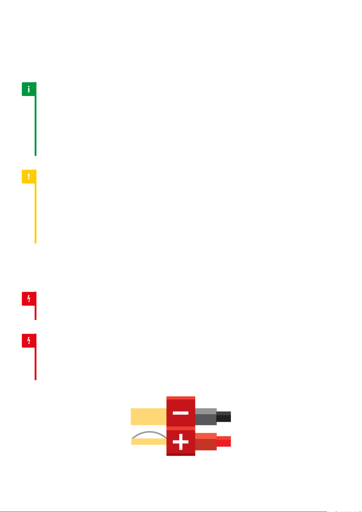
Warning
Incorrectly connecting positive and negative battery terminals will cause
immediate damage to the drop-in module what is not covered by the
warranty and it can lead to re, burn or even battery explosion.
4

Warning
Stay careful to prevent short circuiting the battery as the consequences
can be very dangerous (re, battery explosion, burn).
2.2. Installation
Warning
Before starting installation process, please ensure that
your AEG is empty and there are no BBs inside.
Caution
The incorrect installation may result in sensors’ damage
what is not covered by the warranty.
Caution
Connectors should be bent according to the photo below. Bending
connectors in the opposite direction may cause them to break.
5
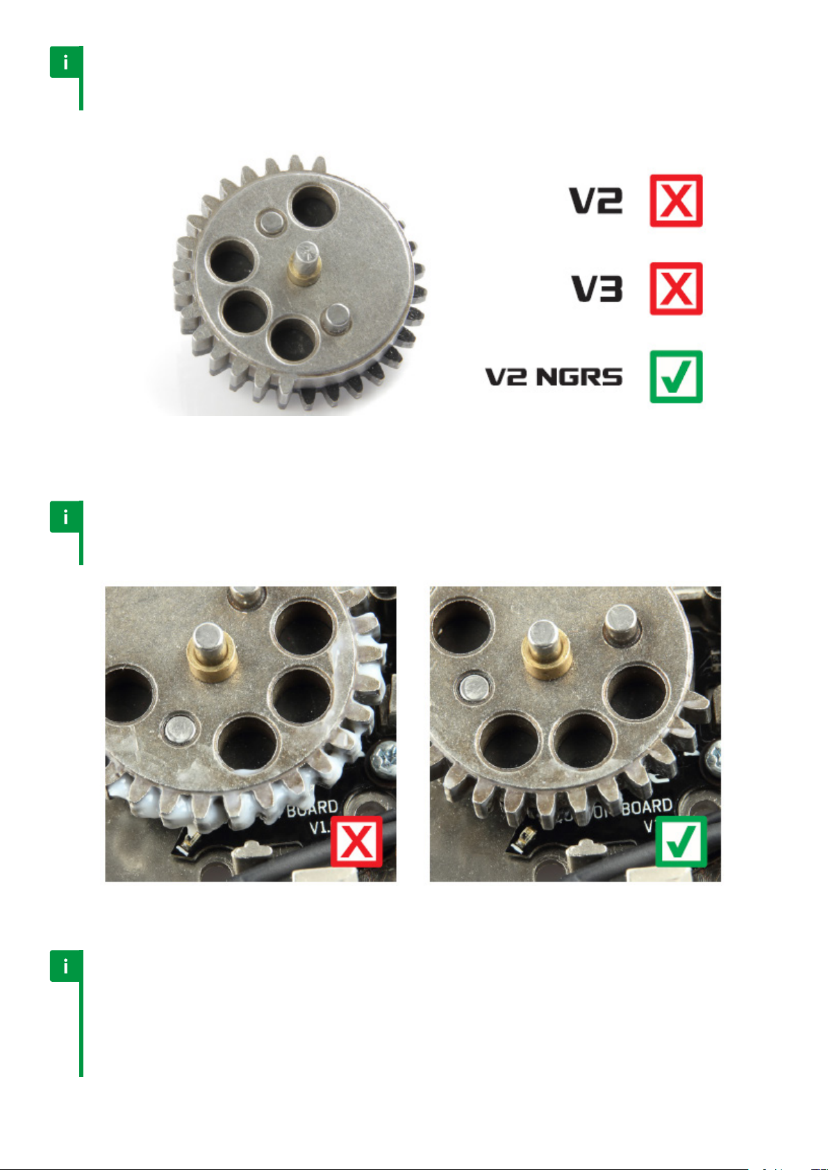
Notice
TITAN V2 and V3 do not support the Innite torque-up gears.
TITAN V2 NGRS supports the Innite torque-up gears.
Notice
Do not use too much grease. Excessive grease may cover gaps
between teeth what will cause improper cycle detection.
Notice
For your own safety, you should install an additional fuse between the battery
and the drop-in module. The fuse should be placed very close to the battery.
It will protect the battery in case of: (1) incorrectly connecting positive and
negative battery terminals; (2) shorting the power cords which connect
battery and TITAN; (3) mechanical damage to the drop-in module.
6

2.3. Usage
Warning
Do not attempt to connect the battery when the barrel of your
AEG is directed toward you, another person or an animal.
Notice
You should program your TITAN before the rst use.
Notice
TITAN requires rst-time calibration of sensors what
can be performed only with USB-Link.
Notice
Check the availability of TITAN rmware updates using the most recent GCS app:
https://www.gatee.eu/gcs . Using the most recent rmware versions ensures stable
functioning of the device and allows for taking advantage of all its features.
Notice
When you use the auto cell detection, ensure that your battery is charged.
The cell number may be incorrectly detected if your battery is discharged.
Notice
Before an airso game, we suggest to check the most recent conguration
and delete the registered Diagnostic Trouble Codes (DTC).
Caution
Prevent the USB-Link and the small end of the cable from contact
with conductive materials (e.g. dust, liquid, metal powder).
Warning
Too high trigger sensitivity might cause accidental shooting.
Warning
When an airso gun is not in use, its magazine must be
detached or kept empty with no BBs inside.
Notice
When an airso gun is not in use, its battery must be disconnected.
Warning
Do not store or carry ammable liquids, gases, or explosive materials in
the same compartment as the device, its parts, or accessories.
7

Caution
The device covers must not be removed by the user (e.g. foil or heat shrink tube).
Notice
Avoid using your device near strong electromagnetic elds or when
electrostatic discharges such as lightening occur in the atmosphere.
8
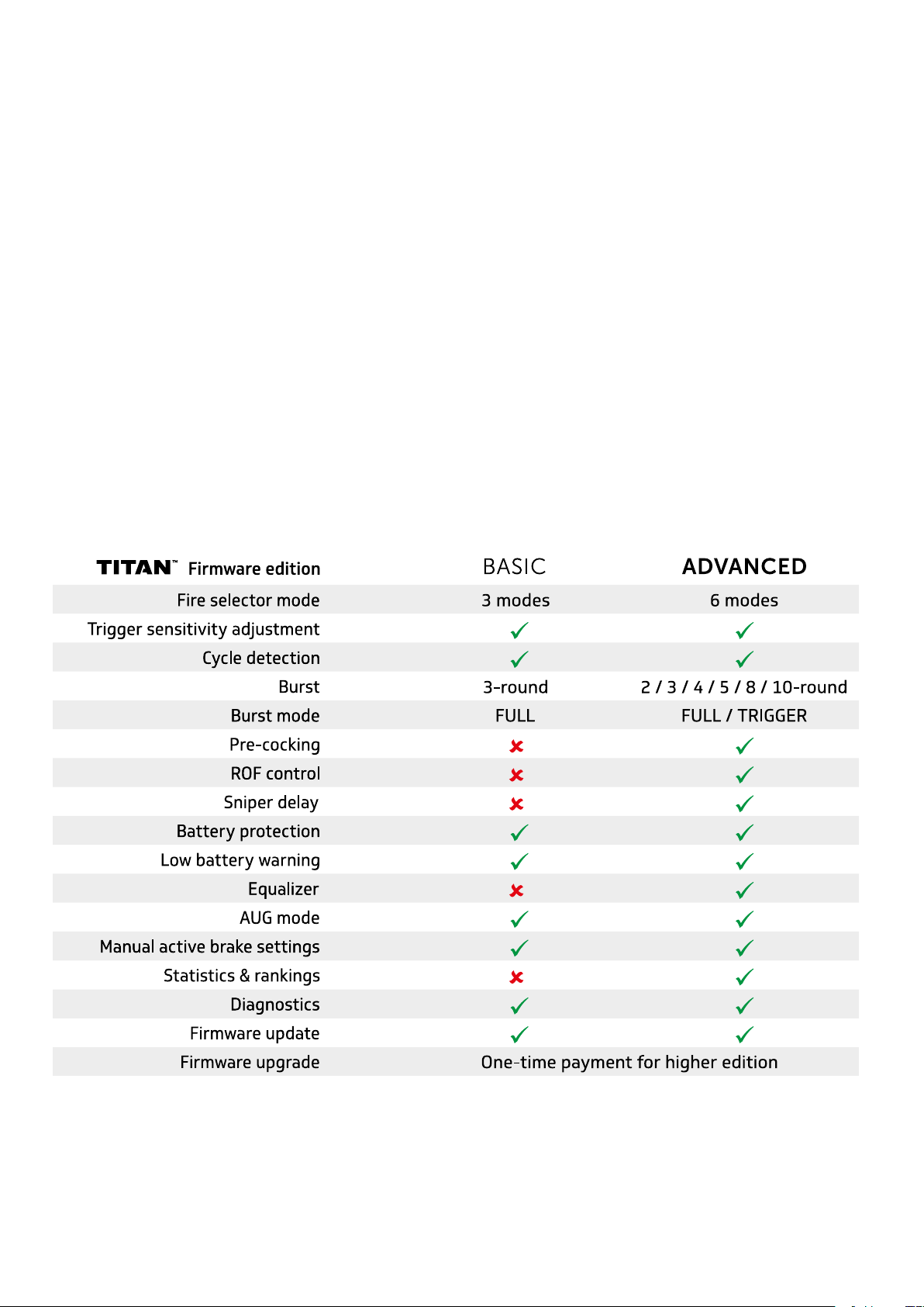
3. Firmware editions
The TITAN is currently available in two rmware editions: BASIC and ADVANCED. In the future,
the EXPERT edition will be also available. Thanks to the rmware editions, you do not need to
replace a drop-in unit - which is inside your AEG - to get more functions. Also, you do not have
to pay for functions that you do not need.
BASIC
The best for those who prefer simplicity
but require highest quality. Economic
version with limited number of functions.
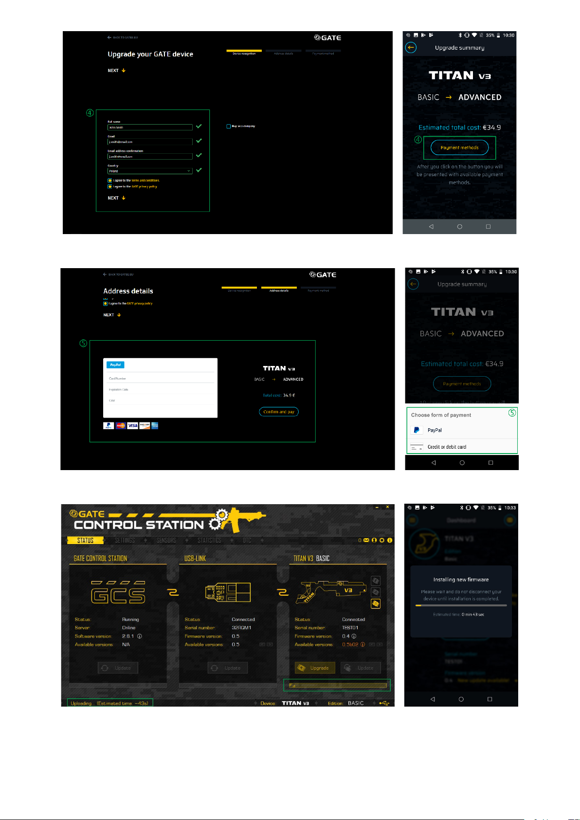
In order to upgrade your TITAN rmware from BASIC to ADVANCED, you need to purchase the
upgrade. Follow the steps on the website: www.gatee.eu/editions or use GCS App for Android
devices. The upgrade will be available for installation immediately aer payment.
ADVANCED
The best for those who like complex
solutions. Advanced version with wide
variety of functions. It enables access to
the Statistics and TITAN World Rankings.
9

101112


4. TITAN Kits
At this moment, TITAN is available for three dierent types of gearboxes. There is:
• TITAN V2 which is compatible with most V2 gearboxes
• TITAN V3 which is compatible with most V3 gearboxes
• TITAN V2 NGRS which is compatible with Tokyo Marui V2 NGRS gearboxes
Furthermore, TITAN V2 and TITAN V2 NGRS are divided in two types. Depending on where you
keep the battery, you can choose between FRONT and REAR wiring.
TITAN V3 has one universal type of wiring. If you have battery in buttstock, you can use
additional buttstock extension.
All the TITANs are available in two sets: Advanced Set and Basic Module.
Case 1
1. Do you have USB-Link? NO.
2. Do you prefer ADVANCED rmware or BASIC rmware edition? ADVANCED.
3. You should buy TITAN Advanced Set.
Case 2
1. Do you have USB-Link? YES.
2. Do you prefer ADVANCED rmware or BASIC rmware edition? ADVANCED.
3. You should buy TITAN Basic Module and Advanced Firmware Upgrade.
13

Case 3
Case 4
1. Do you have USB-Link? NO.
2. Do you prefer ADVANCED rmware or BASIC rmware edition? BASIC.
3. You should buy TITAN Basic Module and USB-Link separately.
1. Do you have USB-Link? YES.
2. Do you prefer ADVANCED rmware or BASIC rmware edition? BASIC.
3. You should buy TITAN Basic Module.
14

5. GATE Control Station (GCS)
GATE Control Station enables you to simply update the rmware and adjust the settings
using the USB-Link and the GATE Control Station™ app. Thanks to the GCS, you do not have
to remember complicated trigger sequences to program your unit. All the features are easily
accessible and simple to adjust with just one click.
Notice
At this moment, GCS can be used on PC/MAC and Android devices. iOS
will be supported aer release of GATE Bluetooth adapter.
We are constantly improving our applications. Each update brings new features and/or
corrections. All the changes are available in our changelog:
https://gatee.eu/technical-support/changelog
GCS allows you to:
• update or downgrade TITAN and USB-Link rmware
• upgrade TITAN rmware to ADVANCED or EXPERT edition
• change more than 20 TITAN settings
• calibrate trigger and re selector
• set trigger sensitivity
• check status of your TITAN sensors
• check statistics of your gun (rate of re, trigger response etc.)
• check diagnostic trouble codes (DTC)
• contact GATE Support Center (via error report, messenger or phone) [Android]
• receive in-app notications [Android]
5.1. Connecting TITAN to USB-Link and PC, MAC or Android Device.
Notice
You need the USB-Link and USB cable to connect TITAN with GATE Control Station.
Caution
Prevent the USB-Link and the ends of USB cable from contact with
conductive materials (e.g. dust, liquid, metal powder).
Notice
Do not remove the device cover.
15
1. Download and install GATE Control Station: www.gatee.eu/gcs
Notice
Your Android device must support OTG technology to run GATE Control Station app.
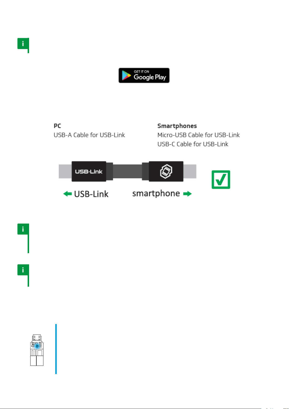
2. Connect the USB-Link to PC, MAC or smartphone using USB cable.
Notice
The dedicated GATE ‘Micro-USB Cable for USB-Link’ has the same connectors
on both sides. However, it is very important to which end of cable you
connect the USB-Link and smartphone. It will not work reversely.
Notice
If your USB-Link cannot be detected, please follow
instructions from GATE Control Station screen.
USB-Link has a 4-colour LED indicator.
BLUE (glowing)
The USB-Link is connected to a PC or smartphone. TITAN is not connected or a
PC driver is not installed. You can download the driver here:
www.gatee.eu/drivers
BLUE (blinking)
The USB-Link does not have an installed rmware. Please install the rmware.
16
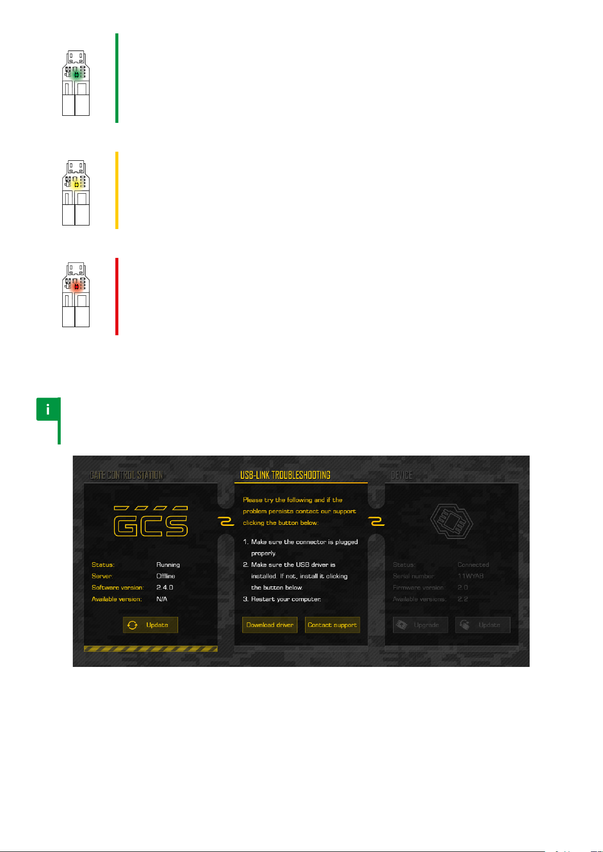
GREEN (glowing)
The USB-Link is connected to TITAN and PC, MAC or smartphone.
GREEN (blinking)
The USB-Link is connected to TITAN and PC, MAC or smartphone, but the
TITAN does not have an installed rmware. Please install the TITAN rmware.
YELLOW (glowing)
The USB-Link is transmitting data.
RED (glowing)
Communication with the TITAN was interrupted while saving settings. The
TITAN settings may be transmitted incorrectly. Please check the connection
between the USB-Link and the TITAN.
3. Connect TITAN to USB-Link.
Notice
If your USB-Link cannot detect TITAN, please check if there is
the same issue with another PC, MAC or smartphone.
If the problem still occurs, please contact our Support Center. You can:
a) email us at titan@gatee.eu
b) contact us via Facebook: www.facebook.com/gatee
c) call (+48) 122-100-523
17
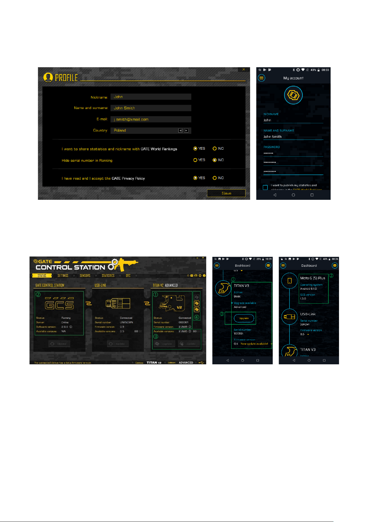
4. Now you can control TITAN via GATE Control Station.
During the rst start you will be asked to create your own prole. It is not obligatory but it will
help when you will be contacting our support.
5.2. Status tab
The status TAB informs you about version, edition, type and serial number of the
connected device, as well as application version and server status. Here you can simply
update or „downgrade your device or upgrade rmware of your unit to ADVANCED or EXPERT
edition.
18

There are four icons in the upper right corner:
Mail - includes messages and newsletter
Prole - allows you to change your privacy settings
Options - here you can choose the language (future function), switch update inverval, turn
on/o the autosaving and sounds
Info - basic legal information
5.3. Settings tab
Settings tab was created in order to simplify the conguration of your TITAN.
Factory reset – (also called “Hard reset”) restores all default settings, resets your statistics
and clears adaptation data.
Default setting – restores only default settings.
19

Settings tab:
Fire selector mode – allows you to choose how your replica will behave on each re selector
position:
• SAFE – replica will not re aer trigger pull
• SEMI – one pull of the trigger will result in only one shot
• BURST – one pull of the trigger enables you to shoot a pre-determined
number of BBs, which is very useful in MILSLIM and when using low-caps
• AUTO – pulling the trigger causes uninterrupted* series
of shots until the trigger is released
*series can be limited by Round Limit
Pre-cocking mode – allows for initial spring compression, which speeds up the trigger
response signicantly:
• AUTO MODE – the spring is automatically compressed aer each shot
• TRIGGER MODE – slow trigger action compresses the
spring, and fast trigger action res the shot
Please note: using PRE-COCKING increases wear and tear on the gearbox.
Pre-cocking boost – determines the strength of spring compression. The highest setting
results in the best trigger response, but also mostly increases wear and tear on the gearbox.
If you are facing overspin issue, set GEAR RATIO to HIGH SPEED.
Burst mode:
• FULL – every, even the shortest trigger action res the pre-determined number of
rounds
• TRIGGER – releasing the trigger while ring stops the burst sequence.
Burst – allows you to set how many BBs will be red
ROF stabilization:
• ON – ROF Control uses PWM (Pulse Width Modulation) to decrease ROF. Thanks to this,
gearbox works smoothly what decreases wear and tear of AEG internal parts. The
percentage value determines the PWM duty cycle and it does not reect ROF decrease.
• OFF – ROF Control adds breaks between shots to decrease ROF. It gives you more
realistic experience. This option set to 50% will signicantly reduce the rate of re.
ROF control – enables a reduction in a gun’s rate of re. You use stronger LiPo batteries, and
still have a ROF just like in a real gun.
Sniper delay – lets you to set delay between each SEMI shots to simulate the delay from reload
or recoil. You can set 0.5s, 1s, 2s or 3s delay. By choosing ‘VIB’ option, you can enable vibration
which will inform you when the gun is ready to re again.
20

Battery protection – modern LiPo and LiFe batteries are very sensitive to over-discharge. The
microprocessor monitors the battery voltage constantly. When the voltage drops down to a
critical level, it will not allow ring.
Battery cell – when the battery voltage drops to the specied level (in relation to one cell), the
motor will vibrate. You can set: OFF, 3.2V or 3.4V per cell for LiPo battery and 2.7V or 2.9V per
cell for LiFe battery.
30-Round Limit – an AEG can continuously re max. 30 BBs. To re more BBs, you must release
the trigger before. This is protection against trigger jam. Important: in case of emergency, you
can also stop ring by switching the re selector position.
Cycle detection – allows to switch OFF or ON the optical gear sensor. Cycle detection OFF can
be compared with the “emergency mode” for troubles with gear sensor. Most of TITAN features
will be disabled, but you can still shoot on ‘AUTO’.
Thanks to the gear sensor, TITAN precisely detects in which position the cycle should nish.
Therefore, even the shortest trigger action produces at least one full cycle.
Equalizer (dynamic trigger point):
• OFF - to re the next shot, you need to release the trigger
until it reaches the selected trigger sensitivity level
• 2LVL - to re the next shot, it is enough to release the trigger so as it
changes the state of two trigger sensors or ~40% of trigger movement
• 1LVL - to re the next shot, it is enough to release the trigger so as it
changes the state of one trigger sensor or ~20% of trigger movement
1LVL or 2LVL are especially useful when the trigger sensitivity level is very high. Then you do
not need to fully release the trigger while quickly ring on SEMI.
Active brake - it automatically adjusts the motor’s braking power according to your needs.
This prolongs the lifespan of the motor and reduces the heat. Now you can also choose your
own value depending on your needs.
Gear ratio - to make the PRE-COCKING work with the highest level of precision you should
dene the gears type in your AEG. Available types: STANDARD, HIGH TORQUE, HIGH SPEED,
DSG, 19-TOOTH.
Typical gear ratio settings (excluding DSG and 19-tooth):
• HIGH TORQUE: <15 RPS
• STANDARD: 15-25 RPS
• HIGH SPEED: >25 RPS
If overspin issue occurs, you should switch the gear type to the next level (e.g. STANDARD to
HIGH TORQUE).
21
Notice
Regional lock designed for German players will disable all the burst and auto options.
Notice
The DSG and 19-TOOTH gear ratio options are not available for TITAN V2 NGRS.
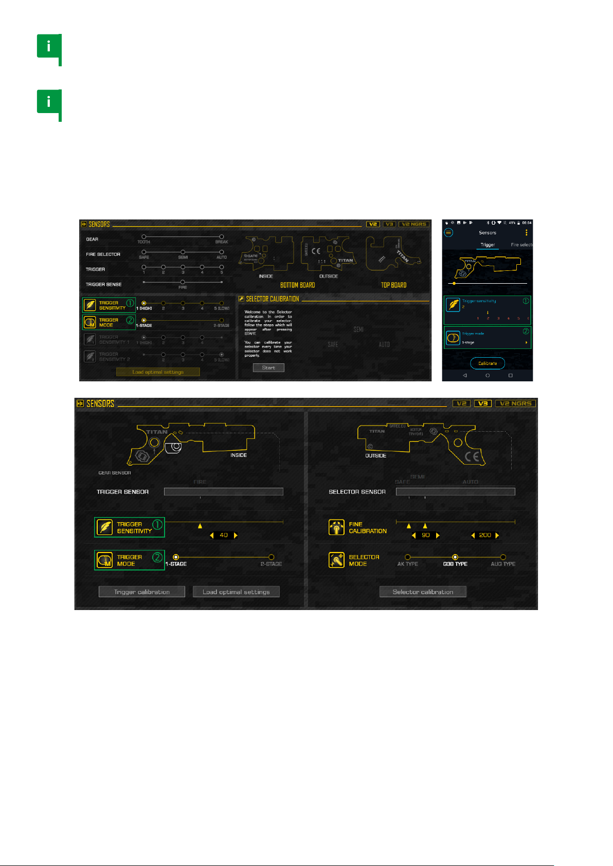
5.4. Sensors tab
Depending on your TITAN model, you will see one of the three screens below.
22

We designed the Sensors TAB in order to let you choose the trigger sensitivity or trigger
mode that is the best for you. Thanks to live view, you do not need to mechanically adjust your
trigger. Simply choose the value and check if it suits you.
You will be warned if the trigger sensitivity value reaches extremely low level.
23

5.5. Statistics tab
The statistics tab contains main information about your replica performance. You can simply
clear each value by clicking “Reset” button. You can also independently reset BB1 and BB2
counter.
TITAN gives you the option to check:
• Rate of re - Minimum, Average, Maximum
• Trigger response - Minimum, Average, Maximum
• Module’s temperature - Minimum, At this moment, Maximum
• Motor current - Average AUTO, Average SEMI, Maximum Peak
• Battery voltage - Minimum, Last, Maximum
• Number of red BBs - BB1, BB2, TOTAL
Notice
Statistics are saved every ten seconds. If you want to save your
statistics immediately, switch the re selector to SAFE.
24
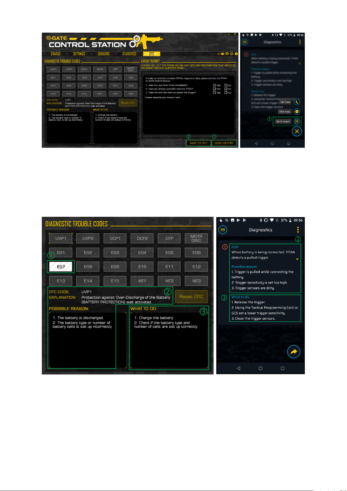
5.6. Diagnostic Trouble Codes (DTC) tab
This TAB will help you to troubleshoot your replica in case of any issue. If you need additional
help, you can contact our Support Center using “SEND REPORT” button, or save the report
using “SAVE TO FILE” button.
If an error occurs, it will be highlighted and described. In such a case, we suggest to
follow ”WHAT TO DO” instructions in the rst place.
25

6. TITAN V2
TITAN V2™ is an AEG Control System for V2 gearboxes which will transform your AEG into an
advanced training weapon. Adjust your AEG and check the Statistics using USB-Link and GATE
Control Station app for PC/MAC and Android devices. Gain a tactical advantage thanks to the
extremely fast trigger response, option of adjusting trigger sensitivity to your preferences and
many other useful functions. Give your AEG a new lease of life!
Thanks to the optical sensors we have eliminated the problem of faulty switches that can
occur in competitors’ drop-in mosfets. The trigger has no mechanical connections with the
PCB. This eliminates mechanical stresses and provides for high reliability.
TITAN V2 has the following sensors:
• 1 sector gear sensor
• 2 re selector sensors
• 5 trigger sensors
26
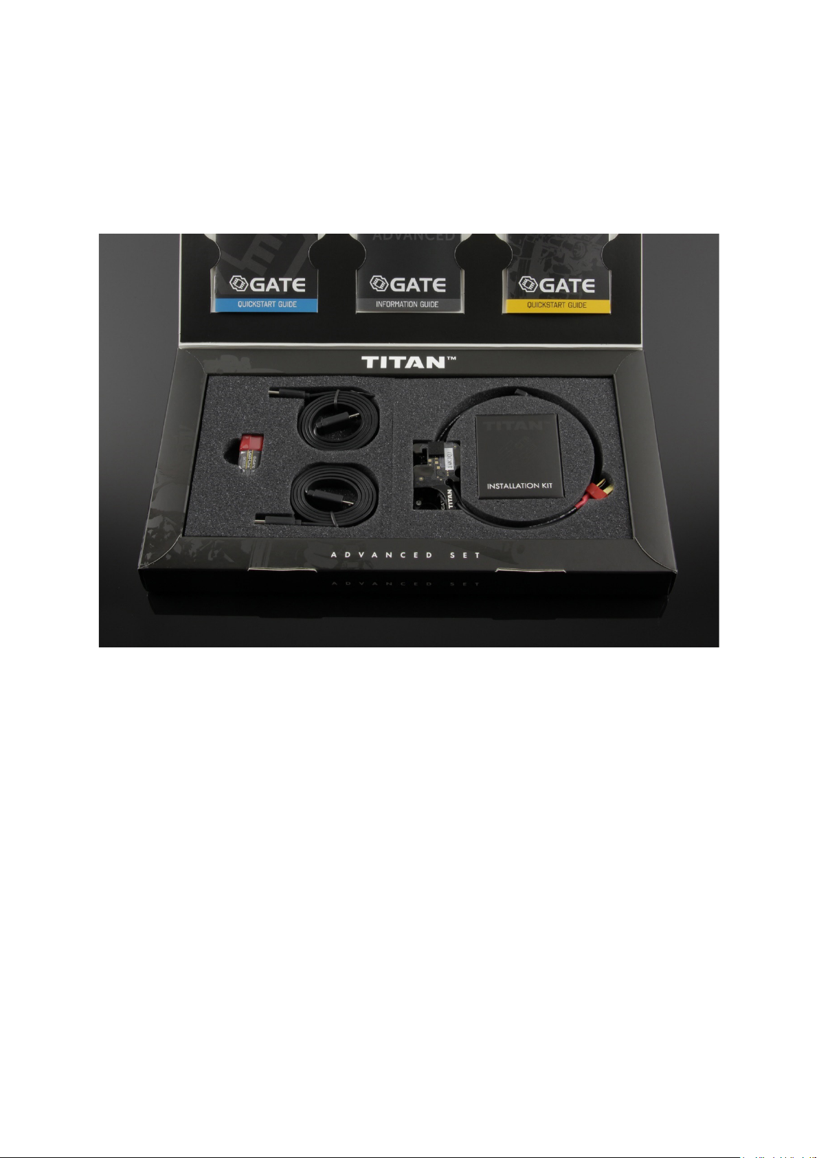
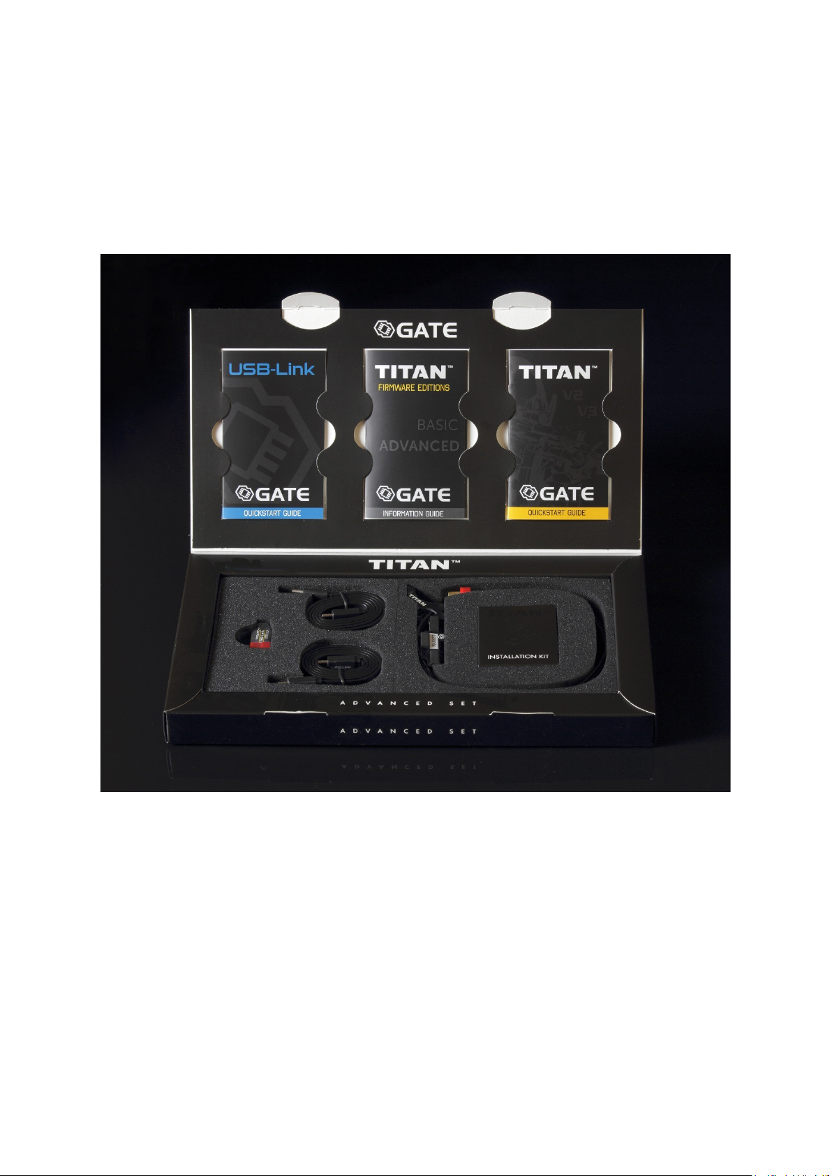
6.1. TITAN V2 Advanced Set
At once you purchase TITAN with ADVANCED rmware edition, USB-Link and USB cables
allowing to connect TITAN to PC/MAC as well as Android device.
The ADVANCED rmware edition oers wide variety of functions and is dedicated for those
who like complex solutions. It enables access to the Statistics and TITAN World Rankings. To
learn all the dierences between rmware editions, please check the comparison table.
Advanced Set contents:
1. TITAN V2 with ADVANCED rmware edition (rear or front wired)
2. USB-Link for GATE Control Station™ App
3. USB-A Cable for USB-Link [1.5m / 4 11in]
4. USB-C Cable for USB-Link [0.6m / 1 11in]
5. Micro-USB Cable for USB-Link [0.6m / 1 11in]
6. Installation Kit
7. Quickstart Guides
27

6.2. TITAN V2 Basic Module
The best if you long for having TITAN in two or more airso guns. Then you do not need the
second USB-Link from the Advanced or Complete set. It includes TITAN with BASIC rmware
edition.
The BASIC rmware edition is an economic version with limited number of functions, dedicated
for those who prefer simplicity but require highest quality. If you decide to have more
functions, there is always option to upgrade rmware from BASIC to ADVANCED.
Basic Module is also suitable for you if you decide to purchase the USB-Link separately.
Basic Module contents:
1. TITAN V2 with BASIC rmware edition (rear or front wired)
2. Installation Kit
3. Quickstart Guide
Notice
In order to congure TITAN, you need the USB-Link or Tactical
Programming Card which is not included in this kit.
28

6.3. Installation safety
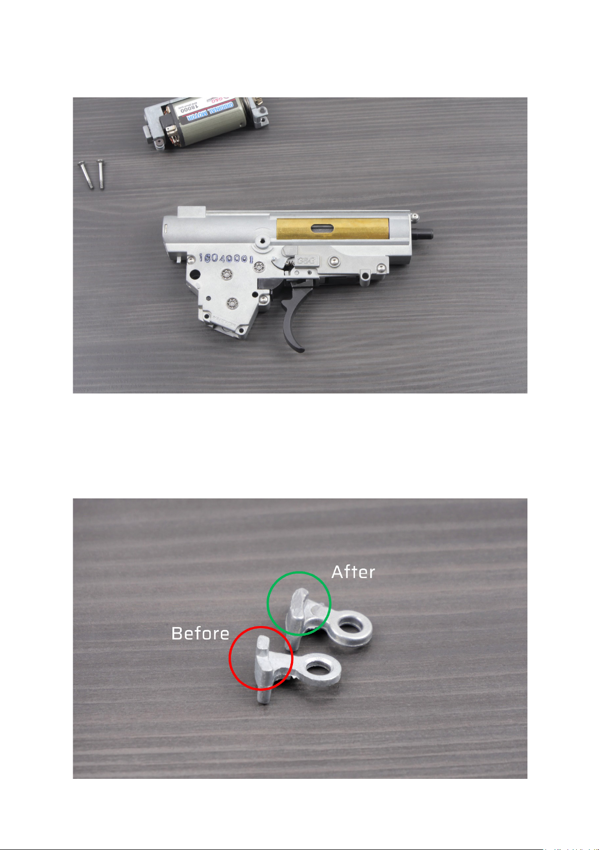
Caution
A sector gear can damage a gear sensor during installation.
Stay careful to avoid this damage.
Caution
Gearbox shell manufactured by ICS and Krytac must be modied to
achieve 100% compatibility with TITAN V2. Lack of the modication will
permanently damage your unit, which is not covered by the warranty.
29

30

Caution
Placing the washers in wrong order will cause short circuit and permanent
damage to the TITAN, which is not covered by the warranty.
31
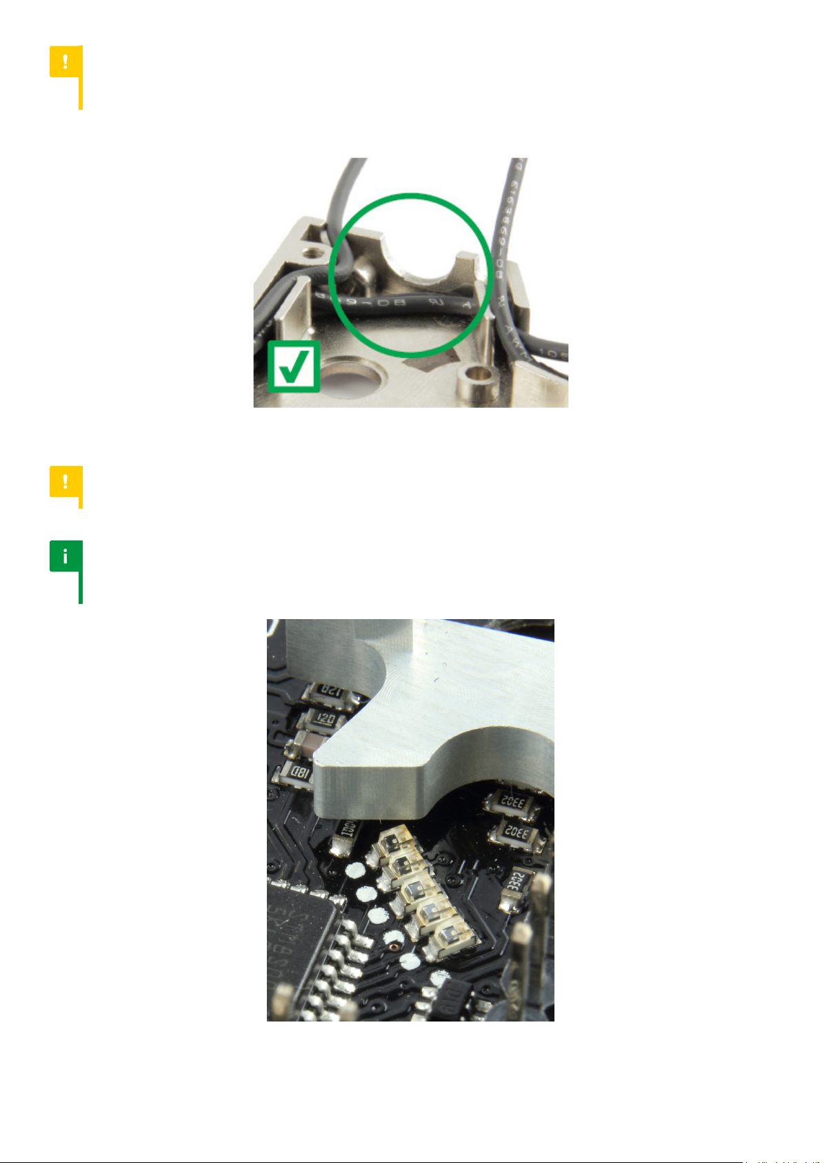
Caution
The improper placement of wiring under motor gear can
cause insulation damage and a short circuit.
Caution
Do not pull the trigger when gearbox is open. It may result in trigger sensors’ damage.
Notice
In case of some triggers (e.g. speed or CNC triggers), rst trigger
sensors might be covered even if the trigger is not pulled.
32
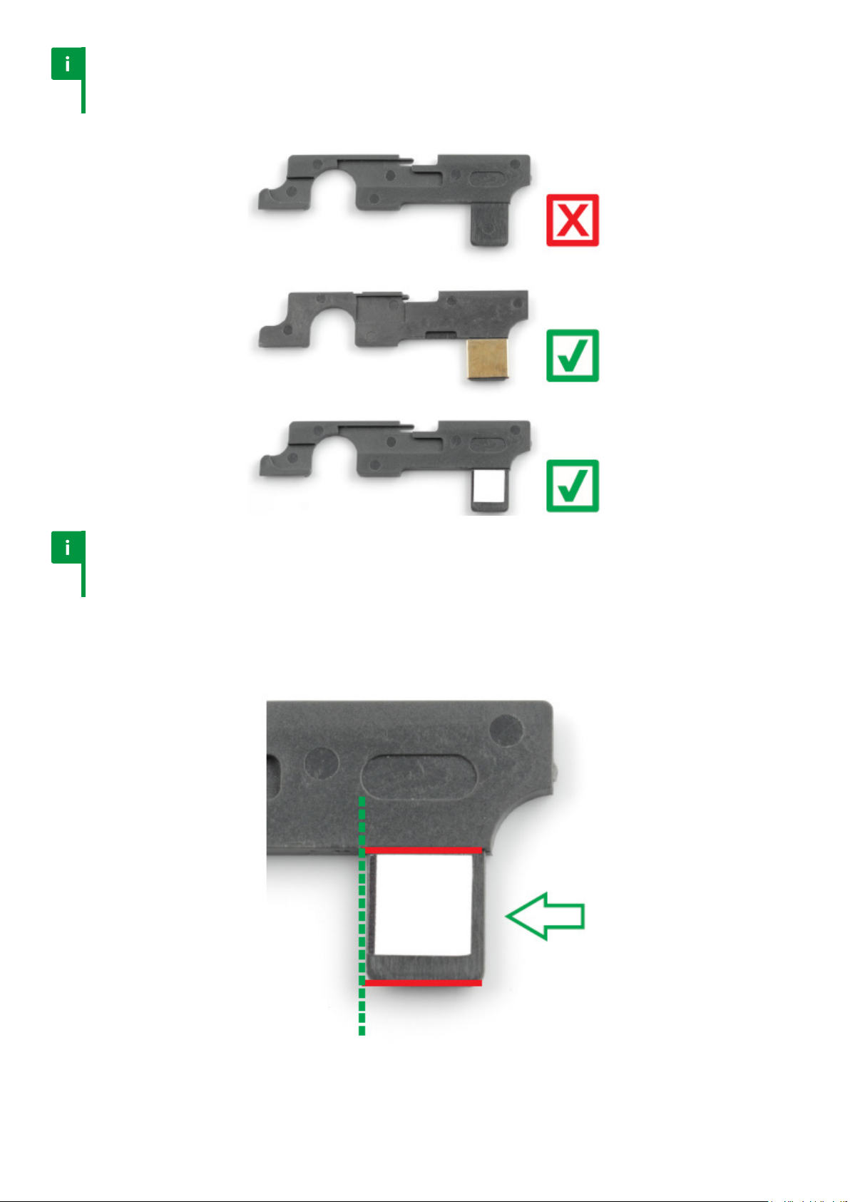
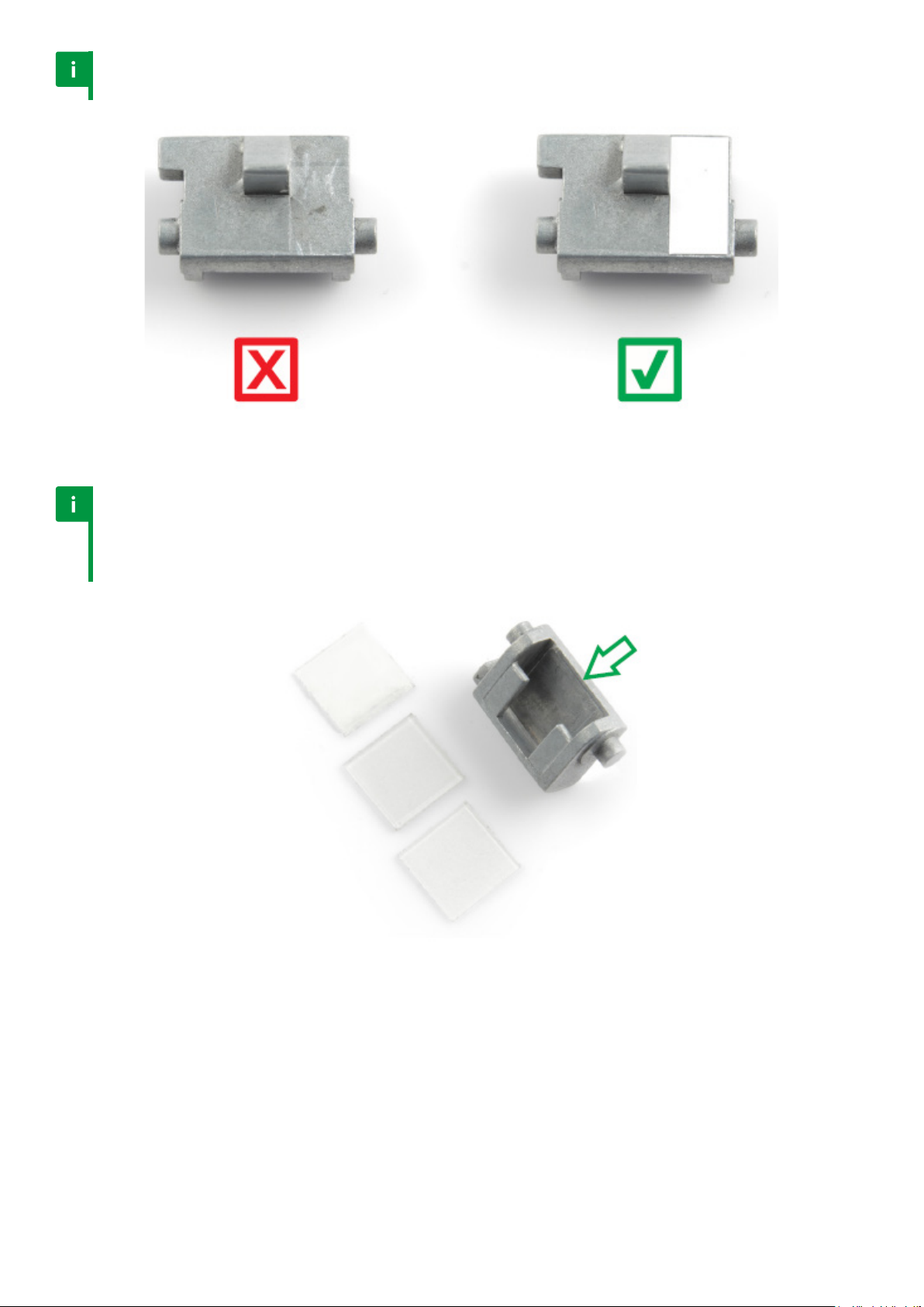
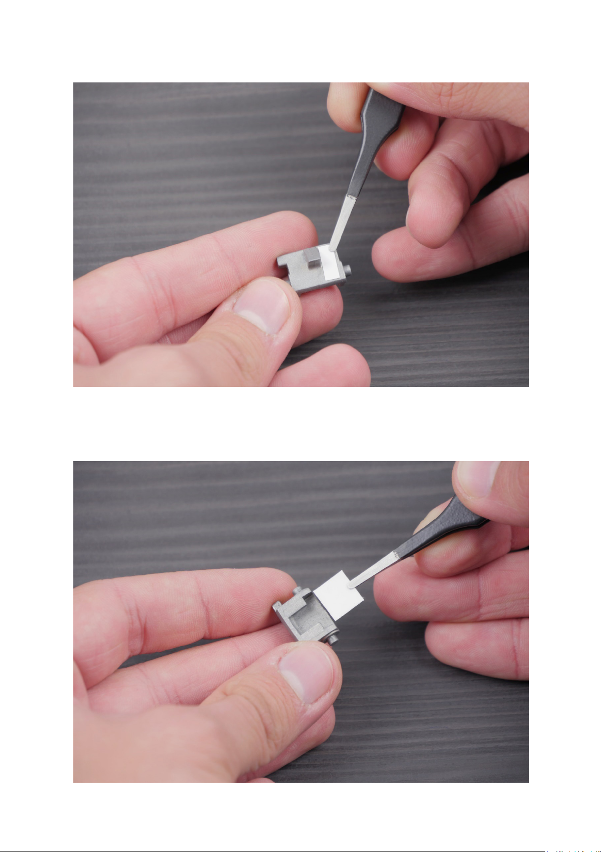
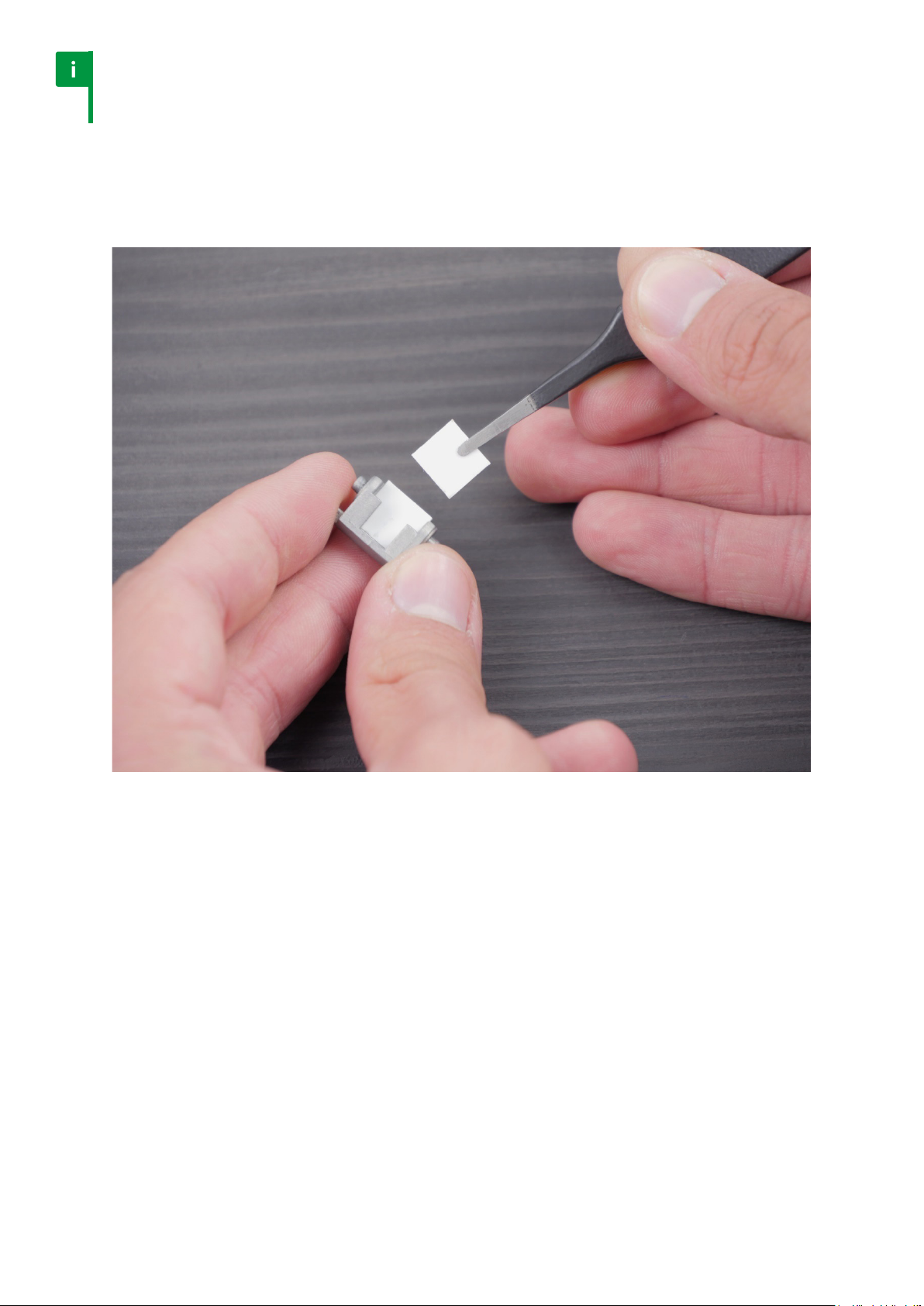
Notice
A selector sensor does not detect black surface. If your selector does
not have metal connector, you must use sticker from the kit.
Notice
The sticker position is very important. Pay attention to place the sticker
very close to the le edge, between the top and bottom red lines.
The set contains 3 dierent sticker types. At rst, use the sticker with narrower black line. If
you are not able to calibrate selector well, you should try other stickers.
33
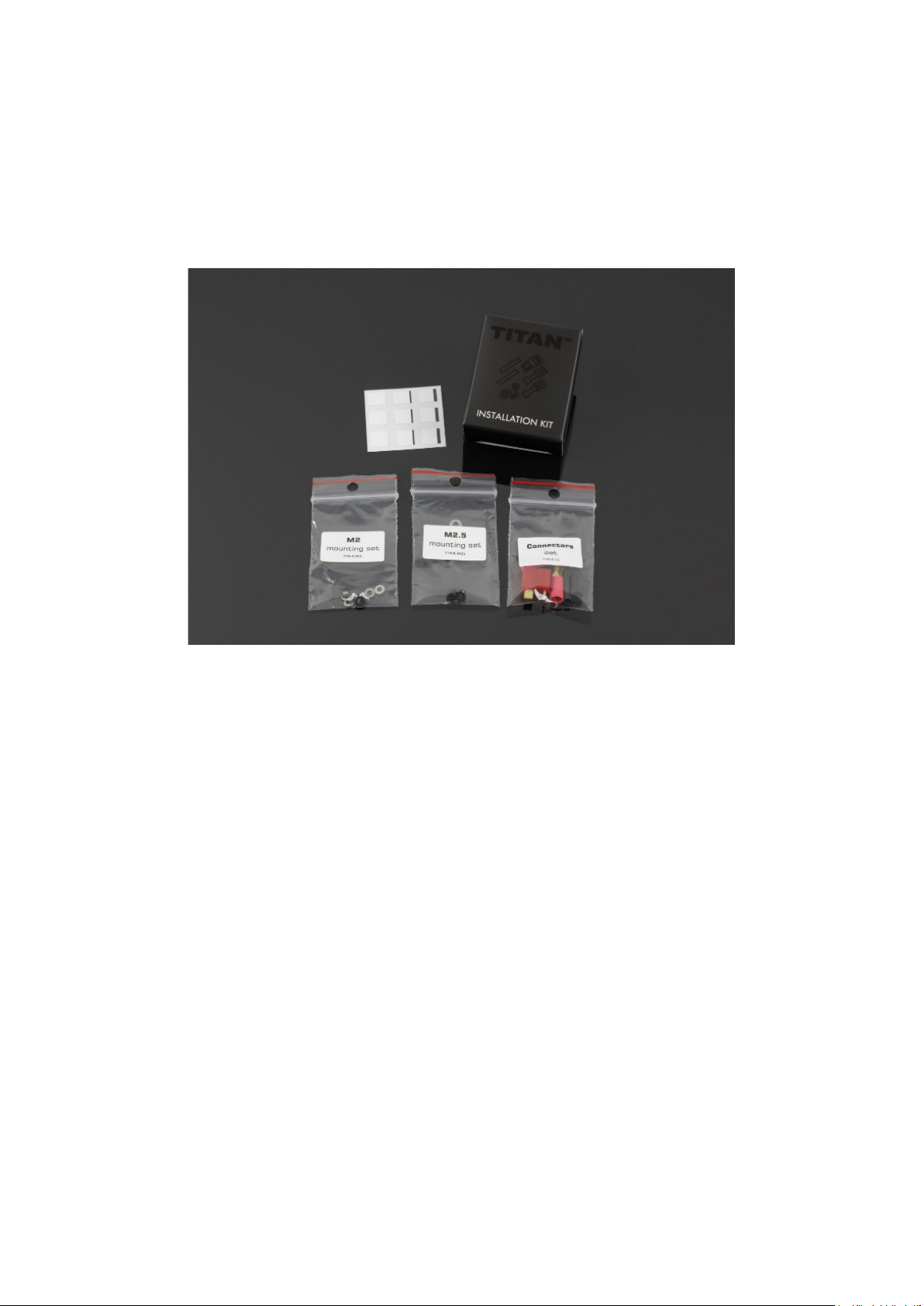
6.4. Installation
Installation Kit contents:
1. Selector plate stickers
2. Female deans-t connector
3. Motor connectors 2.8 x 0.5 mm [0.11 x 0.02 in]
4. 0.7mm [0.03 in] screw and washers set
5. 0.5mm [0.02 in] screw and washers set
You will need:
• cross-head screwdriver
• at-blade screwdriver
• metal le or milling machine
• solvent
• grease
• USB-Link, micro USB-Cable and PC / MAC or OTG cable and Android device
Follow the steps below in order to mount the TITAN drop-in module:
1. Remove the gearbox from the AEG body.
2. Disassemble your gearbox, take out all the internals.
3. Clean the gearbox case using solvent.
34
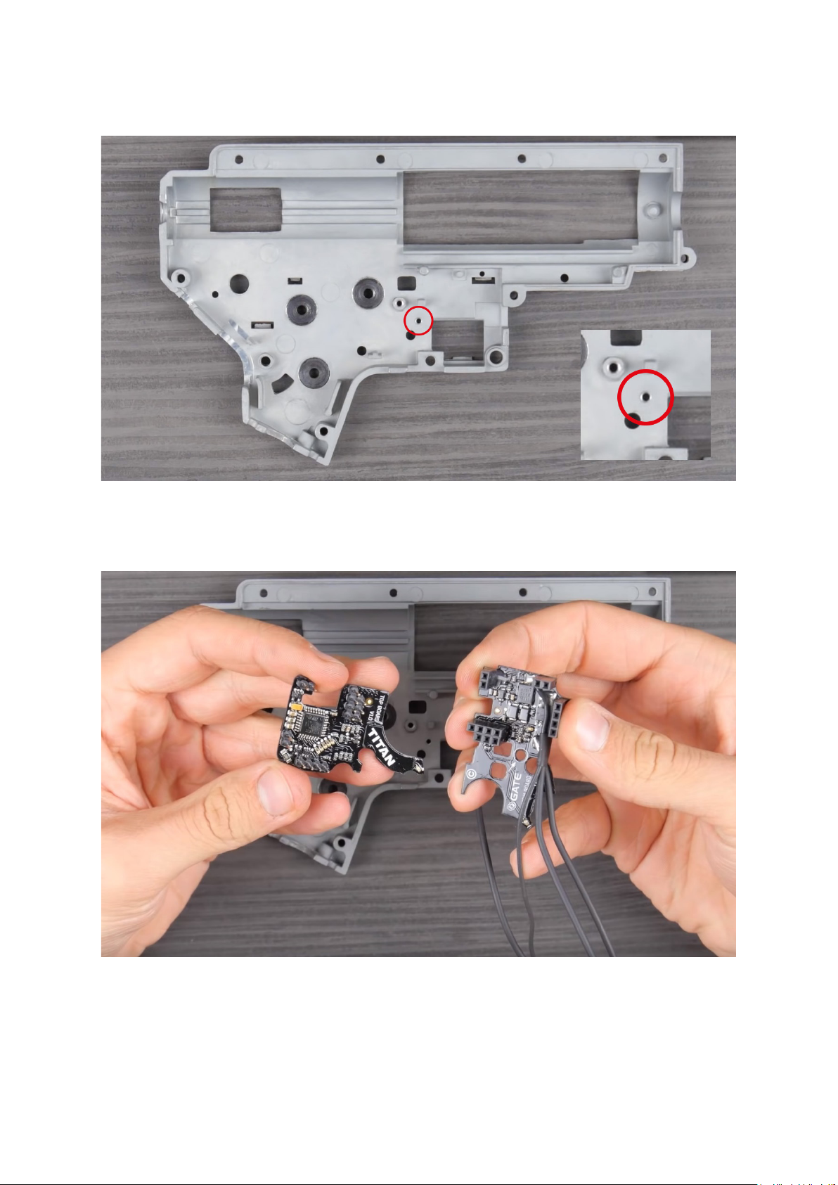
4. Pay attention to the marked area. If you see that it is not smooth, use a
metal le or grindstone to prepare the surface. The gearbox surface should
be smooth, with no sharp edges which would damage the TITAN.
5. Detach the drop-in module carefully.
35

6. Place the bottom board on the bottom part of the gearbox. Do not use
a screw yet. Check if the bottom board is laid at in the gearbox.
7. Make sure the electronic components do not touch the gearbox case.
36

8. Use the insulation (black) washer from the kit. ATTENTION! The insulation washer must
protect the circuit board. The metal screw and metal washer cannot touch the board
directly. It can result in a short circuit and TITAN damage which is not covered by the
warranty.
9. Screw on the bottom board to the case. Use the original screw or the one from the
TITAN kit.
37

10. Check if the screw sticks out of the gearbox.
11. If so, add metal washer(s) included in the kit. Make sure that the metal washer is placed
between the screw and the insulation washer. It cannot touch the circuit board directly.
38
12. Check if the top board ts gearbox without any problems.
13. Loosen the screw. Adjust the position of the bottom board. The distance between
the board and the bearing should be similar as indicated in the marked area.
39
Notice
Sector gear sensor placement is very important.
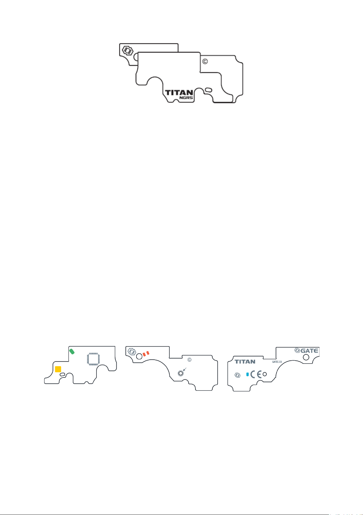
14. Make sure the marked areas are not covered by board or wires.
40
15. Check if sensors are clean and not covered by wires.
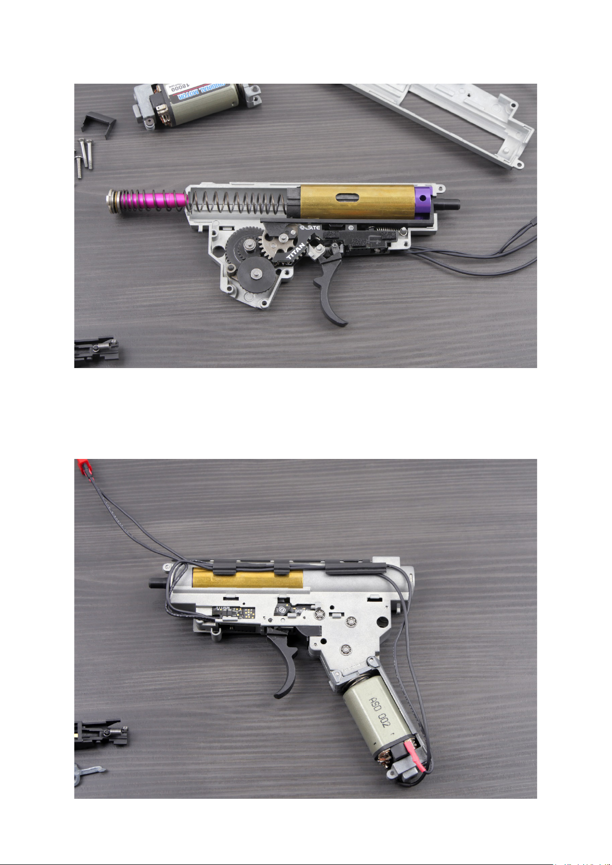
16. Some gearboxes need modication. Check if your gearbox
has the marked pins. If so, remove them.
41

17. Check if both parts of the gearbox t together perfectly.
18. Mount the trigger without spring. Insert the TITAN top board. Close
the gearbox. When the gearbox is closed, carefully check if the trigger
moves smoothly and does not touch any TITAN’s components.
42
19. Mount the sector gear, trigger with spring and top TITAN board.
Make sure that the gear does not touch TITAN.
20. Close the gearbox. Tighten two screws on the top part of the gearbox case.
43

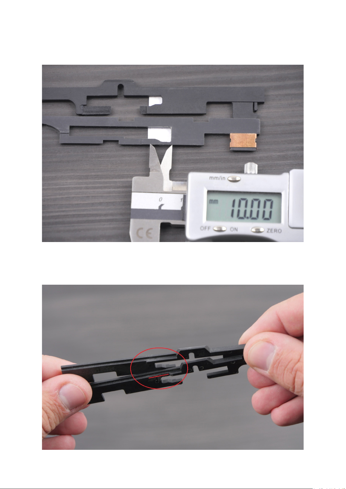
21. Prepare selector plate. If the selector plate does not have copper connector, you need
to modify it. The black surface does not reect light, so sensors cannot work properly.
22. In order to modify the black plate, use a sticker from the
installation kit. At rst, try to use the ‘middle’ sticker.
Notice
If the selector plate has copper connector, do not make any modications.
44

23. Black plate aer modication. The sticker location is very important.
It should be as close to the le side as possible.
24. Install the selector plate.
45

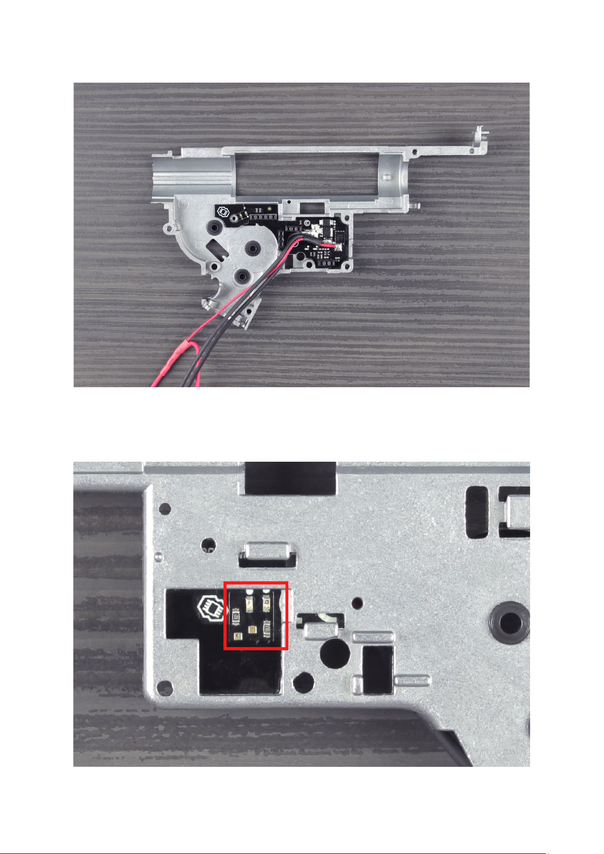
25. Connect TITAN to your PC using USB-Link. Start the GATE Control Station App.
26. Pull the trigger slowly. The TRIGGER SENSORS LED indicators will stop glowing,
one by one. They indicate active sensors. In case of some trigger models,
rst sensors might be active even when the trigger is not pulled.
46

47
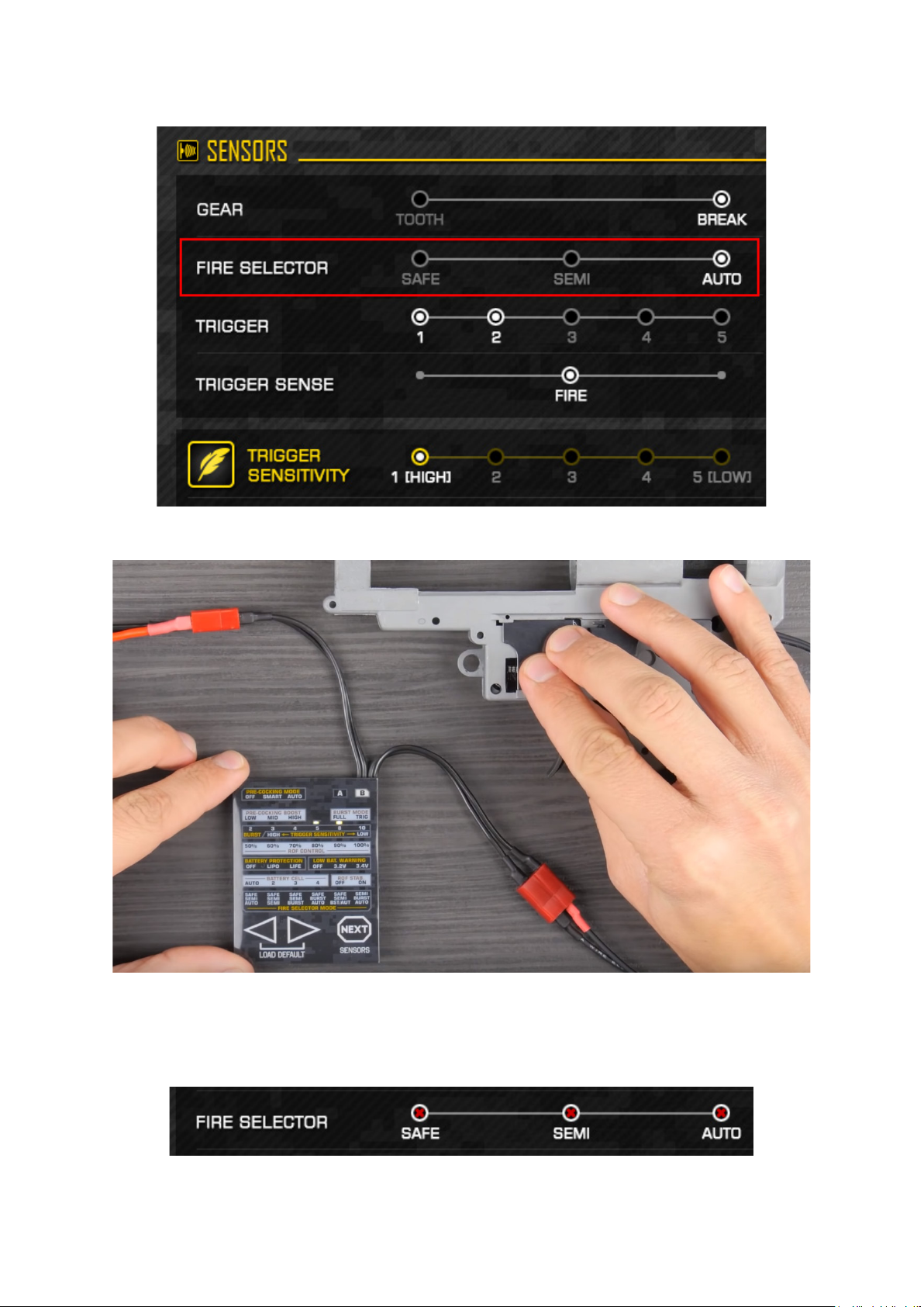
27. Check if the sensors recognize the selector plate. Moving the selector plate, verify if TITAN
detects SAFE, SEMI and AUTO.
28. If all the three LED indicators are ON, this means an error.
48

Notice
This error occurs mostly when a selector plate does not reect light. It can also
occur if too much light reaches sensors. Then you need to cover the sensors.
29. Turn the gear slowly to check if the sensor detects teeth. Keep in mind
that the TITAN reads the sensors much quicker than the GCS.
49
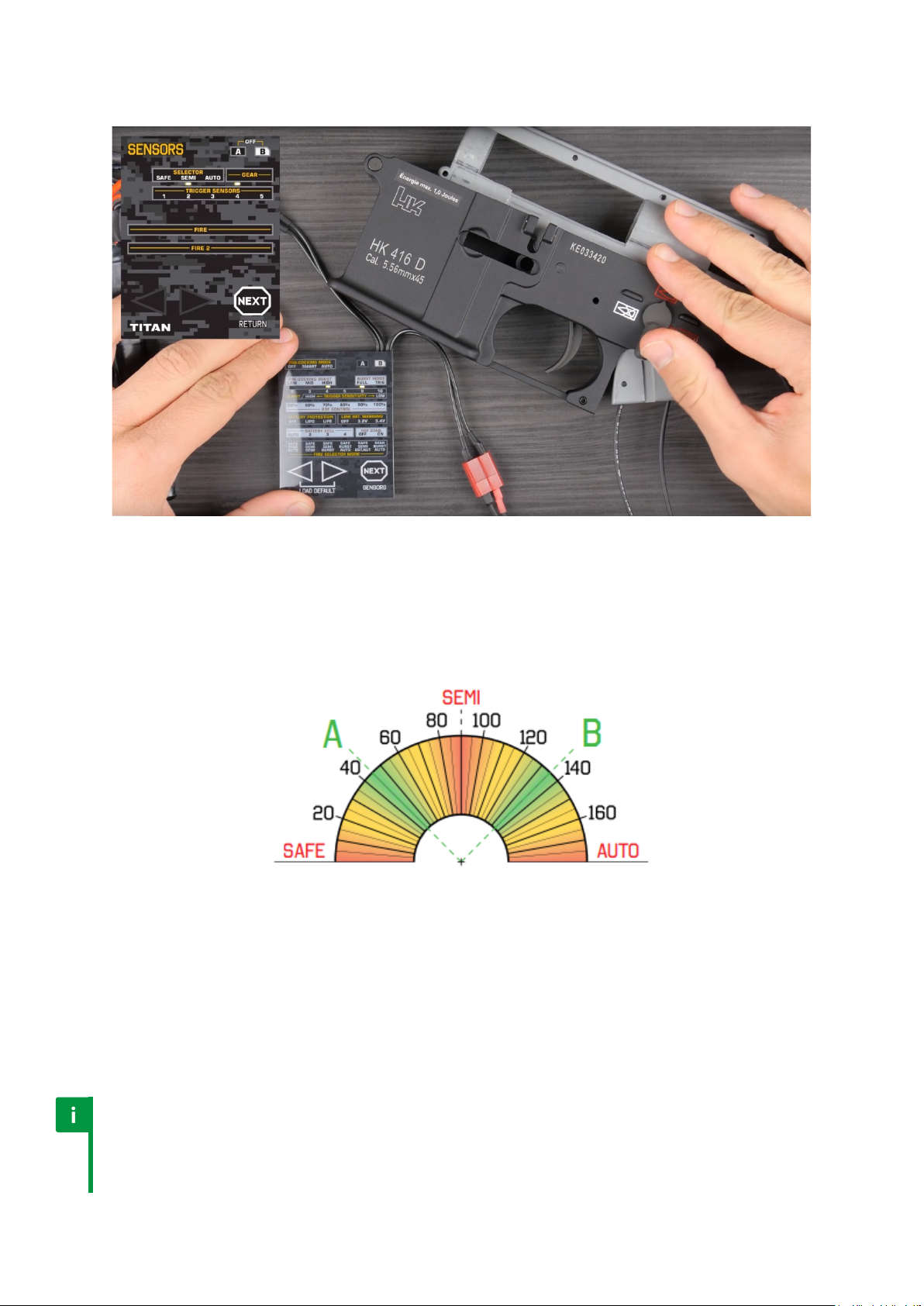
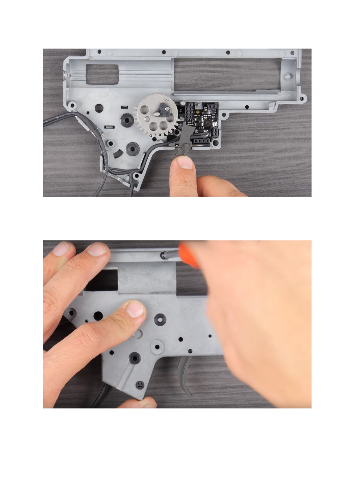
30. Insert gearbox into body and check whether the TITAN
detects the re selector position correctly.
Switch should take place approximately halfway between selector positions:
a) SAFE - SEMI ~45°
b) SEMI - AUTO ~135°
Otherwise, you need to modify the selector plate with other sticker.
31. If all the sensors work awlessy, you can assemble the gearbox. Do not use too much
grease. In a critical situation, excessive grease may cover a sensor.
Notice
A few initial shots are ‘calibration shots’. TITAN adapts to the gearbox
conguration. In order to readapt TITAN, you must restore factory settings
or change gear ratio. This is necessary e. g. if you replaced motor
50

7. TITAN V3
TITAN V3™ is an AEG Control System for V3 gearboxes which will transform your airso gun
into an advanced training weapon. Adjust your AEG and check the Statistics using USB-Link
and GATE Control Station app for PC/MAC and Android devices. TITAN V3 enables you to adjust
the trigger sensitivity with military precision. The innovative proximity trigger sensor oers
you even 250 possible sensitivity settings. Gain a tactical advantage thanks to the extremely
fast trigger response and many other useful functions. Give your AEG a new lease of life!
TITAN V3 has the following optical sensors:
• 1 sector gear sensor
• 1 re selector sensor
• 1 proximity trigger sensor
51
7.1. TITAN Advanced Set
At once you purchase all you need to take total advantage from TITAN. It includes TITAN with
ADVANCED rmware edition.
The ADVANCED rmware edition oers wide variety of functions and is dedicated for those
who like complex solutions. It enables access to the Statistics and TITAN World Rankings. To
learn all the dierences between rmware editions, please check the comparison table.
Advanced Set contents:
1. TITAN V3 with ADVANCED rmware edition
2. USB-Link for GATE Control Station™ App
3. USB-A Cable for USB-Link [1.5m / 4 11in]
4. USB-C Cable for USB-Link [0.6m / 1 11in]
5. Micro-USB Cable for USB-Link [0.6m / 1 11in]
6. Installation Kit
7. Quickstart Guides
52

7.2. TITAN Basic Module
The best if you long for having TITAN in two or more airso guns. Then you do not need the
second USB-Link from the Advanced set. It includes TITAN with BASIC rmware edition.
The BASIC rmware edition is an economic version with limited number of functions, dedicated
for those who prefer simplicity but require highest quality. If you decide to have more
functions, there is always option to upgrade rmware from BASIC to ADVANCED.
Basic Module is also suitable for you if you decide to purchase the USB-Link separately.
53

Basic Module contents:
1. TITAN V3 with BASIC rmware edition
2. Installation Kit
3. Quickstart Guide
Caution
TITAN V3 is compatible with most standard V3 gearboxes. Please note that
ARES and UMAREX gearbox shells as well as Tokyo Marui Next Generation
gearboxes are not compatible with TITAN V3. If you are not sure whether
your gearbox is compatible, please contact us at titan@gatee.eu
Notice
TITAN V3 is not compatible with Tactical Programming Card.
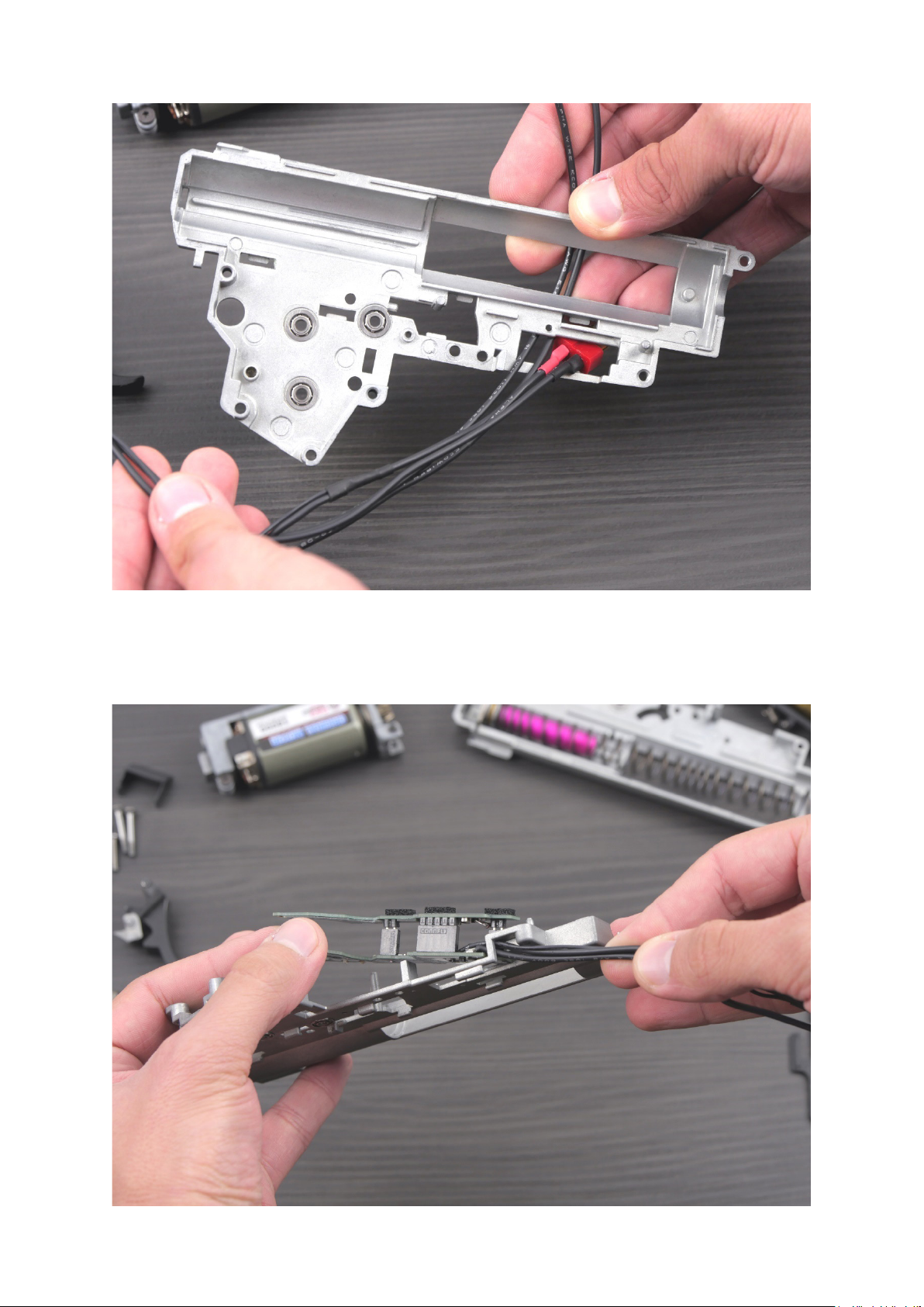
7.3. Installation safety
Notice
The TITAN V3 ts CNC gearboxes with very small backlash. While tting the
TITAN, pull the cables and at the same time push the board into the right place.
Pay attention to the area marked in yellow to t the board correctly.
54
Notice
Use the trigger sticker to make it visible for trigger sensor.
Notice
TITAN detects trigger position very precisely. In order to use it, you need to
eliminate trigger backlash. The set contains 3 trigger anti-backlash stickers
of dierent thickness. Try each of them and choose the most proper one.
55

Notice
The selector plate requires modication. Place the selector
sticker according to the photos below.
Notice
The sticker position is very important.
7.4. Installation
Installation kit contents:
1. Selector plate stickers (3 pcs)
2. Trigger stickers (6 pcs)
3. Connectors set
4. 0.15mm [0.006 in] trigger anti-backlash stickers (3 pcs)
5. 0.3mm [0.012 in] trigger anti-backlash stickers (3 pcs)
6. 0.5mm [0.02 in] trigger anti-backlash stickers (3 pcs)
7. 0.3mm [0.012 in] washers set
8. 0.2mm [0.008 in] washers set
9. 0.1mm [0.004 in] washers set
56

You will need:
• cross-head screwdriver
• at-blade screwdriver
• metal le or milling machine
• solvent
• grease
• USB-Link, micro USB-Cable and PC / MAC or OTG cable and Android device
Follow the steps below in order to mount the TITAN drop-in module:
1. Remove the gearbox from the AEG body.
2. Disassemble your gearbox, take out all the internals.
57

3. Clean the gearbox case using solvent.
4. Detach the drop-in module carefully.
58
5. Route the wires through gearbox shell from the inside.
6. Place the wires in gearbox shell so as the unit can t properly without any resistance.
59

7. Place the bottom board on the bottom part of the gearbox. Do not use
a screw yet. Check if the bottom board is laid at in the gearbox.
8. Make sure the electronic components do not touch the gearbox case.
60

9. If the bottom board ts correctly, use a cut-o lever screw to
stabilize the unit. Use also the included washers.
Notice
TITAN V3 does not require an insulation washer.
10. Check if the screw sticks out of the gearbox.
61
11. If so, add metal washer(s) included in the kit.
12. Check if the top board ts gearbox without any problems.
62

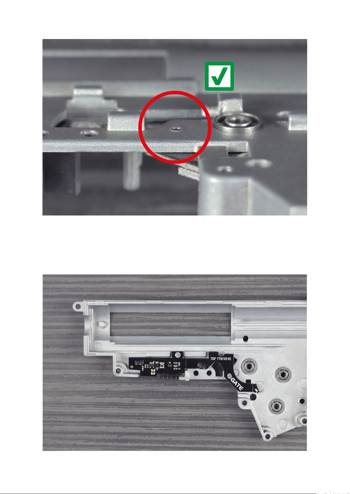
13. Loosen the screw. Adjust the position of the bottom board. The distance between
the board and the bearing should be similar as indicated in the marked area.
Notice
Sector gear sensor placement is very important.
63
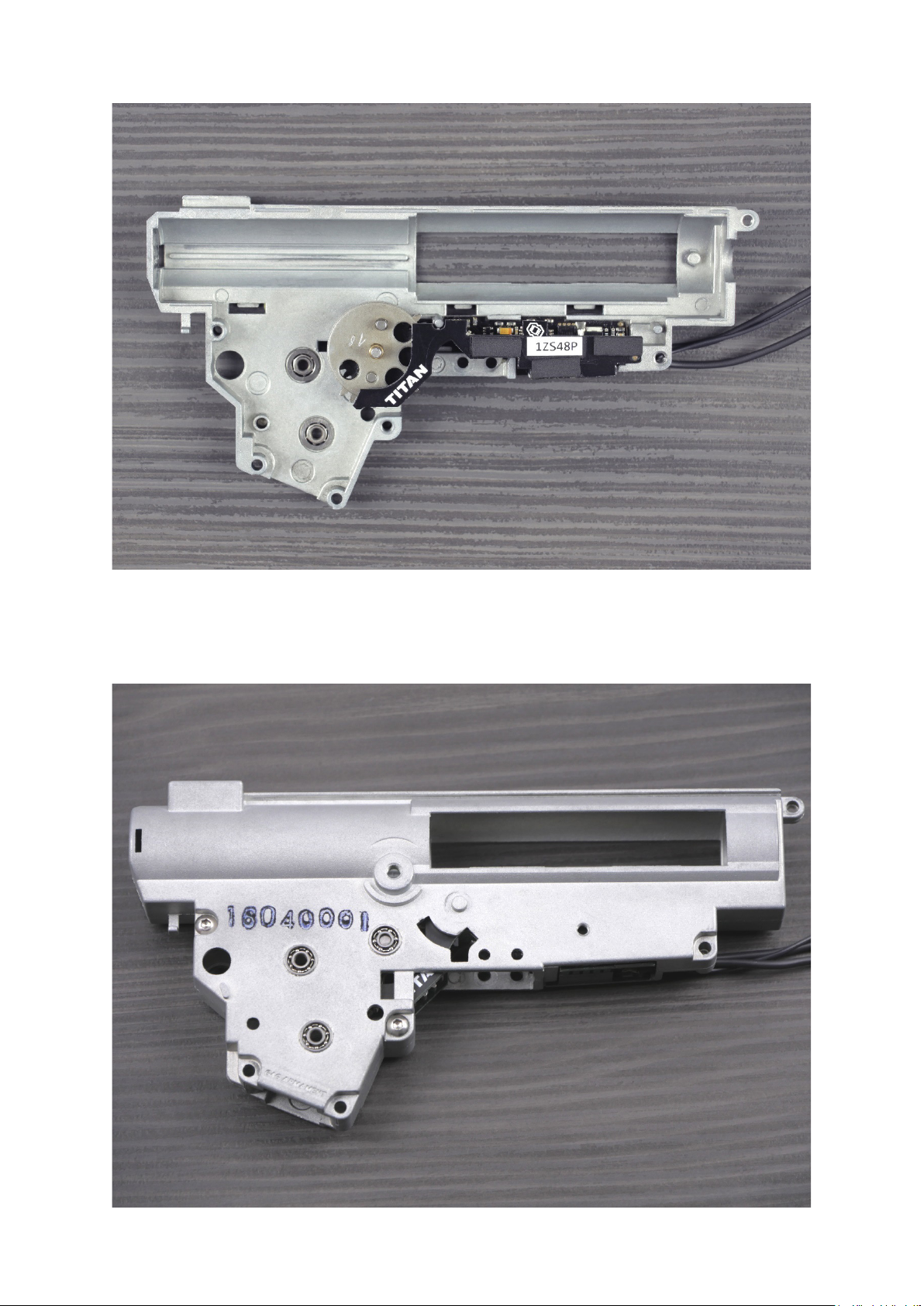
14. Mount the sector gear and top TITAN board. Make sure that the gear does not touch TITAN.
15. Close the gearbox. Use at least two screws.
64

16. Connect TITAN to your PC through USB-Link. Start the GATE Control Station App.
17. Turn the gear slowly to check if the sensor detects teeth. Keep in mind that the TITAN
reads the sensors much quicker than the GCS.
65
18. Use solvent to clean trigger elements. Next, paste the smaller sticker (trigger sticker) on
the at surface.
19. Paste one trigger anti-backlash sticker inside the moving element of the trigger.
66
Notice
The stickers reduce space between the trigger and the moving element, so as the trigger
works more precisely. Installation kit includes three stickers of dierent thickness.
20. Aer pasting the rst sticker, assemble both trigger elements and estimate the clearance
between them. If you feel that there is still some clearance, you can use next stickers.
Remember that trigger should work smoothly.
67
21. All the steps performed ‘inside the gearbox’ are nished. Now you can assemble the
gearbox. Do not use too much grease. In a critical situation, excessive grease may cover a
sensor.
22. In some replicas (G36, UMP, etc.) you need to modify the mechanical trigger lock, because
it is too long and touches the TITAN top board. In this case, grind the protruding element
by around 1.5/2mm [0.06/0.08 in].
68
23. Aer the modication, check if the mechanical trigger lock touches the TITAN
top board. If it does not touch the board, you can take the next step.
24. Install the remaining external gearbox components and start the wiring placement.
You can use the picture below or your previous wiring as a suggestion.
69
25. Prepare the selector plate following the steps below. If the plate is a standard one (AK,
most of G36, etc.), paste the sticker like in the picture below. If necessary, enlarge the hole
in the plate - space between the selector plate border and the sticker border should be
approximately 10mm [0.4 in].
26. If there are any issues with the sticker adhesion, modify the selector plate.
70

27. Finish the gearbox assembly and put it in the replica body. Next,
connect TITAN to PC using USB-Link and perform the sensor calibration
following the calibration instructions from GATE Control Station.
Caution
Calibrate the trigger and selector sensors only aer the gearbox is mounted in the
replica body.
71
8. TITAN V2 NGRS
TITAN V2 NGRS™ is an AEG Control System for Tokyo Marui V2 Next Generation Recoil Shock
gearboxes.
Transform your Tokyo Marui Next Generation AEG into an advanced training weapon system.
Adjust your weapon and check the Statistics using USB-Link and GATE Control Station app for
PC, MAC and Android devices. TITAN V2 NGRS has the whole new trigger sensor, which allows
to set hair trigger with ludicrous precision: even 50 sensitivity levels for rst millimeter of
trigger movement. The innovative 3rd generation trigger sensor oers you even 460 possible
sensitivity settings. Gain a unique tactical advantage thanks to the extremely fast trigger
response and lots of other useful functions. Boost your AEG with computerized technology.
Give your AEG a new lease of life!
TITAN V2 NGRS has the following sensors:
• 2 gear sensors
• 1 re selector sensor
• 1 trigger sensor
• 1 bolt catch sensor
72

8.1. TITAN Advanced Set
At once you purchase TITAN with ADVANCED rmware edition, USB-Link and USB cables
allowing to connect TITAN to PC/MAC as well as Android device.
The ADVANCED rmware edition oers wide variety of functions and is dedicated for those
who like complex solutions. It enables access to the Statistics and TITAN World Rankings. To
learn all the dierences between rmware editions, please check the comparison table.
73

Advanced Set contents:
1. TITAN V2 NGRS with ADVANCED rmware edition (rear or front wired)
2. USB-Link for GATE Control Station™ App
3. USB-A Cable for USB-Link [1.5m / 4 11in]
4. USB-C Cable for USB-Link [0.6m / 1 11in]
5. Micro-USB Cable for USB-Link [0.6m / 1 11in]
6. Installation Kit
7. TITAN Patch
8. Quickstart Guide
8.2. TITAN Basic Module
The best if you long for having TITAN in two or more airso guns. Then you do not need the
second USB-Link from the Advanced or Complete set. It includes TITAN with BASIC rmware
edition. Basic Module is also suitable for you if you decide to purchase the USB-Link separately.
The BASIC rmware edition is an economic version with limited number of functions, dedicated
for those who prefer simplicity but require highest quality. If you decide to have more
functions, there is always option to upgrade rmware from BASIC to ADVANCED.
74
Basic Module contents:
1. TITAN V2 NGRS with BASIC rmware edition (rear or front wired)
2. Installation Kit
3. Quickstart Guide
Notice
TITAN V2 NGRS supports:
Tokyo Marui M4 Next Generation
Tokyo Marui SCAR-H Next Generation
Tokyo Marui SCAR-L Next Generation
Tokyo Marui HK416D Next Generation
Tokyo Marui HK416C Next Generation
Tokyo Marui HK417 Next Generation
Caution
TITAN V2 NGRS does not support:
Tokyo Marui 36C Custom Next Generation
Tokyo Marui Model 36K Next Generation
Tokyo Marui AKS74N Next Generation
Tokyo Marui AKS74U Next Generation
Tokyo Marui AK102 Next Generation
Tokyo Marui AK47 Type 3 Next Generation
8.3. Installation safety
Warning
If you use recoil system and set too high trigger sensitivity, it might
cause accidental shooting even without pressing the trigger.
Warning
Pay attention to correctly solder positive and negative TITAN wires to
the connector. Otherwise, aer plugging the battery, the reverse battery
polarity will cause immediate damage to the device. Is not covered by the
warranty and it can lead to re, burn or even battery explosion.
75

Caution
Placing the washers in wrong order will cause a short circuit and permanent
damage to the TITAN, what is not covered by the warranty.
Caution
Do not use a cut-o lever screw to secure the TITAN board.
76

Caution
The improper placement of wiring under motor gear can cause insulation
damage and a short circuit. In order to secure the wires properly we recommend
to perform a gearbox modication as shown in the photos below.
Notice
The selector plate requires modication. Place the selector sticker according
to the photos below. The sticker position is very important.
Notice
In case of TITAN V2 NGRS pre-cocking setup via re selector is
dierent than in case of TITAN V2, due to presence of mechanical
trigger safety lever. In order to set the pre-cocking:
1. Switch re selector to SEMI, re the shot and keep the trigger pulled.
2. While the trigger is pulled you are able to select pre-cocking mode:
• SEMI = Pre-cocking OFF
• AUTO = Pre-cocking AUTO
Setting pre-cocking mode to ‘TRIGGER’ option can be done only via GCS.
77

8.4. Installation
Installation kit contents:
1. M2 steel washer (2 pcs)
2. M2 pressboard washer (2 pcs)
3. Selector plate sticker (6 psc)
4. Female deans-t connector
5. Male deans-t connector
6. 4.8mm x 12mm [0.19in x 0.47in] black heat-shrink tube (2 pcs)
7. 4.8mm x 12mm [0.19in x 0.47in] red heat-shrink tube (2 pcs)
8. 3.2mm x 18mm [0.13in x 0.71in] black heat-shrink tube
9. 3.2mm x 18mm [0.13in x 0.71in] red heat-shrink tube
10. 2.8mm x 0.5mm [0.11in x 0.02in] female terminal (2 pcs)
78

You will need:
• cross-head screwdriver
• *TORX
• at-blade screwdriver
• metal le or milling machine
• solvent
• grease
• USB-Link, micro USB-Cable and PC / MAC or OTG cable and Android device
Follow the steps below in order to mount the TITAN drop-in module:
1. Remove the gearbox from the AEG body.
2. Disassemble your gearbox, take out all the internals.
79

3. Clean the gearbox case using solvent.
4. Detach the drop-in module carefully.
80
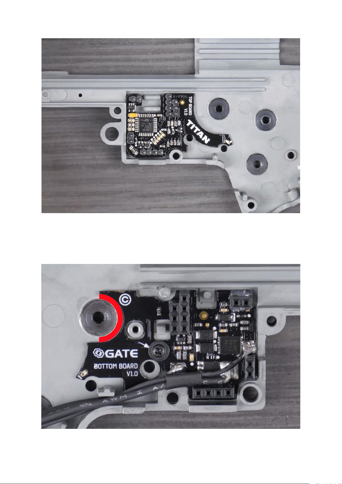
5. Place the bottom board on the bottom part of the gearbox. Do not use
a screw yet. Check if the bottom board is laid at in the gearbox.
6. Make sure the electronic components do not touch the gearbox case.
81

7. Use the insulation (black) washer from the kit. ATTENTION! The insulation washer must
protect the circuit board. The metal screw and metal washer cannot touch the board
directly. It can result in short circuit and TITAN damage what is not covered by the
warranty.
8. Screw on the bottom board to the case. Use the original screw or the one from
the TITAN kit.
82

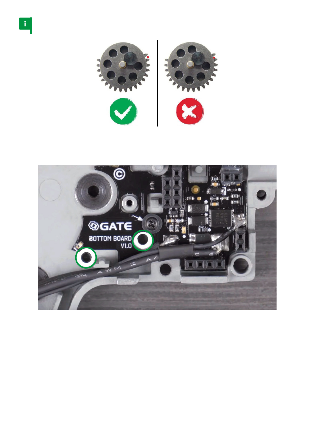
9. Check if the screw sticks out of the gearbox.
10. If so, add metal washer(s) included in the kit. Make sure that the metal washer is placed
between the screw and the insulation washer. It cannot touch the circuit board directly.
83

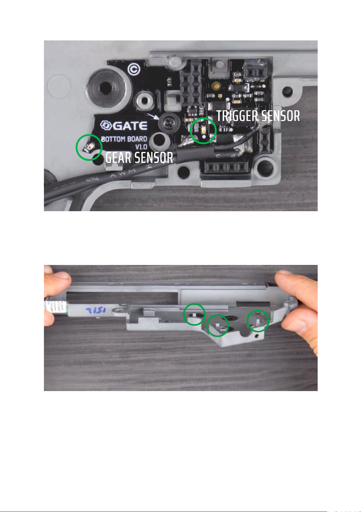
11. Check if the top board ts gearbox without any problems.
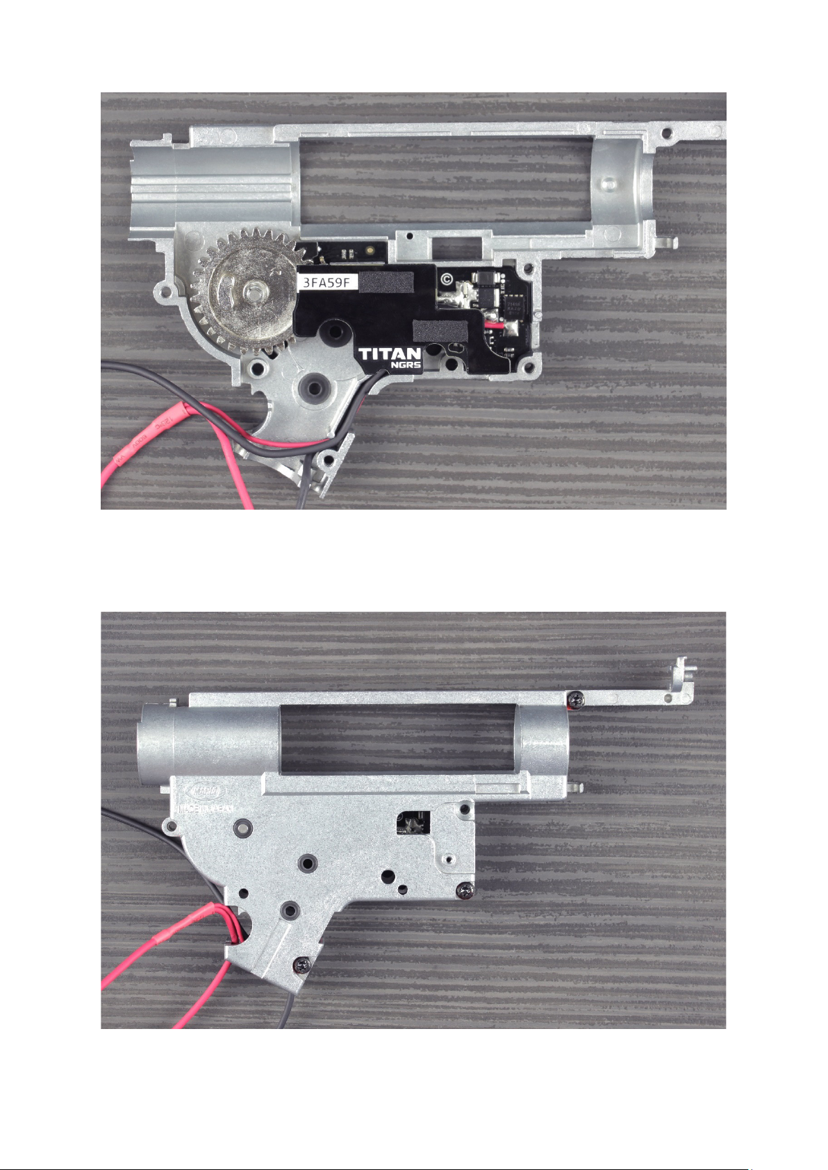
12. Make sure the marked areas are not covered by board or wires. Check if sensors are clean.
84

13. Place the wires in the gearbox shell, in exactly the same
way as in the picture. The order is important.
14. Check if both parts of the gearbox t together perfectly.
85
15. Mount the sector gear and top TITAN board. Make sure that the gear does not touch TITAN.
16. Close the gearbox. Tighten at least three screws.
86

17. Connect the unit with GATE Control Station using USB cable and USB-Link (do not solder
Deans-T connectors yet).
18. Go to Sensors TAB. While moving the gear, observe what happens with the
FULL SECTION/HALF SECTION icons and gear sensors. Please note that
TITAN V2 NGRS is not compatible with Tactical Programming Card.
87

19. Depending on the position of the gear, the FULL SECTION/HALF SECTION icons
should ash alternately. The gear sensors should also ash alternately.
20. Test the bolt catch sensor by moving the lever up and down. Observe
what happens with the BOLT CATCH SENSOR icons. Depending on
the position of the lever, the icons should ash alternately.
88
21. If both sensors work awlessly, you can assemble the gearbox. Do not use too
much grease. In a critical situation, excessive grease may cover a sensor.
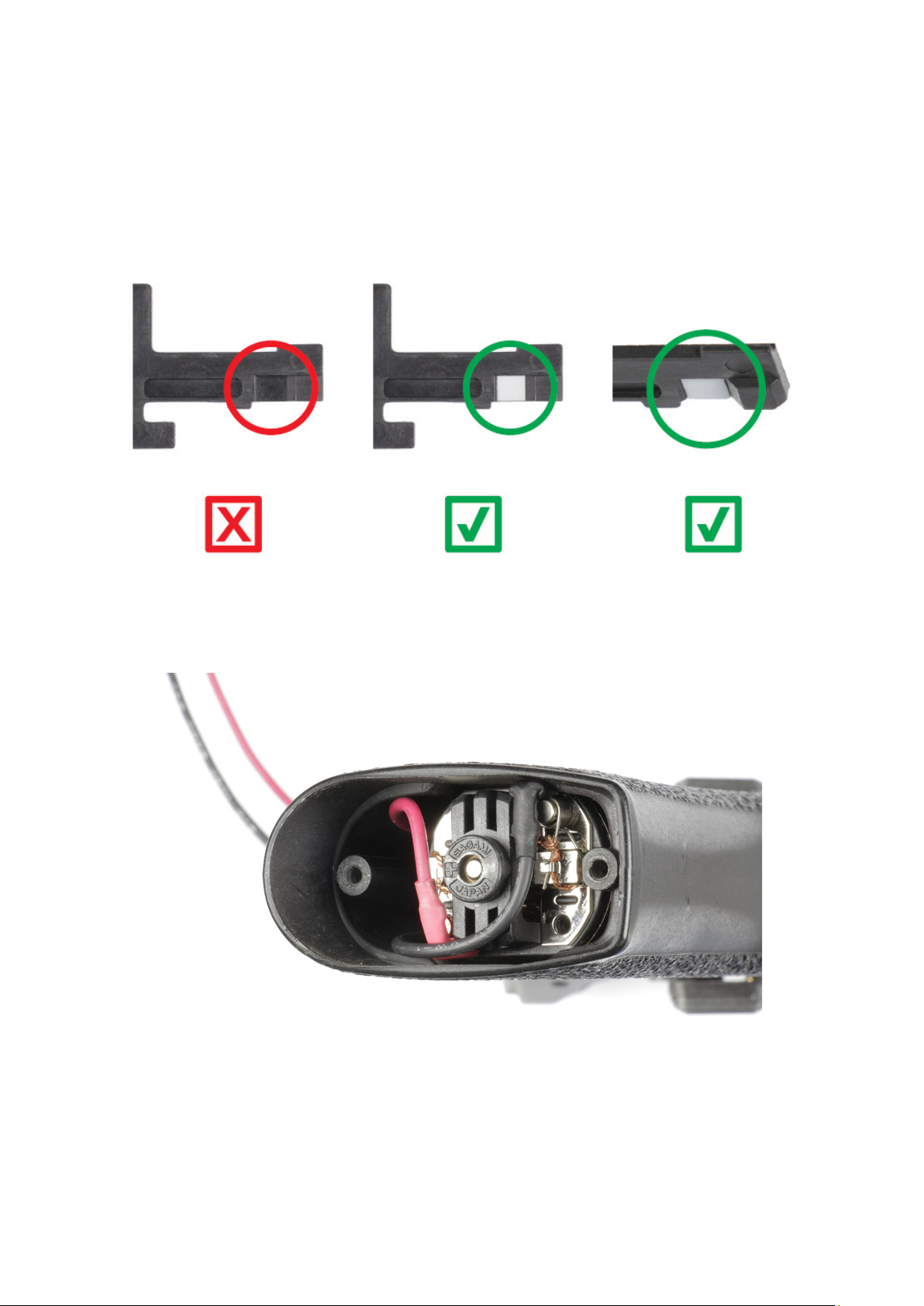
22. Modify the re selector plate. Use solvent to clean re selector plate.
Next, take the stickers shown in the picture below. Take the small sticker
(re selector sticker) and paste on the at surface shown below.
23. The wires in pistol grip have to be placed according to the photo below.
89

24. The wires in buer tube have to be placed according to the photos below.
90
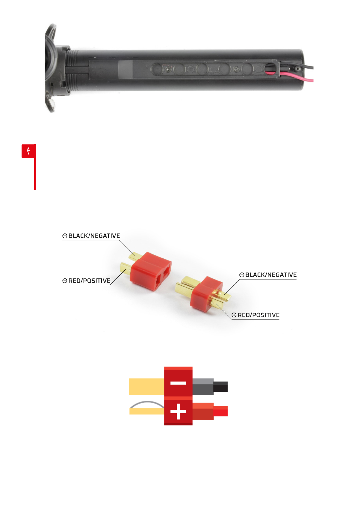
Warning
Pay attention to correctly solder positive and negative TITAN wires to
the connector. Otherwise, aer plugging the battery, the reverse battery
polarity will cause immediate damage to the device. Is not covered by the
warranty and it can lead to re, burn or even battery explosion.
91

25. Put heat-shrink tube on a wire, cover the connector with a thin layer of
solder (always use ux or rosin during soldering, especially when solder
melts. This is necessary to achieve the correct connection).
26. Have a look at the connection and check if it is done properly. Pay
attention to solder – it should ll soldered space correctly and solder
should not be oxidized. Remove excess rosin from the connection.
92

27. Repeat the procedure with black (negative) wire.
28. Prepare the heat-shrink tubes and close them. Heat each heat-shrink tube
carefully from all sides. Do it over the ame of a gas range or lighter.
93
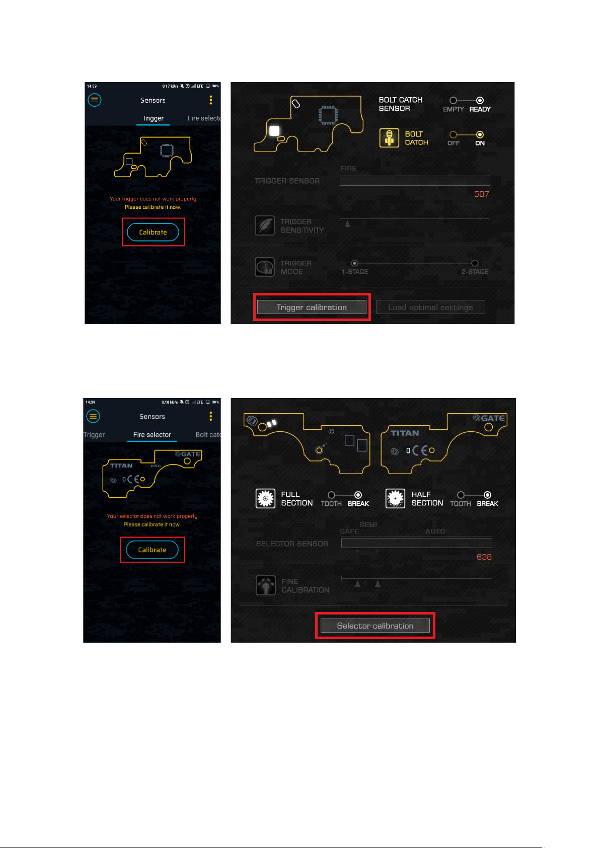
29. If your gun is completely assembled, perform the sensor calibration. Go
to Sensors TAB in GATE Control Station and calibrate the trigger.
30. Then calibrate the re selector.
31. Aer successful calibration your AEG is ready to use.
94

9. Functions
TRIGGER SENSITIVITY ADJUSTMENT
Trigger sensors allow you to control trigger sensitivity. You do not have to disassemble your
AEG. Just use the GATE Control Station app to adjust the trigger to your preferences and level
of skills.
CONFIGURABLE FIRE SELECTOR (gen.2)
Two selector sensors allow you to use up to six re selector modes, including innovative SEMIBURST-AUTO mode:
• SAFE-SEMI-AUTO
• SAFE-SEMI-SEMI
• SAFE-SEMI-BURST
• SAFE-BURST-AUTO
• SAFE-SEMI-BURST/AUTO (short press - BURST, long press - AUTO)
• SEMI-BURST-AUTO (SAFE mode via the fast switch SAFE-SEMI-SAFE)*
*available only for TITAN V3 and V2 NGRS and only aer modications.
CYCLE DETECTION
Thanks to the gear sensor(s), TITAN precisely detects in which position the cycle should nish.
Therefore, even the shortest trigger action produces at least one full cycle. Thanks to the cycle
detection function you get:
• Automatic BURST – there is no need to set the burst time.
You can set the burst between two and 10 shots
• Automatic PRE-COCKING – Pre-cocking is fully operational in SEMI, BURST and
AUTO modes. You can simply set the pre-cocking as high, mid or low;
• Full cycle - when the pre-cocking is o, TITAN ensures that the
gearbox completes a full cycle. You gain a higher reliability.
PRE-COCKING (gen.2*)
Victory in the game is oen a matter of fractions of seconds. Thanks to PRE-COCKING, you gain
a trigger reaction similar to a real gun. It allows for initial spring compression, which speeds up
the trigger response signicantly.
95

There are two PRE-COCKING MODES:
• AUTO MODE – the spring is automatically compressed aer each shot
• TRIGGER MODE – slow trigger action compresses the
spring, and fast trigger action res the shot.
There are also three PRE-COCKING BOOST options: HIGH / MID / LOW.
*Now the pre-cocking is fully operational in SEMI, BURST and AUTO modes and there is no need
to set the pre-cocking boost manually.
You can change Pre-cocking setup via re selector*. Now you do not need to re the shot to
switch pre-cocking mode. You can do it in two ways:
a) Switch re selector to SAFE and pull the trigger
b) Switch re selector to SEMI, re the shot and keep the trigger pulled
While the trigger is pulled you are able to select pre-cocking mode:
• SAFE = Pre-cocking OFF
• SEMI = Pre-cocking SMART
• AUTO = Pre-cocking AUTO.
*You can turn o this feature by marking o “SEL” button.
Please note: using PRE-COCKING increases wear and tear on the gearbox.
BURST (gen.2*)
The burst enables you to shoot a pre-determined number of BBs, which is very useful in
MILSLIM and when using low-caps. The BURST mode is available aer setting the proper
re selector mode. There are two BURST modes:
• FULL – every, even the shortest trigger action res the pre-determined number of
rounds.
• TRIGGER – releasing the trigger while ring stops the burst sequence.
* There is no need to set burst time. You can easily set burst between two and 10 shots.
ROF CONTROL
This enables a reduction in a gun’s rate of re. You use stronger LiPo batteries, and still have a
ROF just like in a real gun.
96

ROF STAB
It allows you to change the way the ROF Control works:
• ON - ROF Control uses PWM (Pulse Width Modulation) to decrease ROF. Thanks to
this, gearbox works smoothly what decreases wear and tear of AEG internal parts.
• OFF - ROF Control adds breaks between shots to decrease
ROF. It gives you more realistic experience.
SNIPER DELAY
It lets you to set delay between each SEMI shot to simulate the delay from reload or recoil.
You can set 0.5s, 1s, 2s or 3s delay. You can enable vibration which will inform you when the
gun is ready to shoot again by choosing “VIB” option.
SMART TRIGGER
We know how vital the fast trigger response is during combat. This is why we have developed
the Smart Trigger function. It enables you to achieve a faster trigger response. It works
with the ROF Control System. During the rst shot, the microprocessor sets the ROF Control
to 100%. Aer the rst shot, it switches to a previously programmed value (e.g. 50%). As
a consequence, the rst shot is red at a full ROF, and subsequent shots at a reduced ROF.
The best results can be achieved by using a battery with a higher than standard voltage. For
example, if you use a 7.4V battery, you can replace it with 11.1V. In this way, you will achieve a
faster trigger response with the same rate of re as with a standard battery.
*Works only when ROF STAB is ON.
TWO STAGE TRIGGER
Enjoy two stage trigger. Activate 2-STAGE trigger mode and set two dierent trigger
sensitivities. Pulling the trigger slightly produces SEMI or BURST re and pulling the trigger
further produces BURST or AUTO re (depending on the re selector mode).
BATTERY PROTECTION (gen.2*)
Protection against over-discharge of the battery. Modern LiPo and LiFe batteries are very
sensitive to over-discharge. If you do not want to damage the battery and you care about
its service life, this protection is indispensable. The microprocessor monitors the battery
voltage constantly. When the voltage drops down to a critical level, it will not allow ring.
*TITAN detects the number of cells automatically. There is no need to reprogram TITAN every
time you replace the battery.
97

LOW BATTERY Warning
When the battery voltage drops to the specied level (in relation to one cell), the motor
will vibrate. You can set: OFF, 3.2V or 3.4V per cell.
SMART FUSE
We have developed an electronic fuse with an accurate current sensor. A combination of
current, voltage and temperature measurements makes your AEG installation highly
reliable. It protects the MOSFET against overheating, overloading and short-circuiting. If
your airso gun becomes jammed, the function protects the motor and battery against
damage.
ADAPTIVE ACTIVE BRAKE
It automatically adjusts the motor’s braking power according to your needs. This prolongs
the lifespan of the motor. Now you can also choose your own value depending on your needs.
MOSFET
Do you want to achieve a higher ROF and faster trigger response? Are you planning a
power upgrade of your gun? In that case, you need a MOSFET.
It targets the energy from the battery directly to the motor, bypassing the mechanical
trigger contacts. As a result, you gain a higher ROF of the gun and a faster trigger response.
BUILT-IN SELF-TEST
This allows you to quickly check whether the TITAN is working properly. If any problem
occurs, the Diagnostic Trouble Codes will indicate where the problem lies.
COATING
Thanks to its special conformal coating, the unit is resistant to atmospheric conditions
(Military Specication: MIL-V-173C).
DEANS-T READY*
The product has factory-tted low-resistance deans-t connector.
*except TITAN V2 NGRS
14.8V LI-PO READY
The TITAN can be used with batteries up to and including 14.8V LI-PO. The minimum
operating voltage is 3.75V and maximum is 17V.
98

PRINTED QUICKSTART
Make your adventure start more easily with a new product. The quickstart contains basic
information and hints.
TRIGGER SENSITIVITY
Allows you to adjust the trigger to your preferences and level of skills.
30-ROUND LIMIT
An AEG can continuously re max. 30 BBs. To re more BBs, you must release the trigger
before. This is a protection against trigger jam. Important: in case of an emergency, you can
also stop ring by switching the re selector
position.
GEAR RATIO
To make the PRE-COCKING working with the highest level of precision you should dene
the gears type in your AEG. Available types: STANDARD, HIGH TORQUE, HIGH SPEED, DSG,
19-TOOTH.
EQUALIZER (dynamic trigger point)
• OFF - to re a next shot, you need to release the trigger until
it reaches the selected trigger sensitivity level
• 2LVL - to re a next shot, it is enough to release the trigger so as it changes
the state of two trigger sensors or ~40% of trigger movement
• 1LVL - to re a next shot, it is enough to release the trigger so as it changes
the state of one trigger sensor or ~20% of trigger movement
1LVL or 2LVL is especially useful when the trigger sensitivity level is very high. Then you do
not need to fully release the trigger while quickly ring on SEMI.
99

10. Legal Notice
Please read the Legal Notice before operating your device and keep it for future reference.
This document contains important terms and conditions with respect to your device. By using
this device, you accept those terms and conditions.
EXCLUSION OF LIABILITY
GATE Enterprise spółka z ograniczoną odpowiedzialnością sp. k. is not liable for any damages,
injuries or accidents of any kind resulting from the use of this product or airso gun with the
product installed, including (but not limited to) incidental or special damages to airso gun,
airso gun parts, batteries and gearbox internals.
DISCLAIMER
GATE Enterprise spółka z ograniczoną odpowiedzialnością sp. k. takes no responsibility
regarding compliance of the product with the requirements of any law, rule or airso
restrictions pertaining thereto.
INTELLECTUAL PROPERTY
Intellectual Property owned by GATE Enterprise spółka z ograniczoną odpowiedzialnością
sp. k., including but not limited to, devices, accessories, parts, soware, documentation, is
proprietary to GATE Enterprise spółka z ograniczoną odpowiedzialnością sp. k. and protected
under Polish laws, EU laws, and international treaty provisions. You may not violate the rights
of the Intellectual Property and you will not prepare derivative works of or reverse engineer
the device or soware. No ownership in the Intellectual Property is transferred to you.
GATE LIMITED WARRANTY POLICY
GATE Enterprise spółka z ograniczoną odpowiedzialnością sp. k. warrants that its Product
is free from manufacturing and material defects at the date of purchase and for a period
of one (1) year from the date of purchase and it is nonextendable. This Limited Warranty is
conditioned upon proper use of Product by Purchaser.
1. This Limited Warranty is valid provided that the owner provides a proof of purchase and
properly completed warranty form.
2. This Limited Warranty does not cover: (a) defects or damage (e.g. mechanical, thermal
or chemical) resulting from accident, misuse (misinterpretation of the instructions),
abuse, neglect, unusual physical, electrical or electromechanical stress, water immersion,
repairs or structural modication of any part of Product, or (b) the Product that has the
serial number removed or made illegible; (c) defects or damage from improper operation,
maintenance or installation, (d) installation of the products.
3. Requests for warranty are processed as soon as possible, not exceeding seven (7) working
days. The company’s obligation under this Limited Warranty shall be limited to providing
replacement of part/s only
100
 Loading...