

Page 1
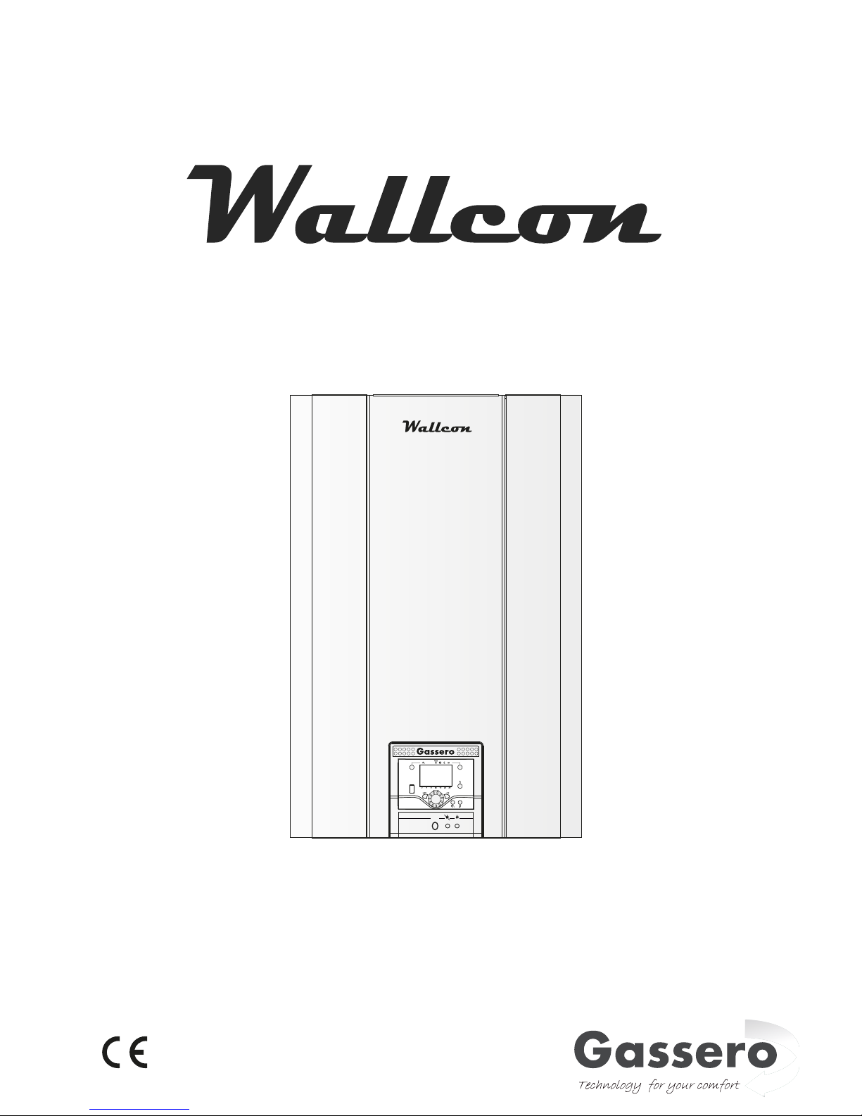
INSTALLATION, USER AND SERVICE MANUAL
WALL HUNG GAS FIRED CONDENSING BOILER
RESET
50
67
42
0051-14
Page 2

Page 3
Table of Contents
Table of Contents
2
IMPORTANT
When carrying out commissioning of the boiler, you are highly recommended to perform the following checks:
–
Make sure that there are no liquids or inflammable materials in the immediate vicinity of the boiler.
– Make sure that the electrical connections have been made correctly and the earth wire is connected to a
weel done earthing system.
– Open the gas tap and check the soundness of the connections, including the burner.
– Make sure that the boiler is set for operation for the type of gas supplied.
– Check that the flue pipe for the outlet of the products of the combustion is unobstructed and has been properly
installed.
– Make sure that any shutoff valves are open and dirt seperators are installed on the return water connection.
– Make sure that the system is charged with water and is thoroughly vented.
– Check that the circulation pump is not locked.
– Purge the system, bleeding off the air present in the gas pipe by operating the pressure relief valve on the gas
valve inlet.
–
The installer must provide the user with instruction in operation of the boiler and safety devices and hand over the
instruction booklet to the user.
–
The images shown in this manual are a simplified representation of the product. In this representation there may be
slight, unimportant differences with the supplied product.
1 Meaning of the symbols and safety instructions . . 3
1.1 Meaning of symbols
1.2 General warnings
2 General . . . . . . . . . . . . . . . . . . . . . . . . . . . . . . . . 5
2.1 Designated use . . . . . . . . . . . . . . . . . . . . . 5
2.3 . . . . . 5Boiler room & ventilation. . . . . . . . . .
2.2 Description of the appliance . . . . . . . . . . 5
. . . . . . . . . . . . . . . . . . 3
. . . . . . . . . . . . . . . . . . . 3
1.3 Safety instructions
. . . . . . . . . . . . . . . . . . . 4
1.4 Regulations and standarts
. . . . . . . . . . . . 4
2.4 Packaging label . . . . . . . . . . . . . . . . . . . . . 6
2.5 . . . . . . . . . . . . . . . . . . . . . . 6Warning label
2.6 Data label . . . . . . . . . . . . . . . . . . . . . . . . . 6
3.1 Wallcon 42/50/67 dimensions . . . . . . . . . 7
3.2 . . . . 8Wallcon 42/50/67 hydraulic diagram
3.3 Wallcon 42/50/67 main components . . . . . . . 9
3 Technical features . . . . . . . . . . . . . . . . . . . . . . . . 7
3.4 Technical data . . . . . . . . . . . . . . . . . . . . . .. 10
4.1.1 Packing . . . . . . . . . . . . . . . . . . . . . . . . 11
4 Instructions for the installer . . . . . . . . . . . . . . . . . . . 11
4.1 . . . . . . . . . . . . . . . . . . . . . . . . 11Installation
4.1.2 Transport . . . . . . . . . . . . . . . . . . . . . . 11
4.1.3 Mounting . . . . . . . . . . . . . . . . . . . . . . . 11
4.1.4 Clearances . . . . . . . . . . . . . . . . . . . . . 12
4.1.6 Water side connections . . . . . . . . . . . . 13
4.1.5 Water quality and treatment . . . . . . . . . 12
4.1.7 Expansion vessel . . . . . . . . . . . . . . . . . 13
4.1.8 Safety valve . . . . . . . . . . . . . . . . . . . . 13
4.1.9 Condansate drain . . . . . . . . . . . . . . . . 13
4.1.10 Frost protection . . . . . . . . . . . . . . . . . 13
4.1.11 Dirt seperation . . . . . . . . . . . . . . . . . . 13
4.1.13 Pump . . . . . . . . . . . . . . . . . . . . . . . . . 13
4.1.12 Automatic air vent . . . . . . . . . . . . . . . . 13
4.2 Installation examples . . . . . . . . . . . . . . . . 14
4.2.1 Single boiler installations . . . . . . . . . . . 14
4.2.2 Cascade installation . . . . . . . . . . . . . . . . 15
4.3 Adjustment of the gas rate . . . . . . . . . . . 16
4.3.1 Description of the adjustment points . . . 16
4.3.2 Combustion values adjustment table . . . 16
4.3.3 Maximum output adjustment . . . . . . . . . 16
4.3.4 Minimum output adjustment . . . . . . . . . 17
4.4 Gas conversion instructions . . . . . . . . . . . 18
4.5 Flue installation instructions . . . . . . . . . . . 19
4.5.1 Flue appliance types . . . . . . . . . . . . . . . 19
4.5.2 Flue installation types . . . . . . . . . . . . . . 20
4.5.3 Flue kit accesories . . . . . . . . . . . . . . . . . 21
4.6 Electrical installation . . . . . . . . . . . . . . . . 22
4.6.1 Wiring diagram . . . . . . . . . . . . . . . . . . . . 22
4.6.2 External probe installation . . . . . . . . . . 23
4.6.3 Outdoor temperature control . . . . . . . . 24
5 Operation . . . . . . . . . . . . . . . . . . . . . . . . . . . . . . . 25
5.1 General . . . . . . . . . . . . . . . . . . . . . . . . . . 25
5.2 Programming . . . . . . . . . . . . . . . . . . . . . 27
5.3 Error codes . . . . . . . . . . . . . . . . . . . . . . 28
5.4 Maintenance codes . . . . . . . . . . . . . . . . 29
6 Maintenance . . . . . . . . . . . . . . . . . . . . . . . . . . . 30
6.1 General . . . . . . . . . . . . . . . . . . . . . . . . . . 30
Comissioning checklist . . . . . . . . . . . . . . . . . . 34
6.2 Maintenance procedure . . . . . . . . . . . . . 30
Service interval record . . . . . . . . . . . . . . . . . . 37
6.3 Troubleshooting . . . . . . . . . . . . . . . . . . . 32
Page 4
1 MEANING OF THE SYMBOLS AND SAFETY INSTRUCTIONS
1.1 MEANING OF THE SYMBOLS
WARNINGS
Keywords indicate the seriousness of the hazard in
terms of the consequences of not following the safety
instructions.
• NOTE indicates that material damage may occur.
• CAUTION indicates that injuries may occur.
• WARNING indicates that serious injury may occur.
• DANGER indicates potentially risk to life.
IMPORTANT INFORMATION
Warnings in this document are framed and
identified with a warning icon which is
shown on the left figure.
Electrical hazards are identified by a
lightning icon surrounded by a warning
triangle.
Important information in cases where there
is no risk of injury material losses is
identified by the symbol shown on the left.
It is bordered by horizontal lines above and
below the text.
After having removed the packaging, check that the
material supplied is intact and complete; if this is
not the case, contact with GASSERO or dealers.
The WALLCON Series b oilers must be installed by
authorized person as detailed under any current
standards and law applicable and with the instructions provided by Gassero in the manual given
with the appliance.
The boiler must be used for the purposes it has
been expressly manufactured. Gassero declines
all contractual and extra-contractual liability for
damage caused to persons, animals or things, due
to errors in installation, control, servicing or improper use.
In case of the water leakage, disconnect the boiler
from the mains power supply, close the water sup ply and promptly notify Gassero or other authorized
qualified personnel.
Periodically check that the condensate drain is free
of blockages.
Periodically check that the operating pressure of
the water circuit when cold is 1.5 bar and less than
the maximum limit specified for the appliance. If this
is not the case, contact with Gassero or other aut horized qualified personnel.
If the boiler is not used for an extended period, the
following operations must be completed:
- move the main system switch to "off"
- close the fuel cock and the water cocks on the cen tral heating system
- empty the central heating system if there is the risk
of frost.
Maintenance and servicing must be done once a year.
This manual is an integral part of the boiler and as a
consequence must be kept with care. If the manual
is damaged or lost, contact with Gassero to supply
a new copy.
PLEASE READ THESE INSTRUCTIONS CAREFULLY
BEFORE STARTING INSTALLATION.
THESE INSTRUCTIONS ARE APPLICABLE TO THE
GASSERO BOILER MODELS WRITTEN ON THE
FRONT COVER OF MANUAL ONLY AND MUST NOT
BE USED WITH ANY OTHER BOILER MODELS.
THIS APPLIANCE MUST BE INSTALLED BY A GAS SAFE
REGISTERED, AUTHORIZED PERSON. FAILURE TO
INSTALL CORRECTLY COULD LEAD TO PROSECUTION.
IF YOU HAVE ANY QUESTION CONTACT THE GASSERO
TECHNICAL SERVICE. ([email protected],
PLEASE LEAVE THESE INSTRUCTIONS WITH THE
COMPLETED INSTALLATION CHECKLIST, AND USER
USER MANUAL WITH THE OWNER OR AT THE GAS
METER AFTER INSTALLATION OR SERVICING.
THE INSTALLATION AND COMISSIONING CHECKLIST
CAN BE FOUND IN BACK PAGES THE MANUAL.
1.2 GENERAL WARNINGS
Actions that absolutely must not be
carry out identified by the figure on left
Meaning of the Symbols and Safety Instructions
3
+90 216 394 09 85 )
Page 5
The boiler must not be used by children or invalid
persons without supervision.
Electrical devices or appliances, such as switches,
household appliances, etc. must not be used if there
is the smell of gas or unburned fuel. In this case :
- ventilate the room by opening doors and windows;
- close the fuel stopcock;
- promptly contact Gassero, your gas supplier or
other professionally qualified personnel.
Do not touch the boiler when bare feet or with wet
parts of the body.
No service or cleaning operations may be performed without first having disconnected the boiler
from the mains power supply , moving the main
system switch to "off".
The safety or control devices must not be adjusted
w
ithout the authorisation and written instructions
from the manufacturer of the boiler.
Do not pull, remove or twist the electrical cables
coming out of the boiler , even if the appliance is
disconnected from the mains power supply.
The ventilation openings in the room where the
appliance is installed must not be plugged or reduced in size and must comply with any current standards and law applicable.
Do not switch off the boiler if the outside temperature may decrease below ZERO (risk of freezing).
Do not leave flammable substances in the room
where the boiler is installed.
The packaging material must not be dispersed in
the environment or left within the reach of children
as it is a potential source of hazard. It must be
disposed of according to the legislation in force.
Alterations to parts connected to the appliance
Do not carry out any alterations for following parts:
- the boiler
- to the gas, air, water supply pipes and electrical
- to the flue pipe, safety valve and its drain pipe
- to the constructive components which influence the
When tightening or loosening the screw connections,
use only adequate tool. The improper use and/or
the use of inadequate equipment can cause damages
If you smell gas :
If you smell gas follow these safety indica
tions:
Do not turn on or turn off electrical switches
Do not smoke
Do not use the telephone
Close the mains gas tap
Open all windows and doors where the gas leakage
Contact the gas society or a company specialized in
Indications for appliances operating with propane gas
ensure yourself that before installing the appliance the
For a correct purging of the tank contact the liquid gas
supplier or a legalley authorized person .
If the tank has not been correctly purged proble
ms
could occur during ignition. If this occurs contact the
appliance’s safe operation
(for example water or gas leakages).
installing and servicing heating systems
gas tank has been purged.
liquid gas tank’s supplier.
1.4 REGULATIONS AND STANDARTS
Current Gas Safety (Installation & Use) Regulations:
All gas appliances must be installed by a competent
person in accordance with the above regulations;
The appliance must be installed in accordance with, and
comply to, the current: Gas Safety Regulations, IEE
Regulations, Building Regulations, Building Standards
and any other local requirements.
Directives:
• 2009/142/EEC gas appliance directive
• 92/42/EEC boiler efficiency directive
• 73/23/EEC low voltage directive
• 89/336/EEC EMC directive
• 97/23/EC pressure equipment directive
• any relevant requirement of the local authority.
EN 483 Gas-fired central heating boilers.
Type C boilers of nominal heat input not
exceeding 70 kW.
EN 677 Gas-fired central heating boilers. Specific
requirements for condensing boilers with
a nominal heat input not exceeding
70 kW.
Installation not exceeding 70 kW rated input
Meaning of the Symbols and Safety Instructions
4
1.3 SAFETY INSTRUCTIONS
Page 6
2 GENERAL
the following wall-mounted condensing gas boilers:
The Wallcon 42/50/67 is suitable for use as a single boiler or as
part of a cascade system.
CE LABEL
The appliance complies with the basic
requirements of the relevant European
directives.
Conformity has been substantiated by the
proper documents which, together with
the declaration of conformity, are filed
with the manufacturer.
•
Wallcon 50
The boiler may only be used to heat up water for heating
systems as standard and/or domestic hot water (DHW)
systems with the connection of DHW tank.
The boiler can be installed either as a single system or as
part of a multiple system (cascade system). A cascade
system enables several boilers of this type to be
connected together, where maximum of 16 boilers with
can be connected together.
Special cascade units (accessories) have been
developed to enable this boiler to be installed in a
cascade system. Every cascade unit includes an
installation frame, horizontal headers, connection pipes
for the boiler, main gas pipe and vertical low loss header.
Also, cascade units are available for installing the boilers
inline or back-to-back. These cascade units make
installing a cascade system easier and less labour
intensive. Please contact your dealer or the
manufacturer for further information about cascade
systems.
CAUTION:
Damage to the installation due to frost.
Install the heating system in a room
which is free from frost.
WARNING:
Fire hazard due to flammable materials or
liquids.
Do not store any flammable materials or
liquids in the direct vicinity of the boiler.
CAUTION:
Boiler damage due to contaminated
combustion air or contaminated air in the
boiler room.
Never use the boiler in an environment which
contains lots of dust or aggressive chemicals.
Such as spray shops,hairdresser's shops,
locations where tricholorethylene or hydrogen
halides (e.g. contained in aerosols, certain
adhesives, solvents or detergents, paints)
and other aggressive chemicals are used or
stored.
2.1 DESIGNED TO USE
2.3 BOILER ROOM & VENTILATION
These installation and maintenance instructions apply to
General
5
The WALLCON is a wall-hung condensing boiler, for
CH and DHW(with DHW tank) purposes, with pre-mix
burner, made up of stainless steel heat exchanger.
The
WALLCON boilers can be combined in a cascade
configuration with other heat generators to create
modular heating plants made up of boilers connected to
the same water circuit and with electr onic controllers
communicating via bus. The heat output of each boiler
o
unit reaches 42kW (100%, 50
o
C / 30 C) for Wallcon 42
,
o o
51kW (100%, 50 C / 30 C) for Wallcon 50 and 67 kW
2.2 DESCRIPTION OF THE APPLIANCE
The individual heating units in cascading configuration
can be activated, as well as by simple rotation, in such a
way that when a certain percentage of output is reached
by the first unit, the other units start automatically, all with
the same load factor.
The main features of the
WALLCON Boilers are:
- cold burner door with premix burner
- output from 8.5 to 42 kW (models 42 M and 42 S)
- output from 8.5 to 51 kW (models 50 M and 50 S)
-
- micropr ocessor control with self-diagnosis, shown on
LED and the display
- frost protection function activated according to the outside temperature and/or the temperature of the boiler
- fitted for room thermostat in the high and low temperature zones(optional)
- outside probe to enable the climate control function
- post-cir culation function for the central heating and
DHW circuits
- priority settable on the DHW, high or low temperatur e
circuit
-
- low investment costs for cascade operations ( slave
- chimney sweep function
-
-
solar system & swimming pool control functions
models can be controlled by Master models, without
using any display modules in slave units)
•
Wallcon 67
•
Wallcon 42
for Wallcon 67 modulated from 16 % to 100%.
output from 16 to 67.1 kW (models 67 M and 67 S)
Page 7
General
6
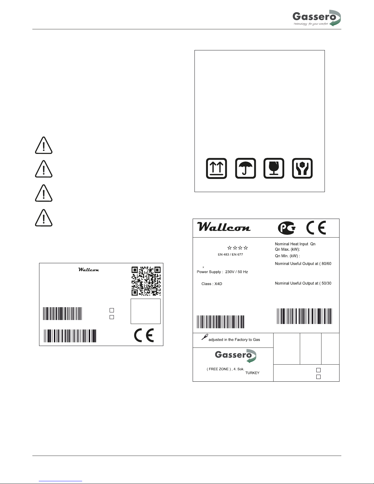
2.4 PACKAGING LABEL
2.5 WARNING LABEL
WARNINGS !
.Read the technical instructions before installing
the boiler.
.Installation and comissioning must be done by
authorized qualified technicians.
.The boiler may only be installed in a room which
complies with the appropriate ventilation require-
2.6 DATA LABEL
Wall Hung Gas Condensing Boilers
Model : Wallcon
Efficiency Level :
Standards :
Flue (appliance) Types : B23, C13, C33,
C43, C53, C63, C83
Production Year :
IP
Istanbul Endustri ve Ticaret Serbest Bolgesi
Parsel 110
34957 , Tuzla, Istanbul,
www.gassero.com
ATTENTION : The boiler is
Pressure of G20 - 21 mbar .
Pressure
Gas
Category
Gas
Destination
Countries of
NO Class : 5
Power Consumption :
Max. Working Temperature :
o
85 C
Max. Working Pressure(PMS) : bar
o
C)
o
C)
.Read the user instructions before operating the
boiler.
ments and which is seperated from living rooms.
The Wallcon condensing boilers must be installed in rooms
used exclusively for this purpose, provided with adequately
sized ventilation openings, in compliance with any current
standards and low applicable. If the combustion air is taken
from outside the room where the boiler is installed,
Wallcon boilers operates as a room-sealed appliance (type C).
Provide enough clearance to access the safety and
control devices and to carry out the servicing operations.
Check that the index of protection of the boiler is
suitable for the characteristics of the room where
the appliance is installed.
If the boilers operate on gas fuel with a higher specific
weight than air, the electrical parts must be located at
least 500 mm from the floor.
The boilers cannot be installed outside as they are
not designed for outdoor operation.
When installing and operating the boilers it is necessary to
keep a safe 200 mm distance from combustible materials
with combustibility degrees B,C1,C2 .
For easily flammable materials with combustibility degree C3
which burn quickly and by themselves also after the ignition
source removal the safe distance is doubled it means 400 mm.
0051 -14
1 2 3 4 5 6 7 8 9 0 1 2 3
Product Model :
Serial Number :
1 2 3 4 5 6 7 8 9 0 1 2 3
Heat Output :
Gas Type : 2H G20-21 mbar-N.Gas
Countries of
Destination
1 2 3 4 5 6 7 8 9 0 1 2 3
Product Code :
Serial Number :
Product Code :
1 2 3 4 5 6 7 8 9 0 1 2 3
MASTER
SLAVE
Pn Max. (kW) :
Pn Min. (kW) :
Pn Max. (kW) :
Pn Min. (kW) :
MASTER
SLAVE
Page 8
3 TECHNICAL FEA
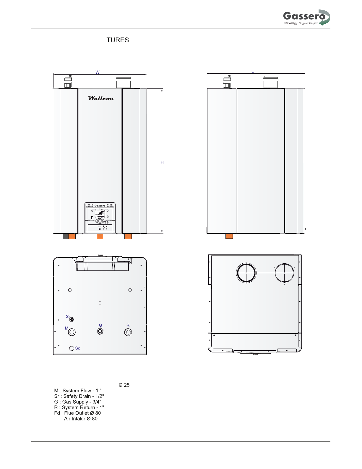
3.1 WALLCON 42/50/67 CONNECTIONS AND DIMENSIONS
CONNECTIONS :
Technical features
7
Fd Ad
Sc : Condensate discharge -
Ad :
DIMENSIONS :
Wallcon 42
W : 446 mm
L : 390 mm
H : 654 mm
Wallcon 67
W : 446 mm
L : 480 mm
H : 654 mm
Wallcon 50
W : 446 mm
L : 390 mm
H : 654 mm
Page 9
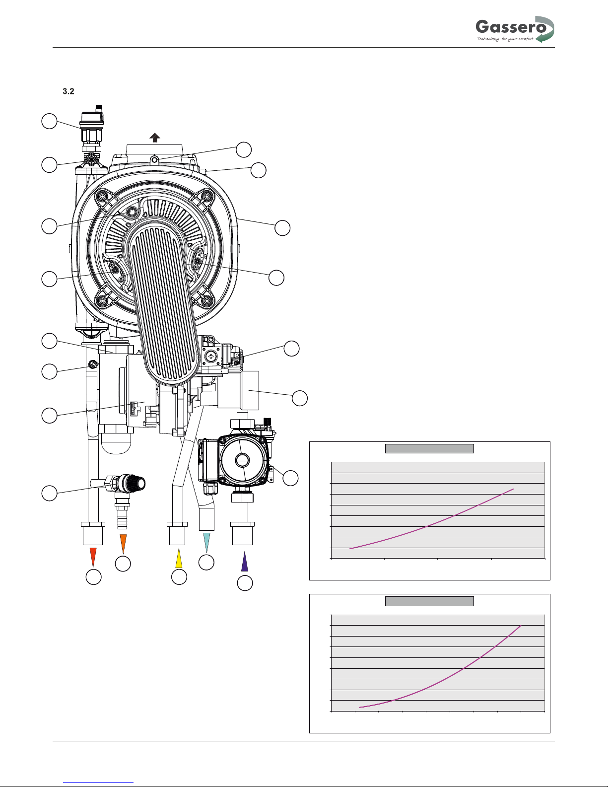
KEY
1 - Pump
2 - Venturi Adapter
3 - Gas Valve
4 - Ignition Electrode
5 - Heat Exchanger
6 - Thermal fuse
7 - Flue Gas Temperature Sensor
8 - Automatic Air Vent
9 - Manuel Air Vent
10 - Flue gas tempertaure sensor
11 - Ionization electrode
12 - Syphon
13 - NTC sensor
14 - Fan
15 - Safety Relief Valve
Technical features
8
Water pressure losses on Wallcon 67
0
10
20
30
40
50
60
70
80
90
0 500 1000 1500 2000 2500 3000 3500 4000 4500
Water flow rate(L/h)
Water pressure losses (KPa)
Water pressure losses on Wallcon 42/50
6
11
16
21
26
31
36
41
46
51
800 1200 1600 2000 2400
Water flow rate(L/h)
Water pressure losses (KPa)
1
2
3
4
5
6
7
8
9
10
11
12
13
14
15
R
G
Sc
M
Sr
WALLCON 42/50/67 HYDRAULIC DIAGRAM
Page 10
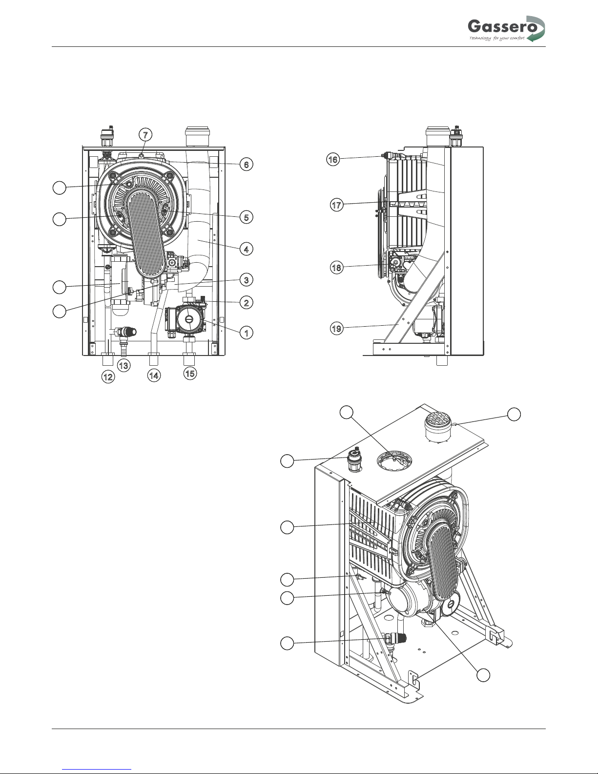
3.3 WALLCON 42/50/67 MAIN COMPONENTS
Technical features
9
KEY
1 - Pump
2 - Pump Air Vent
3 - Venturi Adapter
4 - Air intake flexi duct
5 - Ignition Electrode
6 - Flue thermalfuse
7 - Flue Gas Temperature Sensor
8 - Flame Observation Glass
9 - Ionization Electrode
10 - Syphon
11 - Venturi
12 - Water Flow Connection
13 - Safety Drain Connection
14 - Gas Supply Connection
15 - Water Return Connection
16 - Manual Air Vent
17 - Heat Exchanger Bracket
18 - Gas Valve
19 - Chassis Support Bracket
20 - Flue Outlet
21 - Automatic Air Vent
22 - Heat Exchanger
23 - Water Flow NTC Sensor
24 - Water Return NTC Sensor
25 - Safety Relief Valve
26 - Fan
27 - Air Intake Terminal
16
17
19
18
21
22
23
24
25
20
27
26
1
2
3
4
5
8
7
9
10
11
6
12
13
14
15
Page 11
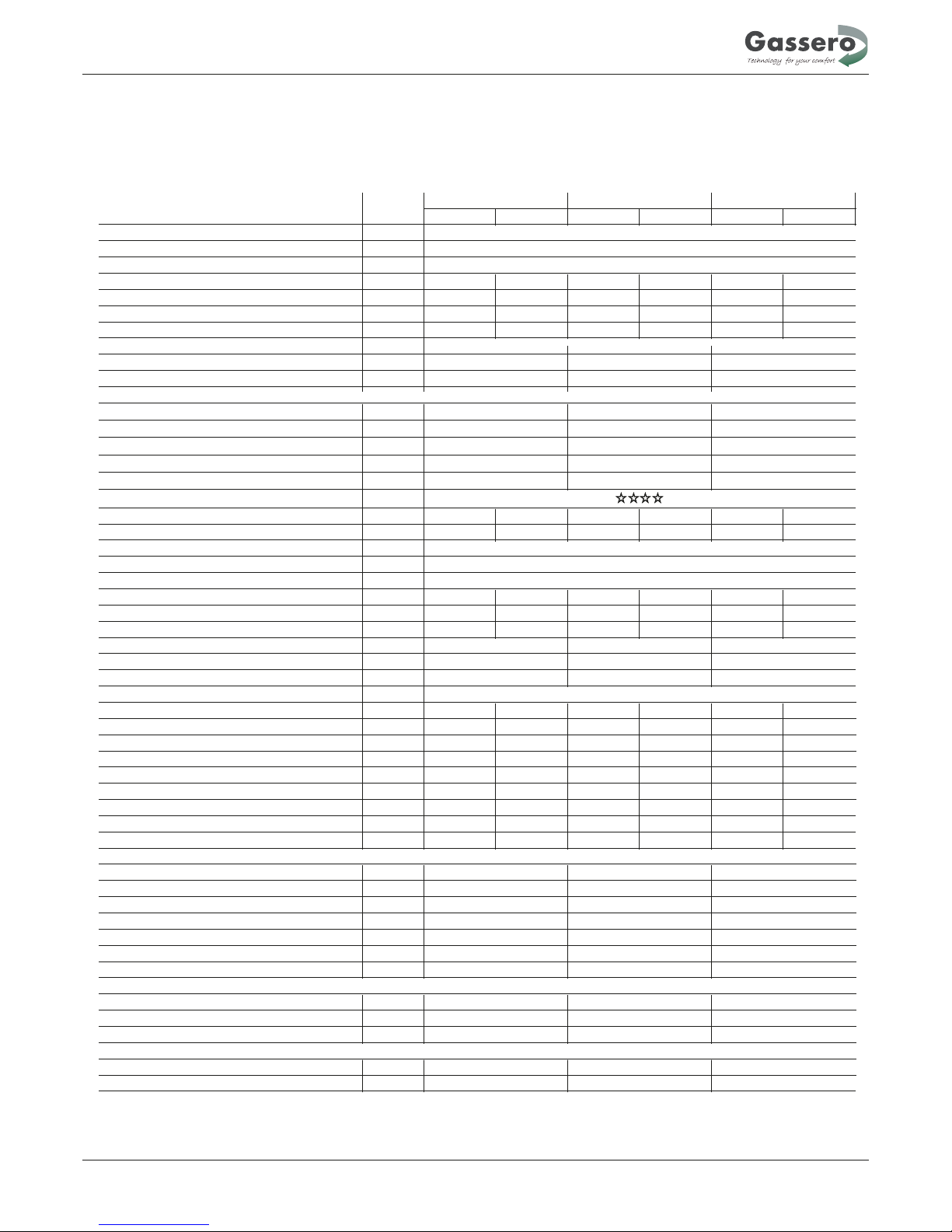
3.4 TECHNICAL DATA
Technical features
10
min. max. min. max. min. max.
Installation types
Gas categories
Fuel type
Nominal heat input Qn kW 8 39,4 8 48 15 63
Nominal heat output Pn at ( 80 - 60
o
C )
kW 7,6 38,3 7,6 46,3 14,4 61
Nominal heat output Pn at ( 50 - 30
o
C )
kW 8,5 42 8,5 51 16 67,1
Working pressure bar 0,8 3 0,8 3 0,8 4
Max. working temperature
o
C
Water content l
Condensate discharge rate kg/h
Efficiency at Q
min
( 80 - 60 oC )
%
Efficiency at Q
max
( 80 - 60 oC )
%
Efficiency at Q
min
( 50 - 30 oC )
%
Efficiency at Q
max
( 50 - 30 oC )
%
Partial load return 30
o
C
%
Efficiency level
Flue gas temperature ( 50 - 30
o
C )
o
C
42 52 43 64 39,8 62,7
Flue gas temperature ( 80 - 60
o
C )
o
C
63 75 63 82 62,9 82
Gas nozzle (G20) mm
Gas nozzle (G25) mm
Gas nozzle (G31) mm
CO
2
emissions (G20)
% 8,9 9,2 8,9 9,2 8,9 9,2
CO
2
emissions (G25)
% 8,9 9,4 8,9 9,4 8,9
9,2
CO
2
emissions (G30)
% 10,6 11,1 10,6 11,1 10,7 11,1
NO
x
emissions (G20)
mg/kWh
NO
x
emissions (G25)
mg/kWh
NO
x
emissions (G30)
mg/kWh
NO
x
class
Combustion products output mass (G20) g/sec 3,7 17,7 3,7 21,6 6,90 28,40
Combustion products output mass (G25) g/sec 3,7 17,4 3,7 21,3 7,00 28,40
Combustion products output mass (G30) g/sec 3,5 16,6 3,5 20,2 6,50 26,50
Gas flow rate (G20)
m
3
/h
0,9 4,2 0,9 5,1 1,57 6,7
Gas flow rate (G25)
m
3
/h
1,0 4,8 1,0 5,9 1,82 7,8
Gas flow rate (G30)
m
3
/h
1,2
0,3
0,3 1,5 0,47 2,0
Fan speed (G20) rpm 1250 5100 1250 6000 1700 6500
Fan speed (G25) rpm 1300 5100 1300 6250 1700 6500
Fan speed (G30) rpm 1200 4750 1200 5750 1350 5900
System flow "
System return "
Gas inlet "
Safety drain "
Condensate discharge
Flue outlet
Air intake
Power supply V/Hz
Power consumption W
Electric insulation class IP
Dimensions mm
Weight kg
25
Efficiency&Combustion
2,5
94,9
97,1
7,5
35,68
39,77
42,65
2,5
Model Wallcon
42
7,7
9,5
5,5
94,9
96,4 96,9
106,0
106,8
106,0
106,3
106,9106,7
107,2
106,5
107,9
67
3,5
96,0
14
85
10
50
B23, C13, C33, C43, C53, C63, C83
2H, 2E, 2LL, 3+ and 3B/P
Natural Gas / LPG
34,1
37,89
73,53
X4D
25
80
80
230 - 50
250
1
1
3/4
1/2
42,99
38,38
72,81
446x390x654 446x390x654 446x480x654
5
80
80
230 - 50
280
X4D
1
1
3/4
80
1
1
1/2
33 33 44
1/2
25
Electrical
Connections
3/4
230 - 50
220
X4D
80
Dimensions & Weight
mm
mm
mm
Page 12
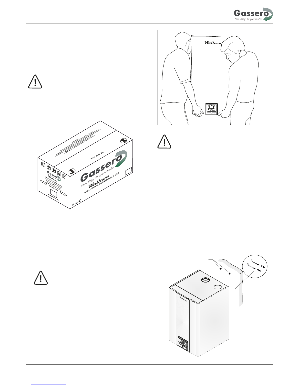
The Wallcon boilers are supplied fully assembled in a
strong cardboard box.
After having unpacked the boiler check that it is intact and
undamaged.
Keep the packaging material (cardboard box,
plastic bags, polyester protection etc.) out of
th e reach of ch i ldren as th e y can be
dangerous.
GASSERO refuses all liability for injury to persons,
animals or damage to property deriving from
not having respected the above mentioned
recommendations.
In the packaging, in addition to the boiler, you can also find
the following contents:
- Installation and service manual
- Warranty card
- Flue adapter for smoke evacuation
4.1.2 TRANSPORT
CAUTION: Damage to the installation due to
impacts.
The boiler contains parts which can be
damaged by impacts.
During further transport all parts must be
protected against impacts.
Obey the transport symbols and
instructions on the packaging.
To lift and carry the boiler, place one hand at the bottom of the
boiler and the other hand on its top.
CAUTION: Damage to the unit due to
it being lifted and carried incorrectly.
Do not hold the boiler over the control
panel to lift and carry it.
Place the boiler in its packaging on the handtruck and secure
it with a strap if necessary.
Carefully transport the boiler to the installation
place.
The Wallcon Boiler must be secured to a solid brick
or concrete wall using the wall hanging brackets.
For installation:
-
Position the bracket on the wall using correct
level to make sure that the holes are perfectly
horizontal(1)
- Mark the fastening holes on the wall (1)
- Drill the holes and insert the expansion plugs(2)
- Fasten the bracket to the wall using the screws
- Hook the boiler to the bracket.
4.1.3 MOUNTING
Instructions for the installer
11
4 INSTRUCTIONS FOR THE INSTALLER
4.1 INSTALLATION
4.1.1 PACKING
- Wall hanging brackets
1
2
RESET
Page 13
4.1.5 WATER QUALITY AND TREATMENT
If the water might contain aluminium particles, this should
be maximum 8,5 ppm. If there is any doubt of the water
staying free of any kind of debris/contamination in the period
after installing, one should install a plate heat exchanger
to separate the boiler circuit from the heating circuit. To
avoid to the maximum any presence of oxygen in the
system, we recommend to prevent as much as possible
air intake and water leakage during installation. Power flush
the pipes and radiators thoroughly to remove all fluxes and
debris before connecting the boiler to the central heating
sy s t e m i n ac c o r d a n c e w i t h loc a l reg u la t i o n s .
Instructions for the installer
12
The manufacturer declines any liability for damage caused to
the boiler by failure to install or inadequate installation of
this filter. Before switch on the boiler, water must be circulate at
least 2 hours for elimination the impurities from the system
trough the micro impurity seperator. In the end of the operation,
safety drain valve must be opened for removing the impurities.
It is also possible to use plate heat exchangers according the
system characteristics. In any case, micro impurity seperators
must be used in the system in the boiler. Before installation,
carefully wash all the pipes of the system to remove any
residuals or impurities that could affect proper operation of the
unit. Filter must also be installed on the system return piping to
prevent impurities or sludge from the system clogging and
damaging the boiler.
CAUTION:
Boiler damage due to corrosion.
NOTE:
Damage to the installation due to insufficient or improper
cleaning and maintenance.
Inspect and clean the heating system as required once a
year.
Carry out maintenance as required.
Immediately remedy faults. This will avoid further damage
to the system!
DO NOT treat the water with antifreeze.
Suitable chemicals and their use should be discussed with a
specialist water treatment company prior to carrying out any
work (environmental aspects, health aspects). The specification
of the system and manufacturers recommendations must
be taken into account, along with the age and condition of
the system. New systems should be flushed thoroughly to
regulations to remove all traces of flux, debris, grease
and metal swarf generated during installation. Care to be
taken with old systems to ensure any black metallic iron oxide
sludge and other corrosive residues are removed, again by
power flushing, ensuring that the system is drained completely
from all low points. It is important to check the inhibitor
concentration after installation, system modifications, filling the
system and every service in accordance with these instructions.
For the correct dosage and the suitability of inhibitors for use
with our boilers and for further information on water treatment
or system cleaning we advise direct contact with Gassero
service.
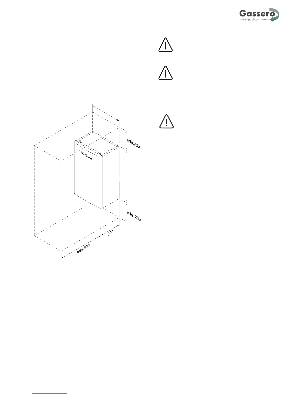
The gas and water connections are located on the bottom of
the boiler whilst the air intake and flue outlet is located on the
top of the boiler. The boiler is supplied as standard with pipework tails to allow connections facing downwards. For installation,
servicing and inspection min. 600 mm in front of the boiler is
required. If this free space is obtained by opening a door or
removing a panel, the boiler may be installed for instance in a
closed cupboard. For ease of installation we recommend
clearances of 0.5 cm at the side so that the unit is easy to open,
with a free space of 25 cm under the appliance and 25 cm above
the appliance, as the minimum requirement.
4.1.4 CLEARENCES
The pH value of the water must fall within the following limits:
7 < pH < 9 in non-treated water. This pH value is achievable
after steady conditions when after filling the mains network
water ( pH around 7 ) inside the installation and the air
elimination operation has been done.Treated water hardness
must within limits 7 < pH < 8,5
The plumbing system must be cleaned using with suitable registered produts before starting the installation of the boiler.
Neutral, non-acidic and non-alkali cleaners( SENTINEL X300,
X400, FERNOX ) must be used for preventing the metal,
plastic and rubber parts in the installation system. Please obey
the instructions of the manufacturer, when using these type of
cleaners.
Note: Rust particles and impurities in the heating system can
caused problems.( overheating, un-efficient and noisy work)
Problems and damages due to wrong installations and wrong
plumbing systems is out of warranty.
Page 14
4.1.6 WATER SIDE CONNECTION INSTRUCTIONS
The heating capacity of the unit must be previously established
current regulations. The system must be provided with all the
components for correct and regular operation. In particular,
provide for all the protection and safety devices prescribed by
current regulations for the complete system.
We strongly recommend to install two ball valves
under the boiler, so the boiler can be isolated from
the heating system when needed.
4.1.7 EXPANSION VESSEL
W
therefore its connection must be carried out by the qualified
installer. The capacity of the expansion vessel must be chosen
and installed to match the capacity of the central heating
system and the static pressure. We suggest you install the
expansion vessel in the return line of the central heating
system. It can be combined with the drain valve for servicing.
4.1.8 SAFETY VALVE
Safety valve outlet must be connected to collection pipe to
prevent water spurting onto the floor in case of overpressure
in the heating circuit. Otherwise, if the discharge valve cuts in
and floods the room, the boiler manufacturer cannot be held
liable.
4.1.9 CONDENSATE DISCHARGE
The condensate drain is in the left side at the bottom of the
boiler and has a 25mm hose discharge. Connect this flexible
condensate drain. Metal lines are not allowed. Blockage of this
drain may cause damage to the boiler. The drain connection is
correct when the condensate can be seen flowing away, e.g.
using a funnel. Any damage that may occur is not covered by
the warranty of the boiler. There should be an open connection
between the condensate hose from the boiler, to the sewage
system. An under pressure in the sewage system should never
be able to suck on the boiler condensate drain hose. The
condensate drain must be connected in accordance with
current regulations.
Do not use the water system pipes to earth electrical
appliances.
4.1.10 FROST PROTECTION
Wallcon series boiler has built-in frost protection, automatically
activating the central heating pump when the boiler return
will shut down as soon as the return temperature has reached
demanded point. The above-mentioned temperatures relates
boiler. This Frost Protection provision is for the boiler only and
not for the all system.
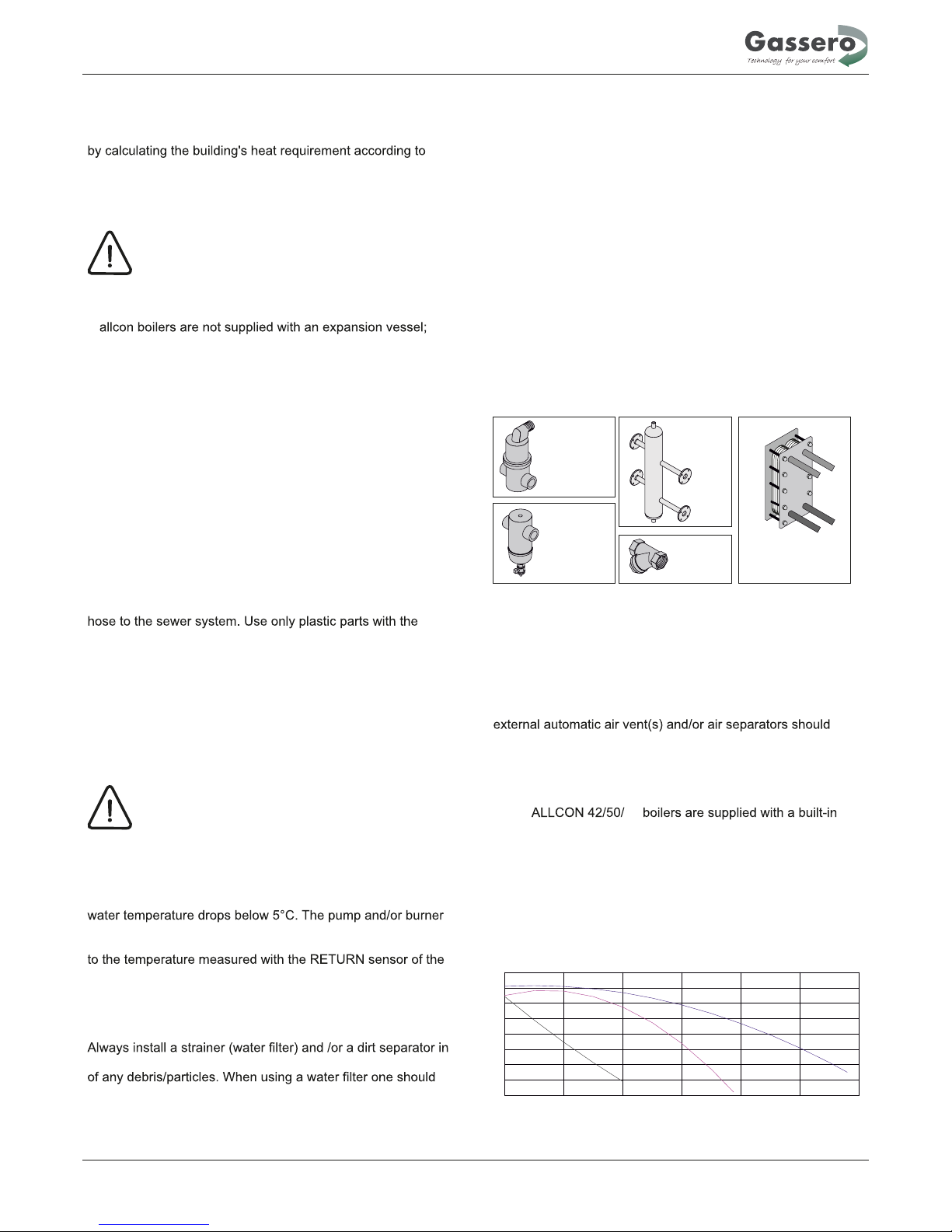
4.1.11 DIRT SEPERATION
the return of the boiler is such a way that the boiler water is free
check weekly after installation to determine the strainer cleaning
interval.
Instructions for the installer
13
including an air bleed valve so the strainer can be isolated from
the heating circuit for servicing. Clean water is important,
blocked heat exchangers do not fall under warranty. The filter
should be installed when replacing boilers in existing systems.
The manufacturer declines any liability for damage caused to
the boiler by failure to install or inadequate installation of
this filter. Before switch on the boiler, water must be circulate at
least 2 hours for elimination the impurities from the system
trough the micro impurity seperator. In the end of the operation,
safety drain valve must be opened for removing the impurities.
It is also possible to use plate heat exchangers according the
system characteristics. In any case, micro impurity seperators
must be used in the system in the boiler. Before installation,
carefully wash all the pipes of the system to remove any
residuals or impurities that could affect proper operation of the
unit. Filter must also be installed on the system return piping to
prevent impurities or sludge from the system clogging and
damaging the boiler.
We advise to mount valves before and after the strainer
There is an automatic air vent mounted in the boiler to remove
air from the water circuit. This automatic air vent is only for
eliminate the air in the heat exchanger of the boiler. One or more
always be installed in the heating system to eliminate air trapped
in the heating circuit.
4.1.13 PUMP
The W
circulation pump with 3-position electric speed control. The
pump is the single-phase type (230 V - 50 Hz). To ensure
optimal boiler operation, in the case of new systems (single
pipe and module) it is recommended to use the pump at
maximum speed. The pump runs when heat is required. When
heat is no longer required, the pump will continue to run for
another 3 minutes before it stops. The 24-hour cycle starts as
soon as the power supply to the boiler is activated.
4.1.12 AUTOMATIC AIR VENT
Dirt
seperator
Air
seperator
Low loss
header
Plate heat
exchanger
Filter
0.0 0.5 1.0 1.5 2.0 2.5 3.0
QH Chart
8
7
6
5
4
3
2
1
0
H [m]
3
Q [m /h]
67
Page 15
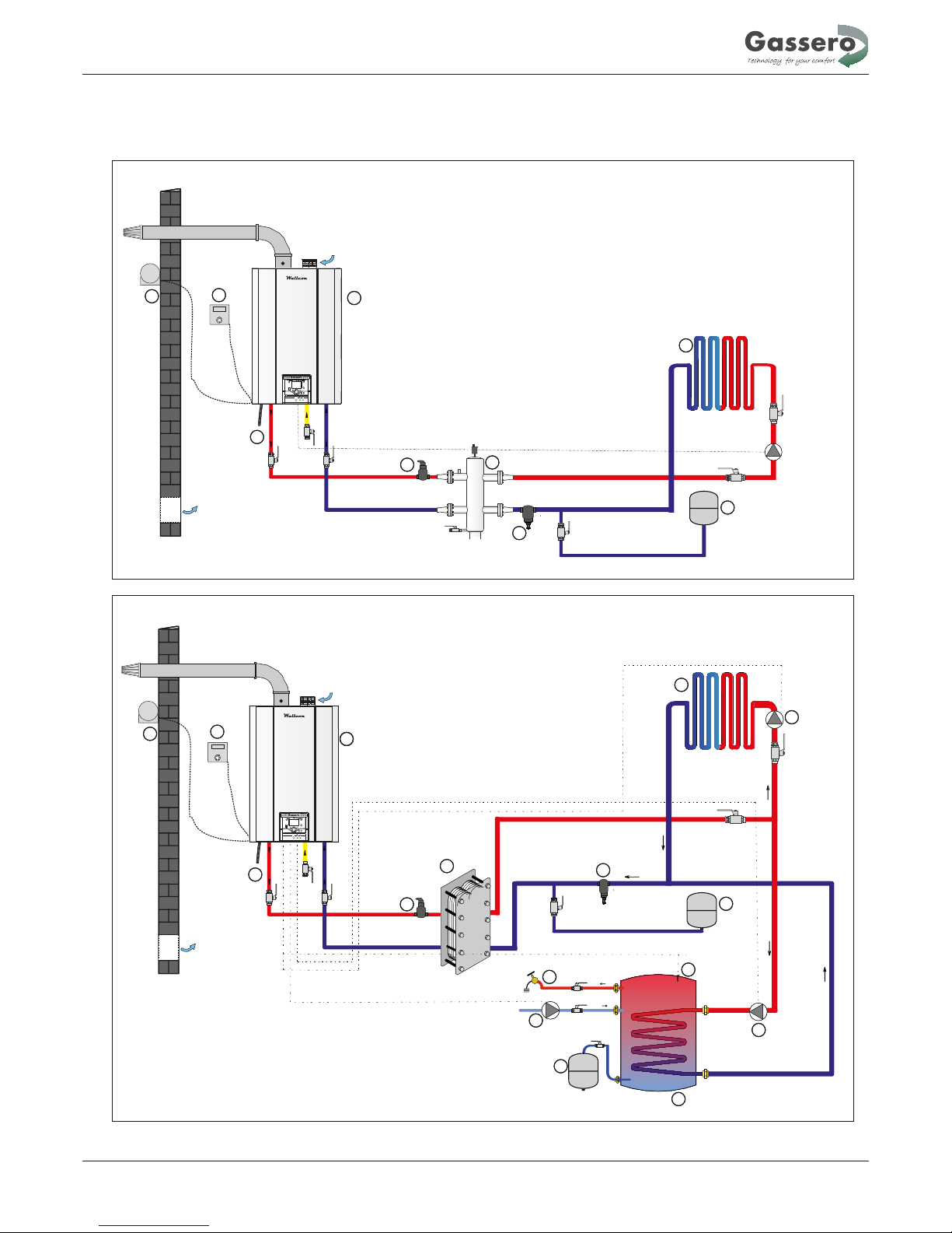
4.2 BOILER INSTALLATION SYSTEM EXAMPLES
4.2.1 SINGLE BOILER INSTALLATIONS
Instructions for the installer
14
4
1
3
5
7
6
8
10
2
4
3
7
8
9
10
11
12
16
15
14
13
11
2
5
6
RESET
RESET
Page 16
Instructions for the installer
15
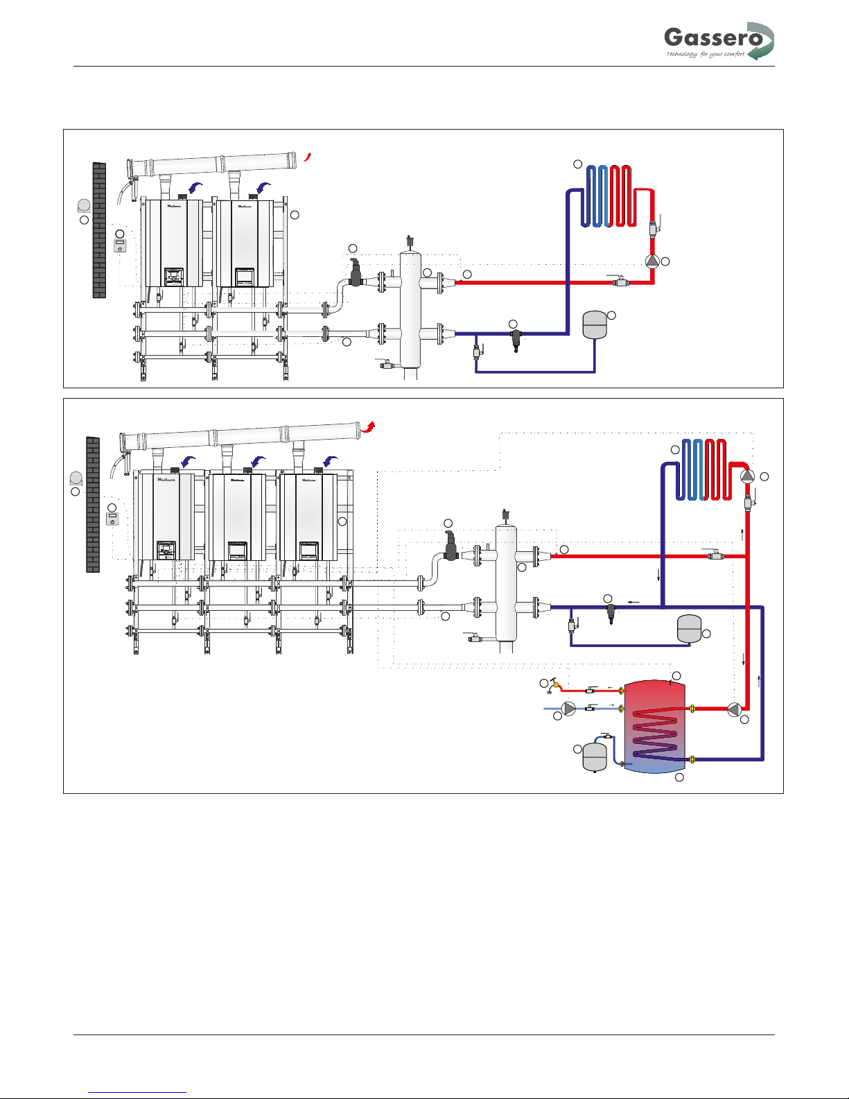
4.2.2 CASCADE INSTALLATIONS
1 - Wallcon condensing boiler
2 - Room thermostat (QAA55)
3 - Outside probe (QAC34)
4 - Condansate discharge
5 - Air seperator
6 - Plate heat exchanger / Low loss header
7 - Dirt seperator
8 - Expansion vessel
9 - Radiator pump
10 - Heating system(radiator/underfloor)
11 - DHW tank pump
12 - DHW tank sensor (QAZ36)
13 - Hot water
14 - DHW re-circulation pump
15 - DHW tank expansion vessel
16 - DHW tank
17 - Cascade supply sensor (QAD36)
18 - Cascade return sensor (QAD36)
Key
Air Intake
Fume discharge
3
2
1
5
6
7
17
18
8
9
10
Air Intake
Fume discharge
3
2
1
5
6
18
13
17
7
9
10
8
11
14
15
12
16
RESET
RESET
SLAVE
RESET
SLAVE
RESET
SLAVE
RESET
SLAVE
Page 17
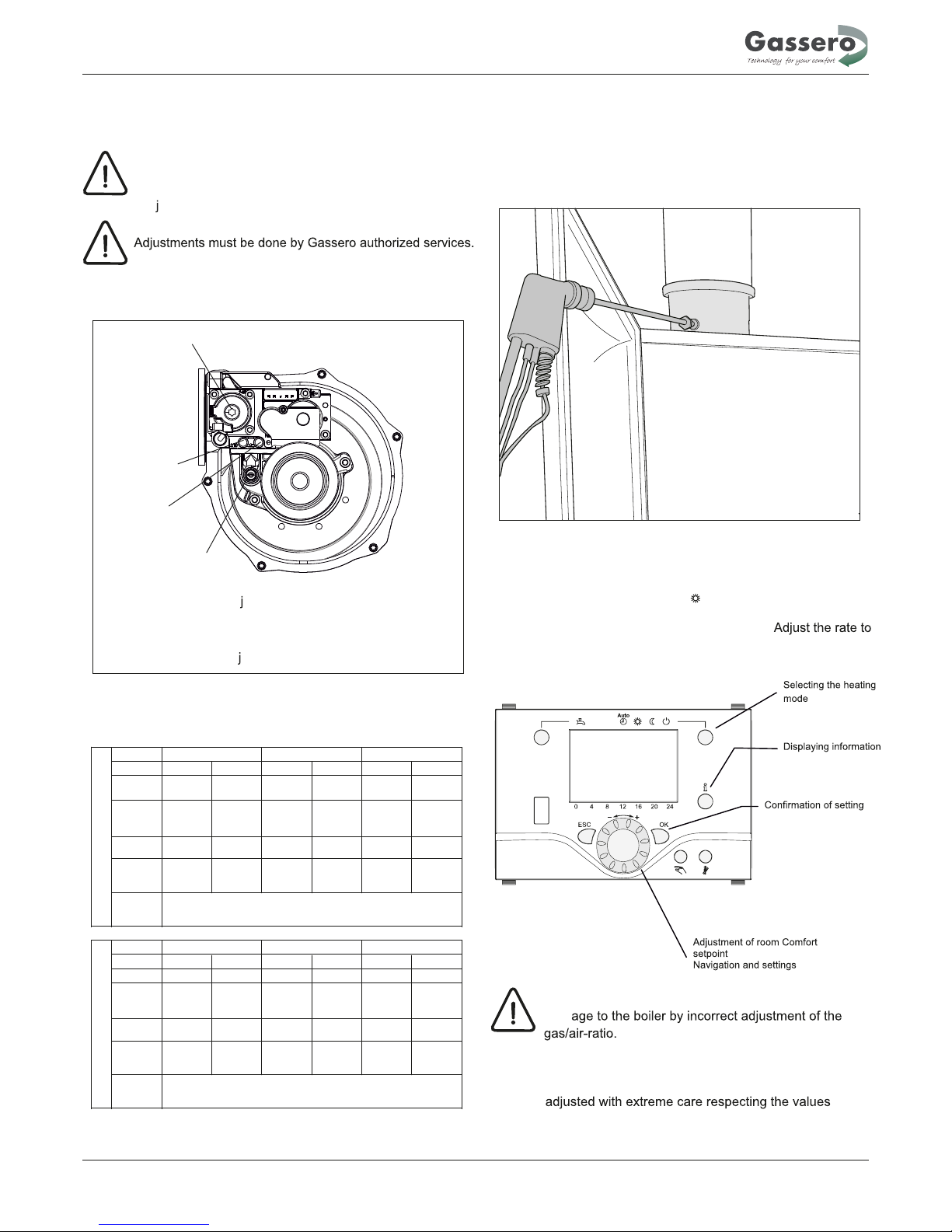
4.3 ADJUSTMENT OF THE GAS RATE
All the instructions written below are for the exclusive
use of qualified service technicians or installers. All the
boilers are supplied already calibrated and tested.
Ad
ustments are only be made with special tools.
4.3.1 Description of the adjustment points
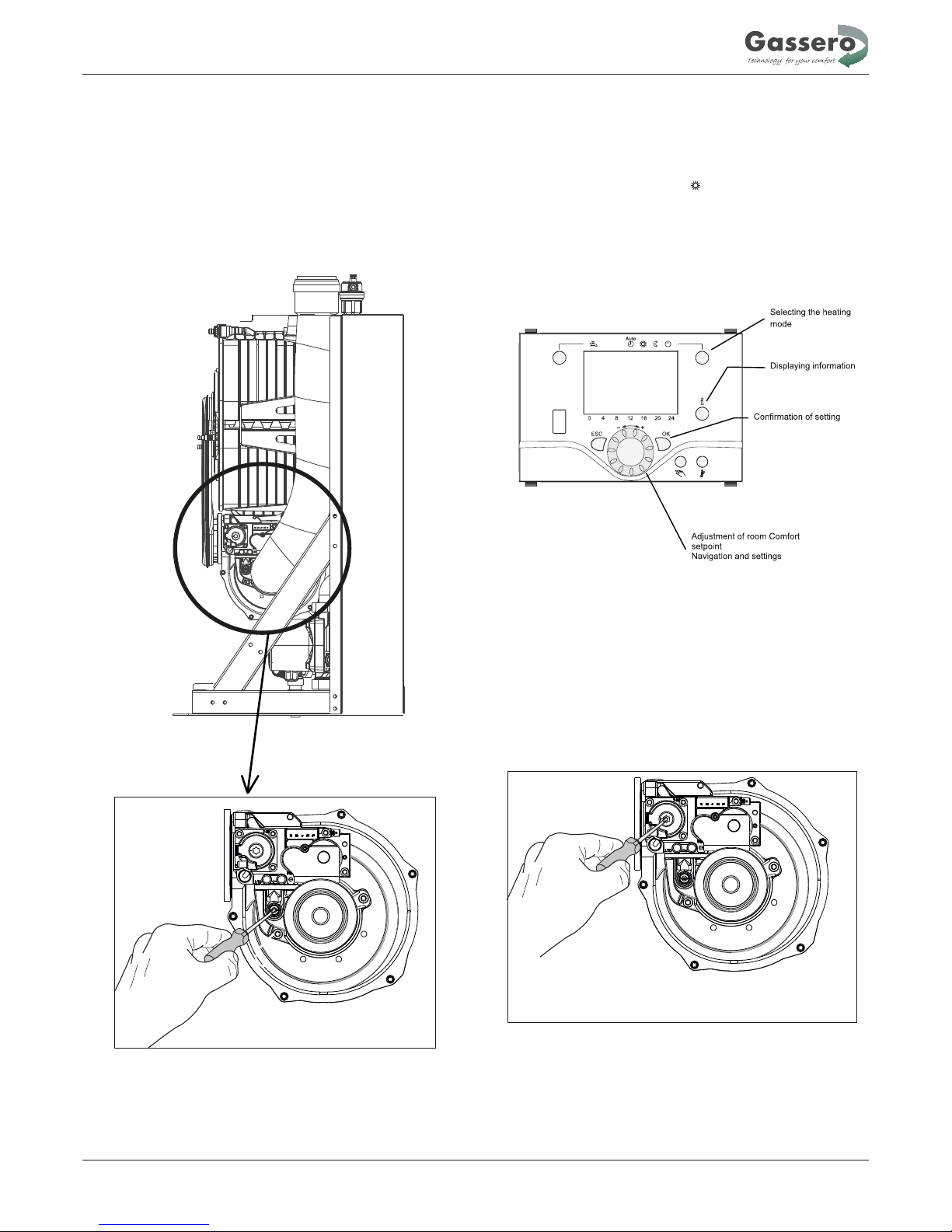
A - Maximum output ad ustment screw
B - Outlet pressure tap
C - Inlet pressure tap
D - Minimum output ad
ustment screw
4.3.2 Combustion values adjustment table
4.3.3 Maximum output adjustment
1 - Connect the gas analyser probe to the sampling test point
on the flue adapter.
2
WARNING:
Dam
To ensure correct operation the values have to be
indicated in the table.
- For operating in the max. output, press at least 3 seconds to
heating mode when the boiler in mode.Controller function stop
will appear on the screen.Than press information button, it will
indicate the modulation rate (%) on the screen.
100% for max. output setting with using of navigation button. Then
press OK . Thus, boiler will operate in maximum power.
Instructions for the installer
16
100 %
B
D
A
C
Model
Q min. max. min. max. min. max.
CO2 %
8,9 9,2 8,9 9,2 8,9 9,2
Gas Flow
Rate
(m
3
/h)
0,9 4,2 0,9 5,1 1,57 6,7
Fan Speed
(rpm)
1250 5100 1250 6000 1700 6500
Flue Gas
Mass
(g/sec.)
3,7 17,7 3,7 21,6 6,9 28,4
Nozzle
Diameter
(mm)
Model
Q min. max. min. max. min. max.
CO2 %
8,9 9,4 8,9 9,4 8,9 9,2
Gas Flow
Rate
(m
3
/h)
1,0 4,80 1,0 5,9 1,82 7,8
Fan Speed
(rpm)
1300 5100 1300 6250 1700 6500
Flue Gas
Mass
(g/sec.)
3,7 17,4 3,7 21,3 7 28,4
Nozzle
Diameter
(mm)
Wal lcon 42 Wallcon 50 Wallcon 67
G20
7,7
G25
Wal lcon 42 Wallcon 50 Wallcon 67
9,5
Page 18
3 - Connect the pressure gauge connection tube to inlet and
outlet pressure tap and check the pressures. Inlet/Outlet
pressures must be adjust according to the table. Check
the CO values are within the values indicated in the table.
2
Correct the value by turning the adjustment screw (A) in
clockwise direction to decrease the value and in an anticlockwise direction in order to increase the value.
4.3.4 Minimum output adjustment
2 - Check the values at the minimum output.CO
2
Make the required adjustments if necessary. valuesCO
2
have to be adjusted with extreme care respecting the values
indicated in the table. Correct the value by turning the adjustment
screw (D) in clockwise direction to increase the value and in
anti-clockwise direction in order to decrease the value. When the
adjustments have done,
close sampling test point in the flue adapter
with the cap.
Instructions for the installer
17
1
- For operating in the min. output, press at least 3 seconds to
heating mode when the boiler in mode.Controller function stop
will appear on the screen.Than press information button, it will
indicate the modulation rate (%) on the screen. Adjust the rate to
0% for min. output setting with using of navigation button. Then
press OK . Thus, boiler will operate in minimum power.
0 %
Page 19
Instructions for the installer
18
4.4 GAS CONVERSION INSTRUCTIONS
All the instructions written below are for the exclusive
use of qualified service technicians or installers.
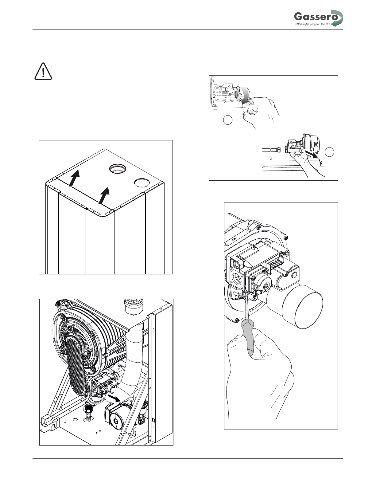
1 - Close the gas valve and gas supply pipe to the boiler.
2 - Remove the front cover of the boiler.
The unit can operate on natural gas or LPG and is factory-set for
use with one of these two gases, as clearly shown on the packing
and on the dataplate. If a gas different from that for which the unit
is arranged has to be used, a conversion kit will be required,
proceeding as follows:
3 - Remove the air intake pipe from venturi adapter.
4 - Remove the gas supply pipe from gas valve.
1
2
5 - Disconnect the gas valve from venturi by removing screws.
Page 20
Instructions for the installer
19
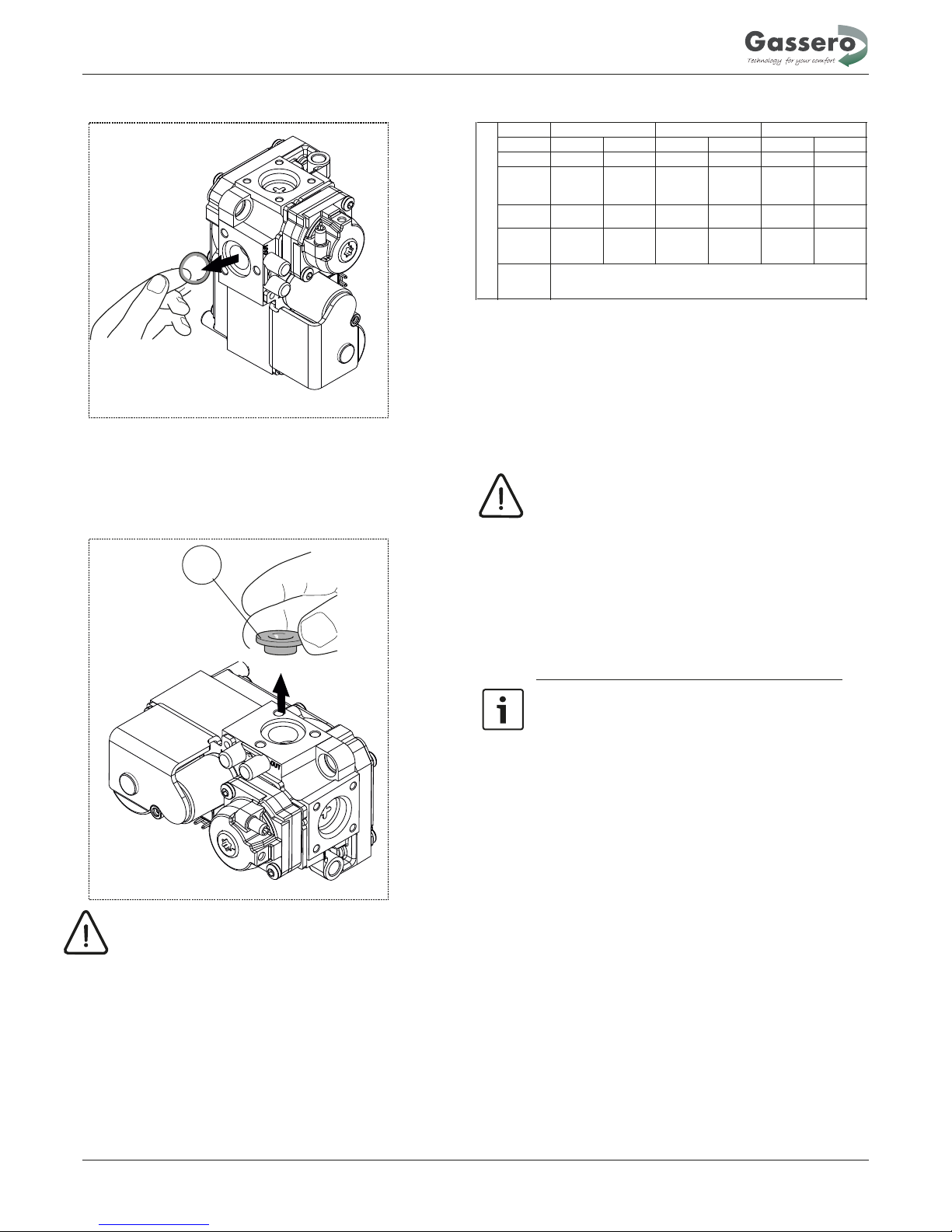
6 - Remove the o-ring from gas valve.
nozzle
7 - Remove the current gas nozzle than install the right gas
nozzle including the enclosed O-ring for the type of gas
supply.
G20 nozzle diameter : 7.7 mm
G25 nozzle diameter : 9.5 mm
G30 butane/G31 propane nozzle diameter : 5.5 mm
***Lower calorific powers at 15°C, 1013mbar:
3
N.Gas G20 : Hi = 34,02 MJ/m
3
N.Gas G25 : Hi = 29,25 MJ/m
3
Butane G30 : Hi = 116,09 MJ/m
3
Propane G31 : Hi = 88,0 MJ/m
WARNING:
Please contact with Gassero services for nozzle types.
Gas conversions must done by authorized qualified
service technicians.
4.5 FLUE INSTALLATION INSTRUCTIONS
The flue and the fitting to the flue must be made in
compliance with the standards and the legislation in
force, as well as with local regulations.
The pipes used must be rigid and resistant to
temperature, condensate and mechanical stress,
and airtight.
Non-insulated flues are potential sources of danger.
IMPORTANT INFORMATION
If the lowest part of the terminal is less than 2 metres above the
level of the ground, balcony, flat roof or place to which any
person has access, the terminal must be protected by a guard.
The flue assembly shall be so placed or shielded as to prevent
ignition or damage to any part of the building. The flue outlet
duct and the terminal of the boiler MUST NOT be closer than
to combustible material.
It is very important to ensure, that products of
combustion discharging from the terminal cannot
re-enter the building or any other adjacent building.
Through ventilators, windows, doors, other sources
of natural air infiltration, or forced ventilation / airconditioning. If this could occur the appliance MUST
be turned off, and signed as unsafe until corrective
action can be taken.
Model
Q min. max. min. max. min.
CO2 %
10,6 11,1 10,6 11,1 10,7
Gas Flow
Rate
(m
3
/h)
0,3 1,2 0,3 1,5 0,47
Fan Speed
(rpm)
1200 4750 1200 5750 1350
Flue Gas
Mass
(g/sec.)
3,5 16,6 3,5 20,2
Nozzle
Diameter
(mm)
G30
Wal lcon 42 Wal lcon 50
5,5
max.
11,1
2,0
5900
6,5 26,5
Wal lcon 67
Page 21
Instructions for the installer
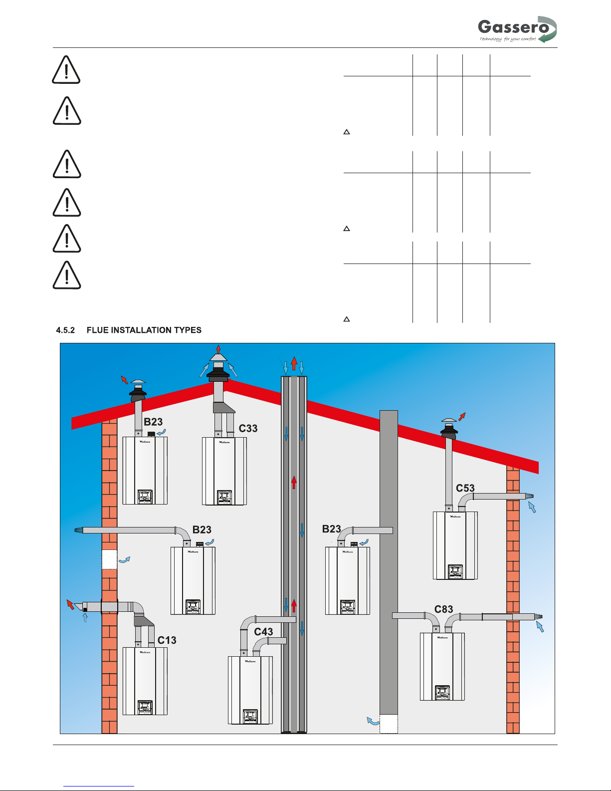
C =53 Two ducts connected to the corresponding air intake
and fume discharge terminals in different pressure
zones.
C =63 Air intake and fume discharge ducts and/or terminals
are not delivered by the manufacturers and supplied
with their own certificates.
C =83 Ducts to be connected to a terminal and independent
or shared flue by means an adapter.
Note: The terminal for the supply of combustion air
and for the evacuation of combustion products shall
not be installed on opposite walls of the building.
Note: The boiler shall only be installed with a terminal
that complies with the requirements of EN 1856-1
(see Annex N).
20
4.5.1 FLUE APPLIANCE TYPES
B =23
The combustion
air is intaken directly from the room where the
boiler is installed.
Smoke evacuation duct connected to outside from
room where the boiler is installed.
C =13 Concentric and closely placed ducts connected to
a horizontal terminal for fresh air intake and fume
discharge.
C =33 Concentric and closely placed ducts connected to
a vertical terminal for fresh air intake and fume
discharge.
C =43 Two connecting ducts and two collecting flue ;
one for fresh air intake and other one is for fume
discharge.
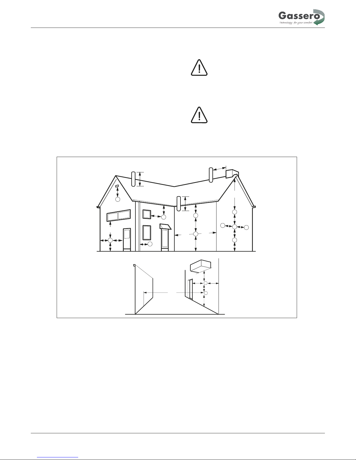
Terminal position Minimum spacing:
A Directly below, above or alongside an opening window, air vent or other ventilation opening 300 mm
B Below guttering, drain pipes or soil pipes 200 mm
C Below eaves 200 mm
D Below balconies or a car port roof Not recommended! 200 mm
E From vertical drain pipes or soil pipes 150 mm
F From internal or external corners 300 mm
G Above adjacent ground, roof or balcony level 300 mm
H From a surface facing the terminal 600 mm
I From a terminal facing a terminal 1200 mm
J From an opening in a car port (e.g. door or window) into dwelling. Not recommended! 1200 mm
K Vertically from a terminal on the same wall 1500 mm
L Horizontally from a terminal on the wall 300 mm
M Adjacent to opening 300 mm
N Above intersection with roof 300 mm
O From a vertical structure on the roof 500 mm
A
F
M
G
M
B,C
F
F
B,C
K
G
K
K
G
C
L
L
A
N
N
O
E
FJ
K
G
D
H, I
Sitting the flue terminals
Page 22
Instructions for the installer
Wallcon 42
B23 C13 C33
C43,C53
C63,C83
Air intake dia.(mm)
Flue duct dia.(mm)
Max. length (m)
p at Max. Qn (Pa)
80
80
30
100
125
80
2
125
80
2
80
80
30
100100 100
Only use original GASSERO flue gas discharging
systems.
Flue installations must be done by authorized person.
Flue installations must be done according to local
ventilation requirements.
21
RESET
RESET
RESET
RESET
RESET
RESET
RESET
RESET
It is important that the position of the terminal allows
the free passage of air at all times.
The air supply and the flue gas exhaust must meet the
applicable general regulations. Please consult the
instructions provided with the flue terminal kits prior to
installation.
The flue for installations in excess of 67 kW must be
installed in accordance with the recommendations of
IGE UP10.
Wallcon 50
B23 C13 C33
C43,C53
C63,C83
Air intake dia.(mm)
Flue duct dia.(mm)
Max. length (m)
p at Max. Qn (Pa)
80
80
30
140
125
80
2
125
80
2
80
80
30
140140 140
Wallcon 67
B23 C13 C33
C43,C53
C63,C83
Air intake dia.(mm)
Flue duct dia.(mm)
Max. length (m)
p at Max. Qn (Pa)
80
80
25
170
125
80
2
125
80
2
80
80
25
170170 150
Page 23
Instructions for the installer
22
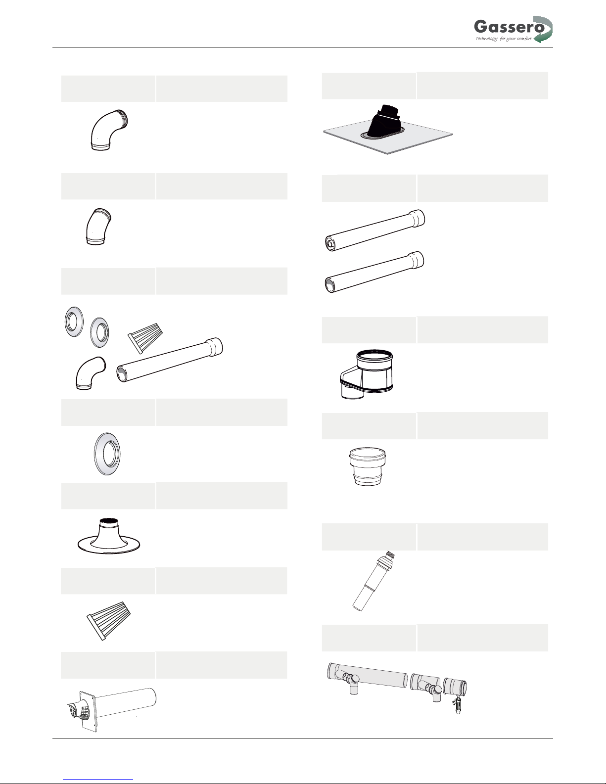
4.5.3 FLUE KIT ACCESORIES
Accesory Description
Code : 746600761
Accesory Description
Code : 746600763
Accesory Description
Code : 746600765
Code : 746600762
Code : 746600764
Accesory Description
Code : 746600767
Flat weather collar
Accesory Description
Code : 746600770
Pitched weather collar
Accesory Description
Code : 746600771
Code : 746600772
Accesory Description
Code : 746600775
Accesory Description
Code : 746600768
Bird guard
Accesory Description
Code : 746600777 (*)
Accesory Description
Code : 746600766
B23 flue kit (1m)
Accesory Description
Code : 746600773
Cascade flue kit
(*) This flue kit is for two-boiler cascade system.For larger cascades
please contact your Gassero dealer.
o
87 coaxial elbow
o
87 elbow
o
45 coaxial elbow
o
45 elbow
Wall rosette
Coaxial extension
Extension
Coaxial adapter
Air intake adapter
for twin flue
Accesory Description
Code : 746600769
Horizontal flue terminal
Accesory Description
Code : 746600776
Vertical flue terminal
Ø 80/125
Ø 80
Ø 80/125
Ø 80
Ø 80
Ø 80
Ø 80/125
Ø 80/125
Ø 80
Ø 80/80 - Ø 80/125
Ø 60-80
Ø 80/125
Page 24
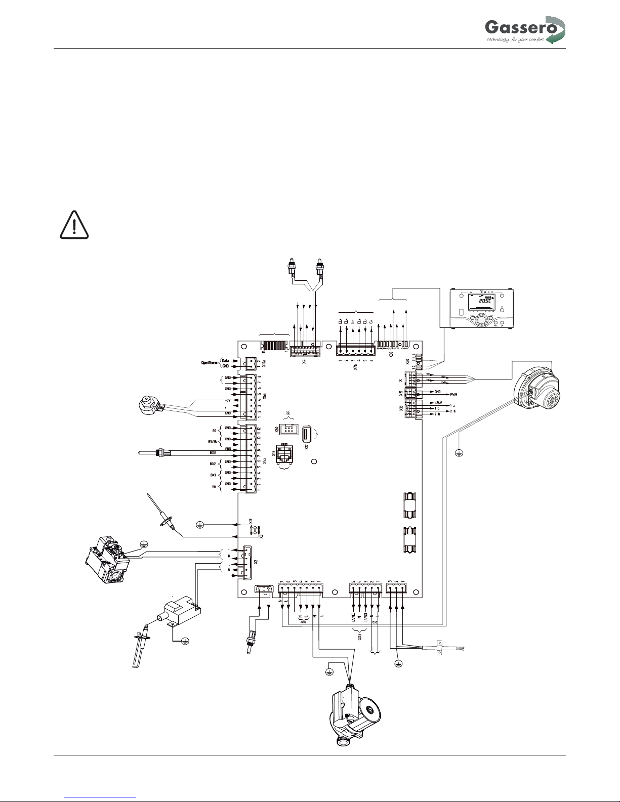
4.6.1 WIRING DIAGRAM
Instructions for the installer
23
LED flame
LED lockout
Reset
+12 V
CL+
GND
Fan PWM
IGNITION TRANSFORMER
OCI430
AGU2.56...
BSB bus room unit
Room temperature
4 5
3
2
1
X17 EARTH
4 3
2
1
8
6.3 A
6.3 A
FUSE FUSE
X1a
X1b
230V~50Hz
X18
Thermalfus e
X1f
PUMP
PENL
X17
EARTH
X17 EARTH
Return Water Temperature
NTC Sensor
Flow Water Temperature
NTC Sensor
Cascade Module
GAS VALVE
FLUE GAS
TEMPERATURE SENSOR
PRESSURE
TRANSDUCER
IGNITION
ELECTRODE
IONISATION
ELECTRODE
External Probe
Boiler sensor
Cascade sensor
X17 EARTH
X17
EARTH
Room Thermostat
X17 EARTH
4.6 ELECTRICAL INSTALLATION
All the wiring is connected to connectors that is fitted in a socket. The connectors can be taken from the sockets on the PCB without
loosening the wiring. The connections are placed in the back of the display, and can be reach by removing the front panel of the boiler
and the connector protection cover. For operation the boiler needs a power supply of 230VAC 50Hz with earth.Power supply must be
removed when you are working on the boiler. Electrical wiring should be done according to national, local or other special standards.
Electrical works must be done by a qualified service engineer that is skilled in electrical installation according to the standards.
1 - Respect the connection L (Line) - N (Neutral) and earth (ground) connections.
2
2 - Use wires with a cross-section greater than or equal to 1.5 mm , complete with pointed end terminals;
3 - Refer to the wiring diagrams in this manual for any operations on the electrical system;
4 - Connect the appliance to an effective earth system.
5 - Power supply and room thermostat cables must not run near hot surfaces (outlet pipes).
The manufacturer is not liable for any damage due to
the failure to earth the appliance and to observe the
information provided on the wiring diagrams.
CH PUMP
Page 25
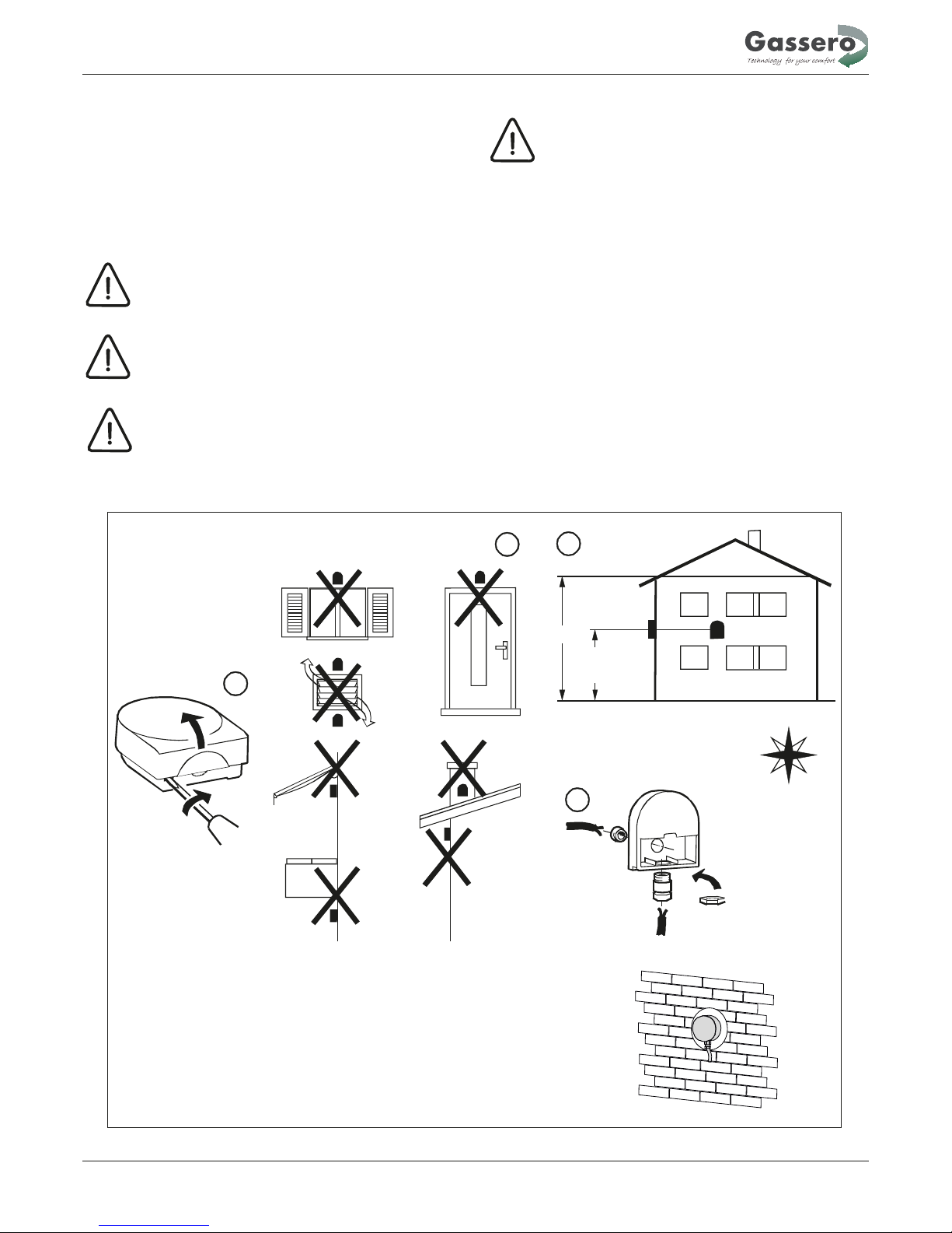
4.6.2 EXTERNAL PROBE INSTALLATION
The probe should be placed on a smooth section of
the wall; in the event of exposed brick walls or une ven walls, a smooth contact area should be used.
The maximum length of the connection between
the outside probe and the control panel is 50 m.
*Temperature measured T 25°C
*Resistance of the probes R 1000 Ω
The connection cable between the probe and control panel must not have junctions; if required, these
must be sealed and adequately protected.
Any conduits used for the connection cable must
be separate from the power cables (230V).
H
H
2
/
1
N
N-W
3
min2,5 m
1
2
4
Instructions for the installer
24
The correct positioning of the outside probe is fundamental for
the correct operation of the climate control function.The probe
must be installed outside of the building being heated, at a
height of around 1/2 of the wall facing NORTH or NORTH-WEST
and away from flues, doors, windows and areas exposed to
direct sunlight.
Fastening the outside probe to the wall
- Unscrew the cover on the probe protection box, turning
it anticlockwise to access the terminal block and the
fastening holes
- Trace the fastening points using the protection box as
the template
- Remove the box and drill the holes for the expansion
plugs
- Fasten the box to the wall using the two plugs supplied
- Connect the two wires on the cable to the ter minal
block, without needing to identify the polarity
- Tighten the nut on the cable gland and close the cover
on the protection box.
Page 26
Instructions for the installer
25
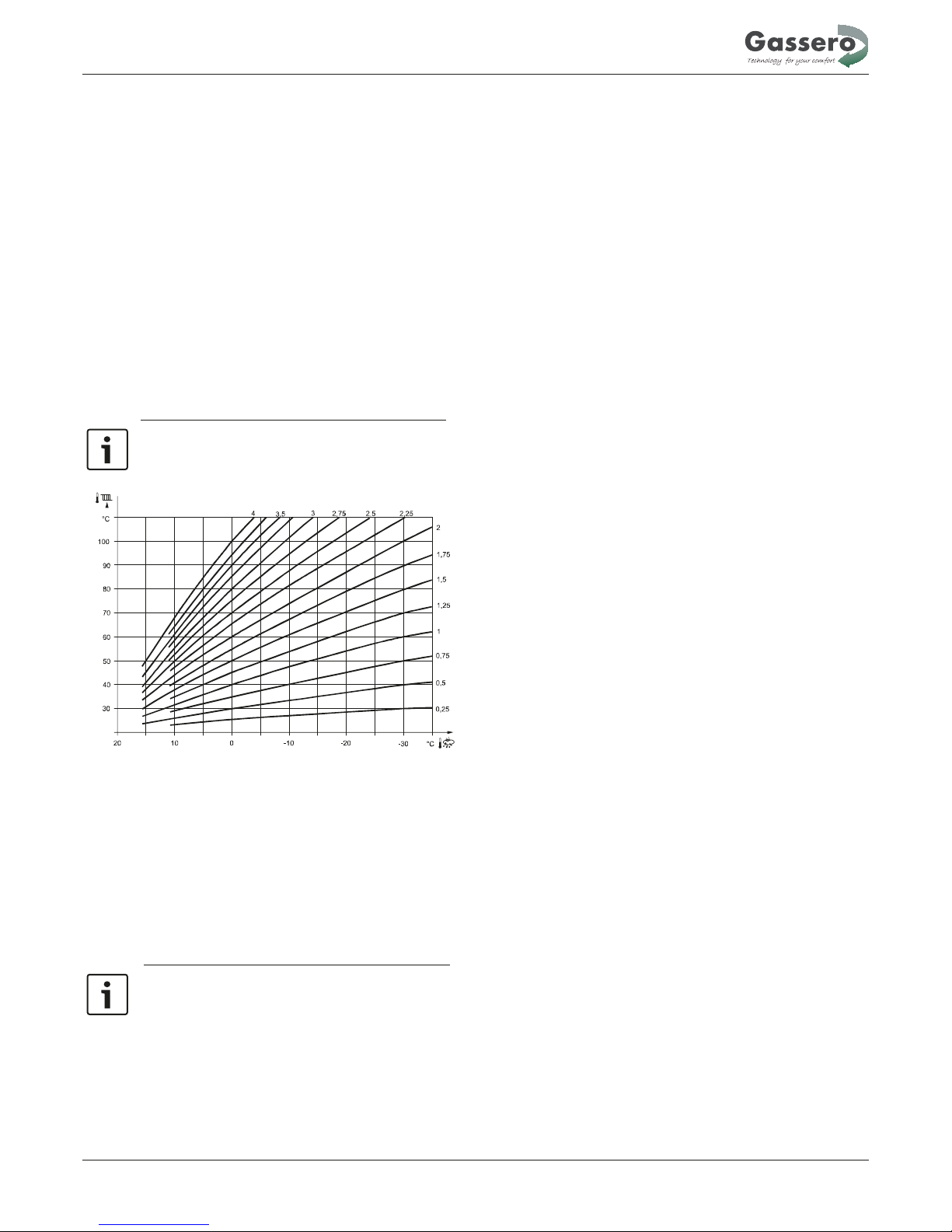
4.6.3 OUTDOOR TEMPERATURE CONTROL ( OTC )
The heating curve generates the flow temperature setpoint,
which is used to maintain a certain flow temperature level
depending on the prevailing weather conditions. The heating
curve can be adjusted in different ways, thus matching the heat
output and the room temperature to individual needs. When the
heating curve slope is raised, the flow temperature increases
as the outside temperature drops. Or, in other words, if the
room temperature is not correct at low outside temperatures
but correct at higher outside temperatures, the heating curve
slope must be readjusted.
Increasing the slope: Raises the flow temperature, especially
when the outside temperature is low.
Decreasing the slope: Lowers the flow temperature, especially
when the outside temperature is low.
IMPORTANT INFORMATION
The set heating curve is based on a room temperature
setpoint of 20 °C. If this setpoint is changed, the
heating curve adapts automatically to the new value.
Heating curve – heating curve slope
Outdoor temperature
Flow temperature
Parallel displacement of the heating curve is used to change the
flow temperature evenly across the entire outside temperature
range or, in other words, if the room temperature is always too
high or too low, a readjustment must be made with parallel
displacement. Adaption of the heating curve is used by the
controller to automatically adapt the heating curve to the
prevailing weather conditions. In that case, a readjustment of
heating curve slope and parallel displacement is not required.
It can only be switched on or off.
IMPORTANT INFORMATION
To provide this function, following must be observed:
• A room sensor must be connected
• The Room influence setting must be selected between
1 and 99
• No thermostatic radiator valves should be used in the
reference room, where the room sensor is located (if
installed, such valves must be fully opened and locked
in that position)
The function is activated with parameter, provided a room sensor
is used and the compensation variant is weather compensation
with room influence. If the required flow temperature is exceeded
or is not reached for more than 2 hours, no adaption is made for
that day. With pump heating circuits, the boiler temperature is
used in place of the flow temperature. Heating curve adaption
readjusts the heating curve’s slope and the parallel displacement
(heat gains). In Comfort mode (nominal operating level), the
function integrates the room temperature control deviation and
readjusts at midnight the parameters for calculating the heating
curve, depending on the attenuated outside temperature and the
learning sensitivity. During boost heating, the deviation of room
temperature control is not taken into consideration. When
readjusting the heating curve or the heat gains, the
sensitivity is automatically set to the maximum. A certain
minimum sensitivity is always maintained. If the attenuated
outside temperature is below 4 °C, the heating curve slope is
readjusted through the learning process. If the attenuated
outside temperature lies between 4 °C and 12 °C, heating curve
slope and parallel displacement are readjusted through learning.
If the attenuated outside temperature exceeds 12 °C, the
learning process is stopped. These basic values apply to a
Comfort setpoint of 20 °C, heat gains of 0 K and a heating curve
displacement of 0 K.
Page 27
5 OPERATION
The WALLCON boilers are fitted with SIEMENS control unit as
standart. This controller can be used to control of heating system,
with 3 different zones and building automatization.
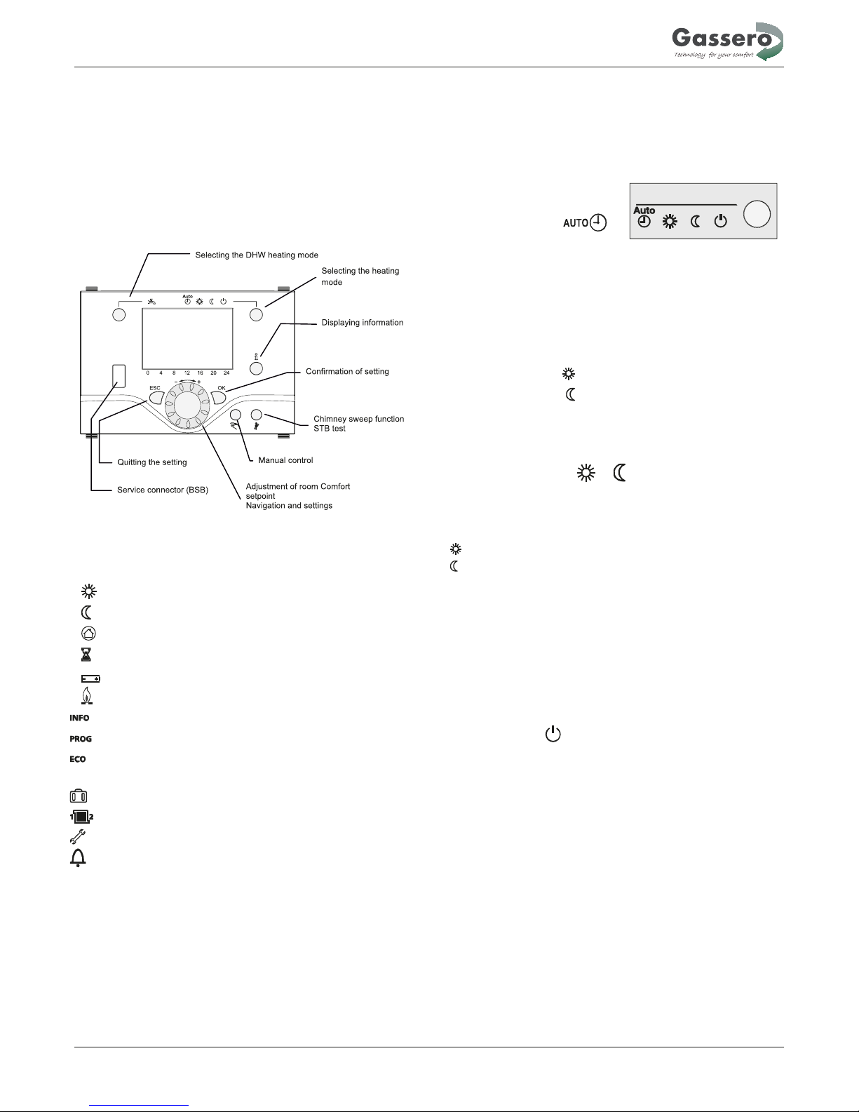
The boiler controller consists of the following
components:
Display choices
Heating to the Comfort setpoint
Info level activated
Heating to the Reduced setpoint
Programming activated
Heating to the frost protection setpoint
ECO function active
Heating system temporarily off
Process running – please wait
Holiday function active
Change battery
Reference to heating circuit
Burner in operation (only oil / gas burner)
Maintenance / special mode
Error messages
Selection of space heating mode
Press the button to switch between the different operating
The choice made is indicated by a bar which appears below the
symbols.
Automatic operation
Automatic operation controls the room temperature
Charactersitics of automatic operation:
− Heating mode according to the time program
− Temperature setpoints according to heating program
“Reduced setpoint“
Protective functions active
− Automatic summer / winter changeover (ECO functions)
Continuous operation
or
Continuous operation maintains the room temperature
Heating to the Comfort setpoint
Heating to the Reduced setpoint
Characteristics of continuous operation:
• Heating mode with no time program
• Protective functions active
• Summer/winter heating limit and automatic
During continuous operation with comfort setpoint:not active
During continuous operation with reduced setpoint: Active
Protective mode
When using Protection, the heating system is off.
temperature), provided there is no power failure.
according to the time program.
“Comfort setpoint“
or
at the selected operating level.
24-hour heating limit (ECO functions)
But it remains protected against frost(frost protection
Characteristics of Protection:
• Heating off
• Temperature according to frost protection
• Protective functions active
• Automatic summer / winter changeover (ECO functions)
and automatic 24-hour heating limit active
Operation
26
5.1 GENERAL
−
Page 28
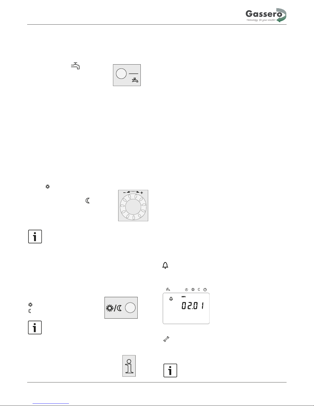
Selecting DHW heating
The button is used to switch DHW heating mode on and off.
The choice made is indicated by a bar which appears below
DHW heating mode
•
On
The DHW is heated according to the selected switching
•
Off
No DHW heating, but the protective function is active.
DHW push
To do this, keep the DHW operating mode button on the
operator or room unit depressed for at least 3 seconds.
The DHW push can also be started when:
• The operating mode is “Off“
• Operating mode changeover acts via H1 or centrally
• All heating circuits have assumed the holiday mode
the symbols.
program.
Adjusting the room temperature setpoint
Turn the setting knob to increase or decrease the
Comfort
setpoint
.
For the Reduced setpoint
−
Press the OK button
− Select operating page “Heating circuit“ and
− Adjust the “Reduced“ setpoint
Each time you make a readjustment, wait at least 2
hours, allowing the room temperature to adapt.
Presence button
If the rooms are not used for a certain period of time, you can
press the occupancy button to reduce the room temperature,
thus saving heating energy.
When the rooms are occupied again, press again the occupancy
button to resume heating operation.
Heating to the Comfort setpoint
Heating to the Reduced setpoint
•
The occupancy button is only active in
• The current selection is active until the next switching
action according to the heating program occurs.
automatic operation
Displaying information
The Info button is used to display information.
Certain information lines are hidden, depending on the type of
unit, unit configuration and operating state.
Depending on the type of unit, configuration and operating
state, some of the info lines listed below may not appear.
Displays:
- Possible error messages from the error code are listed in the
- Possible maintenance alarms from the maintenance code are
- Possible special mode messages
Other displays:
− Room temperature
− State DHW
− Room temperature minimum
− State boiler
− Room temperature maximum
− State solar
− Boiler temp
− State solid fuel boiler
− Outside temperature
− State buffer storage tank
− Outside temp min
− Date and time of day
− Outside temp max
− Telephone customer service
− DHW temp 1
− State heating circuit 1
− State heating circuit 2
− State heating circuit P
In exceptional cases, display shows one of the following
Error messages
If this symbol appears, a plant fault occurred. In that case,
press the Info button to obtain more information.
Text3 Text4
0
4 8 12 16 20 24
AUTO
30:Flow sensor 1
Error
Maintenance or special mode
If this symbol appears, a maintenance alarm is delivered
or the plant has changed to special mode. In that case,
press the Info button to obtain more information.
Available information
Possible displays:
Exceptional cases
manual.
isted in the manual.
symbols.
A list of possible displays is given in the manual.
Operation
27
Page 29
Reset function
The reset function for meters and the resettable parameters
appears on the bottom line of the display, provided a reset is
permitted on the current operating line (enduser/commissioning
/ heating engineer).
0
4 8 12 16 20 24
Reset ? yes
After activation of the OK button, display shows a flashing “Yes“
0
4 8 12 16 20 24
Reset ?
yes
After confirmation with the OK button, the relevant parameter
When manual control is active, the relays are no longer energized
and deenergized according to the control state, but are set to a
predefined manual operating state depending on their function.
The burner relay energized in manual control can be deenergized
by the electronic temperature controller (TR).
After manual control has been activated, a change to the basic
display must be made. There, the maintenance / special mode
symbol Press the Info button to switch to info
display “Manual mode“, where the setpoint can be adjusted.
The chimney sweep function is activated by a short press
(maximum 3 seconds) on the chimney sweep button. It
produces the operating state required for making flue gas
or parameters will be reset.
Manual Control
appears.
Chimney sweep function
measurements.
SLT test
The SLT test (SLT = safety limit thermostat) is activated
by a long press (longer than 3 seconds) on the chimney
sweep button. The button must be kept depressed during
the entire test.If released, the test will be aborted. The
SLT test is shown on the display.
The test must be made by qualified technicians since
the boiler temperature will be raised above the maximum
limitations.
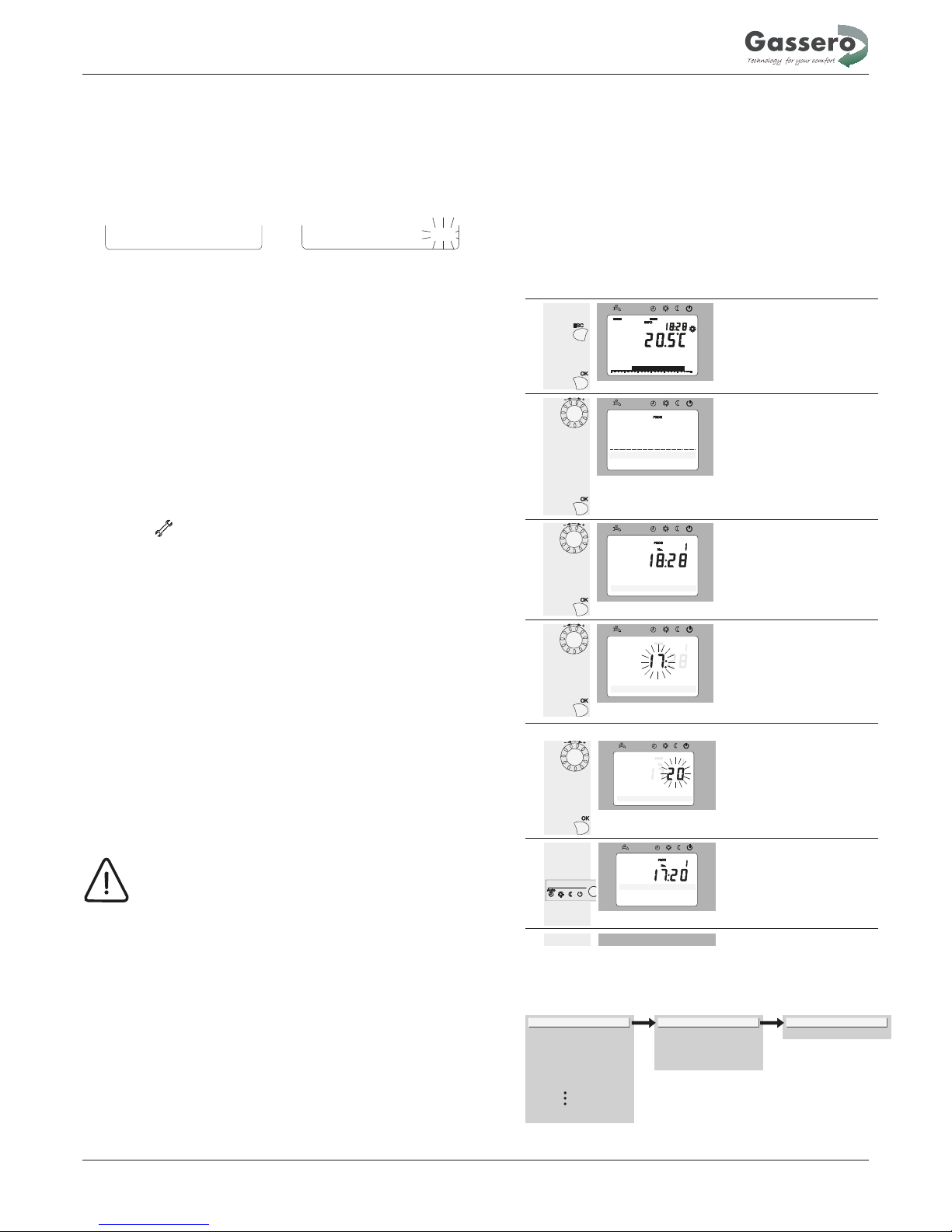
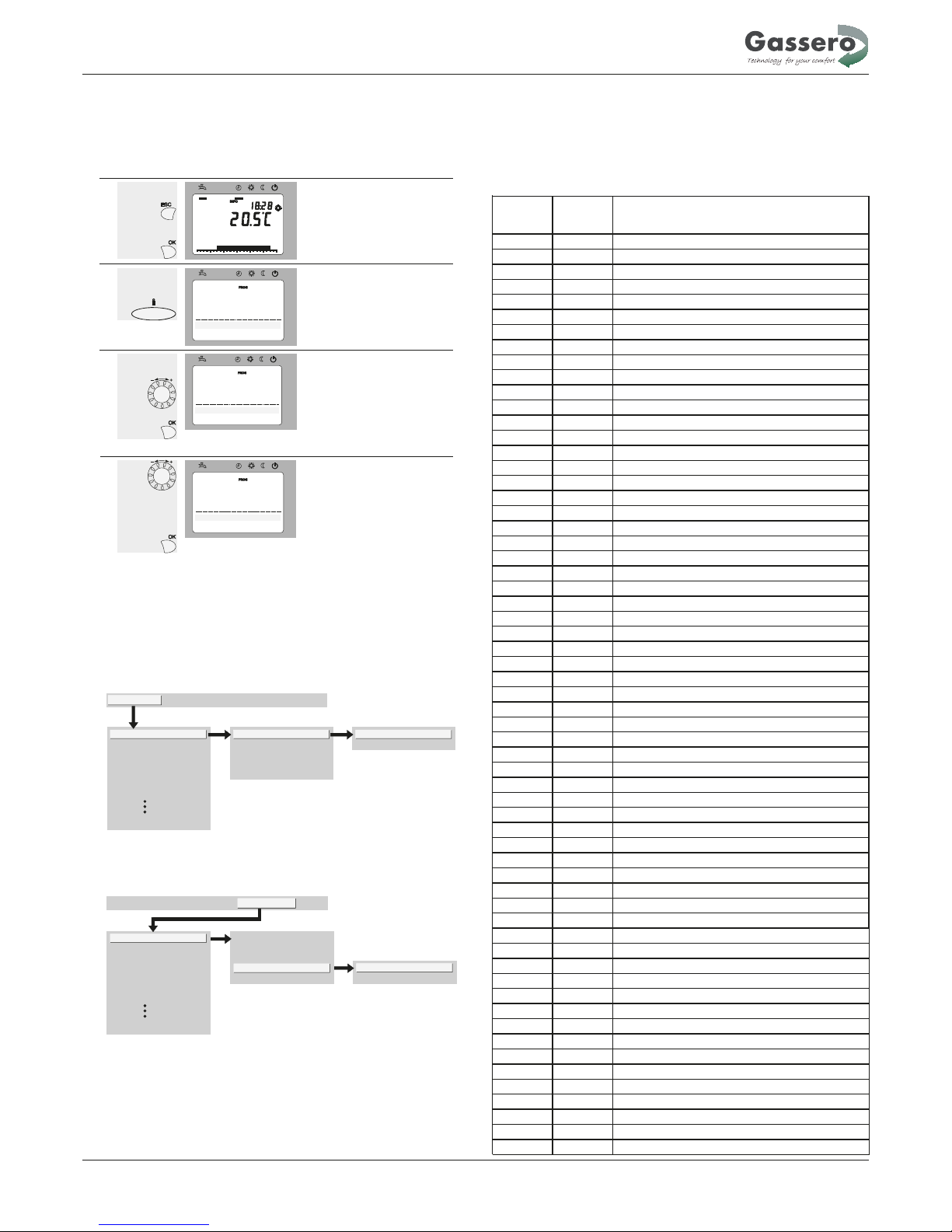
5.2 PROGRAMMING
Setting principle
Settings that cannot be made directly with the help of
operating elements are made through programming.
For this purpose, the individual settings are structured
in the form of operating pages and operating lines,
thus forming practical groups of settings. The following
Example “Setting the time of day“
When pressing the ESC button, you go back one step;
adjusted values will not be adopted
If any setting is made for 8 minutes, the unit will
automatically return to the basic display
•
Operating lines may be hidden, depending on the
type of unit, the configuration and
user level
operation Display example Description
1
0
4 8 12 16 20 24
AUTO
Room temperature
You will see the basic display.
If the basic display is not shown, press
the ESC button to return to it.
Press the OK button.
2
Text3
0
4 8 12 16 20 24
AUTO
Operator section
Time of day and date
The bottom section of the display
shows a number of operating pages.
Turn the setting knob until operating
page “Time of day and date“ appears.
To confirm, press the OK button.
3
0
4 8 12 16 20 24
AUTO
Time of day and date
Hours / minutes
In the bottom section of the display, the
first operating line of operating page
“Time of day and date“ appears.
Turn the setting knob until operating
line “Hours / minutes“ appears.
To confirm, press the OK button.
4
0
4 8 12 16 20 24
AUTO
Time of day and date
Hours / minutes
The display shows the hours flashing.
Turn the setting knob until the hours of
the time of day are correct.
To confirm, press the OK button.
example which shows the setting of the time of day and
date shall explain this.
•
•
5
0
4 8 12 16 20 24
AUTO
Time of day and date
Hours / minutes
The display shows the minutes
flashing.
Turn the setting knob until the minutes
of the time of day are correct.
To confirm, press the OK button.
6
Time of day and date
0
4 8 12 16 20 24
AUTO
Hours / Minutes
The settings are saved, the display
stops flashing.
You can continue to make other
settings, or
you press the operating mode button to
return to the basic display.
7
Now, you have returned to the basic
display.
Time of day and date
Operator section
Wireless
Time program heating circuit 1
Time program heating circuit 2
Time program heating circuit P
Holidays heating circuit 1
Diagnostics of consumers
Hours / minutes
Month / day
Year
Start of summer time
End of summer time
Hours 1...24 h
Minutes 0...60 min
Example of menu structure
Operation
28
Page 30
USER LEVELS
Certain user levels only allow certain user groups to make
settings. To reach the required user level, proceed as follows:
operation Display example Description
1
0
4 8 12 16 20 24
AUTO
Room temperature
You see the basic display.
If the basic display is not shown,
press the ESC button to return to it.
Press the OK button.
2
Text3
0
4 8 12 16 20 24
AUTO
Operator section
Time of day and date
You are on user level “Enduser“.
Press the Info button for 3 seconds.
Text3
0
4 8 12 16 20 24
AUTO
Commissioning
Enduser
You are given a choice of user
levels.
Turn the setting knob until the
required user level is reached.
Press the OK button.
3
4
Text3
0
4 8 12 16 20 24
AUTO
Operator section
Time of day and date
You are now on the required user
level.
To reach the OEM level, enter the relevant code.
Setting structure for “Enduser“
The example given here shows that certain user levels do not allow certain
settings to be made. The example shows them highlighted. On the unit,
OEM
Time of day and date
Operator section
Wireless
Time program heating circuit 1
Time program heating circuit 2
Time program heating circuit P
Holidays heating circuit 1
Diagnostics of consumers
Hours / minutes
Month / day
Year
Start of summer time
End of summer time
Hours 1...24 h
Minutes 0...60 min
Heating engineer
Commissioning
Enduser
Setting structure for ”Heating engineer“
OEMEnduser
Commissioning
Heating engineer
Time of day and date
Operator section
Wireless
Time program heating circuit 1
Time program heating circuit 2
Time program heating circuit P
Holidays heating circuit 1
Diagnostics of consumers
Hours / minutes
Month / day
Year
Start of summer time
End of summer time
Hours 1...24 h
Minutes 0...60 min
they are hidden.
The boiler control unit supports a 16-bit error code. Older
types of operator units might display 8-bit error codes. If
different from the 16-bit error code, the corresponding 8-bit
error code is indicated in parentheses.
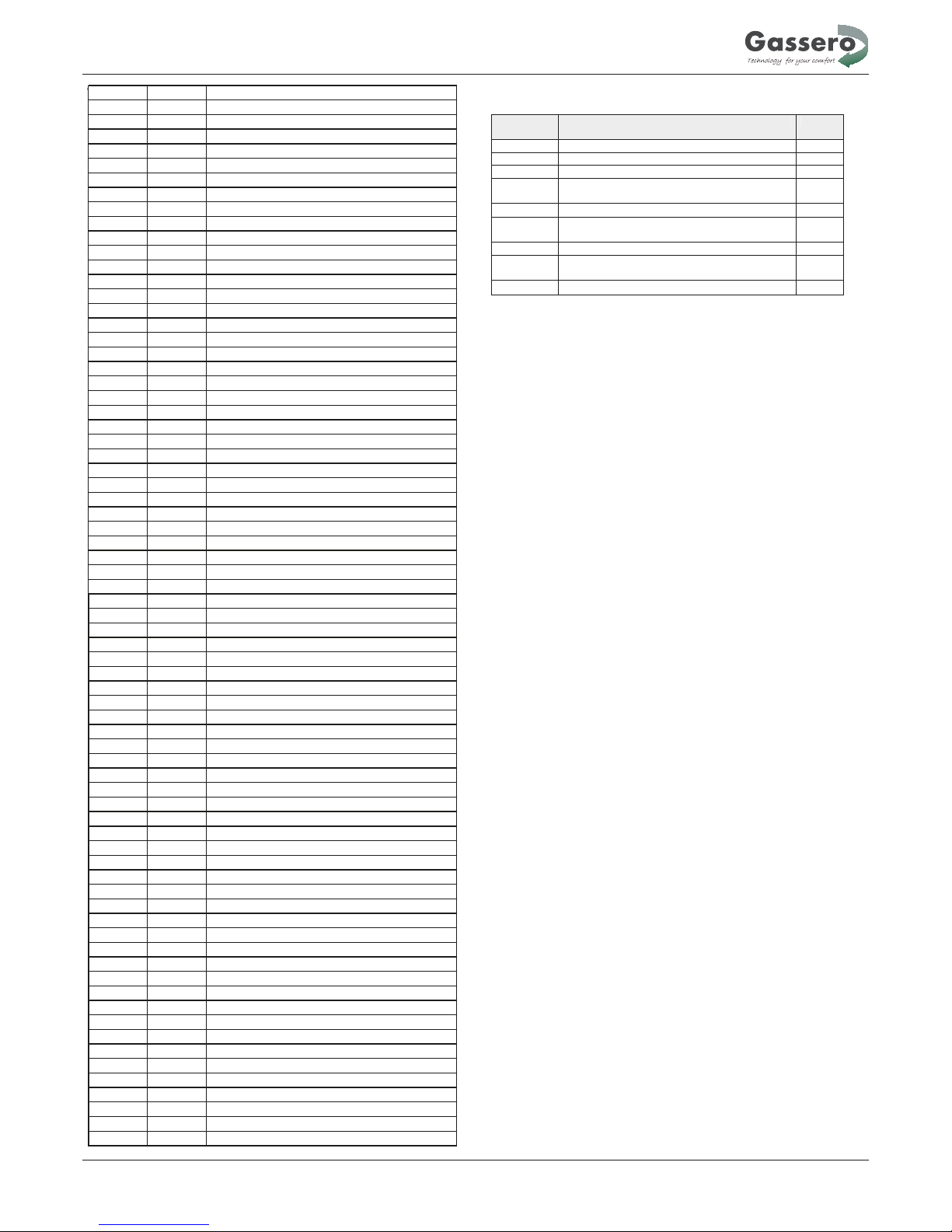
Error Code LPB code Description of error code
10 Outside temperature, sensor error
20 Boiler temperature 1, sensor error
25 Boiler temperature, solid fuel, sensor error
26 Common flow temperature, sensor error
28 Flue gas temperature, sensor error
30 Flow temperature 1, sensor error
38 Flow temperature, prim
ary controller, sensor error
40 Return temperature 1, sensor error
46 Cascade return temperature, sensor error
47 Common return temperature, sensor error
50 DHW temperature 1 sensor error
52 DHW temperature 2 sensor error
54 Flow temperature DHW, sensor error
57 DHW, circulation sensor e rror
60 Room temperature 1, sensor error
65 Room temperature 2, sensor error
68 Room temperature 3, sensor error
70 Storage tank temperature 1 (top), sensor error
71 Storage tank temperature 2 (bottom), sensor error
72 Storage tank temperature 3 (center), sensor error
73 Collector temperature 1, sensor error
78 Water pressure, sensor error
82 LPB address collision
83 BSB wire cross-sectional/no communication
84 BSB wire address collision
85 BSB RF communication error
91 Data overrun in EEPROM
98 Extension module 1, error
99 Extension module 2, error
100 2 clock time masters
102 Clock time master without backup
103 Communication error
105 Maintenance message
109 Supervision boiler temperature
110 STB (SLT) lockout
111
Temperature limiter safety shutdown
117
Water pressure too high
118
Water pressure too low
119
Water pressure switch has cut out
121
Flow temperature heating circuit 1 not reached
122
Flow temperature heating circuit 2 not reached
125 Maximum boiler t
emperature exceeded
126 DHW charging temperature not reached
127 DHW legionella temperature not reached
128 Loss of flame during operation
129 Wrong air supply
130
Flue gas temperature limit exceeded
132
Gas pressure switch safety shutdown
133
Safety time for establishment of flame exceeded
146
Configuration error sensor/controlling elem ents
151
LMS14… error, internally
152
Parameterization error
153
Unit manually locked
160
Fan speed threshold not reached
162
Air pressure switch does not close
164
Flow/pressure switch, heating circuit error
166
Air pressure switch error, does not open
169 Sitherm Pro system error
170 Error water pressure sensor, primary side
171 Alarm contact 1 active
172 Alarm contact 2 active
5.3 ERROR CODES
Operation
29
Page 31
173 Alarm contact 3 active
174
Alarm contact 4 active
176
Water pressure 2 too high
177
Water pressure 2 too low
178
Temperature limiter heating circuit 1
179
Temperature limiter heating circuit 2
183
Unit in parameterization mode
195
Maximum duration of the refill per charging exceeded
196
Maximum duration of the refill per week exceeded
209
Fault heating circuit
214
Monitoring of motor
215
Fault fan air diverting valve
216
Fault boiler
217
Sensor error
218
Pressure supervision
241
Flow sensor for yield measurement, error
242
Return sensor for yield measurement, error
243
Swimming pool sensor, error
260 217 Flow temperature 3, sensor error
270 215 Temperature difference, heat exchanger too large
317 214 Mains frequency outside permissible range
320 217 DHW charging temperature, sensor error
321 217 DHW outlet temperature, sensor error
322 218 Water pressure 3 too high
323 218 Water pressure 3 too low
324 146 Input BX, same sensors
325 146 Input BX/extension module, same sensors
326 146 Input BX/mixing group, same sensors
327 146 Extension module, same function
328 146 Mixing group, same function
329 146 Extension module/mixing group, same function
330 146 Senso
r input BX1 without function
331 146 Sensor input BX2 without function
332 146 Sensor input BX3 without function
333 146 Sensor input BX4 without function
335 146 Sensor input BX21 without function
336 146 Sensor input BX22 without function
339 146 Collector pump Q5 missing
340 146 Collector pump Q16 missing
341 146 Sensor B6 missing
342 146 Solar charging sensor B31 missing
343 146 Solar integration missing
344 146 Solar controlling element buffer K8 missing
345 146 Solar controlling element swimming pool K18 missin g
346 146 Solid fuel boiler pump Q10 missing
347 146 Solid fuel boiler comparative sensor missing
348 146 Solid fuel boiler address error
349 146 Buffer storage tank return valve Y15 missing
350 146 Buffer storage tank address error
351 146 Primary controller/system pump, address error
352 146 Pressureless header, address error
353 146 Sensor B10 missing
371 209 Flow temperature heating circuit 3
372 209 Temperature limiter heating circuit 3
373 103 Extension module 3
374 169 Sitherm Pro calculation
375 169 BV stepper motor
376 169 Drift test limit value
377 169 Drift test prevented
378 151 Internal repetition
382 129 Repetition speed
384 151 Extraneous light
385 151 Mains undervoltage
386 129 Fan speed tolerance
387 129 Air pressure tolerance
388 146 DHW sensor no function
426 151 Feedback flue gas damper
427 152 Configuration flue gas damper
429 218 Dynamic water press
ure too high
430 218 Dynamic water pressure too low
431 217 Sensor primary heat exchanger
432 151 Function earth not connected
433 216 Temperature primary heat exchanger too high
Maintenance code
Maintenance
code
Description of maintenance Priority
1 Number of burner hours run exceeded 6
2 Number of burner starts exceeded 6
3 Maintenance interval exceeded 6
5 Water pressure heating circuit too low
(dropped below lower pressure limit 1)
9
10 Change batteries of outside sensor 6
18 Water pressure 2 heating circuit too low
(dropped below lower pressure limit 2)
9
10 Change batteries of outside sensor 6
22 Water pressure 3 heating circuit too low
(dropped below lower pressure limit 3)
9
25 Automatic filling of water activated 3
30
Operation
Page 32

Maintenance
31
Generally, the normal service period is one year. Each year the
boiler should be cleaned and checked according to the
maintenance procedure and ınstructions. If there is any doubt
whether the boiler will operate with the correct water or
combustion air quality, it is advisable that a first check is done
after half a year to determine future service period.
6 MAINTENANCE
6.1 GENERAL
WARNING: Damage to the installation due to
insufficient or improper cleaning and maintenance.
Inspect and clean the heating system once a year.
Carry out maintenance as required. Immediately remedy
faults. This will avoid further damage to the system!
6.2 MAINTENANCE PROCEDURE
Inspection, maintenance and the replacement of parts should be
done by Gassero technical service. Besides doing
maintenance we advise to create a log chart belonging to each
boiler on which at least the following should be written:
- Serial number of the boiler
- Maintenance date
- Responsible personnel of maintenance.
- Parts and/or settings changed during maintenance.
- Special remarks
- Important points in the future.
During maintenance the following points should be checked
and/or parts must be inspected and maintained.
Before doing any work on the boiler:
- Switch off the power to the boiler by service switch or pull
out plug from wall socket
- Close the gas valve
Customer comments
Comments and notes from the customer should be taken
seriously and an effort should be made to find the cause of any
problems.
Service history
Faults and working history can be read from boiler interface or
with a computer in combination with the software and interface
cable of the PCB.
Water leakage
The pressure of the installation must be higher than 0,8 bar,
and maximum 6 bar. Find possible leaks in the system and have
these fixed.
Flue gas leakage
The flue gas discharge and air intake piping need to be checked
for gas leakage. Also check if the piping is properly mounted and
not damaged. Inspect the top of the boiler housing for traces of
water leakage or traces of water from the air vent, or leaking
condensate from the flue gas piping.
Gas lines/-connections
The gas lines need to be checked for gas leakage. Also check if
the piping is properly mounted and not damaged.
Un-assembling the Burner
Un-assembling the burner unit: Remove the 6 x M6 nuts and the
electrode cables, and move the burner unit forward. Remove the
plug of the fan cable from the fan when the burner has been
pulled half-way from the heat exchanger. Dismantle the air gas
mixing box on the intake side of the fan and check the blade
wheel of the fan.
Insulation
The insulation of the heat exchanger (located on the rear wall
inside in the heat exchanger) must be inspected. If this insulation
disk shows any sign of damage or impairment it should be
replaced with a new one. Also check if there are any signs of a
too high condensate level (caused by a blocked siphon) that
might have wetted the insulation several times. When these
signs can be seen, the rear wall insulation should be replaced.
Only use the burner door insulation that is supplied by the
manufacturer.
The same procedure must be applied on the insulation and
gaskets fitted on the burner door.
Burner- and burner door gaskets
When these show any signs of damage they must be replaced.
Siphon
Dis-assemble the bottom cover siphon and clean it. Check if the
siphon connection on the heat exchanger is not blocked, and clean if
necessary. Check afterwards if the siphon functions properly.
This can be done by pouring clean tap water in the furnace
(when burner door is removed) so it will exit the heat exchanger
through the siphon. Make sure the insulation is not wetted.
Heat exchanger/combustion room
Check if there is any debris/deposit in the heat exchanger. The
heat exchanger coils can be cleaned by using a non metallic
brush. Afterwards the loose particles may be removed with a
vacuum cleaner and/or flushing with water. Check flow of water
out of siphon, and clean siphon if necessary. Any cleaning of the
combustion chamber with acid or alkali products is prohibited!
Gas/air ratio
Always check the gas/air ratio by checking the combustion figure
CO on maximum and minimum input. If necessary adjust these
2
figures.
Pump
If the pump is becoming noisy (certainly when the pump has
been working for more than five years) it is recommended to
replace the pump as a precaution.
Burner
The burner can be cleaned using a soft (non metallic) brush.
The dust can be removed with a vacuum cleaner or pressurized
air. Check if the burner surface shows any signs of damage. If
the burner surface is damaged (example: cracks in the surface)
the burner must be replaced.
Page 33
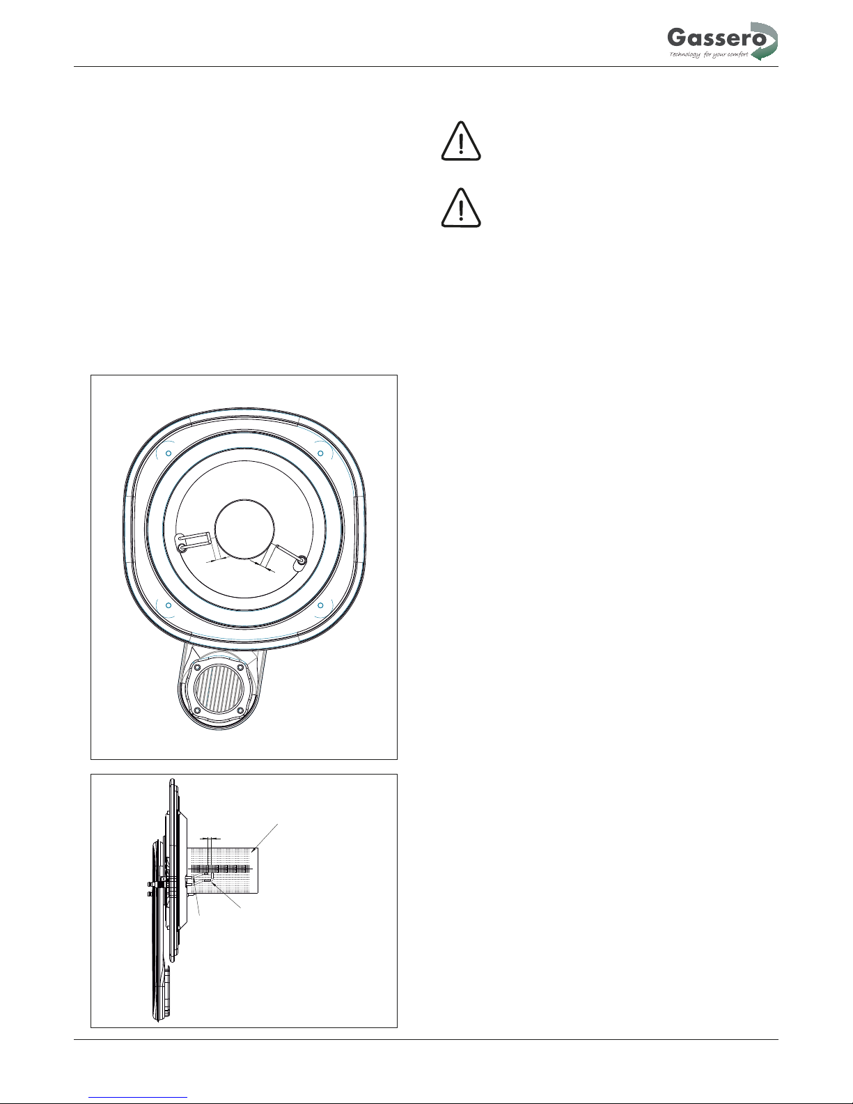
Maintenance
32
Fan
If deposits have been building up on the fan blades, carefully
clean the blades one by one with a soft brush until the material
of the blades is visible again. Work consistently in cleaning the
blades, and do not use too much force or else the fan may get
out of balance and run irregularly.
Ignition / ionisation electrode
Check if the distances between the electrodes and between
electrodes and burner are OK. If not try to bend the electrodes
in the right position. The electrodes are working under high
temperature. Therefore the electrodes become hard and are
difficult to bend. When bending used electrodes there is a risk of
breaking or tearing the electrode. Check if there are any tears/
cracks in the electrodes after bending them. If so then replace
the electrode with a new one. Also change the electrode if any
cracks can be seen in the ceramic electrode insulation. If the
electrode is changed the gasket should also be replaced.
7,00 ( 0,2) mm
-
+
Burner
When defects are found that cannot be fixed by the
service engineer, he has to inform the end user
about the defects, and should advise the end user
to have them fixed.
This should also be mentioned on the service
report of the boiler. During maintenance gas, air,
flue gas and condensate connections are loosened
and remounted. Make sure all the components are
mounted gas-/water tight before recommissioning
the boiler.
8,50 ( 0,2) mm
+
-
5,00 ( 0,5) mm
-
+
Ignition electrode
Earth
Page 34
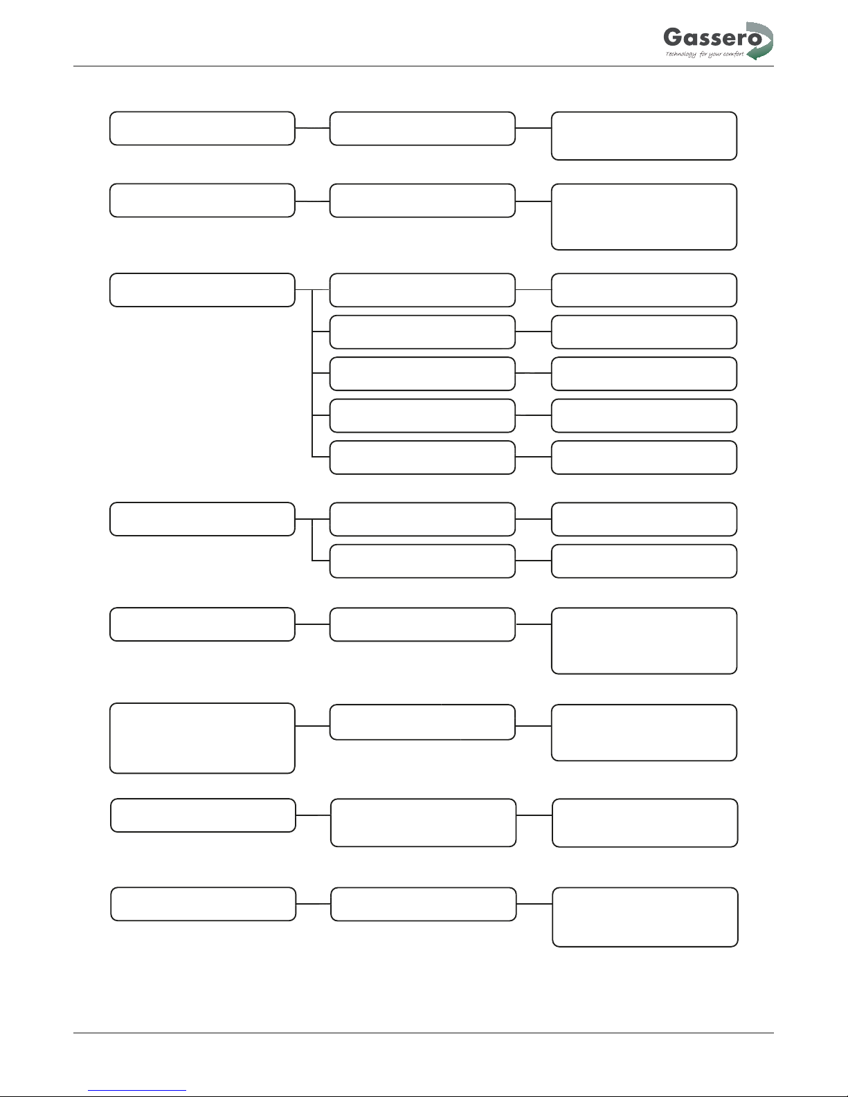
REASON
SOLUTION
PROBLEM
Gas supply circuit
Smell of gas
Check the tightness of the joints
and that the pressure test points
are closed
Burner gas pressure
Irregular combustion
Check adjustment
Diaphragm installed
Check diameter
Condition of the burner
and exchanger
Check they are clean
Exchanger openings blocked
Check the openings are clean
Fan fault
Check operation
Flue gas circuit
Smell of unburned gas
Check:
- The tightness of the joints
- The absence of obstructions
- The quality of combustion
Gas valve
Check that 230 V AC is present
at the terminals on the gas
valve; check wiring and con nections
Burner gas pressure
Delays in ignition with pulsating
operation of the burner
Check adjustment
Ignition electrode
Check positioning and condition
The boiler becomes dirty in a
short time
Check flame colour
Check combustion adjustments
The burner does not start
when recieiving the signal
from the boiler controller
Troubleshooting
No power supply
(the display is blank)
The boiler does not start
Check:
- electrical connections
- fuse
33
Pump fault
The pump does not start
Reset the pump
Replace the pump
Check the electrical connections
of the pump
Combustion
Page 35
Boiler body dirty
The boiler does not reach
the operating temperature
Clean combustion chamber
Insufficient burner flow-rate
Check burner adjustment
Boiler controller
Check correct operation
Check set temperature
No water
Check vent valve
Check pressure in central heating circuit
Air in the system
The heat generator
reaches the temperature
but the central heating
system is cold
Vent the system
Pump fault
Reset the pump
Replace the pump
Check the electrical connections
of the pump
Boiler controller
Thermal overload
on the heat generator
Check correct operation
Check set temperature
Check electrical wiring
Check position of the sensors
REASON
SOLUTION
PROBLEM
Troubleshooting
34
System expansion vessel
Check efficiency
Pressure in heating system circuit
Check charge pressure
Check pressure reducer
System safety valve
Frequent activation of
the system safety valve
Check calibration or efficiency
Page 36
CONTROLS To comply with the Building Regulations, each section must have a tick in one or other of the boxes
TIME & TEMPERATURE CONTROL TO HEATING ROOM T/STAT & PROGRAMMER/TIMER PROGRAMMABLE ROOMSTAT
TIME & TEMPERATURE CONTROL TO HOT WATER CYLINDER T/STAT & PROGRAMMER/TIMER
COMBI BOILER
HEATING ZONE VALVES FITTED NOT REQUIRED
HOT WATER ZONE VALVES FITTED NOT REQUIRED
THERMOSTATIC RADIATOR VALVES FITTED
AUTOMATIC BYPASS TO SYSTEM FITTED NOT REQUIRED
FOR ALL BOILERS CONFIRM THE FOLLOWING
THE SYSTEM HAS BEEN FLUSHED IN ACCORDANCE WITH THE BOILER MANUFACTURER’S INSTRUCTIONS?
THE SYSTEM CLEANER USED
THE INHIBITOR USED
FOR THE CENTRAL HEATING MODE, MEASURE & RECORD
GAS RATE
3
ft /hr
BURNER OPERATING PRESSURE (IF APPLICABLE) mbar
CENTRAL HEATING FLOW TEMPERATURE °C
CENTRAL HEATING RETURN TEMPERATURE °C
FOR COMBINATION BOILERS ONLY
HAS A WATER SCALE REDUCER BEEN FITTED? YES NO
WHAT TYPE OF SCALE REDUCER HAS BEEN FITTED?
FOR THE DOMESTIC HOT WATER MODE, MEASURE & RECORD
GAS RATE
3
ft /hr
MAXIMUM BURNER OPERATING PRESSURE (IF APPLICABLE) mbar
COLD WATER INLET TEMPERATURE °C
HOT WATER OUTLET TEMPERATURE °C
WATER FLOW RATE
lts/min
FOR CONDENSING BOILERS ONLY CONFIRM THE FOLLOWING
THE CONDENSATE DRAIN HAS BEEN INSTALLED IN ACCORDANCE WITH
THE MANUFACTURER’S INSTRUCTIONS? YES
FOR ALL INSTALLATIONS CONFIRM THE FOLLOWING
THE HEATING AND HOT WATER SYSTEM COMPLIES
WITH CURRENT BUILDING REGULATIONS
THE APPLIANCE AND ASSOCIATED EQUIPMENT HAS BEEN INSTALLED AND COMMISSIONED
IN ACCORDANCE WITH THE MANUFACTURER’S INSTRUCTIONS
IF REQUIRED BY THE MANUFACTURER, HAVE YOU RECORDED A CO/CO2RATIO READING? N/A YES CO/CO2 RATIO
THE OPERATION OF THE APPLIANCE AND SYSTEM
CONTROLS HAVE BEEN DEMONSTRATED TO THE CUSTOMER
THE MANUFACTURER’S LITERATURE HAS BEEN LEFT WITH THE CUSTOMER
3
m /hr
3
m /hr
COMMISSIONING ENG’S NAME PRINT DATE
SIGN
BOILER SERIAL No: BOILER MODEL:
GAS BOILER COMMISSIONING CHECKLIST
N/A
N/A
Page 37

Page 38
SERVICE INTERVAL RECORD
It is recommended that your heating system is serviced regularly
and that you complete the appropriate Service Interval Record Below.
Service Provider. Before completing the appropriate Service Interval Record below, please ensure you have carried out the service
as described in the boiler manufacturer’s instructions. Always use the manufacturer’s specified spare part when replacing all controls
SERVICE 1
DATE
ENGINEER NAME
COMPANY NAME
TEL No.
CORGI ID CARD SERIAL No.
COMMENTS
SIGNATURE
SERVICE 2
DATE
ENGINEER NAME
COMPANY NAME
TEL No.
CORGI ID CARD SERIAL No.
COMMENTS
SIGNATURE
SERVICE 3
DATE
ENGINEER NAME
COMPANY NAME
TEL No.
CORGI ID CARD SERIAL No.
COMMENTS
SIGNATURE
SERVICE 4
DATE
ENGINEER NAME
COMPANY NAME
TEL No.
CORGI ID CARD SERIAL No.
COMMENTS
SIGNATURE
SERVICE 5
DATE
ENGINEER NAME
COMPANY NAME
TEL No.
CORGI ID CARD SERIAL No.
COMMENTS
SIGNATURE
SERVICE 6
DATE
ENGINEER NAME
COMPANY NAME
TEL No.
CORGI ID CARD SERIAL No.
COMMENTS
SIGNATURE
SERVICE 7
DATE
ENGINEER NAME
COMPANY NAME
TEL No.
CORGI ID CARD SERIAL No.
COMMENTS
SIGNATURE
SERVICE 8
DATE
ENGINEER NAME
COMPANY NAME
TEL No.
CORGI ID CARD SERIAL No.
COMMENTS
SIGNATURE
SERVICE 9
DATE
ENGINEER NAME
COMPANY NAME
TEL No.
CORGI ID CARD SERIAL No.
COMMENTS
SIGNATURE
SERVICE 10
DATE
ENGINEER NAME
COMPANY NAME
TEL No.
CORGI ID CARD SERIAL No.
COMMENTS
SIGNATURE
Page 39

Page 40

Gassero Isı Teknolojileri Sanayi Limited
Istanbul Endüstri ve Ticaret Serbest Bölgesi (FREE ZONE)
4. Sok. Parsel 110, 34957 Tuzla, Istanbul, Turkey
[email protected] T: +90 216 394 09 85 www.gassero.com
Gassero reserves the right to change specification without prior notice. Consumers statutory rights are not affected.
 Loading...