

-
GASPARDO Seminatrici S.p.A.
SP
IT
USO E MANUTENZIONE
GB
USE AND MAINTENANCE
GEBRAUCH UND WARTUNG
DE
EMPLOI ET ENTRETIEN
FR
EMPLEO Y MANTENIMIENTO
ES
Cod. 19501381 12 / 2002
DORADA

ITALIANO ENGLISH DEUTSCH
INDICE INDEX INHALT
1.0 Premessa
1.1 Descrizione della seminatrice
1.2 Garanzia
1.2.1 Scadenza garanzia
1.3 Dati tecnici
1.4 Identificazione
1.5 Movimentazione
1.6 Disegno complessivo
1.7 Segnali di sicurezza
2.0 Norme di sicurezza e
prevenzione infortuni
3.0 Norme d’uso
3.1 Applicazione al trattore
3.2 Adattamento albero cardanico
3.3 Stabilita’ in trasporto seminatrice-trattore
3.4 Distributore semi
3.5 Sostituzione disco di semina e regolazioni
3.5.1 Sostituzione guarnizione coperchio
3.7 Espulsore seme
3.6 Regolazione del selettore
3.8 Regolazione piastrina antitraboccamento
3.9 Distanza longitudinale di semina
3.10 Dischi di semina
3.11 Tabella distanze longitudinali di semina
3.12 Tabella investimento semi
3.13 Regolazioni
3.13.1 Regolazione profondità assolcatore
3.13.2 Regolazione pressione profondità
assolcatore
3.13.3 Esclusione del seminatore
3.13.4 Scatola trasmissione seminatore
3.14 Segnafile
3.14.1 Segnafile a comando oleodinamico
3.14.2 Segnafile a comando meccanico
3.14.3 Regolazione dischi marcafile
3.15 Distribuzione dei prodotti chimici
3.15.1 Regolazione interratori fertilizzante
3.15.2 Speedy set
3.15.3 Spandiconcime - tabella distribuzione
3.15.4 Speedy set - tabella distribuzione
3.15.5 Microgranulatore - tabella distribuzione
3.16 Aspiratore
3.17 Preparativi alla semina
3.18 Durante la semina
3.19 Allestimenti
4.0 Manutenzione
4.0.1 A macchina nuova
4.0.2 A inizio stagione di semina
4.0.3 Ogni 8 ore lavorative
4.0.4 Ogni 50 ore lavorative
4.0.5 Ogni 6 mesi
4.0.6 Messa a riposo
4.0.7 Lubrificanti consigliati
5.0 Demolizione e smaltimento
6.0 Fornitura
11
11
12
12
12
13
13
14
14
14
15
15
16
17
18
18
18
19
19
20
20
21
21
22
22
23
23
24
25
26
26
27
28
30
30
30
31
31
31
31
31
31
31
5
1.0 Introduction
5
1.1 Description of the seeder
5
1.2 Guarantee
5
1.2.1 Expiry of guarantee
6
1.3 Technical data
6
1.4 Identification
6
1.5 Handling
7
1.6 Assembly drawing
8
1.7 Danger signs
2.0 Safety regulations and
9
accident prevention
3.0 Norme d’uso
3.1 Attachment to the tractor
3.2 Adapting the cardan shaft
3.3 Stability of planting unit and tractor
during transport
3.4 Seed distributor
3.5 Replacing the seeding disk and
adjustments
3.5.1 Replacing the cover seal
3.6 Expeller deeds
3.7 Selector adjustment
3.8 Anti-overflow plate adjustment
3.9 Seeding distance adjustment
3.10 Seed plates
3.11 Longitudinal seeding distance
3.12 Seed chart
3.13 Adjustments
3.13.1 Furrow opener depth adjustment
3.13.2 Furrow opener pressure adjustment
3.13.3 Seeder exclusion
3.13.4 Planting unittransmisssion
3.14 Row marker
3.14.1 Hydraulic row marker
3.14.2 Mechanical row marker automatic control
3.14.3 Row marker disk adjustment
3.15 Distribution of chemical products
3.15.1 Regulating the fertilizer interring hoe
3.15.2 Speedy set
3.15.3 Fertilizer distributor - distribution table
3.15.4 Speedy set - distribution table
3.15.5 Microgranulator - distribution table
3.16 Vacuum pump
3.17 Preparing for seeding
3.18 During seeding
3.19 Preparation
4.0 Maintenance
4.0.1 When the machine is new
4.0.2 At the biginning of the seeding season
4.0.3 Every eight hours of work
4.0.4 Every fifty hours of work
4.0.5 Every six months
4.0.6 Etting aside
4.0.7 Recommended lubricants
5.0 Demolition and disposal
6.0 Supply
1.0 Vorwort
35
1.1 Beschreibung der sämaschine
35
1.2 Garantie
35
1.2.1 Verfall des garantieanspruchs
35
1.3 Technische Daten
36
1.4 Identifizierung
36
1.5 Fortbewegung
36
1.6 Zusammenfassend
37
1.7 Warnsignale
38
2.0 Sicherheits- und
39
41
41
42
42
42
43
43
44
44
44
45
45
46
47
48
48
48
49
49
50
50
51
51
52
52
53
53
54
55
56
56
57
58
60
60
60
61
61
61
61
61
61
61
Unfallverhütungs-Bestimmungen
3.0 Betriebs-anleitungen
3.1 Einbau am schlepper
3.2 Anpassung der gelenkwelle
3.3 Stabilität von Sämaschine-Schlepper
beim Transport
3.4 Säapparat
3.5 Wechseln der aussaatscheiben und
einstellungen
3.5.1 Ersetzen der Deckeldichtung
3.6 Sämenauswerfer
3.7 Einstellung des wählers
3.8 Einstellung der überlaufplatt
3.9 Distanza longitudinale di semina
3.10 Säscheiben
3.11 Tabelle aussaatlängsabstand
3.12 Saatgutbedarftabelle
3.13 Regelungen
3.13.1 Einstellung der Sascharen-Reissertiefe
3.13.2 Einstellung des Schubdrucks des
Säscharen-Reissers
3.13.3 Ausschluss des Saelements
3.13.4 Getriebekasten Sämaschine
3.14 Spurreisser
3.14.1 Hydraulischer spurreisser
3.14.2 Automatiksteuerung des
mechanischen spurreissers
3.14.3 Einstellung der spurmarkiererscheiben
3.15 Verteilung der chemischen produkte
3.15.1 Einstellung der düngereingrabvorrichtungen
3.15.2 Speedy set
3.15.3 Düngerstreuer - Düngermengetabelle
3.15.4 Speedy set - Düngermengetabelle
3.15.5 Mikrogranulatstreuer - Düngermengetabelle
3.16 Gebläse
3.17 Vorbereitungen für die aussaat
3.18 Während der aussaat
3.19 Ausführungen
4.0 Wartung
4.0.1 Bei neuer maschine
4.0.2 Bei beginn der aussaatsaison
4.0.3 Alle 8 betriebsstunden
4.0.4 Alle 50 betriebsstunden
4.0.5 Alle 6 monate
4.0.6 Ruheperioden
4.0.7 Empfohlene schmiermittel
5.0 Zerlegen und entsorgen der
maschine
65
65
65
65
66
66
66
67
68
69
71
71
72
72
72
73
73
74
74
74
75
75
76
77
78
78
78
79
79
80
80
81
81
82
82
83
83
84
85
86
86
87
88
90
90
90
91
91
91
91
91
91
2
-
6.0 Lieferumfang
91
cod. 19501381

FRANÇAIS ESPAÑOL
TABLES DE MATIERES INDICE
1.0 Introduction
1.1 Description de la machine
1.2 Garantie
1.2.1 Expiration de la garantie
1.3 Donnes techniques
1.4 Identification
1.5 Movimentation
1.6 Dessin global
1.7 Signaux de securite
2.0 Normes de securite et de prevention
des accidents
3.0 Normes d’emploi
3.1 Attelage au tracteur
3.2 Adaptation arbre a cardans
3.3 Stabilite pendant le transport semoirtracteur
3.4 Distributeur de graines
3.5 Remplacement et reglages disque
d’ensemencement
3.5.1 Remplacement garniture couvercle
3.6 Ejecteur de graines
3.7 Reglage du selecteur
3.8 Reglage plaque anti-debordement
3.9 Distance longitudinale ensemencement
3.10 Disques de distribution
3.11 Tableau distance longitudinale
d'ensemencement
3.12 Tableau investiment graines
3.13 Reglages
3.13.1 Reglage profondeur soc
3.13.2 Reglages pression de poussée du soc
3.13.3 Exclusion de la machine
3.13.4 Boite de transmission semoir
3.14 Disques à tracer
3.14.1 Disque a tracer hydraulique
3.14.2 Commande automatique disque a
tracer mecanique
3.14.3 Reglage des disques a tracer
3.15 Distribution des produits chimiques
3.15.1 Reglage des bineuses pour l’enfouissement
du fertilisant
3.15.2 Speedy set
3.15.3 Epandeur d’engrais - Tableaux
3.15.4 Speedy set - Tableaux
3.15.5 Microgranulateur - Tableaux
3.16 Depresseur
3.17 Preparatifs pour l’ensemencement
3.18 Pendant l’ensemencement
3.19 Amenagements
4.0 Entretien
4.0.1 Quand la machine est neuve
4.0.2 Debut saison d’ensemencement
4.0.3 Toutes les 8 heures de travail
4.0.4 Toutes les 50 heures de travail
4.0.5 Tous les six mois
4.0.6 Remissage
4.0.7 Lubrifiants conseilles
5.0 Demantelement et elimination
95
95
95
95
96
96
96
97
98
99
101
101
102
102
102
103
103
104
104
104
105
105
106
107
108
108
108
109
109
110
110
111
111
112
112
113
113
114
115
116
116
117
118
120
120
120
121
121
121
121
121
121
1.0 Premisa
1.1 Descripción de la sembradora
1.2 Garantía
1.2.1 Vencimiento de la garantía
1.3 Datos tecnicos
1.4 Identificación
1.5 Manipulación
1.6 Diseño general
1.7 Señales de seguridad y de indicacion
2.0 Normas de seguri-dad y
prevención contra los accidentes
3.0 Normas de manejo
3.1 Aplicación al tractor
3.2 Adaptación del árbol cardán
3.3 Estabilidad durante el transporte
de la sembradora-tractor
3.4 Distribuidor de semillas
3.5 Sustitución del disco de siembra y
regulaciones
3.5.1 Sustitución de la junta de la tapa
3.6 Expulsor para semilla
3.7 Regulación del selector
3.8 Regulación de la plaqueta de
antidesbor-damiento
3.9 Distancia longitudinal de siembra
3.10 Discos de siembra
3.11 Tabla distancia longitudinal de siembra
3.12 Tabla inversión semillas
3.13 Regulaciónes
3.13.1 Regulación de la profundidad del
surcador
3.13.2 Regulación de la presión de empuje
del surcador
3.13.3 Exclusión del sembrador
3.13.4 Caja de transmisión de la sembradora
3.14 Marcadores de hileras
3.14.1 Marcador de hileras hidráulico
3.14.2 Mando automático marcador de
hileras mecánico
3.14.3 Regulación de los discos marcadores de
hileras
3.15 Istribución de los productos químicos
3.15.1 Graduación enterra-dores de fertilizante
3.15.2 Speedy set
3.15.3 Abonador - tabla de distribución
3.15.4 Speedy set - tabla de distribución
3.15.3 Microgranuladore - tabla de distribución
3.16 Aspirador
3.17 Preparaciones para la siembra
3.18 Durante la siembra
3.19 Equipamientos
4.0 Mantenimiento
4.0.1 Cuando la máquina está nueva
4.0.2 Al principio de la estación de siembra
4.0.3 Cada 8 horas laborables
4.0.4 Cada 50 horas laborables
4.0.5 Cada 6 meses
4.0.6 Puesta en reposo
4.0.7 Lubricantes aconsejados
125
125
125
125
126
126
126
127
128
129
131
131
132
132
132
133
133
134
134
134
135
135
136
137
138
138
138
139
139
140
140
141
141
142
142
143
143
144
145
146
146
147
148
150
150
150
151
151
151
151
151
6.0 Fourniture
cod. 19501381
5.0 Desguace y eliminación
121
6.0 Provisión
-
151
151
3

4
-
cod. 19501381

1.0 PREMESSA
IT
ALIANO
Questo manuale descrive le norme d’uso e di manutenzione per
la seminatrice.
Il presente manuale è parte integrante del prodotto, e deve essere custodito in luogo sicuro per essere consultato durante
tutto l'arco di vita della macchina.
Il cliente dovrà provvedere ad istruire il personale sui rischi da
infortunio, sui dispositivi predisposti per la sicurezza e la salute
dell'operatore, sui rischi legati all’esposizione al rumore e sulle
regole antinfortunistiche generali previste da direttive internazionali e dalla legislazione del paese di destinazione delle macchine. In ogni caso la macchina deve essere usata esclusivamente
da operatori qualificati che saranno tenuti a rispettare scrupolosamente le istruzioni tecniche ed antinfortunistiche contenute
nel presente manuale.
E' compito dell'utilizzatore controllare che la macchina venga
azionata unicamente in condizioni ottimali di sicurezza sia per le
persone, per gli animali e per le cose.
Il prodotto è conforme alle seguenti Norme Europee:
- 98/37 CE Direttiva Macchine che abroga e comprende le
Direttive 89/392 CEE, 91/368 CEE, 94/44 CEE e 93/68 CEE.
- 89/336 CEE (Concernente il ravvicinamento delle legislazioni
degli stati membri relative al materiale elettrico destinato ad
essere adoperato entro taluni limiti di tensione).
Per l'adeguamento della macchina sono state utilizzate le seguenti norme:
- EN 292-1:1992 (Sicurezza del macchinario) Concetti fondamentali, principi generali di progettazione. Terminologia,
metodologia di base.
- EN 292-1 A/1:1992
- EN 292-2:1992 (Sicurezza del macchinario) Concetti fondamentali, principi generali di progettazione. Specifiche e principi
tecnici.
- EN 294:1993 (Sicurezza del macchinario) Distanze di sicurezza per impedire il raggiungimento di zone pericolose con gli
arti superiori
- EN 982:1997 (Sicurezza del macchinario) Requisiti di sicurezza relativi a sistemi e loro componenti per trasmissioni
oleoidrauliche e pneumatiche.
- EN 1553:1999 (Macchine agricole) Macchine agricole semoventi, portate, semiportate e trainate - Requisiti comuni di sicurezza.
- pr EN 144045 (Seminatrici - Sicurezza) documento CEN/TC
144 WG 3 n.347 - edizione maggio 2000.
1.1 DESCRIZIONE DELLA SEMINATRICE
Questa attrezzatura agricola, denominata «Seminatrice Pneumatica», può operare solo tramite albero cardanico applicato
alla presa di forza di un trattore agricolo munito di gruppo
sollevatore, con attacco universale ai tre punti.
L'attrezzatura è particolarmente adatta per semine di precisione,
per impieghi polivalenti e con qualsiasi tipo di seme su terreni
lavorati. La seminatrice è a funzionamento pneumatico e può
essere attrezzata con vari accessori ad esempio lo
spandiconcime, il microgranulatore ed elementi di semina aggiuntivi. Il concetto fondamentale di «modularità» è stato sviluppato e abbinato a quello di «semplicità», sia dal punto di vista
costruttivo che da quello di praticità d’uso.
ATTENZIONE
La seminatrice è idonea esclusivamente per semine su terra.
La velocità di lavoro consigliata è di 6÷8 km/h. Il trasporto su
strada della seminatrice deve avvenire con serbatoi vuoti e ad
una velocità massima di 25 km/h. Ogni altro uso diverso da
quello descritto in queste istruzioni può recare danno alla macchina e costituire serio pericolo per l'utilizzatore.
Dal corretto uso e dall’adeguata manutenzione dipende il regolare funzionamento dell’attrezzatura. È consigliabile quindi, osservare scrupolosamente quanto descritto allo scopo di prevenire un qualsiasi inconveniente che potrebbe pregiudicare il buon
funzionamento e la sua durata. Sono fornite, inoltre, tutte le informazioni per il miglior uso della macchina, le istruzioni ed i consigli utili ad una corretta manutenzione.
È altresì importante attenersi a quanto descritto nel presente
manuale in quanto la Ditta Costruttrice declina ogni e qualsiasi
responsabilità dovuta a negligenza ed alla mancata osservanza di tali norme.
La Ditta Costruttrice, è comunque a completa disposizione per
assicurare un’immediata e accurata assistenza tecnica e tutto
ciò che può essere necessario per il miglior funzionamento e la
massima resa dell’attrezzatura.
1.2 GARANZIA
- Verificare all’atto della consegna che l’attrezzatura non abbia
subito danni durante il trasporto e che gli accessori siano integri e al completo.
- Eventuali reclami dovranno essere presentati per iscritto
entro 8 giorni dal ricevimento.
- L’acquirente potrà far valere i suoi diritti sulla garanzia solo
quando egli abbia rispettato le condizioni concernenti la prestazione della garanzia, riportate nel contratto di fornitura.
- La garanzia ha validità di un anno, contro ogni difetto dei mate-
riali, dalla data di consegna dell’attrezzatura.
- La garanzia non include le spese di manodopera e di spedi-
zione (il materiale viaggia a rischio e pericolo del destinatario).
- Sono esclusi dalla garanzia i danni eventualmente causati a
persone o cose.
- La garanzia è limitata alla riparazione o alla sostituzione gra-
tuita del pezzo difettoso, secondo le istruzioni del Costruttore.
I rivenditori o utilizzatori non potranno richiedere nessun indennizzo al Costruttore per eventuali danni che potranno subire (spese di manodopera, trasporto, lavoro difettoso, incidenti diretti o
indiretti, mancati guadagni sul raccolto, ecc.).
1.2.1 SCADENZA GARANZIA
Oltre a quanto riportato nel contratto di fornitura, la garanzia
decade:
- Qualora si dovessero oltrepassare i limiti riportati nella tabella
dei dati tecnici.
- Qualora non fossero state attentamente seguite le istruzioni
descritte in questo manuale.
- In caso di uso errato, di manutenzione difettosa e in caso di
altri errori effettuati dal cliente.
- Qualora siano fatte modifiche senza l’autorizzazione scritta del
costruttore e qualora si siano utilizzati ricambi non originali.
cod. 19501381
-
5

ITALIANO
(A)
USO E MANUTENZIONE
1.3 DATI TECNICI U.M.
Larghezza telaio
Distanza interfila
m
feet
cm
inch
Capacit serbatoio seme l.
Capacit serbatoio concime l.
Presa di forza g.p.m.
Potenza richiesta
Peso (*)
Rilevamento della rumorosit
a vuoto
HP
KW
Kg
lb
Lpam (A)
Lwa
4 file
cm. 75
2,50
8-2"
75
29
320 320 560 320
60
44
550
1210
5 file
cm. 75
3,20
10-5"
60
23
70
51
615
1353
32
540
92,3
109,7
6 file
cm. 75
4,20
14"
75
29
90
66
662
1456
6 file
cm. 45
2,50
8-2"
45
17
70
51
740
1628
(*) Senza spandiconcime e microgranulatore.
I dati tecnici ed i modelli indicati si intendono non impegnativi. Ci riserviamo il diritto di modificarli senza obbligo di preavviso.
1.4 IDENTIFICAZIONE
Ogni singola attrezzatura, è dotata di una targhetta di identificazione (15 Fig. 2), i cui dati riportano:
- Marchio CE;
- Marchio del Costruttore;
- Nome, ragione sociale ed indirizzo del Costruttore;
- Tipo della macchina;
- Matricola della macchina;
- Anno di costruzione;
- Massa, in chilogrammi.
Tali dati vanno sempre citati per ogni necessità di assistenza o
ricambi.
La massa della macchina è evidenziata nella targhetta di identificazione (15 Fig. 2). Tendere la fune ed esguite le operazioni
evitando il dondolamento della macchina, non tenendo la stessa sempre orrizontale. I punti di aggancio sono individuabili dalla presenza del simbolo grafico «gancio» (9 Fig. 3). Per macchine fino a 4 file, agganciare nei punti: A, C e D. Per macchine oltre
le 4 file agganciare nei punti: A, B, C, D e E.
A
1.5 MOVIMENTAZIONE
In caso di movimentazione della macchina, è necessario sollevare la stessa agganciandola agli attacchi predisposti con funi
in stoffa e con paranco o gru idonei e di portata sufficiente (Fig.
1). Questa operazione, per la sua pericolosità, è necessario venga eseguita da personale preparato e ed formato adeguatamente.
BCDE
fig. 1
6
-
cod. 19501381

USO E MANUTENZIONE
ITALIANO
ELEMENTO SEMINATORE
MAIS - GIRASOLE - SOIA
ELEMENTO SEMINATORE
BARBABIETOLE
4
5
6
7
8
20
1
23
11
12
15
fig. 2
1.6 DISEGNO COMPLESSIVO
1 Disco segnafile
2 Serbatoio concime
3 Depressore
4 Vacuometro
5 Distributore aria
6 Serbatoio sementi
7 Regolatore altezza seminatore
8 Ruota di compressione
9 Ruota moto spandiconcime
10 Distributore semi
11 Assolcatore
12 Cardano per moto seminatore
13 Piedino di sostegno
14 Telaio
15 Targhetta di identificazione
16 Regolatore distribuzione fertilizzante (Minimax)
17 Comando segnafile
18 Attacco albero cardanico
19 Sostegno albero cardanico
20 Copriseme
21 Spartizolle
13 14
21
16 1718 19
9
10
cod. 19501381
-
7

ITALIANO
USO E MANUTENZIONE
1.7 SEGNALI DI SICUREZZA
I segnali descritti in Fig. 2, sono riportati sulla macchina (Fig. 3).
Tenerli puliti e sostituirli se staccati o illeggibili. Leggere attentamente quanto descritto e memorizzare il loro significato.
1) Prima di iniziare ad operare, leggere attentamente il libretto
di istruzioni.
2) Prima di eseguire operazioni di manutenzione, arrestare la
macchina e consultare il libretto di istruzioni.
3) Pericolo di schiacciamento in fase di apertura. Tenersi a distanza di sicurezza dalla macchina.
4) Pericolo di essere agganciati dall'albero cardanico. Stare lontani dagli organi in movimento.
5) Pericolo di intrappolamento. Stare lontani dagli organi in
movimento.
6) Pericolo di schiacciamento in fase di chiusura. Tenersi a
debita distanza dalla macchina.
7) Con l'utilizzo di prodotti anticrittogramici, munirsi di adeguate
protezioni.
8) Livello sonoro elevato. Munirsi di adeguate protezioni acustiche.
9) Segnalazione dei punti di aggancio per il sollevamento.
10) Punto di ingrassaggio
1234
56
910
78
fig. 2
8
fig. 3
-
DECALCOMANIE AVVERTIMENTO
Cod. 89900500
WARNING STICKERS
ABZIEHBILDER MIT WARNHINWEISEN
DECALCOMANIE
CALCOMANIAS
cod. 19501381
USO E MANUTENZIONE
ITALIANO
2.0 NORME DI SICUREZZA E PREVENZIONE
INFORTUNI
Fare attenzione al segnale di pericolo riportato nei vari capitoli
di questo manuale.
I segnali di pericolo sono di tre livelli:
PERICOLO: Questo segnale avverte che se le operazioni descrit-
te non sono correttamente eseguite, causano gravi lesioni, morte o rischi a lungo termine per la salute.
ATTENZIONE: Questo segnale avverte che se le operazioni descritte non sono correttamente eseguite, possono causare gravi lesioni, morte o rischi a lungo termine per la salute.
CAUTELA: Questo segnale avverte che se le operazioni descritte
non sono correttamente eseguite, possono causare danni alla
macchina.
Leggere attentamente tutte le istruzioni prima dell’impiego della macchina, in caso di dubbi rivolgersi direttamente ai tecnici
dei Concessionari della Ditta Costruttrice. La Ditta Costruttrice
declina ogni e qualsiasi responsabilità per la mancata osservanza delle norme di sicurezza e di prevenzione infortuni di
seguito descritte.
Norme generali
1) Fare attenzione ai simboli di pericolo riportati in questo manuale e sulla seminatrice.
2) Le etichette con le istruzioni, applicate sulla macchina, danno gli opportuni consigli in forma essenziale per evitare gli
infortuni.
3) Osservare scrupolosamente, con l’aiuto delle istruzioni, le
prescrizioni di sicurezza e di prevenzione infortuni.
4) Evitare assolutamente di toccare in qualsiasi modo le parti
in movimento.
5) Interventi e regolazioni sull’attrezzatura devono essere sempre effettuate a motore spento e con trattore bloccato.
6) Si fa assoluto divieto di trasportare persone o animali sull’attrezzatura.
7) È assolutamente vietato condurre o far condurre il trattore,
con l’attrezzatura applicata, da personale sprovvisto di patente di guida, inesperto e non in buone condizioni di salute.
8) Prima di mettere in funzione il trattore e l’attrezzatura stessa,
controllare la perfetta integrità di tutte le sicurezze per il trasporto e l’uso.
9) Verificare tutt’intorno alla macchina, prima di mettere in funzione l’attrezzatura, che non vi siano persone ed in particolare bambini, o animali domestici e di poter disporre comunque di un’ottima visibilità.
10) Usare un abbigliamento idoneo. Evitare assolutamente abiti svolazzanti o con lembi che in qualche modo potrebbero
impigliarsi in parti rotanti e in organi in movimento.
11) Prima di iniziare il lavoro, familiarizzare con i dispositivi di
comando e le loro funzioni.
12) Iniziare a lavorare con l’attrezzatura solo se tutti i dispositivi
di protezione sono integri, installati e in posizione di sicurezza.
13) È assolutamente vietato stazionare nell’area d’azione della
macchina, dove vi sono organi in movimento.
14) È assolutamente vietato l’uso dell’attrezzatura sprovvista delle protezioni e dei coperchi dei contenitori.
15) Prima di abbandonare il trattore, abbassare l’attrezzatura
agganciata al gruppo sollevatore, arrestare il motore, inserire il freno di stazionamento e togliere la chiave di accensione dal quadro comandi, assicurarsi che nessuno possa
avvicinarsi alle sostanze chimiche.
16) Con trattore in moto, non lasciare mai il posto di guida.
17) Prima di mettere in funzione l’attrezzatura controllare che i
piedini di sostegno siano stati tolti da sotto la seminatrice;
controllare che la seminatrice sia stata correttamente montata e regolata; controllare che la macchina sia perfettamente in ordine, e che tutti gli organi soggetti ad usura e deterioramento siano efficienti.
18) Prima di sganciare l’attrezzatura dall’attacco terzo punto, mettere in posizione di blocco la leva di comando sollevatore e
abbassare i piedini di appoggio.
19) Operare sempre in condizioni di buona visibilità.
20) Tutte le operazioni devono essere eseguite da personale
esperto, munito di guanti protettivi, in ambiente pulito e non
polveroso.
Aggancio al trattore
21) Agganciare l’attrezzatura, come previsto, su di un trattore di
adeguata potenza e configurazione mediante l’apposito dispositivo (sollevatore), conforme alle norme.
22) La categoria dei perni di attacco dell’attrezzatura deve corrispondere a quella dell’attacco del sollevatore.
23) Fare attenzione quando si lavora nella zona dei bracci del
sollevamento, è un’area molto pericolosa.
24) Prestare la massima attenzione nella fase di aggancio e
sgancio dell’attrezzatura.
25) È assolutamente vietato interporsi fra il trattore e l’attacco
per manovrare il comando dall’esterno per il sollevamento
(Fig. 4).
26) È assolutamente vietato interporsi tra il trattore e l’attrezzatura (Fig. 4) con motore acceso e cardano inserito.
È possibile interporsi solo dopo aver azionato il freno di stazionamento ed aver inserito, sotto le ruote, un ceppo o un
sasso di bloccaggio di adeguate dimensioni.
25) L’applicazione di un’attrezzatura supplementare al trattore,
comporta una diversa distribuzione dei pesi sugli assi. È
consigliabile pertanto aggiungere apposite zavorre nella
parte anteriore del trattore in modo da equilibrare i pesi sugli
assi. Verificare la compatibilità delle prestazioni del trattore
con il peso che la seminatrice trasferisce sull’attacco a tre
punti. In caso di dubbio consultare il Costruttore del trattore.
28) Rispettare il peso massimo previsto sull’asse, il peso totale
mobile, la regolamentazione sul trasporto e il codice stradale.
Circolazione su strada
29) Per la circolazione su strada, è necessario attenersi alle
normative del codice stradale in vigore nel relativo Paese.
30) Gli eventuali accessori per il trasporto devono essere muniti
di segnalazioni e protezioni adeguate.
31) È molto importante tenere presente che la tenuta di strada e
la capacità di direzione e frenatura, possono essere influenzati, anche in modo notevole, dalla presenza di un’attrezza-
fig. 4
cod. 19501381
-
9

ITALIANO
USO E MANUTENZIONE
tura portata o trainata.
32) In curva, fare attenzione alla forza centrifuga esercitata in
posizione diversa, del centro di gravità, con e senza l’attrezzatura portata, maggior attenzione anche in strade o terreni
con pendenza.
33) Per la fase di trasporto, regolare e fissare le catene dei bracci laterali di sollevamento del trattore; controllare che siano
ben chiusi i coperchi dei serbatoi delle sementi e del concime; mettere in posizione di blocco la leva di comando del
sollevatore idraulico; agganciare gli elementi seminatori
secondo le indicazioni riportate a pag. 12.
34)
Effettuare gli spostamenti su strada con tutti i serbatoi vuoti.
35) Gli spostamenti fuori dalla zona di lavoro devono avvenire
con l’attrezzatura in posizione di trasporto.
36) La Ditta Costruttrice fornisce a richiesta supporti e tabelle
per segnalazione ingombro.
37) Qualora gli ingombri costituiti da attrezzature portate o semiportate occultino la visibilità dei dispositivi di segnalazione e
di illuminazione della trattrice, questi ultimi devono essere
ripetuti adeguatamente sulle attrezzature, attenendosi alle
normative del codice stradale in vigore nel relativo paese.
Accertarsi, quando in uso, che l’impianto luci sia perfettamente funzionante. Si rammenta inoltre che la corretta sequenza segnaletica dei fanali prevede (Fig. 5):
A - indicatore di direzione
B - luce di posizione rossa
C - luce di stop
44) Controllare spesso e con periodicità la protezione dell’albero cardanico, che deve essere sempre efficiente.
45) Prima di inserire la presa di forza, accertarsi che il numero di
giri sia quello indicato dalla decalcomania apposta sulla
attrezzatura.
46) Prima di inserire la presa di potenza, assicurarsi che non vi
siano persone o animali nella zona d’azione e che il regime
scelto corrisponda a quello consentito. Mai superare il massimo previsto.
47) Fare attenzione al cardano in rotazione.
48) Non inserire la presa di potenza a motore spento o in
sincronismo con le ruote.
49) Disinserire, sempre, la presa di potenza quando l’albero
cardanico supera un angolo di 10 gradi (Fig. 6) e quando
non viene usata.
50) Pulire e ingrassare l’albero cardanico solo quando la presa
di potenza è disinserita, il motore è spento, il freno di
stazionamento è inserito e la chiave staccata.
51) Quando non serve, appoggiare l’albero cardanico sul supporto previsto a tal proposito.
52) Dopo lo smontaggio dell’albero cardanico, rimettere il cappuccio di protezione sull’albero della presa di potenza.
Manutenzione in sicurezza
Durante le operazioni di lavoro e manutenzione, utilizzare gli
idonei dispositivi di protezione individuale (es.):
Albero cardanico
38) L’attrezzatura applicata, può essere comandata solo con albero cardanico completo delle necessarie sicurezze per i
sovraccarichi e delle protezioni fissate con l’apposita
catenella e riposndente ai requisiti della EN1152.
39 Utilizzare esclusivamente l’albero cardanico previsto dal
Costruttore.
40) L’installazione e lo smontaggio dell’albero cardanico devono essere sempre fatti a motore spento.
41) Fare molta attenzione al corretto montaggio e alla sicurezza
dell’albero cardanico.
42) Bloccare la rotazione della protezione dell’albero cardanico
con la catenella in dotazione.
43) Fare molta attenzione alla protezione dell’albero cardanico,
sia in posizione di trasporto che di lavoro.
A
B
C
fig. 5
53) Non procedere con i lavori di manutenzione e di pulizia se
prima non è stata disinserita la presa di potenza, spento il
motore, inserito il freno di stazionamento e bloccato il trattore con un ceppo o un sasso, di dimensioni adeguate, sotto
le ruote.
54) Periodicamente verificare il serraggio e la tenuta delle viti e
dei dadi, eventualmente riserrarli. Per tale operazione è opportuno usare una chiave dinamometrica rispettando il valore di 53 Nm, per viti M10 classe resistenza 8.8, e 150 Nm per
viti M14 classe resistenza 8.8 (Tabella 1).
55) Nei lavori di montaggio, di manutenzione, pulizia, assemblaggio, ecc., con la seminatrice sollevata, mettere per precauzione adeguati sostegni all’attrezzatura.
56) Le parti di ricambio devono corrispondere alle esigenze definite dal costruttore. Usare solo ricambi originali.
Ta b el l a 1
fig. 6
10
-
cod. 19501381

USO E MANUTENZIONE
3.0 NORME D’USO
Per ottenere le migliori prestazioni dell’attrezzatura, seguire attentamente quanto di seguito riportato.
ATTENZIONE
Tutte le operazioni di manutenzione, regolazione e di
approntamento alla lavorazione, devono essere eseguite tassativamente con presa di forza del trattore disinserita,
seminatrice al suolo sui piedini di appoggio, trattore spento,
ben fermo e chiave disinserita.
ITALIANO
3.1 APPLICAZIONE AL TRATTORE
La seminatrice è applicabile a qualsiasi trattore munito di attacco universale a tre punti.
PERICOLO
L’applicazione al trattore è una fase molto pericolosa.
Fare molta attenzione ad effettuare l’intera operazione seguendo le istruzioni, prestando attenzione che nessuna persona si
avvicini alla macchina.
La corretta posizione trattore/seminatrice, viene determinata, ponendo l’attrezzatura ad una distanza, dal trattore, tale che il giunto cardanico resti esteso 5-10 cm dalla posizione di massima
chiusura. A questo punto, procedere come segue:
1) Agganciare la barra della seminatrice (1 Fig. 7) al sollevatore,
bloccarla con le copiglie a scatto.
2) Portarsi con la stessa sotto la verticale dei punti di aggancio
della seminatrice (Fig. 8). Alzare il sollevatore fino allo scatto
del dispositivo di bloccaggio della barra.
3) Agganciare le catene delle barre del sollevatore del trattore.
Mediante gli appositi tiranti bloccare le barre parallelamente al trattore. Quest’ultimo accorgimento deve essere messo in atto per evitare qualsiasi spostamento, in senso orizzontale, della seminatrice.
4) Collegare il terzo punto superiore (2 Fig. 9); la spina va bloc-
cata con l’apposita copiglia; mediante il tirante di regolazione
(3 Fig. 9) fare in modo che la seminatrice sia perpendicolare
al terreno (Fig. 10).
5) Innestare l’albero cardanico e assicurarsi che sia perfetta-
mente bloccato sulla presa di forza. Verificare che la protezione ruoti liberamente e fissarla con l’apposita catenella.
1
fig. 7
fig. 8
2
3
cod. 19501381
fig. 9
fig. 10
-
11

ITALIANO
USO E MANUTENZIONE
3.2 ADATTAMENTO ALBERO CARDANICO
L’albero cardanico, fornito con la macchina, è di lunghezza
standard.
Si può quindi rendere necessario l'adattamento dell'albero
cardanico. In questo caso prima di intervenire sull'albero
cardanico, interpellare il Costruttore del medesimo per l'eventuale adattamento.
CAUTELA
- Quando l’albero cardanico è sfilato al massimo, i due tubi
devono sovrapporsi per almeno 15 centimetri (A Fig. 11).
Quando esso è inserito al massimo, il gioco minimo consentito deve essere di 4 centimetri (B Fig. 11).
- Usando l’attrezzatura su di un altro trattore, verificare quanto
riportato nel punto superiore e verificare che le protezioni
coprano completamente le parti in rotazione dell’albero
cardanico.
ATTENZIONE
Per il trasporto della seminatrice seguire sempre le indicazioni consigliate dal Costruttore.
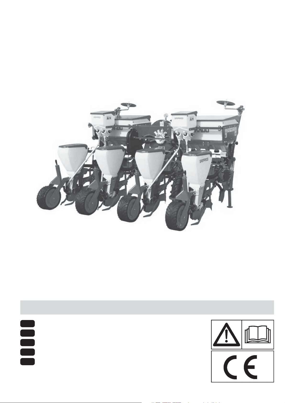
3.3 STABILITA’ IN TRASPORTO SEMINATRICE-TRATTORE
Quando una seminatrice viene accoppiata al trattore, divenendo
ai fini della circolazione stradale parte integrante dello stesso, la
stabilità del complesso trattore-seminatrice può variare causando difficoltà nella guida o nel lavoro (impennamento o
sbandamento del trattore). La condizione di equilibrio può essere ristabilita ponendo nella parte anteriore del trattore un numero sufficiente di zavorre, in modo tale da distribuire i pesi che
gravano sui due assali del tarttore in modo sufficientemente
equo. Per operare in sicurezza è necessario rispettare le indicazioni riportate nel codice della strada il quale prescrive che almeno il 20 % del peso del solo trattore deve gravare sull’asse
anteriore e che la massa gravante sui bracci del sollevatore non
deve essere maggiore del 30 % del peso del trattore stesso.
Queste considerazioni sono sintetizzate nelle formule seguenti:
M x s < 0.2 x T x i + Z x (d+i) Z > (M x s)-(0.2 x T x i)
(d+i)
M < 0.3 x T
La quantità di zavorra che deve essere applicata secondo quanto ricavato dalla formula è da intendersi la minima necessaria
per la circolazione stradale. Se per motivi di prestazione del trattore o per migliorare l’assetto della seminatrice in lavorazione si
ritenesse necessario aumentare tale valore, consultare il libretto del trattore per verificarne i limiti. Qualora la formula per il
calcolo della zavorra desse risultato negativo non è necessaria
l’applicazione di alcun peso aggiuntivo. In ogni caso, sempre
nel rispetto dei limiti della trattrice, al fine di garantire maggior
stabilità durante la marcia è possibile applicare una quantità
congrua di pesi. I simboli hanno il seguente significato:
(per riferimento vedi fig. 12).
A
cm 15 min
Max
B
cm 4 min
fig. 11
ZT
0,2 T
d
fig. 12
fig. 13
i
3.4 DISTRIBUTORE SEMI
All’interno dei distributori (1 Fig. 13) va montato un disco (1 Fig.
14) scelto in funzione della dimensione del seme (il seme non
deve poter entrare nel foro).
I semi, che per risucchio vanno a tappare i fori del disco, verranno poi rilasciati sul terreno.
La seminatrice viene consegnata al cliente con una serie di dischi in dotazione.
La Ditta Costruttrice può fornire all'utilizzatore le seguenti serie
di dischi (pag. 15).
Min
M
s
A
1
12
-
cod. 19501381

USO E MANUTENZIONE
3.5 SOSTITUZIONE DISCO DI SEMINA E REGOLAZIONI
CAUTELA
Tutte le operazioni descritte in questo paragrafo devono essere
eseguite da personale esperto, munito di guanti protettivi, in
ambiente pulito e non polveroso.
- La seminatrice deve essere pulita ed asciutta, staccata dal
trattore e posizionata stabilmente. Se agganciata al trattore,
la presa di potenza deve essere disinserita, il motore spento
, la chiave di avviamento staccata ed il freno di posizionamento
inserito.
- Vanno montati solamente particolari puliti ed in buono stato.
- Il disco deve essere montato con i piolini (1 Fig. 14) rivolti
all’interno del distributore.
- Se al disco mancano piolini o sono piegati significa che sono
entrati corpi estranei nel distributore, in questo caso sostituire il disco.
- Eventuali striature circolari, non devono superare 1/3 dello
spessore del disco.
- Serrare il dado ad alette di chiusura coperchio solamente
con le mani (A Fig. 13).
N.B. Al momento della sostituzione dei dischi usurati, si raccomanda anche la sostituzione della guarnizione del coperchio.
Queste le operazioni da fare:
1) Alzare il singolo seminatore da terra nel seguente modo:
- Agganciare la molla nella posizione 1 (Fig. 15);
- Sollevare il seminatore fino a che non si aggancia;
- Agganciare la molla nella posizione 2 (Fig. 15).
2) Se montata, togliere la vite antirimbalzo (1 Fig. 16);
3) Sganciare l’assolcatore (2 Fig. 16) togliendo la molla (3);
4) Svitare e togliere il dado ad alette (A Fig. 13);
5) Aprire il coperchio del distributore;
6) Inserire o sostituire il disco;
7) Se necessario regolare la piastrina antitraboccamento semi,
come indicato più avanti;
8) Chiudere il coperchio, inserire la rondella elastica e serrare
con il dado ad alette, riagganciare l’assolcatore, rimontare
la vite antirimbalzo (se prevista);
9) Regolare il selettore, come indicato più avanti;
10) Sganciare il seminatore.
fig. 15
ITALIANO
1
fig. 14
1
2
3.5.1 SOSTITUZIONE GUARNIZIONE COPERCHIO
Verificare periodicamente l’uniformità d'usura lungo tutta la
superficie (A Fig. 17) della guarnizione del coperchio distributore seme.
La guarnizione è da sostituire prima che la superficie «A» (Fig.
17), usurandosi per effetto dell'azione del disco, raggiunga la
superficie «B». Va inoltre verificato che non vi siano striature
lungo tutta la superficie «A», causate dal disco.
cod. 19501381
-
fig. 16
A
B
fig. 17
3
2
1
B
A
13

ITALIANO
USO E MANUTENZIONE
3.6 ESPULSORE SEME
Usare l’espulsore solo con semi di barbabietola.
Togliere l’espulsore con semi di grossa pezzatura quali ad es.
mais, girasole, soia, arachidi, etc..
Svitare la vite (1 Fig. 18) e togliere l’espulsore (2).
Montaggio
Posizionare l'espulsore seme (2 Fig. 18) come indicato. Tenendolo premuto contro il bordo ricavato nell'apposita sede (3 Fig.
18), bloccarlo con la vite (1) in dotazione. La vite va montata nel
solo verso indicato in figura. Non interporre alcun tipo di spessore tra l'espulsore e la propria sede. Verificare che l'espulsore
seme sia aderente al disco di semina e che non interferisca con
esso. Sostituire l'espulsore seme quando vi siano evidenti segni di usura e quando il disco risulti danneggiato o deformato.
3.7 REGOLAZIONE DEL SELETTORE
Spostando l’indice (1 Fig. 19 e 20) si comanda un cursore (2 Fig.
19 e 20) che sfiora il disco in prossimità dei fori, provocando la
caduta dei semi in eccesso. Il selettore si regola ad ogni cambio
di seme e di disco, verso i numeri bassi per semi piccoli (Fig.
19) e viceversa per semi grossi (Fig. 20). IMPORTANTE: Il
selettore non regola la portata d’aria nel distributore.
3.8 REGOLAZIONE PIASTRINA ANTITRABOCCAMENTO
La piastrina anti-traboccamento (1 Fig. 21) è regolabile in tre
posizioni e definisce l’ampiezza della luce di ingresso semi (2
Fig. 21), in modo che questi non possano fuoriuscire dal distributore per eccesso di alimentazione. La regolazione è necessaria quando vi sono terreni con notevoli pendenze o i semi sono di
dimensione piccola. In quest’altro caso, potrebbe rendersi necessaria la sostituzione della piastrina standard con una apposita da usarsi esclusivamente per semi piccoli.
Codice per l’ordinazione del pezzo: 22270133.
2
1
fig. 18
3
1
2
fig. 19
1
2
fig. 20
1
2
fig. 21
14
-
cod. 19501381

USO E MANUTENZIONE
3.9 DISTANZA LONGITUDINALE DI SEMINA
La distanza longitudinale di semina è determinata dal numero
di fori presenti sul disco di semina, dal numero di denti e dalla
posizione degli ingranaggi sulla ruota che trasmentte il moto al
cambio e dalla combinazione degli ingranaggi nella scatola del
cambio. Sul coperchio della scatola del cambio è riportata un
tabellina per la regolazione della distanza di semina e una
tabellina che riporta la trasmissione montata sulla ruota che dà
il movimento al cambio.
Per la regolazione della distanza longitudinale di semina operare come di seguito descritto, facendo riferimento alle tabelle riportate a pag. 16:
ITALIANO
2
- Scegliere il disco, da installare sui seminatori, in base alla
dimensione del seme da interrare;
- Verificare sulla seminatrice quanti denti hanno i pignoni (Ruo-
ta) indicati nelle tabelle a pag. 16;
- Cercare la tabella che riporta la coppia di pignoni come quelli
montati sulla seminatrice;
- Dalla colonna del disco scelto, cercare la distanza di semina
desiderata;
- Spostarsi a sinistra e vedere su quale coppia di ingranaggi (A
- B) porre la catena del cambio;
- Per spostare la catena, aprire il coperchio della scatola del
cambio ed allentare la catena (1 Fig. 22) mediante la leva (2);
- Porre la catena sugli ingranaggi individuati ed allinearli (Fig.
23).
- Tendere nuovamente la catena con la leva (2 Fig. 22) e chiude-
re il coperchio.
- Se con i pignoni (ruota) montati sulla seminatrice non si ottie-
ne la distanza di semina desiderata, vedere dalla tabella se
debbono essere invertiti di posizione o sostituiti.
3.10 DISCHI DI SEMINA
(*) Speciale per fagioli.
(**) Si consiglia di sostituire il coperchio del distributore semi
con un apposito coperchio per semi piccoli.
I valori della tabella sono puramente indicativi. La scelta definitiva dei dischi di semina è a totale discrezione dell’utente.
Non si accettano reclami per semine eseguite con dischi non
idonei.
fig. 22
fig. 23
1
cod. 19501381
-
15

ITALIANO
3.11 TABELLA DISTANZE
LONGITUDINALI DI SEMINA
USO E MANUTENZIONE
16
-
cod. 19501381

3.12 TABELLA INVESTIMENTO SEMI
USO E MANUTENZIONE
ITALIANO
cod. 19501381
-
17

ITALIANO
USO E MANUTENZIONE
3.13 REGOLAZIONI
3.13.1 REGOLAZIONE PROFONDITÀ ASSOLCATORE
Per una buona emergenza dei germogli è importante collocare il
seme alla giusta profondità sul letto di semina. Agendo sulla
maniglia si varia la posizione in altezza del falcione assolcatore,
determinando la profondità del solco sul quale deporre il seme
(1 Fig. 24). Un indice numerato consente di registrare ad uguale
misura tutti gli elementi.
Attenzione: l’indice della scala di regolazione è puramente progressivo, non indica in nessun caso una variazione in cm sulla
profondità.
Nella configurazione bietole controllare che il bilancere sia centrato sul solco di semina; eventualmente intervenire regolando
la vite (1) di Figura 25.
3.13.2 REGOLAZIONE PRESSIONE DI SPINTA
DELL’ASSOLCATORE
L’azione del falcione assolcatore di incidere il terreno, è resa
efficace dal carico impresso da detta molla. Diverse situazioni di
lavoro inducono a dover regolare la compressione al suolo; variando la posizione della molla in avanti o all’indietro si imprime
minore o maggiore capacità di penetrazione (1 Fig. 26).
Variare la posizione della molla alla base, sulla piastrina a tre
fori, quando non si raggiungono regolazioni soddisfacenti.
Nella configurazione bietole, l’elemento può essere dotato di
ruotino premiseme. Ruotare la molla (1 Fig. 27) per variare la
pressione del ruotino sul terreno. In caso di terreni umidi escludere l’azione del ruotino: sollevare lo stesso e bloccarlo con la
copiglia (2 Fig. 27).
1
fig. 24
1
fig. 26
fig. 25
1
fig. 27
18
1
-
2
cod. 19501381

USO E MANUTENZIONE
3.13.3 ESCLUSIONE DEL SEMINATORE
Spegnere il trattore e disinserire la chiave di avviamento motore;
Alzare il singolo seminatore da terra nel seguente modo:
- Agganciare la molla nella posizione 1 (Fig. 15);
- Sollevare il seminatore fino a che non si aggancia;
- Agganciare la molla nella posizione 2 (Fig. 15).
Disinserire quindi l’albero di trasmissione del seminatore (Fig.
28) come segue:
- Spingere e mantenere premuto il manicotto (1 Fig. 28) nel
senso indicato dalla freccia, premere in avanti e nello stesso
tempo ruotare la ghiera (2 Fig. 28) fino a liberarla dalla spina in
ferro;
- Tirare indietro, a fine corsa, il manicotto (1 Fig. 28).
- Per ripristinare la trasmissione, spingere in avanti il manicotto
e bloccare nuovamente la ghiera contro la spina in ferro.
ITALIANO
2
1
fig. 28
3.13.4 SCATOLA TRASMISSIONE SEMINATORE
Ogni scatola e provvista di una spina a rottura prestabilita (3 Fig.
29) quando la rotazione del disco di semina forza o si blocca
causa l’ingresso di corpi estranei ai semi (carta, spago ecc.).
Nel caso, scaricare i semi dal contenitore, controllare e pulire il
distributore, controllare i piolini del disco e sostituire la spina a
rottura prestabilita. IMPORTANTE! Non usare spine metalliche.
ATTENZIONE! Non serrare a fondo le viti che reggono la scatola
(4 Fig. 29), l’oscillazione è prevista.
fig. 29
3
4
5
Corretto-
Correct
-Korrector
cod. 19501381
-
19
ITALIANO
USO E MANUTENZIONE
3.14 SEGNAFILE
Il segnafile è un dispositivo che traccia una linea di riferimento
sul terreno, parallela al tragitto del trattore.
Quando il trattore avrà terminato la corsa e invertito la marcia,
procederà correndo con una delle ruote anteriori sulla linea di
riferimento (Fig. 30). Ad ogni nuova passata, la seminatrice dovrà tracciare una linea di riferimento dal lato opposto della passata precedente. L’inversione dei bracci segnafile viene azionato
tramite impianto oleodinamico o a richiesta con comando meccanico automatico.
3.14.1 SEGNAFILE A COMANDO OLEODINAMICO
La seminatrice è dotata di un dispositivo di comando
oleodinamico dei segnafile. I cilindri tuffanti devono essere collegati mediante i rispettivi tubi oleodinamici ai distributori ausiliari della trattrice.
All’interno della borchia del cilindro oleodinamico è contenuto
un grano calibrato che può essere otturato da impurità contenute nell’olio. Se il funzionamento dovesse risultare irregolare
smontare il nipplo e pulire il foro del grano calibrato, quindi rimontare il tutto facendo attenzione al senso di inserimento del
grano nella borchia. A richiesta, il dispositivo segnafile
oleodinamico può essere dotato di una valvola che aziona alternativamente i due bracci.
In questo caso è sufficente un solo distributore oleodinamico
della trattrice. Quando l’impianto non viene utilizzato, proteggere
gli innesti rapidi con gli appositi cappucci (Fig. 31).
fig. 30
D
L
C
DDD
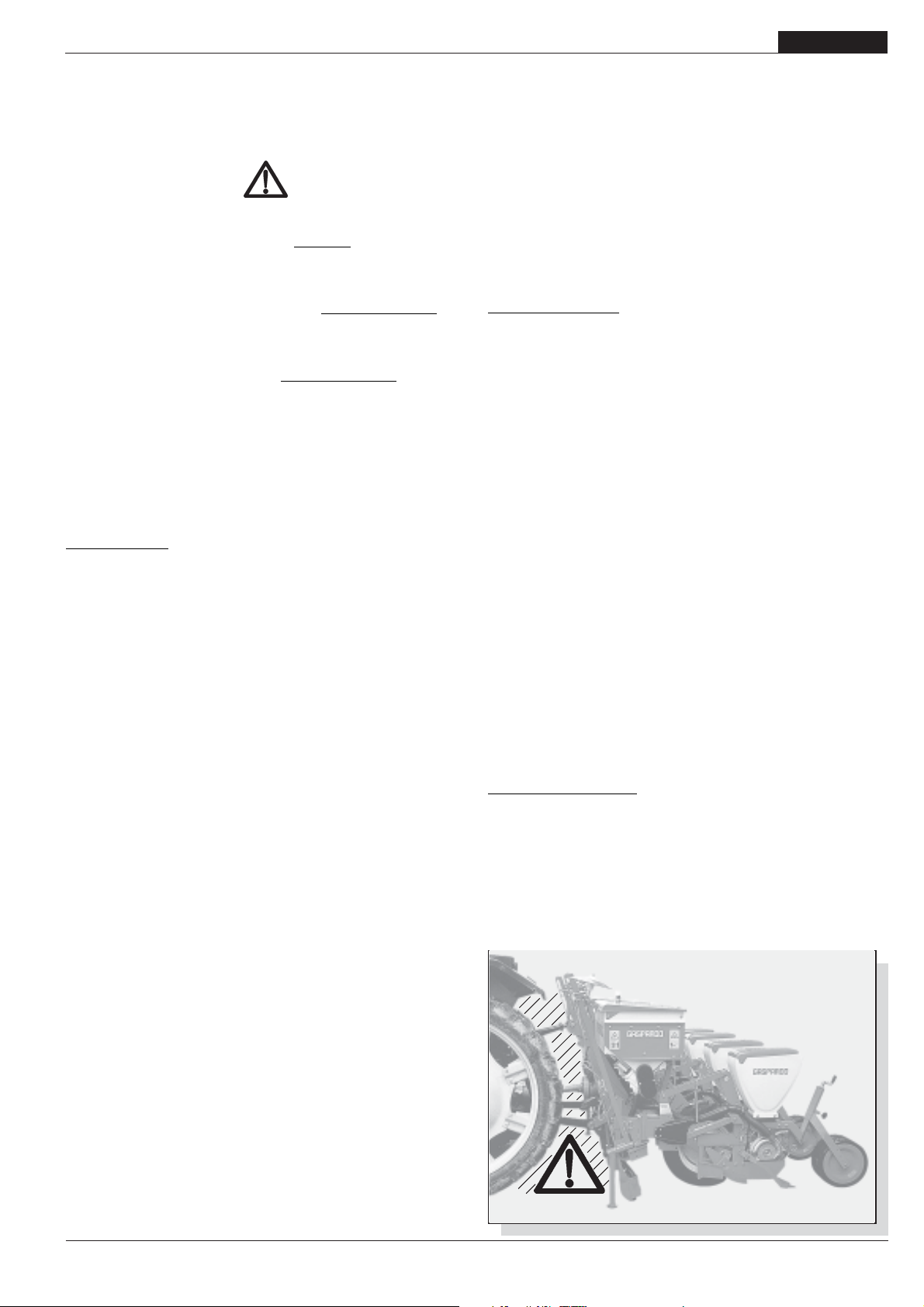
Sicurezza relativa ai circuiti idraulici:
1) Al momento dell’allacciamento dei tubi idraulici all’impianto idraulico del trattore, fare attenzione che gli impianti
idraulici della macchina operatrice e della trattrice non
siano in pressione.
2) In caso di collegamenti funzionali di tipo idraulico tra
trattrice e macchina operatrice, prese e spine dovrebbero
essere contrassegnate per mezzo di colori, in modo da
escludere impieghi errati. Ove si verificasse uno scambio,
sussisterebbe il pericolo di incidente.
3) L'impianto idraulico si trova sotto alta pressione; a causa
del pericolo d'infortunio, in caso di ricerca di punti di perdita vanno ricercati tramite strumenti ed attrezzi idonei.
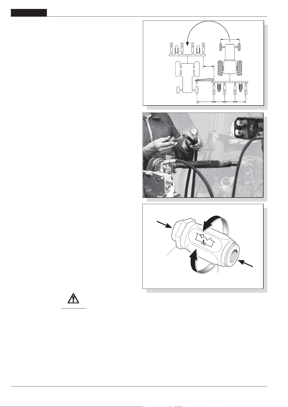
Regolazione degl’impianti:
Gli impianti oleodinamici in dotazione sono integrati con
regolatori di flusso unidirezionali (Fig. 32) che permettono di
regolare la quantità d’olio, in apertura od in chiusura a seconda
del senso di montaggio degli stessi.
Flusso da A a B libero;
Flusso da B a A strozzato (regolato).
Allentare la ghiera di bloccaggio (1) e ruotare la manopola (2)
per la regolazione. Ultimata la regolazione, serrare nuovamente
la ghiera di bloccaggio.
ATTENZIONE
La regolazione deve essere eseguita in modo tale che la velocità di risalita o discesa non danneggi l’integrità della struttura. Mai superare la pressione prevista dell’impianto oleodinamico.
fig. 31
(A)
1
(B)
2
fig. 32
20
-
cod. 19501381

USO E MANUTENZIONE
3.14.2 SEGNAFILE A COMANDO MECCANICO
A richiesta, la Ditta Costruttrice può fornire un set per la trasformazione del segnafile da oleodinamico a meccanico. La richiesta dovrà essere corredata dalla descrizione del tipo e modello
di seminatrice in possesso. Per la trasformazione vengono
riutilizzati tutti i particolari già previsti dalla macchina, la posizione sul telaio del nuovo segnafile non varia.
Il segnafile, viene abilitato a destra o a sinistra del trattore tramite un comando automatico (Fig. 33) azionato dal movimento del
sollevatore del trattore. Per fare ciò è sufficiente alzare ed abbassare una volta il sollevatore del trattore.
Messa a punto
Se il perno (1 Fig. 33) non si aggancia al disco (2) o viceversa
non si sgancia dal medesimo, regolare in altezza i bracci (3). In
posizione di lavoro, le corde devono essere ben tese.
3.14.3 REGOLAZIONE DISCHI MARCAFILE
Fissare sui due bracci del marcafile il manicotto porta disco (1
Fig. 34), senza serrare a fondo i dadi, introdurre il disco e fermarlo con la spina a scatto. Ricavare dalla tabella 2 la distanza (L
Fig. 30) alla quale il disco deve tracciare la linea di riferimento.
Portare il disco alla distanza corretta, inclinarlo leggermente e
serrare a fondo i dadi (Fig. 35). In presenza di terreni normali la
posizione corretta di lavoro del disco è quella indicata dalla Fig.
36 rif A; per terreni forti rovescarlo come da rif. B Fig. 36. Per
distanze non previste dalla tabella, fare riferimento alla seguente regola:
L= D (N +1) - C
2
L= distanza fra l’ultimo elemento esterno e marcafile.
D= distanza fra le file.
N= numero degli elementi in funzione.
C= carreggiata anteriore del trattore.
fig. 34
ITALIANO
1
2
3
fig. 33
1
nr 17
fig. 35
Esempio: D = 75 cm; N = 8 elementi; C = 190 cm
75 (8 + 1) - 190 = 242,5 cm
L =
2
ATTENZIONE
Durante gli spostamenti stradali, ruotare all’interno dell’ingombro macchina i dischi tracciafile (Fig. 37).
Ta b el l a 2
A
Avanzamento
Advancement
Avancement
B
fig. 36
fig. 37
cod. 19501381
-
21
ITALIANO
USO E MANUTENZIONE
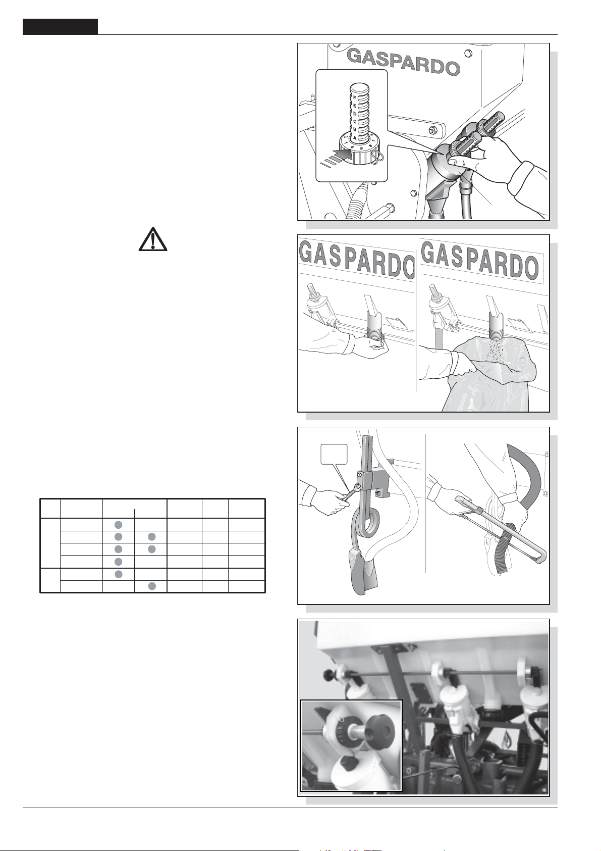
3.15 DISTRIBUZIONE DEI PRODOTTI CHIMICI
La distribuzione dei prodotti fertilizzanti e dei prodotti insetticida,
avviene per mezzo di appositi dosatori (1 Fig. 38) montati sotto ai
rispettivi serbatoi. La regolazione dei dosatori avviene ruotando
la ghiera (2 Fig. 38). In base alla regolazione dei dosatori ed al
peso specifico del prodotto, dalle tabelle di seguito riportate si
può risalire alle quantità di concime e di insetticida necessarie
per coprire un ettaro di terreno.
CARICAMANTO SERBATOI
Il carico dei serbatoi può essere effettuato a mano oppure mediante sollevatore che, con portata superiore a 200 kg, deve essere regolarmente omologato dagli enti preposti. È da ricordare
che il sollevamento di pesi superiori a 30 kg, richiedono o l’intervento di più operatori o l’uso del sopra citato sollevatore meccanico, seguendo le istruzioni riportate nel proprio manuale d’uso
e manutenzione.
ATTENZIONE
- Tutte le operazioni di carico e scarico dei serbatoi
spandiconcime devono essere effettuate con seminatrice
ferma a terra, telaio aperto, azionare il freno di stazionamento,
arrestare il motore e togliere la chiave di accensione dal
quadro comandi. Assicurati che nessuno possa avvicinarsi
alle sostanze chimiche.
- Tutte le operazioni devono essere eseguite da personale
esperto, munito d’adeguate protezioni (tute, guanti, stivali,
maschere, ecc.) in ambiente pulito e non polveroso.
- Non appoggiare in alcun caso sacchi di fertilizzante o altro
sopra i coperchi dei cassoni spandiconcime per evitare la
rottura dei medesimi o arrecare danno a cose o persone.
- Accedere al caricamento dalle fiancate esterne.
- Fare attenzione che durante il riempimento dei serbatoi del
seme, dei fertilizzanti e dell’insetticida, non entrino altri corpi
(spaghi, carta del sacco, ecc.).
- La seminatrice può trasportare sostanze chimiche. Non permettere quindi, che persone, bambini, animali domestici si
avvicinino alla seminatrice.
fig. 38
fig. 39
2
19
NR -.........
1
1
1
1
CAPACITÀ SERBATOI
Serbatoio
(mm)
500
A
A - Spandiconcime; B - Microcranulatore; (*) - Solo con serbatoi in metallo.
850
1100
1500
250
B
250
Materiale
Metallo Plastica
Capacit
Rialzo
(Litri)
92,5
(Litri)
157
203 97(*) 980(*)
277
15
16
Top
(Litri)
I distributori in materiale plastico, non necessitano di
lubrificazione. Si raccomanda, a fine lavoro, un’accurata pulizia
del serbatoio, in modo particolare per quelli del fertilizzante. Svitare i tappi delle bocchette di scarico, raccogliere eventuale prodotto residuo (Fig. 39) e lavare abbondantemente con acqua.
Attenersi alle norme ecologiche per lo smaltimento dei liquidi
inquinanti.
3.15.1 REGOLAZIONE INTERRATORI FERTILIZZANTE
I falcioni per l’interramento del fertilizzante agiscono parallelamente alla fila di semina, ad una distanza standard.
Prima di utilizzare la seminatrice, verificare che tale distanza
risulti essere la medesima per tutti i falcioni nonchè sia adeguata per i quantitativi ettaro e la tipologia di fertilizzante che
vorrete distribuire, in modo da non arrecare danno alla coltura. In caso contrario, modificare la distanza.
Registrare inoltre la profondità di interramento del fertilizzante,
variando l’altezza della molla (Fig. 40).
fig. 40
fig. 41
22
-
cod. 19501381
USO E MANUTENZIONE
ITALIANO
Eseguita questa operazione, si consiglia di tagliare la parte eccedente di tubo flessibile, in modo da evitare la formazione di
pieghe che potrebbero ostruire la discesa del fertilizzante (Fig.
40).
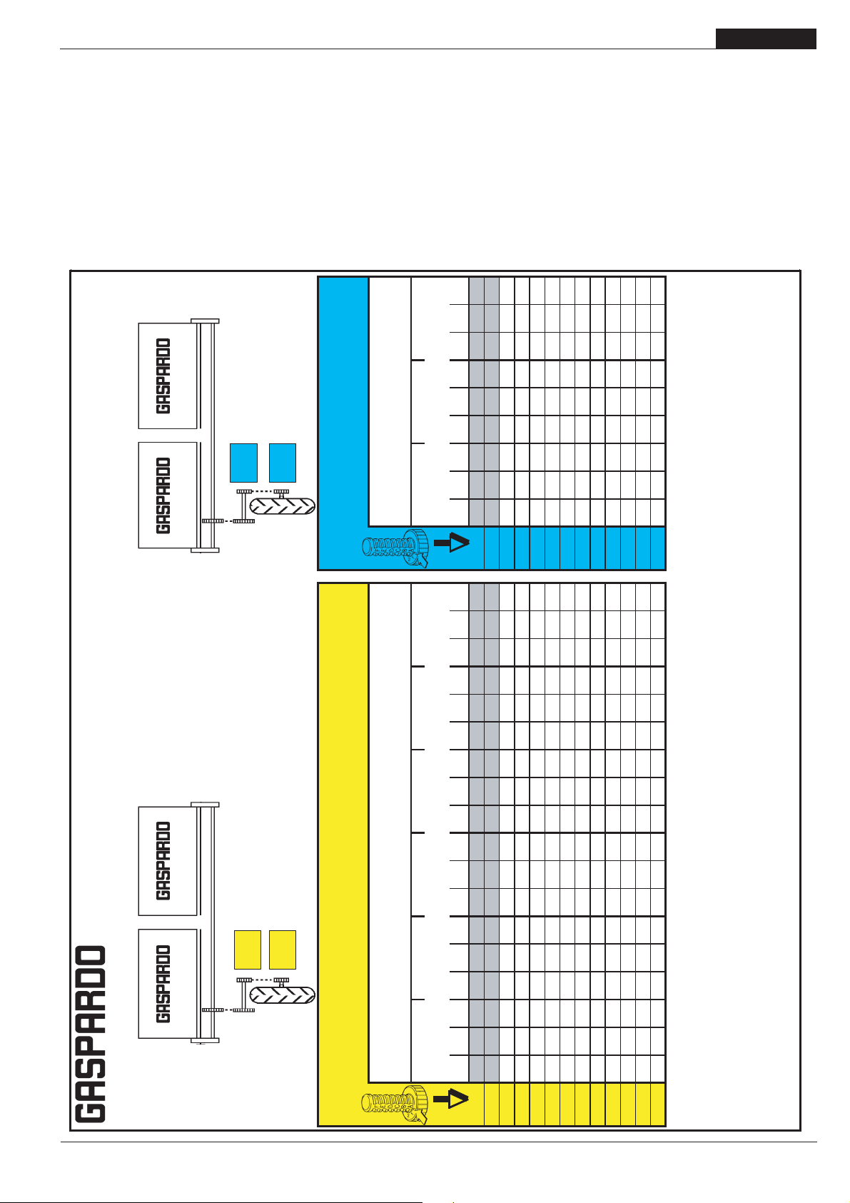
3.15.2 SPEEDY SET
Il serbatoio spandiconcime può essere equipaggiato con lo
SPEEDY SET (Fig. 41), che permette di regolare i dosatori
volumetrici MINIMAX (propriamente modificati) su ogni singolo
serbatoio con una sola manovra. Controllare periodicamente
che le portine di scorrimento siano allineate. A seguire viene
riportata la tabella di distribuzione (19702951) adatta a tale
regolazione.
Posici n
- Reihenabstand
- Distancia entre las hileras
bersetzung d entrainemet
Trasmissione ruota motrice
Transmission drive wheel
Z25
Transmision roue motrice
Z15
- Prospectos de distribuci n
Position of distributor adjustment
Transmici n de la rueda motriz
Position reglage distributeur -
Row spacing
Interfila -
Distance entre les lignes
Abonadora
Z20
- D ngermengetabelle
Z20
Einstellung Einstellvorrchtung -
Posizione regolazione distributore -
5.00/80
R15 (*)
regulaci n distribuidor
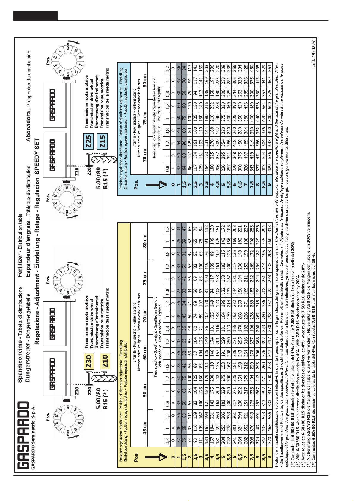
3.15.3 SPANDICONCIME Tabella della quantità in Kg/Ha
ATTENZIONE: il dosatore MINIMAX, regolato nelle prime posizio-
ni (B0÷C0 o 1÷1,5 con SPEEDY SET) a causa della ridotta apertura può intasarsi, soprattutto se si impiegano concimi a
granulometria irregolare. Se la quantità di concime che si vuole
erogare ricade nelle prime posizioni (righe oscurate nella tabella) contattare la casa Costruttrice. I valori della tabella costituiscono solo valori indicativi, in quanto il peso specifico e la grandezza dei granelli sono spesso diversi. In ogni caso fare sempre
riferimento al peso specifico riportato sulla confezione del prodotto o, in mancanza, rivolgersi direttamente al produttore. Per
valori del peso specifico diversi da quelli forniti nelle tabelle,
contattare la Gaspardo Seminatrici S.p.A.
437 546 655 408 510 612 382 478 574
G-10
Les valeurs indiquØes
. - Los valores de la tabla son
The chart values are only approximate, since the specific
.
20%
.
- Spezifisches Gewicht
- Peso especifico : Kg/dm‡
Specific weight
Poids specifique
Peso specifico -
64 80 96 60 75 89 56 70 84
B-0
94 118 141 88 110 132 82 103 124
B-5
124 155 187 116 145 174 109 136 163
C-0
158 197 237 147 184 221 138 173 207
C-5
188 235 282 176 220 264 165 206 247
D-0
218 273 328 204 255 306 191 239 287
D-5
249 311 373 232 290 348 218 272 326
E-0
282 353 424 264 329 395 247 309 371
E-5
313 391 469 292 365 438 274 342 410
F-0
343 429 514 320 400 480 300 375 450
F-5
376 471 565 351 439 527 329 412 494
G-0
407 508 610 380 475 569 356 445 534
G-5
.
.
20%
Cod. 19700821
D ngerstreuer
- Tableaux de distribution
- Tabella di distribuzione
- Distribution table
Fertilizer
Espandeur d’engrais
Spandiconcime
GASPARDO Seminatrici S.p.A.
Z20
Trasmissione ruota motrice
Transmission drive wheel
Z30
Z20
bersetzung d entrainemet
Transmision roue motrice
Transmici n de la rueda motriz
Z10
5.00/80
R15 (*)
Position reglage distributeur
- Reihenabstand
- Distancia entre las hileras
Einstellung Einstellvorrchtung -
Row spacing
Interfila -
Distance entre les lignes
Position of distributor adjustment -
- Spezifisches Gewicht
- Peso especifico : Kg/dm‡
Specific weight
Poids specifique
Peso specifico -
45 cm 50 cm 60 cm 70 cm 75 cm 80 cm 70 cm 75 cm 80 cm
Posizione regolazione distributore -
Posici n regulaci n distribuidor
0,8 1 1,2 0,8 1 1,2 0,8 1 1,2 0,8 1 1,2 0,8 1 1,2 0,8 1 1,2 0,8 1 1,2 0,8 1 1,2 0,8 1 1,2
55 69 83 50 62 75 41 52 62 35 44 53 33 41 50 31 39 47
B-0
81 102 122 73 92 110 61 76 92 52 65 78 49 61 73 46 57 69
B-5
107 134 161 97 121 145 81 101 121 69 86 104 64 81 97 60 76 91
C-0
137 171 205 123 154 184 102 128 154 88 110 132 82 102 123 77 96 115
C-5
163 203 244 146 183 220 122 153 183 105 131 157 98 122 146 92 114 137
D-0
189 236 283 170 212 255 142 177 212 121 152 182 113 142 170 106 133 159
D-5
215 269 322 193 242 290 161 202 242 138 173 207 129 161 193 121 151 181
E-0
244 305 366 220 275 329 183 229 275 157 196 235 146 183 220 137 172 206
E-5
270 338 405 243 304 365 203 253 304 174 217 261 162 203 243 152 190 228
F-0
296 370 444 267 333 400 222 278 333 190 238 286 178 222 267 167 208 250
F-5
325 407 488 293 366 439 244 305 366 209 261 314 195 244 293 183 229 275
G-0
351 439 527 316 395 475 264 330 395 226 282 339 211 264 316 198 247 297
G-5
378 472 566 340 425 510 283 354 425 243 303 364 227 283 340 212 266 319
G-10
I valori della tabella costituiscono solo valori indicativi, in quanto il peso specifico e la grandezza dei granelli sono spesso diversi. -
. - Die Tabellenwerte sind Richtwerte, da das spezifische Gewicht und die Gr e der K rner oft unterschiedlich sind. -
weight and the size of the granules often differ
sur le tableau de rØglage costituent simplement des valeurs donnØes titre indicatif car le poids spØcifiqueet la grandeur des grains sont souvement diffØrents
diminuire i valori della tabella del
7.50 R16
. Con ruote
4%
las dimensiones de los granos son, generalmente, diferentes.
diminuire i valori della tabella del
6.50/80 R15
) Con ruote da
*
*
(
slo indicativos, ya que el peso espec fico y
die Mengen der Tabelle um 20% vermindern.
With 6.50/80 R15 wheels decrease distribution quantity by 4% . With 7.50 R16 wheels decrease by 20%
Avec roues de 6.50/80 R15 diminuer les donnØes du tableau de 4% . Avec roues de 7.50 R16 diminuer de 20%
)
)
*
(*) Mit Bereifung 6.50/80 R15 die Mengen der Tabelle um 4% vermindern. Mit Bereifung 7.50 R16
(
(
disminuir los mismo del
7.50 R16
. Con ruedas
4%
disminuir los valores de la tabla del
6.50/80 R15
) Con ruedas
*
(
cod. 19501381
-
23
ITALIANO
3.15.4 SPEEDY SET
USO E MANUTENZIONE
24
-
cod. 19501381
USO E MANUTENZIONE
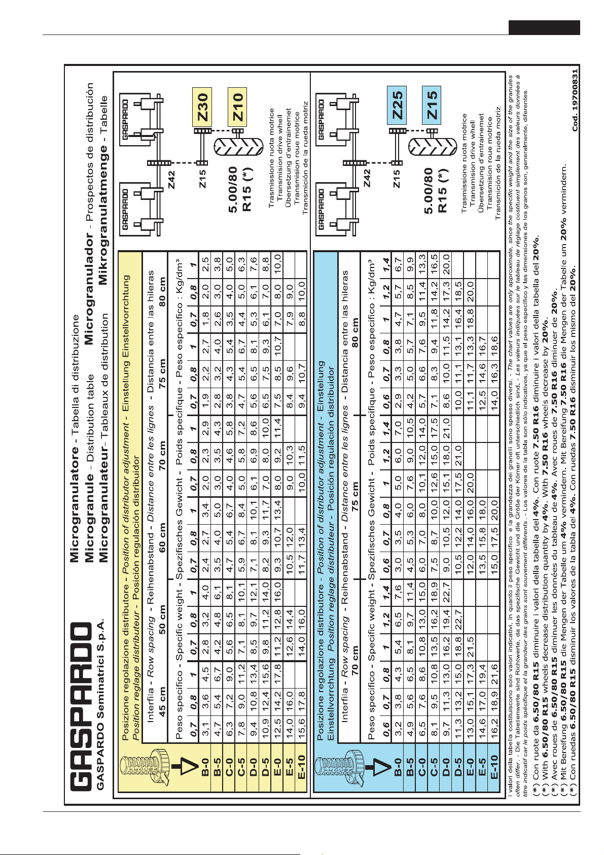
3.15.5 MICROGRANULATORE Tabella della quantità in Kg/Ha
ITALIANO
cod. 19501381
-
25

ITALIANO
USO E MANUTENZIONE
3.16 DEPRESSORE
L’aspiratore (Fig. 42) crea il vuoto all’interno dei distributori, permettendo che i semi vengano risucchiati sui fori del disco.
Determinante per il rendimento dell’aspiratore, e perciò per la
buona riuscita della semina, è la tensione e lo stato di deterioramento della cinghia.
Una cinghia correttamente tesa non deve cedere alla pressione della mano.
ATTENZIONE
Assicurarsi che il cardano sia scollegato dalla presa di potenza prima di procedere alle operazioni di seguito riportate:
Controllo della cinghia:
- Togliere il carter di protezione;
- Allentare le viti (1 Fig. 42);
- Allentare il dado (2 Fig. 42);
- Se consumata, sostituire la cinghia;
- Mettere in trazione la cinghia serrando la vite (3 Fig. 42);
- Serrare le viti prima allentate e rimontare il carter di protezione.
Vacuometro
Il vacuometro (Fig. 43) è lo strumento di misura del vuoto; quello
fornito dal costruttore indica valori di aspirazione da 0 a -100
mbar. I valori indicativi medi dell’aspirazione per semi grossi
sono di -55 ÷ -60 mbar, per semi piccoli -40 ÷ -45 mbar.
Rispettare il numero di giri della presa di forza indicato.
NR -
17
3
2
1
1
NR -
-70
-80
19
-60
-90
-100
-50
Mbar
fig. 42
-40
-30
-20
-10
0
3.17 PREPARATIVI ALLA SEMINA
È importante regolare correttamente la seminatrice in campo.
PERICOLO
Attenersi esclusivamente alla descrizione e alla sequenza delle
operazioni di seguito riportate:
- Dal posto di guida del trattore sollevare la seminatrice;
- Azionare la presa di potenza a 540 giri al minuto e porre la
turbina ad una rotazione di 500 giri/min;
- Con la leva del cambio, mettere in folle il motore del trattore;
- Frenare il trattore e se occorre, bloccarlo ponendo dei ceppi di
adeguate dimensioni alle ruote;
- Accertarsi che nessuno possa avvicinarsi al posto di guida del
trattore;
- Controllare che tutti gli alberi di trasmissione dei distributori
seme siano perfettamente agganciati.
- Controllare accuratamente le parti mobili, gli organi di trasmis-
sione e di distribuzione semi.
- Caricare i serbatoi seme: è da ricordare che il sollevamento di
pesi superiori a 30 kg, richiedono o l’intervento di più operatori
o l’uso del sopra citato sollevatore meccanico, seguendo le
istruzioni riportate nel proprio manuale d’uso e manutenzione.
fig. 43
fig. 44
ATTENZIONE
Tutte le operazioni devono essere eseguite da personale esperto, munito d’adeguate protezioni (tute, guanti, stivali, maschere,
ecc.) in ambiente pulito e non polveroso. Fare attenzione che
durante il riempimento dei serbatoi del seme, dei fertilizzanti e
dell’insetticida, non entrino altri corpi (spaghi, carta del sacco,
ecc.).
- Girare con le mani, nel senso di marcia, la ruota che trasmette
il moto al cambio della seminatrice;
- Regolare il selettore controllando dalla grata trasparente (Fig.
44) che il disco porti un solo seme per foro;
- Dalla «Tabella investimento semi» a pagina 17 è possibile
conoscere in anticipo quanti semi saranno necessari.
26
-
fig. 45
cod. 19501381

USO E MANUTENZIONE
CAUTELA
Rimuovere i piedini di appoggio (Fig. 45).
- Procedere con la semina: dopo alcuni metri controllare se i
distributori depongono un seme per volta.
A fine semina scaricare i semi residui dalla porta (Fig. 46) del
distributore tramite l’apposito scivolo di scarico in dotazione.
3.18 DURANTE LA SEMINA
- Ogni albero di trasmissione è provvisto di un limitatore di
coppia con avvisatore acustico (5 Fig. 29) che, alla rottura
della spina (3 Fig. 29), segnala l'anomalia od il guasto
avvenuto nel distributore. Se succede, fermarsi prontamente e rimediare l'accaduto, rimuovere la spina rotta e sostituirla (usare il cacciaspine in dotazione).
- Alla fine di ogni corsa, durante la manovra di inversione di
marcia, tenere sempre azionata la presa di forza ad un regime di giri sufficiente a mantenere i semi attaccati ai dischi
dei distributori.
- Durante la semina controllare di sovente la distribuzione
dei semi, se imprecisa, regolare il selettore.
- Se manca o diminuisce l’aspirazione, controllare che i tubi
non siano forati o intasati ed in tal caso sostituirli o pulirli,
controllare eventualmente anche la cinghia dell’aspiratore.
CAUTELA
- La forma, le dimensioni e il materiale delle spine elastiche
degli alberi di trasmissione, sono state scelte per prevenzione. L’uso di spine non originali o più resistenti, può comportare gravi danneggiamenti alla seminatrice.
- Avviare progressivamente la presa di forza, gli strappi
bruschi sono dannosi per la cinghia dell’aspiratore.
- Evitare di effettuare curve con la macchina interrata, e
non lavorare in retromarcia. Sollevarla sempre per i cambiamenti di direzione e per le inversioni di marcia.
- Non lavorare con la presa di potenza in sincronismo con
le ruote.
- Non superare i 540 giri al minuto della presa di potenza.
- Non spingere mai il trattore a regime massimo di giri.
- Mantenere una velocità di semina compatibile al tipo e
lavorazione del terreno al fine di avitare rotturre o
danneggiamenti.
- Abbassare la seminatrice con il trattore in movimento onde
evitare l’intasamento o danneggiamenti ai falcioni
assolcatori, per lo stesso motivo è sconsigliata la manovra di retromarcia con la seminatrice a terra.
- Fare attenzione che durante il riempimento dei serbatoi
del seme, dei fertilizzanti e dell’insetticida, non entrino altri corpi (spaghi, carta del sacco, ecc.).
ITALIANO
fig. 46
PERICOLO
La seminatrice può trasportare sostanze chimiche. Non permettere quindi, che persone, bambini, animali domestici si avvicinino
alla seminatrice.
ATTENZIONE
Non appoggiare in alcun caso sacchi di fertilizzante o altro sopra
i coperchi dei cassoni spandiconcime per evitare la rottura dei
medesimi o recare danno a cose o persone. Accedere al
caricamento dalle fiancate.
Nessuno deve potersi avvicinare ai contenitori delle sostanze
chimiche, nonché di aprirli quando la seminatrice è in funzione o
in procinto di funzionare.
Utilizzare i dispositivi di protezione individuali prescritti dai produttori delle sostanze chimiche note.
cod. 19501381
-
27

ITALIANO
USO E MANUTENZIONE
3.19 ALLESTIMENTI
In tutti i modelli gli elementi seminatori sono collegati indipendentemente al telaio mediante meccanismi a parallelogramma
articolato, pur presentando alcune specifiche particolarità a seconda del tipo di seme da distribuire e delle caratteristiche del
terreno sul quale si opera.
fig. 47
a) elementi seminatori per semine di profondità
sono disponibili due diversi tipi di elementi per l'impianto medio
profondo in relazione alla rugosità del letto di semina:
- per terreni finemente preparati è consigliabile adottare
assolcatori a falcione con spartizolle e ruote di compressione
(fig. 47);
- per terreni caratterizzati da una maggiore rugosità ed in presenza di residui appare invece più opportuno utilizzare utensili
a doppio disco disposti a monte degli assolcatori a falcione
seguiti da ruote di compressione (fig. 48);
Per quanto riguarda gli elementi chiudisolco a seconda delle
caratteristiche dei terreni sono disponibili 3 diverse soluzioni
(fig. 49):
ruota farmflex (Ø=370mm) consigliata su terreni umidi e sab-
1)
biosi;
2) ruote a "V" in gomma più adatte su terreni umidi e "difficili".
3) ruote a "V" in ferro indicate per terreni di medio impasto ed
asciutti;
b) elementi seminatori per semine superficiali
L'elemento seminatore per semine superficiali è a bilanciere
standard con ruote in gomma: quella anteriore "schiacciazolle"
a profilo bombato (avente Ø=280 mm), seguita dal ruotino
premiseme, anch'esso in gomma, con copriseme indipendenti
(fig. 50).
Per quanto riguarda gli elementi coprisolco a seconda delle caratteristiche dei terreni sono disponibili 3 diverse soluzioni (fig.
51):
1) ruota in gomma a profilo concavo (Ø=290 mm) specifica per
barbabietole;
2) ruote a "V" in gomma indicate per terreni umidi e difficili;
3) ruota farmflex (Ø=370 mm) indicata per terreni umidi e sab-
biosi.
28
fig. 48
fig. 49
1
2
3
-
1
2
cod. 19501381
fig. 50
fig. 51
3

USO E MANUTENZIONE
ITALIANO
REGOLAZIONE RUOTE POSTERIORI DI COMPRESSIONE
Notevole importanza, nella semina di qualità, hanno gli
allestimenti posteriori degli elementi seminatori.
Teli elementi sono determinanti nella profondità di semina e
nella copertura della semente dopo la deposizione.
RUOTA FARMFLEX 370 mm
Semine medio profonde
(mais, girasole, soia)
max 10 cm
RUOTA FARMFLEX 370 mm
Semine superficiali
(barbabietole)
Vanno quindi opportunamente regolati in base al tipo di semina
ed al tipo di terreno, variando la posizione delle ruote posteriori
sul proprio supporto come indicato da schema a seguire.
max 7 cm
max 3,5 cm
max 3,5 cm
max 5 cm
RUOTA IN GOMMA
A PROFILO CONCAVO 290 mm
Semine superficiali
(barbabietole)
max 5 cm
RUOTE A V IN GOMMA
1 - 2
max 4,5 cm
max 14 cm
cod. 19501381
-
max 6,5 cm
max 11 cm
29

ITALIANO
USO E MANUTENZIONE
4.0 MANUTENZIONE
Sono di seguito elencate le varie operazioni di manutenzione da
eseguirsi con periodicità. Il minor costo di esercizio ed una lunga durata della seminatrice dipende, tra l’altro, dalla metodica e
costante osservanza di tali norme. Il sistema d’aggancio a scatto, pratico e sicuro, permette di sollevare il seminatore per fare
manutenzioni e controlli (Fig. 15).
CAUTELA
- I tempi di intervento elencati in questo manuale hanno solo
carattere informativo e sono relativi a condizioni normali di
impiego, possono pertanto subire variazioni in relazione al
genere di servizio, ambiente più o meno polveroso, fattori
stagionali, ecc. Nel caso di condizioni più gravose di servizio,
gli interventi di manutenzione vanno logicamente incrementati.
- Prima di iniettare il grasso negli ingrassatori, è necessario
pulire con cura gli ingrassatori stessi per impedire che il
fango, la polvere o corpi estranei si mescolino con il grasso,
facendo diminuire, o addirittura annullare, l’effetto della
lubrificazione.
ATTENZIONE
- Tenere sempre gli olii ed i grassi al di fuori della portata dei
bambini.
- Leggere sempre attentamente le avvertenze e le precauzioni indicate sui contenitori e sulle schede di sicurezza dei
prodotti.
- Evitare il contatto con la pelle.
- Dopo l’utilizzo lavarsi accuratamente e a fondo.
- Trattare gli olii usati e i liquidi inquinanti in conformità con le
leggi vigenti.
4.0.1 A MACCHINA NUOVA
- Dopo le prime otto ore di lavoro, controllare il serraggio di tutte
le viti.
4.0.2 A INIZIO STAGIONE DI SEMINA
- Azionare la seminatrice a vuoto, il flusso dell’aria libera le
condutture dalla presenza di condensa e rimuove eventuali
impurità.
fig. 52
3
1
6
4
2
5
30
-
cod. 19501381

USO E MANUTENZIONE
ITALIANO
4.0.3 OGNI 8 ORE LAVORATIVE
- Ingrassare le crociere dell’albero cardanico.
- Ingrassare il perno dei dischi segnafile (1 Fig. 52).
- Se sono montate le ruote a «V» in ferro, ingrassarne i mozzi (3
Fig. 52)
- Controllare la tensione della cinghie dell’aspiratore (Fig. 42).
4.0.4 OGNI 50 ORE LAVORATIVE
- Verificare lo stato dei dischi forati, se mancano piolini o sono
piegati sostituire il disco con un ricambio originale; eventuali
striature circolari sui dischi non devono superare di 1/3 lo spessore dei dischi stessi.
- Pulire con acqua all’interno del distributore dei semi, eventualmente sostituire la guarnizione del coperchio.
- Ingrassare il perno del braccio segnafile (6 Fig. 52).
4.0.5 OGNI 6 MESI
- Oliare la vite dei regolatori di altezza (2 Fig. 52).
- Ingrassare i cuscinetti oscillanti delle ruote motrici (4 Fig. 52).
- Ingrassare la coppia conica degli alberi cardanici (5 Fig. 52).
4.0.6 MESSA A RIPOSO
A fine stagione, o nel caso si preveda un lungo periodo di riposo,
è consigliabile:
- Lavare l’attrezzatura abbondantemente con acqua, in particolar
modo i serbatoi delle sostanze chimiche, quindi asciugarla.
- Controllarla accuratamente ed eventualmente sostituire le parti
danneggiate o usurate.
- Regolare la cinghia del depressore ed eventualmente sostituirla.
- Serrare a fondo tutte le viti e i bulloni.
- Ingrassare le catene di trasmissione, oliare tutte le catene di
trasmissione, passare con del lubrificate tutte le parti non verniciate.
- Proteggere l’attrezzatura con un telo.
- Infine, sistemarla in un ambiente asciutto, stabilmente, e fuori
dalla portata dei non addetti.
Se queste operazioni vengono fatte con cura, il vantaggio sarà
solo dell’utilizzatore in quanto alla ripresa del lavoro, troverà un’attrezzatura in perfette condizioni.
4.0.7 LUBRIFICANTI CONSIGLIATI
- Per la lubrificazione in generale si consiglia: OLIO AGIP BLASIA
460 SAE 85W/140 o equivalente, per le specifiche vedere l'ulti-
ma pagina di copertina.
- Per tutti i punti di ingrassaggio, si consiglia: GRASSO AGIP GR
MU EP 2 o equivalente, per le specifiche vedere l'ultima pagina
di copertina.
5.0 DEMOLIZIONE E SMALTIMENTO
Operazione da eseguirsi a cura del Cliente.
Prima di effettuare la demolizione della macchina, si raccomanda di verificare attentamente lo stato fisico della stessa, valutando che non ci siano parti della struttura eventualmente soggette
a possibili cedimenti strutturali o rotture in fase di demolizione.
Il Cliente dovrà agire in osservanza delle leggi vigenti nel proprio
paese in materia di rispetto e tutela dell'ambiente.
ATTENZIONE
Le operazioni di demolizione della macchina devono essere
eseguite solamente da personale qualificato, dotato di adeguati dispositivi di protezione individuale (calzature di sicurezza e guanti) e di utensili e mezzi ausiliari.
ATTENZIONE
Tutte le operazioni di smontaggio per la demolizione devono
avvenire a macchina ferma e staccata dal trattore.
Si raccomanda, prima di demolire la macchina, di rendere innocue tutte le parti suscettibili di fonti di pericolo e quindi:
· rottamare la struttura tramite ditte specializzate,
· asportare l'eventuale apparato elettrico attenendosi alle leggi
vigenti,
· recuperare separatamente oli e grassi, da smaltire tramite le
ditte autorizzate, nel rispetto della normativa del Paese di utilizzo della macchina.
All'atto della demolizione della macchina la marcatura CE dovrà
essere distrutta assieme al presente manuale.
6.0 FORNITURA
Dotazione di serie:
- Libretto USO E MANUTENZIONE;
- Libretto PARTI DI RICAMBIO;
- Albero cardanico;
- Puleggia per trattori con presa di forza a 540 g/1'.
- Una serie di dischi di semina;
- Segnafile;
- N. 4 ingranaggi (2 montati) per trasmissione ruota-cambio;
- Cacciaspine;
- N. 10 spine di sicurezza per limitatore di coppia cardani dei
seminatori;
- N. 4 ingranaggi (2 montati) per la trasmissione spandiconcime
e/o microgranulatore (se forniti con la macchina);
- Set di segnalazione visiva (luci posteriori).
cod. 19501381
Dotazione a richiesta. La seminatrice può essere dotata di:
- Versione assolcatore a doppio disco;
- Versione a bilanciere;
- Con contaettari elettronico;
- Con monitor controllo seme;
- Con spartizolle fisso;
- Con segnafile automatico o oleodinamico;
- Con ruote di compressione in gomma da mm 370;
- Con ruote di compressione a «V» in ferro o in gomma;
- Con ruota di compressione da mm 290 concava in gomma
completa di ruotino premiseme;
- Con ruote motrici 6.50/80x15;
- Con doppia trasmissione a ruota libera;
- Con doppia coppia rompitraccia;
- Con puleggia per trattori con presa di forza a 1000 g/1'.
Si ricorda infine che la Ditta Costruttrice è sempre a disposizione per qualsiasi necessità di assistenza e ricambi.
-
31

Notes
32
-
cod. 19501381

Notes
cod. 19501381
-
33

34
-
cod. 19501381

1.0 INTRODUCTION
ENGLISH
This booklet describes the regulations for use, maintenance for
seeding machine.
This booklet is an integrating part of the product, and must be
kept in a safe place for consultation during the whole life span of
the machine.
The customer should instruct personnel on accident risks, on
the operator safety devices provided, on noise emission risks
and on general accident prevention regulations provided for by
the international directives and by the law in the country in which
the machines are used.
In any case, the machine should be used exclusively by skilled
operators who will be held to follow scrupulously the technical
and accident-prevention instructions in this manual.
It is the user's responsibility to check that the machine is operated
only in optimum conditions of safety for people, animals and
property.
The product complies with the following European Standards:
- 98/37 CE Machine Directive that abrogates and includes
Directives 89/392 EEC, 91/368 EEC, 94/44 EEC and 93/68 EEC.
- 89/336 EEC (Concerning the bringing together of member
countries' regulations on electrical material destined for use
within certain voltage limits).
For machine conformity the following standards have been used:
- EN 292-1:1992 (Safety of machinery) Basic concepts, general
design principles. Terminology and basic methodology.
- EN 292-1 A/1:1992
- EN 292-2:1992 (Safety of machinery) Basic concepts, general
design principles. Technical specifications and principles.
- EN 294:1993 (Safety of machinery) Safety distances to prevent
danger zones being reached by the upper limbs.
- EN 982:1997 (Safety of machinery) Safety requirements
regarding systems, and their components, for hydraulic and
pneumatic drives.
- EN 1553:1999 (Agricultural machines) Self-propelled
agricultural machines, mounted, semi-mounted and towed Common safety requirements.
- pr EN 144045 (Planting units - Safety) document CEN/TC 144
WG 3 n° 347 - May 2000 edition.
1.1 DESCRIPTION OF THE SEEDER
This agricultural equipment, called “SP Pneumatic Seeder”, can
only operate by means of a Cardan shaft applied to the power
take-off of an agricultural tractor equipped with a lifting unit, with
a three-point universal joint.
The equipment is ‘particularly suitable for precision seeding, for
multi-purpose use and on any kind of tilled land . The seeding
machine is pneumatically operated and may be equipped with
various accessories, such as, for example, a manure spreader,
granulate distribution, and additional seeding elements.
The fundamental concept of the “modularity” has been developed
and combined with that of “simplicity”, not only for structure but
also for practicality of use.
CAUTION
The seeder is suitable exclusively for seeding in the ground.
The recommended working speed is 6-8 km/h. The planting
unit must only be transported by road with the tanks and
hoppers empty and at max speed of 25 km/h. Any other use
different from that described in these instructions could cause damage to the machine and represent a serious hazard for
the user.
Regular operation depends on the correct use and adequate
maintenance of the equipment. It is advisable therefore to
observe scrupulously what is described in order to prevent any
inconveniences that could prejudicate proper operation and
duration. All the information required for using the machine in the
best way and instructions and advice for its correct maintenance
are also supplied. It is just as important to keep to what is
described in this booklet since the Manufacturer declines all
responsibility due to negligence and non-observance of these
rules.
At any rate the Manufacturer is available to assure immediate
and accurate technical assistance and all that may be necessary
for the improved operation and better performance of the
equipment.
1.2 GUARANTEE
- On delivery, check that the equipment has not been damaged
during transport and that the accessories are integral and complete.
- Possible claims must be presented in writing within eight (8)
days of receipt.
- The purchaser will enforce his rights on the guarantee only
when he has respected the conditions concerning the benefit
of the guarantee, set out in the supply contract.
- The guarantee is valid for a year, against all defects of material,
from the date of delivery of the equipment.
- The guarantee does not include working and shipping costs
(the material is shipped at the consignee’s own risk).
- Obviously, all damage to persons or things are excluded from
the guarantee.-
- The guarantee is limited to the repair or replacement of the
defective piece, according to the instructions of the
Manufacturer.
Dealers or users may not claim any indemnity from the
Manufacturer for any damage they may suffer (costs for labor,
transport, defective workmanship, direct or indirect accidents,
loss of earnings on the harvest, etc.).
1.2.1 EXPIRY OF GUARANTEE
Besides what has already been set out in the supply contract,
the guarantee expires:
- If the limits set out in the technical data table are overshot.
- If the instructions set out in this booklet have not been carefully
followed.
- If the equipment is used badly, defective maintenance or other
errors by the client
- If modifications have been carried out without written
authorization of the manufacturer and if non original spare parts
have been used.
cod. 19501381
-
35
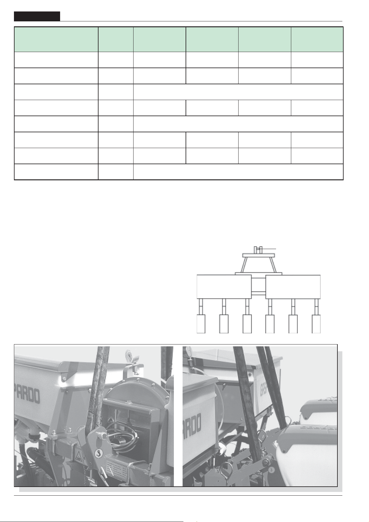
ENGLISH
(A)
USE AND MAINTENANCE
1.3 TECHNICAL DATA U.M.
Toolbar width
Row distance
m
feet
cm
inch
Seed hopper capacity l.
Fertilizer hopper capacity l.
PTO rpm
Power required
Weight (*)
No-load noise detection
HP
KW
Kg
lb
Lpam (A)
Lwa
4 row
cm. 75
2,50
8-2"
75
29
320 320 560 320
60
44
550
1210
5 row
cm. 75
3,20
10-5"
60
23
70
51
615
1353
109,7
32
540
92,3
6 row
cm. 75
4,20
14"
75
29
90
66
662
1456
6 row
cm. 45
2,50
8-2"
45
17
70
51
740
1628
(*) Without fertilizer and microgranulator.
The technical data and the models provided must be considered as non binding. We reserve the right to change them without notice.
1.4 IDENTIFICATION
Each single piece of equipment, is equipped with an identification
plate (15 Fig. 2), which bears:
- CE mark.
- Manufacturers mark.
- Name, business name and address of the Manufacturer.
- Type of machine.
- Registration of the machine.
- Year of manufacture.
- Mass, in Kilograms.
This information must always be quoted whenever assistance
or spare parts are needed.
The mass of the machine is on the identification Plate (15 Fig. 2).
Stretch the rope to keep the machine level.
The hook points can be detected by finding the “hook” symbol
(fig. 3). For machines of up to four rows, hook up at points: A, C
and D. For machines of more than 4 rows hook up at points: A, B,
C, D and E.
A
1.5 HANDLING
If the machine has to be handled, it should be lifted by hooking
cloth ropes to the attachment points provided and using a
suitable hoist or crane with sufficient capacity (Fig. 1). Because
of the danger involved, this operation should be carried out by
trained and responsible personnel.
BCDE
fig. 1
36
-
cod. 19501381
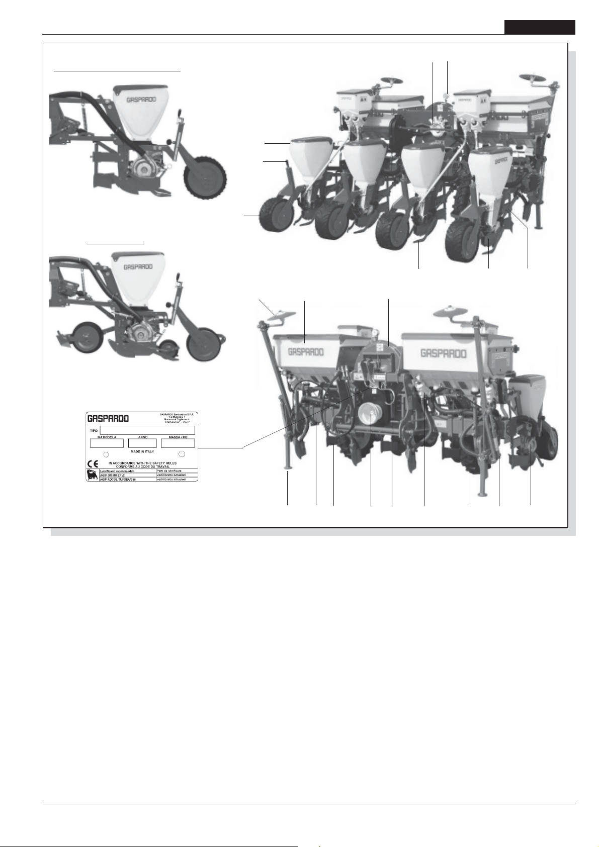
USE AND MAINTENANCE
ENGLISH
PLANTING UNIT
CORN - SUNFLOWER - SOYA
PLANTING UNIT
SUGARBEET
4
5
6
7
8
20
1
23
11
12
15
fig. 2
1.6 ASSEMBLY DRAWING
1 Row marker disk
2 Manure/fertilizer tank
3 Fan
4 Vacuum meter
5 Air distributor
6 Seed tank
7 Seeder height adjuster
8 Compression wheel
9 Manure spreader driving wheel
10 Seed distributor
11 Lister
12 Planter driving universal joint
13 Supporting foot
14 Frame
15 Identification plate
16 Manure/fertilizer distribution Adjuster (Minimax)
17 Row marker control
18 Cardan shaft linkage
19 Cardan shaft support
20 Seed covering.
21 Sod breaker
13 14
21
16 1718 19
9
10
cod. 19501381
-
37

ENGLISH
USE AND MAINTENANCE
1.7 DANGER SIGNS
The signs described in fig. 2 are reproduced on the machine
(Fig. 3). keep them clean and replace them if they should come
off or become illegible. Carefully read each description and learn
their meanings by heart.
1) Before operating, carefully read the instruction booklet.
2) Before carrying out maintenance, stop the machine and
consult the instruction booklet.
3) Danger of getting squashed during opening. Keep at a safe
distance from the machine.
4) Danger of getting hooked by the Cardan shaft. Keep away
from moving parts.
5) Danger of getting trapped. Keep away from moving parts.
6) Danger of getting squashed during closure. Keep at a safe
distance from the machine.
7) When using anticryptogamic chemicals, use adequate
protection.
8) High noise level. Use adequate acoustic protection.
9) Signs the hooking points for lifting.
10) Greasing point.
1234
56
910
78
fig. 2
38
fig. 3
-
DECALCOMANIE AVVERTIMENTO
Cod. 89900500
WARNING STICKERS
ABZIEHBILDER MIT WARNHINWEISEN
DECALCOMANIE
CALCOMANIAS
cod. 19501381
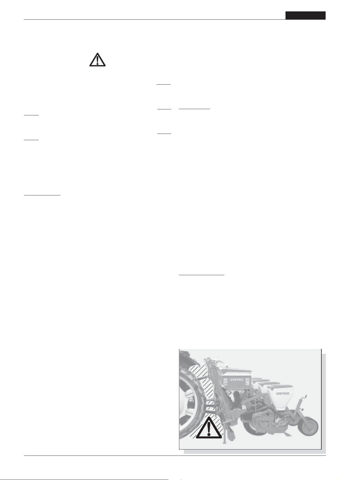
USE AND MAINTENANCE
ENGLISH
2.0 SAFETY REGULATIONS AND ACCIDENT
PREVENTION
Pay attention to danger signs, where shown, in this booklet.
There are three levels of danger signs:
DANGER. This sign warns that the operations described cause
serious lesions, death or long term health risks, if they are not
carried out correctly.
ATTENTION. This sign warns that the operations described could
cause serious lesions, death or long term health risks, if they
are not carried out correctly.
CAUTION. This sign warns that the operations described could
cause serious damage to the machine. if they are not carried out
correctly.
Carefully read all the instructions before using the machine; if
in doubt, contact the technicians of the Manufacturer’s dealer.
The manufacturer declines all responsibility for the nonobservance of the safety and accident prevention regulations
described below.
General norms
1) Pay close attention to the danger signs in this manual and
on the seeder.
2) The labels with the instructions attached to the machine give
abbreviated advice for avoiding accidents.
3) Scrupulously observe, with the help of the instructions, the
safety and accident prevention regulations.
4) Avoid touching the moving parts in any way whatsoever.
5) Any work on and adjustment to the machine must always be
done with the engine switched off and the tractor blocked.
6) People or animals must not, under any circumstances be
transported on the equipment.
7) It is strictly prohibited to drive the tractor, or allow it to be
driven, with the equipment attached by persons not in
possession of a driver’s license, inexpert or in poor conditions
of health.
8) Before starting the tractor and the equipment, check that all
safety devices for transport and use are in perfect working
order.
9) Before starting up the equipment, check the area surrounding
the machine to ensure that there are no people, especially
children or pets, nearby, and ensure that you have excellent
visibility.
10) Use suitable clothing. Avoid loose clothing or garments with
parts that could in any way get caught in the rotating or moving
parts of the machine.
11) Before starting work, familiarize yourself with the control
devices and their functions.
12) Only start working with the equipment if all the protective
devices are in perfect condition, installed and in the safe
position.
13) It is absolutely prohibited to stand within the machine’s radius
of action where there are moving parts.
14) It is absolutely forbidden to use the equipment without the
guards and container covers.
15) Before leaving the tractor,lower the equipment hooked to the
lifting unit, stop the engine, pull the hand brake and remove
the key from the dashboard, make sure that the chemical
substances safely out of reach.
16) The driver’s seat must never be left when the tractor engine
is running.
17) Before starting the equipment, check that the supporting feet
have been removed from under the seeder; check that the
seeder has been correctly assembled and regulated; check
that the machine is in perfect working order, and that all the
parts subject to wear and tear are in good condition.
18) Before releasing the equipment from the third point
attachment, put the hoist command lever into the locked
position and lower the support feet.
19) Only operate when visibility is good.
20) All operations must be carried out by expert personnel,
equipped with protective gloves, in a clean and dust-free
environment.
Tractor hitch
21) Hook the equipment to a suitable, sufficiently-powered tractor
by means of the appropriate device (lifter), in conformity with
applicable standards.
22) The class of the equipment attachment pins must be the
same as that of the lifter attachment.
23) Take care when working within the range of the lifting arms
as this is a very dangerous area.
24) Be very careful when hooking and unhooking the equipment.
25) It is absolutely forbidden to stand between the tractor and
linkage for manoeuvring the lifting controls from the outside
(Fig. 4).
26) It is absolutely forbidden to stand in the space between the
tractor and the equipment (Fig. 4) with the engine running.
It is possible to work between the tractor and the equipment
only after the parking brake has been applied and a suitably
sized blocking wedge or stone has been placed under the
wheels.
27) The attaching of additional equipment onto the tractor brings
about a different distribution of weight on the axles. Check
the compatibility of the tractor performance with the weight
that the seeder transfers onto the three-point linkage. If in
doubt consult the tractor Manufacturer.
28) Comply with the maximum admissible weight for the axle,
the total mobile weight, transport regulations and the highway
code.
Transport on Road
29) When driving on public roads, be sure to follow the highway
code of the country involved.
30) Any transport accessories must be provided with suitable
signs and guards.
31) It is very important to remember that road holding capacity as
well as direction and braking capacity can be influenced,
sometimes con-siderably, by equipment being either carried
or towed.
fig. 4
cod. 19501381
-
39

ENGLISH
USE AND MAINTENANCE
32)When negotiating curves, be aware of the variation in
centrifugal force exerted in a position other than that of the
center of gravity, with and without the equipment in tow. Also
pay greater attention on sloping roads or ground.
33) For transport, adjust and fasten the lateral lifting arm chains
of the tractor; check that the seed and fertilizer hopper covers
are closed properly; lock the hydraulic lifting control lever;
hook the seeders unit following the instructions referring on
page 40.
34) Road movements must be performed with all tanks empty.
35) For displacements beyond the work area, the equipment must
be placed in the transportation position.
36) Upon request the Manufacturer will supply supports and
tables for signaling of dimensions.
37) When the dimensions of carried or partially-carried equipment
conceal the tractor’s signalling and lighting devices, these
must also be installed on the equipment itself, in conformity
with regulations of the highway code of the country involved.
When in operation make sure that the lighting system is in
perfect working order. It is also important to remember that
the correct signalling sequence of the headlights includes
(Fig. 5):
A - Direction indicator;
B - Red position light;
C - Stop light
Cardan shaft
38) The equipment installed can only be controlled by means of
the Cardan shaft complete with the necessary overload safety
devices and guards fastened with the appropriate chain.
39) Only the Cardan shaft supplied by the Manufacturer must be
used.
40) The engine must not be running when installing and removing
the Cardan shaft.
41) Care must be taken regarding the safety and correct assembly
of the Cardan shaft.
42) Use the chain provided to stop the Cardan shaft from rotating.
43) Always check carefully that the Cardan shaft guard is always
in position, both during trans-portation and operation.
47) Frequently and set intervals check the Cardan shaft guard, it
must always be in excellent condition.
45) Before engaging the power take-off, check that the set rpm
corresponds to that indicated by the sticker on the equipment.
46) Before inserting the power take-off, make sure that there are
no people or animals nearby and that the rpm selected
corresponds to that permitted. Never exceed the maximum
admissible speed.
47) Watch out for the rotating universal joint.
48) Do not insert the power take-off with the engine off or
synchronized with the wheels.
49) Always disconnect the power take-off when the Cardan shaft
is at too wide an angle (never more than 10° - Fig. 6) and
when it is not being used.
50) Only clean and grease the Cardan shaft when the power
take-off is disconnected, the engine is off, the hand brake
pulled and the key removed.
51) When not in use, place the Cardan shaft on the support
provided for it.
52) After having dismantled the Cardan shaft, place the protective
cover on the power take-off shaft again.
Maintenance in safety
During work and maintenance operations, use suitable personal protection gear:
53) Do not proceed with maintenance and cleaning if the power
take-off has not been disconnected first, the engine power
off, the hand brake pulled and the tractor blocked with a
wooden block or stone of the right size under the wheels.
54) Periodically check that the bolts and nuts are tight, and if
necessary tighten them again. For this it would be advisable
to use a torque wrench, respecting the values of 53 Nm for
M10 bolts, resistance class 8.8, and 150 Nm for M14 bolts
resistance class 8.8 (Table 1).
55) During assembling, main-tenance, cleaning, fitting, etc., with
the seeding machine raised, place adequate supports under
the equipment as a precaution.
56) The spare parts must correspond to the manufacturer’s
specifications. Use only original spares.
fig. 5
fig. 6
40
A
B
C
-
Ta bl e 1
cod. 19501381

USE AND MAINTENANCE
3.0 NORME D’USO
To obtain the best performance from the equipment, carefully
follow what is set out below.
ATTENTION
All maintenance , adjustment and preparation for operation,
must only be carried out with the power take-off of the
tractor disconnected, the seeder on the ground on the
supporting feet, the tractor not running, the wheels blocked
and the key turned off.
ENGLISH
3.1 ATTACHMENT TO THE TRACTOR
The seeder may be attached to any tractor fitted out with a threepoint universal joint.
DANGER
The attachment to the tractor is a very dangerous phase. Be
very careful to carry out the entire operation by following the
instructions and make sure that no one comes near the
machine.
The correct tractor/seeder position, is determined by placing the
equipment at a distance from the tractor such that the Cardan
joint remains extended 5-10 cm from the position of maximum
closure. At this point, proceed as follows:
1) Hook the bar of the planting unit (1 Fig. 7) to the hoist, and
lock it with the snap-in pins.
2) Take it under the upright of the hitching points of the planting
unit (Fig. 8). Raise the lifter until the locking device of the bar
snaps into place.
3) Hook the chains to the lifting bars of the tractor. Using the
appropriate tie-rods block the bars parallel to the tractor. This
expedient must be used to avoid any kind of horizontal
movement the seeder.
4) Connect the third upper point (2 fig.9) ; the pin will be blocked
with the appropriate split pin; use the adjustment tie-rod (3
fig. 9) to keep the seeders parallel to the ground (fig. 10).
5) Connect the Cardan shaft and make sure that it is perfectly
blocked on the power take-off Check that the protection turns
freely and fix it with the special chain.
fig. 7
1
fig. 8
2
cod. 19501381
fig. 9
fig. 10
-
3
41

ENGLISH
USE AND MAINTENANCE
3.2 ADAPTING THE CARDAN SHAFT
The Cardan shaft, supplied with the machine, is of standard
length.
Therefore it might be necessary to adapt the Cardan shaft. In
that case, before doing anything, consult the Manufacturer for the
eventual adaptation.
CAUTION
- When the Cardan shaft is pulled out as much as it can go, the
two pipes must be superimposed for at least 15 cm (A fig.
11). When it is inserted all the way , the minimum play allowed
must be 4 cm (B fig. 11).
- When using the equipment on another tractor, check what
has been set out in the previous paragraph and check that
the protections completely cover the rotating parts of the
Cardan shaft.
ATTENTION
As far as the transport of the seeder is concerned, always
follow the Manufacturer’s instructions.
3.3 STABILITY OF PLANTING UNIT AND TRACTOR
DURING TRANSPORT
When a planting unit is coupled to a tractor, so becoming an
integral part of it for the purposes of road travel, the stability of the
planting unit-tractor complex may change and cause driving or
operating difficulties (rearing up or side-slipping of the tractor).
The condition of equilibrium can be restored by placing a sufficient
number of ballasts on the front of the tractor so that the weights
on the two tractor axles are distributed sufficiently evenly.
To work in safety the instructions given in the highway code should
be followed; these prescribe that at least 20% of the weight of the
tractor alone should be borne by the front axle and that the weight
on the arms of the hoist should not be more than 30% of the
weight of the tractor itself. These factors are summarized in the
following formulas:
A
B
cm 4 min
fig. 11
ZT
0,2 T
d
fig. 12
i
cm 15 min
Max
Min
M
s
M x s < 0.2 x T x i + Z x (d+i) Z > (M x s)-(0.2 x T x i)
(d+i)
M < 0.3 x T
The amount of ballast that should be applied according to the
formula is the minimum required for circulation on the road. If for
reasons of tractor performance or to improve the set-up of the
planting unit during operation it is thought necessary to raise
these values, please refer to the registration document of the
tractor to check its limits.
When the formula for calculating the ballast gives a negative
result it will not be necessary to add any weight. In any case, as
long as the limits of the tractor are respected, a suitable quantity
of weights may be applied in order to ensure greater stability
during travel.
The symbols have the following meanings:
(please see fig. 12 for reference)
A
fig. 13
3.4 SEED DISTRIBUTOR
A disk (1 fig. 13), chosen according to the size of the seed, is
assembled inside the distributors (the seed should not enter
the hole). Should suction cause some seeds to clog the holes of
the disk, these will be left on the ground.
The seeder is delivered to the customer with a single set of discs
is equipment.
The Manufacturer can supply the client with the following sets of
disks (pag. 45).
1
42
-
cod. 19501381

USE AND MAINTENANCE
3.5 REPLACING THE SEEDING DISK AND ADJUSTMENTS
CAUTION
All the operations described in this paragraph must be carried
out by expert personnel, equipped with protective gloves, in a
clean and dust-free environment.
- The seeder must be clean and dry, detached from the tractor
and in a stable position.
- Only clean parts that are in good condition must be
assembled.
- The disk must be assembled with the pegs (1 Fig.14)
pointing towards the inside of the distributor.
- If some pegs are bent or missing from the disk it means
that foreign bodies have entered the distributor and so the
disk must be replaced.
- If there are circular scratches, they must not be more than
1/3 of the disk thickness.
- Hand-tighten only the winged nut that closes the cover (A
fig. 13).
N.B. When the worn discs are replaced, the cover gaskets
should also be replaced.
These are the operations to carry out:
1) Lift the single seeder from the ground in the following way:
- Hook the spring the position 1 (Fig.15)
- Lift the seeder until it hooks,
- Hook the spring the position 2 (Fig.15);
2) If fitted, remove the antibounce bolt (1 Fig.16);
3) Unhook the lister (2 Fig.16) by removing the spring (3);
4) Unscrew and remove the winged nut (A Fig.13);
5) Open the distributor cover;
6) Insert or replace the disc;
7) If necessary, adjust the seed-spill prevention plate as
described further on;
8) Close the cover, insert the spring washer and tighten with
the wing nut, hook up the planter shoe again, put back the
antibounce screw (if fitted);
9) Adjust the selector, as shown further on;
10) Lower the seeder in the opposite direction described at point
1.
fig. 15
ENGLISH
1
fig. 14
1
2
3.5.1 REPLACING THE COVER SEAL
Check the whole of the seed distributor cover seal surface
regularly (A Fig. 17) for signs of wear.
The seal must be replaced before the surface «A» (Fig. 17),
being worn down by the disc movement, reaches surface «B».
Also check that no grooves have been made by the disk along
surface «A».
fig. 16
A
B
fig. 17
3
2
1
B
A
cod. 19501381
-
43

ENGLISH
USE AND MAINTENANCE
3.6 EXPELLER DEEDS
The seed expeller is to be used only with sugar beet seed.
Remove the expeller with large seed such as corn, sunflower,
soybean, peanut, etc.
Loosen the screws (1 Fig. 18) and remove the expeller (2).
ASSEMBLY
Position the expeller (2) as shown in Figure 18.
keeping the expeller pressed against the edge, obtained in the
relative seat ( 3 Fig. 18), block it by the screw (1) kit. The screw is
to be mounted only as shown in the picture. Do not interpose any
thikness between the expeller and its seat.
Make sure the expeller is flat against the seed disk but that it
does not come in contact with the disk. Replace the expeller
when worn.
3.7 SELECTOR ADJUSTMENT
A cursor is controlled (1 Fig.19 and 20) by moving the indicator (2
Fig. 19 and 20); this slightly touches the disk near the holes,
causing the excess seeds to fall.
The selector is adjusted at each change of seed and disk, towards
the lower numbers for small seeds (Fig. 19) and vice versa for
big seeds (Fig. 20).
IMPORTANT: The selector does not adjust the air flow in the
distributor.
2
1
fig. 18
3
1
3.8 ANTI-OVERFLOW PLATE ADJUSTMENT
The anti-overflow plate (1 Fig. 21) can be adjusted to 3 positions
and defines the width of the seed inlet gap (2 Fig. 21), so that
these cannot flow out of the distributor due to excessive feeding.
Adjustment is par-ticularly needed when the ground slopes
steeply or when working with small seeds.
In this case, it might be necessary to replace the standard plate
with a special one to be used exclusively with small seeds.
Spare part order code: 22270133.
2
fig. 19
1
2
fig. 20
44
-
1
2
fig. 21
cod. 19501381

USE AND MAINTENANCE
3.9 SEEDING DISTANCE ADJUSTMENT
The lengthways seed planting distance is determined by the
number of holes on the seed disc, by the number of teeth, by the
position of the gears on the wheel that transmits the motion to
the gear and by the gear ratio in the gearbox. On the cover of the
gear-box there is a table for adjusting the seeding distance and
the table that shows the drive fitted on the gear drive wheel.
ENGLISH
To adjust the longitudinal seeding distance proceed as follows,
referring to the tables on page 46:
- Choose the disk to be installed on the seeders according to
the size of the seed to plant;
- Check on the seeder how many pinions have teeth (wheel)
indicated in the tables on page 46;
- Look for the table the refers the couple of pinions like those
fitted on the seeder;
- From the column of the disk chosen find the seeding distance
desired;
- Move left and see on which pair of gears (A-B) to place the gear
chain;
- To move the chain ,open the gearbox cover and loosen the
chain (1 Fig. 22) by means of the lever (2);
- Place the chain on the located gears and align them (Fig. 23).
- Tighten the chain again with the lever (2 Fig. 22) and close the
cover.
- If the seed planting distance is not obtained with the pinions
(wheel) fitted on the planting unit, check with the table to see if
they need to be replaced or have their positions reversed.
3.10 SEED PLATES
(*) Special for beans.
(**) The seed distributor cover should be replaced by a special
one suitable for small seeds.
For special requirements make a specific order.
The values shown on the table are approximate. The definite
choice of seed plates is completely up to the user. Complaints
for imprecise sowing due to utilization of improper seed plates
will not be accepted.
fig. 22
fig. 23
2
1
cod. 19501381
-
45

ENGLISH
3.11 LONGITUDINAL
SEEDING DISTANCE
USE AND MAINTENANCE
46
-
cod. 19501381

3.12 SEED CHART
USE AND MAINTENANCE
ENGLISH
cod. 19501381
-
47

ENGLISH
USE AND MAINTENANCE
3.13 ADJUSTMENTS
3.13.1 FURROW OPENER DEPTH ADJUSTMENT
For the shoots to come up well it is important to place the seed at
the right depth on the seeding bed. The handle varies the height
of the furrow opener blade, and so determines the depth of the
furrow on which to place the seed (1 Fig. 24). The graduated
indicator serves to adjust all the furrow openers at the same
depth. The pointer of the adjustment scale is purely progressive; it does not show a variation in cm on the depth on the
seeding. In the beet configuration check that the equalizer is
centred on the seed planting furrow; if necessary adjust screw
(1) in Figure 25.
3.13.2 FURROW OPENER PRESSURE ADJUSTMENT
The sod-breaking by the furrow opener blade is made efficacious
by the load of the said spring. Different working situation need
different soil compression adjustment; varying the position of
the spring forwards or backwards, greater or lesser penetration
pressure is given (1 Fig. 26).
Vary the position of the spring at the base, on the three-holed
plate, when the adjustments are not satisfactory.
In the beet configuration, the part may be fitted with a seedpressing wheel. Rotate the spring (1 Fig. 27) to change the
pressure of the wheel on the ground. On damp soils exclude the
action of the wheel: lift it and lock it with the split-pin (2 Fig. 27).
1
fig. 24
fig. 26
1
fig. 25
1
fig. 27
48
1
-
2
cod. 19501381
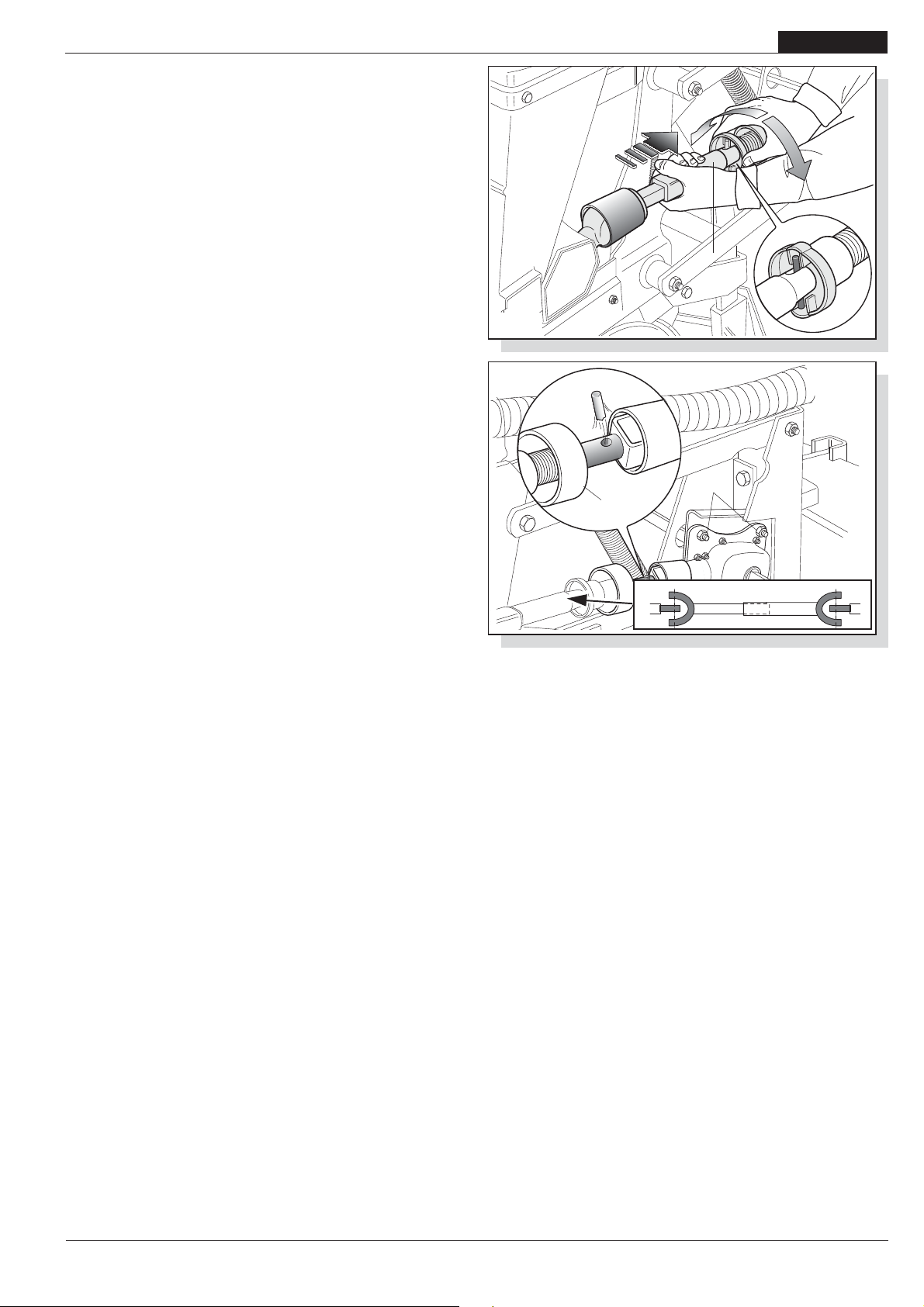
USE AND MAINTENANCE
3.13.3 SEEDER EXCLUSION
Switch off the tractor and remove the key;
Lift the single seeder from the ground in the following way:
- Hook the spring the position 1 (Fig. 15),
- Lift the seeder until it hooks on,
- Hook the spring the position 2 (Fig. 15);
Disconnect the seeder drive shaft (Fig. 28) as follows:
- Push the coupling sleeve and keep it pressed(1 Fig. 28) in the
direction shown by the arrow, press forward and at the same
time rotate the ring nut (2 Fig. 28) until it is free of the iron pin;
- Pull the sleeve back at the end of its run (1 Fig. 28).
- To render the drive operative again, push the sleeve forward
and lock the ring nut again against the iron pin.
ENGLISH
2
1
3.13.4 PLANTING UNIT TRANSMISSION
Each box has a safety pin (3 Fig. 29). When the rotation of the
seed disc comes under strain or stops due to the entering of
foreign bodies with the seeds (paper, string etc.), empty the seeds
from the container, check and clean the distributor, check the
disc pins and replace the safety pin.
IMPORTANT! Do not use metal pins.
CAUTION! Do not completely tighten the screws that hold the box
(4 Fig. 29); oscillation is expected.
fig. 28
fig. 29
3
4
5
Corretto-
Correct
-Korrector
cod. 19501381
-
49

ENGLISH
USE AND MAINTENANCE
3.14 ROW MARKER
The row marker is a device which tracers reference line on the
ground parallel to the direction of the tractor. When the tractor will
have finished its run and inverted its course, it will proceed with
one of the front wheels on the reference line (Fig. 30). At each
new passing the seeder will trace a reference line on the opposite
side of the previous one. Row marker arm inversion is activated
by the tractor’shydraulic distributor control. If requested it’s
possible to convert the row marker from hydraulic to mechanical.
3.14.1 HYDRAULIC ROW MARKER
The planting unit has a hydraulic row marker control device. The
plungers should be connected by their hydraulic pipes to the
ancillary hydraulic distributors of the tractor. Inside the hydraulic
cylinder boss there is a calibrated grub screw that could be
clogged by impurities in the oil. If there is malfunctioning, remove
the nipple and clean the hole of the calibrated grub screw, and
then put everything back paying attention to the direction of insertion
of the grub screw in the boss. On request, the hydraulic row
marker device can be fitted with a valve that alternately operates
the two arms.
In this case just one hydraulic tractor distributor is sufficient. When
the system is not in use, protect the quick coupling with its cap.
(Fig. 31).
fig. 30
D
L
C
DDD
Safety measures concerning the hydraulics:
1) When the hydraulic pipes are connected to the hydraulic
system of the tractor, make sure that the hydraulic systems
of the operating machine and the tractor are not under
pressure.
2) For hydraulic-type functional connections between the
tractor and operating machine, sockets and plugs must be
marked with colours, in order to prevent errors. It could be
dangerous if they were accidently confused.
3) The hydraulic system is under high pressure; due to the
risk of accident suitable auxiliary instruments should be
used when investigating possible leakage points.
System regulation:
The hydraulic systems provided come equipped with one-way
flow regulators (Fig. 32) which allow for the regulation of the
quantity of oil during opening or closing, depending on how the
regulators have been installed:
Flow from A to B, free;
Flow from B to A, choked (regulated).
o regulate, loosen the lock nut (1) and turn the knob (2). Once this
adjustment has been made, re-tighten the lock nut.
WARNING
Make sure that the result of this adjustment does not cause
the rising or descent speed to damage the structure itself.
Never exceed the maximum admissible pressure for the
hydraulic system.
fig. 31
(A)
1
(B)
2
fig. 32
50
-
cod. 19501381
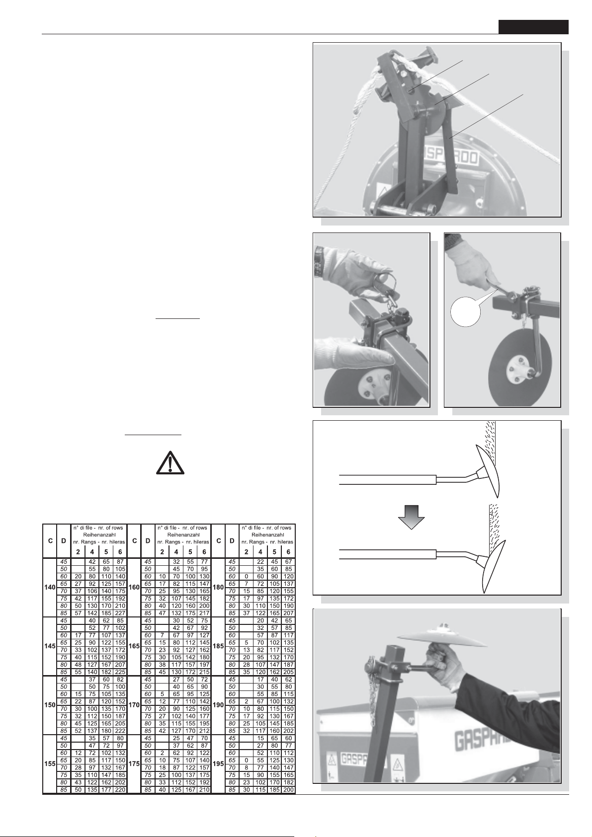
USE AND MAINTENANCE
3.14.2 MECHANICAL ROW MARKER AUTOMATIC CONTROL
If requested, the Manufacturer may supply a set for converting the
row marker from mechanical to hydraulic. The request must be
accompanied by the description of the type and model of the
seeder possessed. For the conversion all the particulars already
foreseen by the machine are re-used.
The row marker is enabled on the right or left of the tractor with an
automatic control (Fig. 33) triggered by the movement of the tractor
lifter. To do this it is enough to lift and lower the tractor lifter once.
Set up
If the pin (1 fig. 33) does not hook the disk (2) or vice versa it does
not unhook from it, adjust the height of the bars (3). When working,
the ropes must be pulled tight.
ENGLISH
1
2
3
3.14.3 ROW MARKER DISK ADJUSTMENT
Attach the disc holding sleeve (1 Fig. 34) onto the two arms of the
row marker, without over-tightening the nuts, insert the disc and
secure it in place by means of the snap pin. Using the table 2
shown, read the dis-tance (L Fig. 30) at which the disc is to draw
the reference line. Regulate the disc at the correct distance, tilt it
slightly and firmly tighten the nuts (Fig. 35). For normal soils the
correct working position of the disc is that shown in Fig. 36 ref. A;
for strong soils turn it over as shown in ref. B Fig. 36. For distances
not covered by the table, use the following rule:
L =
D (N+1) - C
2
where:
L= the distance between the outer most unit and the row marker.
D= the distance between the rows.
N= the number of units operating.
C= the tractorís front wheelbase
Example:
D = 75 cm; N = 8 units; C = 190 cm.
L =
75 (8+1) - 190 = 242,5 cm.
2
WARNING
When travelling by road, turn the row-marker discs inwards
towardsthe machine (Fig. 37).
Ta bl e 2
fig. 34
Avanzamento
Advancement
Avancement
fig. 33
1
nr 17
fig. 35
A
cod. 19501381
fig. 36
fig. 37
-
B
51

ENGLISH
USE AND MAINTENANCE
3.15 DISTRIBUTION OF CHEMICAL PRODUCTS
Fertilizers and insecticides are distrib-uted by means of special
dosers (1 Fig. 38) fitted under the corre-sponding hoppers. These
dosers can be adjusted by turning the knob (2 Fig. 38). Depending
on how the dosers are regulated please refer to the tables below
you can determine the quantity of fertilizer and insecticide needed
to cover a hectare of land.
HOPPER AND TANK FILLING
Hoppers and tanks can be filled by hand or using a lifter with a
capacity of at least 200 kg, which must be regularly approved by
the relative authorities. Remember that weights of more than 30
kg must either be lifted by more than one operator or the abovementioned lifter must be used following the instructions included
in the relative use and maintenance manual.
WARNING
- All fertilizer spreader tank loading and unloading operations
must be carried out with the planting unit at a standstill, on
the ground, with the frame open, with the hand brake on, with
the motor switched off and the starter key removed from the
control panel. Make sure that chemicals are kept out of
harm's way.
- All operations must be carried out by trained staff wearing
suitable protection (overalls, gloves, boots, masks etc) in a
clean, dust-free environment.
- Do not place any bags of fertilizer or any other object on the
fertilizer distributor container covers to avoid breaking them
or endangering property or persons.
- Load from the outer sides of the machine.
- When filling the seed, fertilizer and insecticide hoppers,
ensure that no foreign bodies (string, paper, etc.) enter them.
- The seeding machine can transport chemical substances.
Do not allow children, people, pets to come near the seeding
machine.
CAPACITY OF HOPPERS
fig. 38
fig. 39
2
19
NR -.........
1
1
1
1
Serbatoio
(mm)
500
850
A
1100
1500
250
B
250
A - Spandiconcime; B - Microcranulatore; (*) - Solo con serbatoi in metallo.
Materiale
Metallo Plastica
Capacit
Rialzo
(Litri)
(Litri)
92,5
157
203 97(*) 980(*)
277
15
16
Top
(Litri)
The plastic distributors do not require lubrication. On completion
of the work, the hopper should be carefully cleaned. This
particularly applies to the fertilizer hoppers. Unscrew the
discharge pipe caps remove any residual product (Fig. 39) and
wash thoroughly with water. Adhere to the ecological standards
applicable for the disposal of polluting liquids.
3.15.1REGULATING THE FERTILIZER INTERRING HOE
The fertilizer interring hoes operate parallel to the row being sown,
at a standard distance.
Before utilizing the seeder, ensure that this distance is suitable
for the type of fertilizer to be distributed and the quantity to be
distributed per hectare, so as to ensure that the crops will not
be damaged.
Should the distance not be suitable, distance the hoes further
from the row being sown. Also regulate the depth at which the
fertilizer is interred, by changing the height of the spring (Fig. 40).
After completing this operation, cut any extra off the length of the
tube so as to prevent the creation of folds which could obstruct
the flow of the fertilizer (Fig. 40).
fig. 40
fig. 41
52
-
cod. 19501381
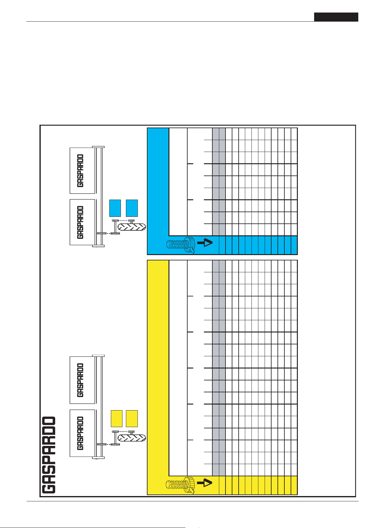
USE AND MAINTENANCE
ENGLISH
3.15.2 SPEEDY SET
The fertilizer spreader hopper can be equipped with the SPEEDY
SET (Fig. 41), which allows the MINIMAX volume batchers
(properly modified) to be adjusted on each hopper with just one
operation.
Regularly check that the sliding hatches are aligned.
The distribution table (19702951) suitable for this adjustment is
shown further on.
3.15.3 FERTILIZER DISTRIBUTOR - Table of distribution quantity
in kg/Ha
Posici n
- Reihenabstand
- Distancia entre las hileras
bersetzung d entrainemet
Transmision roue motrice
Trasmissione ruota motrice
- Prospectos de distribuci n
Transmission drive wheel
Z25
Z15
Position of distributor adjustment
Transmici n de la rueda motriz
Position reglage distributeur -
Row spacing
Interfila -
Distance entre les lignes
Abonadora
Z20
- D ngermengetabelle
Z20
Einstellung Einstellvorrchtung -
regulaci n distribuidor
R15 (*)
Posizione regolazione distributore -
5.00/80
CAUTION: the MINIMAX batcher, adjusted to the first positions
(B0÷C0 or 1÷1.5 with SPEEDY SET) may become clogged
because of the small opening, especially if fertilizers with irregular
grain size are used. If the quantity of fertilizer to be delivered
comes within the first positions (darkened lines on the table) get
in touch with the manufacturer. The figures given in the table are
approximate as the specific weight and size of the grains often
vary. In any case, always refer to the specific weight shown on
the product packaging; if this is not given, get in touch with the
manufacturer.
For specific weights that are different to those shown in the tables,
get in touch with Gaspardo Seminatrici S.p.A.
407 508 610 380 475 569 356 445 534
G-5
437 546 655 408 510 612 382 478 574
G-10
Les valeurs indiquØes
The chart values are only approximate, since the specific
. - Los valores de la tabla son
.
20%
.
.
20%
.
- Spezifisches Gewicht
- Peso especifico : Kg/dm‡
Specific weight
Poids specifique
Peso specifico -
64 80 96 60 75 89 56 70 84
B-0
94 118 141 88 110 132 82 103 124
B-5
124 155 187 116 145 174 109 136 163
C-0
158 197 237 147 184 221 138 173 207
C-5
188 235 282 176 220 264 165 206 247
D-0
218 273 328 204 255 306 191 239 287
D-5
249 311 373 232 290 348 218 272 326
E-0
282 353 424 264 329 395 247 309 371
E-5
313 391 469 292 365 438 274 342 410
F-0
343 429 514 320 400 480 300 375 450
F-5
376 471 565 351 439 527 329 412 494
G-0
Cod. 19700821
D ngerstreuer
- Tableaux de distribution
- Tabella di distribuzione
- Distribution table
Fertilizer
Espandeur d’engrais
Spandiconcime
GASPARDO Seminatrici S.p.A.
Z20
Trasmissione ruota motrice
Transmission drive wheel
Z30
Z20
bersetzung d entrainemet
Transmision roue motrice
Transmici n de la rueda motriz
Z10
5.00/80
R15 (*)
Position reglage distributeur
- Reihenabstand
- Distancia entre las hileras
Einstellung Einstellvorrchtung -
Row spacing
Interfila -
Distance entre les lignes
Position of distributor adjustment -
- Spezifisches Gewicht
- Peso especifico : Kg/dm‡
Specific weight
Poids specifique
Peso specifico -
45 cm 50 cm 60 cm 70 cm 75 cm 80 cm 70 cm 75 cm 80 cm
Posizione regolazione distributore -
Posici n regulaci n distribuidor
0,8 1 1,2 0,8 1 1,2 0,8 1 1,2 0,8 1 1,2 0,8 1 1,2 0,8 1 1,2 0,8 1 1,2 0,8 1 1,2 0,8 1 1,2
55 69 83 50 62 75 41 52 62 35 44 53 33 41 50 31 39 47
B-0
81 102 122 73 92 110 61 76 92 52 65 78 49 61 73 46 57 69
B-5
107 134 161 97 121 145 81 101 121 69 86 104 64 81 97 60 76 91
C-0
137 171 205 123 154 184 102 128 154 88 110 132 82 102 123 77 96 115
C-5
163 203 244 146 183 220 122 153 183 105 131 157 98 122 146 92 114 137
D-0
189 236 283 170 212 255 142 177 212 121 152 182 113 142 170 106 133 159
D-5
215 269 322 193 242 290 161 202 242 138 173 207 129 161 193 121 151 181
E-0
244 305 366 220 275 329 183 229 275 157 196 235 146 183 220 137 172 206
E-5
270 338 405 243 304 365 203 253 304 174 217 261 162 203 243 152 190 228
F-0
296 370 444 267 333 400 222 278 333 190 238 286 178 222 267 167 208 250
F-5
325 407 488 293 366 439 244 305 366 209 261 314 195 244 293 183 229 275
G-0
351 439 527 316 395 475 264 330 395 226 282 339 211 264 316 198 247 297
G-5
378 472 566 340 425 510 283 354 425 243 303 364 227 283 340 212 266 319
G-10
die Mengen der Tabelle um 20% vermindern.
With 6.50/80 R15 wheels decrease distribution quantity by 4% . With 7.50 R16 wheels decrease by 20%
)
*
(
disminuir los mismo del
7.50 R16
. Con ruedas
4%
disminuir los valores de la tabla del
6.50/80 R15
Avec roues de 6.50/80 R15 diminuer les donnØes du tableau de 4% . Avec roues de 7.50 R16 diminuer de 20%
) Con ruedas
)
*
*
(
(*) Mit Bereifung 6.50/80 R15 die Mengen der Tabelle um 4% vermindern. Mit Bereifung 7.50 R16
(
diminuire i valori della tabella del
7.50 R16
. Con ruote
4%
. - Die Tabellenwerte sind Richtwerte, da das spezifische Gewicht und die Gr e der K rner oft unterschiedlich sind. -
las dimensiones de los granos son, generalmente, diferentes.
diminuire i valori della tabella del
6.50/80 R15
) Con ruote da
*
(
I valori della tabella costituiscono solo valori indicativi, in quanto il peso specifico e la grandezza dei granelli sono spesso diversi. -
weight and the size of the granules often differ
sur le tableau de rØglage costituent simplement des valeurs donnØes titre indicatif car le poids spØcifique et la grandeur des grains sont souvement diffØrents
slo indicativos, ya que el peso espec fico y
cod. 19501381
-
53

ENGLISH
3.15.4 SPEEDY SET
USE AND MAINTENANCE
54
-
cod. 19501381

USE AND MAINTENANCE
3.15.5 MICROGRANULATOR - Table of distribution quantity in Kg/
Ha
ENGLISH
cod. 19501381
-
55
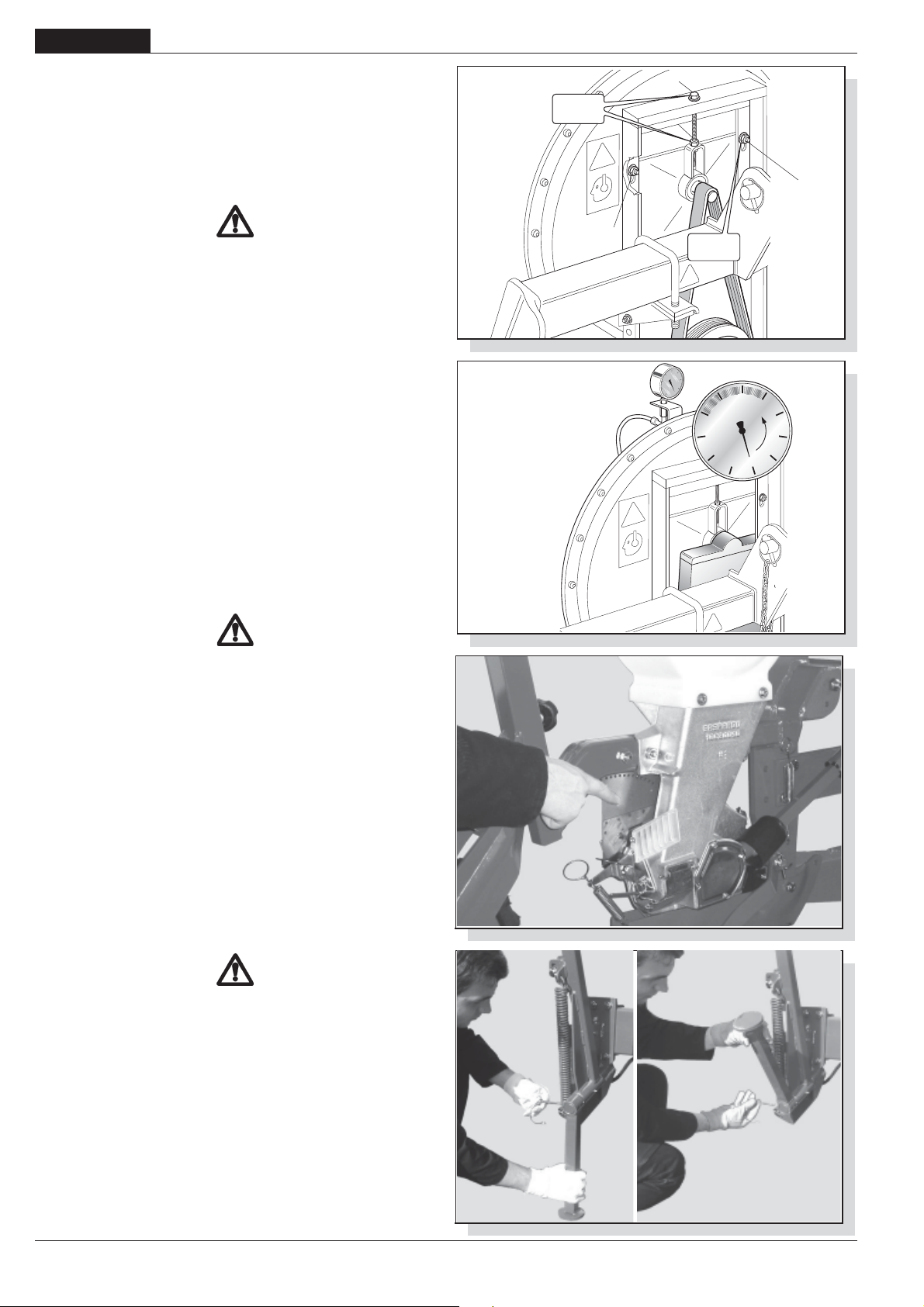
ENGLISH
USE AND MAINTENANCE
3.16 VACUUM PUMP
The aspirator (Fig. 42) creates a vacuum inside the distributors,
so that the seeds are aspirated onto the holes in the plate. The
tensioning and good condition of the belt are therefore of vital
importance to ensure the good for the good operation of the
aspirator and, hence, the success of the sowing.
The belt is correctly tensioned when it does not yield under the
pressure of a hand.
WARNING
Make sure that the universal joint is disconnected from the
power take-off before carrying out the following operations:
Belt checking procedure:
- Remove the protective housing
- Loosen the 4 screws (1 Fig. 42)
- Loosen the nut (2 Fig. 42)
- If worn, replace the belt.
- Tension the belt by tightening the screws (3 Fig. 42).
- Tighten the bolts loosened before and close the casing.
Vacuometer
The vacuometer (Fig. 43) a the vacuum measuring device. The
one supplied shows aspiration values ranging from -0 to -100
mbar. The average approximate aspiration values for large seeds
are: 60 to -70 mbar for small seeds: -40 to -50 mbar.
NR -
17
3
2
1
1
NR -
-70
-80
19
-60
-90
-100
-50
Mbar
fig. 42
-40
-30
-20
-10
0
Comply with the number of rpm recommended for the power
take-off.
3.17 PREPARING FOR SEEDING
The planting unit must be correctly adjusted in the field.
DANGER
Carefully follow the instructions below and perform the
operations in the order they are listed:
- From the driverís seat of the tractor, raise the seeder;
- Operate the power take-off at 540 rpm;
- Using the gear lever, put the tractor engine into neutral;
- Brake the tractor and if necessary, secure it with wooden blocks
sized according to the size of the wheels;
- Ensure that no-one can approach the tractor driver's seat;
- Check that all the drive shafts are properly engaged.
- Carefully check moving parts, dri-ving parts and seed
distribution.
- Load the seed hoppers: remember that weights of more than
30 kg must either be lifted by more than one operator or the
above-mentioned mechanical lifter must be used following the
instructions included in the relative use and maintenance
manual.
fig. 43
fig. 44
WARNING
All operations must be carried out by trained staff wearing suitable
protection (overalls, gloves, boots, masks etc) in a clean, dustfree environment. When loading the hoppers with seed, and the
tanks with fertilizer or insecticide, make sure that no foreign bodies
(string, paper bags, etc) get into the tanks.
- Manually turn the seeder gear drive wheel in the direction in
which the machine is moving;
- Adjust the selector and control through the transparent grate
(Fig. 44) that the plate is only holding one seed per hole;
- From the "seed chart" on page 47 the number of seeds required
can be determined in advance.
56
-
fig. 45
cod. 19501381
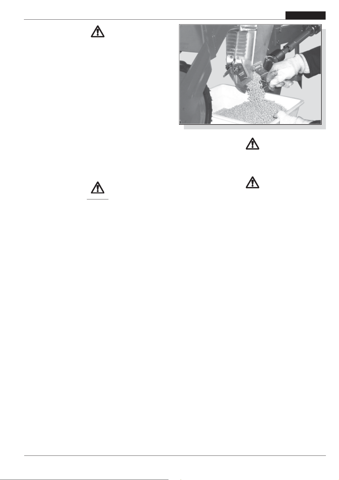
USE AND MAINTENANCE
CAUTION
Remove and overturn the supporting feet (Fig. 45).
- Proceed with seeding: after a few metres check to ensure that
the distributors are sowing one seed at a time.
At the end of seeding, discharge the remaining seeds through
the distribu-tor door (Fig. 46).
3.18 DURING SEEDING
- Each drive shaft has a torque limiter with a sound alarm (5 Fig.
29) that, when the pin breaks (3 Fig. 29), signals the anomaly
or fault that has occurred in the seed distributor. If this happens,
stop at once and put the fault right, remove the broken pin and
put in a new one (use the tool supplied for this).
- At the end of each run, while reversing, always keep the power
take-off running at sufficient revs. per minute to ensure that the
seeds remain attached to the distributor plates.
- During seeding check the seed distribution frequently and, if
irregular, adjust the selector.
- If there is a loss or decrease of suction, check that the pipes
are not damaged or clogged; if so, replace or clean them,
checking the aspirator belt also.
ENGLISH
fig. 46
DANGER
The seeding machine can transport chemical substances. Do
not allow children, people, pets to come
near the seeding machine.
CAUTION
- The shape, dimensions and material of the drive shaft elastic
pins have been selected for reasons of safety. The use of
non-original or more resistant pins could cause serious damage to the seeding machine.
- Start the power take-off gradually; sudden movements are
harmful to the aspirator belt.
- Avoid curves with the machine grounded, and do not work in
reverse. Always lift it when changing direction or reversing.
- Do not work with the power take-off synchronized with the
wheels.
- Do not exeed the number of revolutions per minute indicated
on the power take-off.
- Never push the tractor to maximum revs.
- Maintain a seed planting speed that is compatible with the
type and preparation of the soil in order to avoid breakages
or damage.
- Low the seeding machine while the tractor is moving so as
not to clog or damage the coulter parts. For the same reason
it is unadvisable to manoeuvre in reverse with the seeder
lowered.
- When filling the seed, fertilizer and insecticide hoppers,
ensure that no foreign bodies (string, paper, etc.) enter them.
WARNING
Do not place any bags of fertilizer or any other object on the
fertilizer distributor container covers to avoid breaking them
or endangering property or persons. Load from the outer sides
of the machine.
It is forbidden to come near the containers of the chemical
substances or to open them when the seeding machine is
operating or about to operate.
cod. 19501381
-
57

ENGLISH
USE AND MAINTENANCE
3.19 PREPARATION
In all the models the seeding elements are connected
independently to the frame by means of hinged parallelogram
mechanisms, though with some particular features depending
on the type of seed to be distributed and the characteristics of the
ground being worked on.
a) seeding elements for deep seed planting
two different types of element are available for the medium depth
equipment in relation to the roughness of the seed planting bed:
- for finely prepared ground it is advisable to use cutter/planter
shoes with sod breaker and press wheels (fig. 47);
- for rougher ground and where there are residues, it is more
advisable to use double disc tools placed upstream of the
cutter/planter shoes followed by press wheels (fig. 48);
For different soils, 3 different types of seed covering element are
available (fig. 49):
farmflex wheel (Ø=370 mm) recommended for damp and
1)
sandy soils;
2) rubber "V" wheels more suitable for damp and "difficult" soils.
3) iron "V" wheels suitable for dry, medium grade soils;
b) seeding elements for surface seed planting
The seeding element for surface seed planting has a standard
equalizer with rubber wheels: the one at the front is a "sod crusher"
with a rounded shape (having Ø=280 mm), followed by the seed
pressing wheel, also in rubber, with independent seed coverers
(fig. 50).
For different soils, 3 different types of seed covering element are
available (fig. 51):
1) concave rubber wheel (Ø=290 mm) specifically for beet;
2) rubber "V" wheels suitable for damp and difficult soils;
3) farmflex wheel (Ø=370 mm) suitable for damp and sandy
soils.
fig. 47
fig. 48
fig. 49
fig. 50
fig. 51
58
1
2
3
-
1
2
3
cod. 19501381

USE AND MAINTENANCE
ENGLISH
ADJUSTMENT OF REAR COMPRESSION WHEELS
The rear equipment of the seeding elements is very important in
quality seed planting.
These elements are crucial for the seed planting depth and the
covering of the seeds after dropping.
RUOTA FARMFLEX 370 mm
Semine medio profonde
(mais, girasole, soia)
max 10 cm
RUOTA FARMFLEX 370 mm
Semine superficiali
(barbabietole)
They should therefore be adjusted correctly, according to the type
of seed planting and the type of soil, by varying the position of the
rear wheels on their support as shown in the following diagram.
max 7 cm
max 3,5 cm
max 3,5 cm
max 5 cm
RUOTA IN GOMMA
A PROFILO CONCAVO 290 mm
Semine superficiali
(barbabietole)
max 5 cm
RUOTE A V IN GOMMA
1 - 2
max 4,5 cm
max 14 cm
cod. 19501381
-
max 6,5 cm
max 11 cm
59

ENGLISH
USE AND MAINTENANCE
4.0 MAINTENANCE
Here follows a list of various maintenance operations to be carried
out periodically. Lowered operating costs and a longer lasting
seeding machine depend, among others, on the methodical and
constant observation of these rules. The snap hooking system,
practical and safe allows to lift the seeder for maintenance and
inspection (Fig. 15).
CAUTION
- The maintenance periods listed in this booklet are only
indicative and are for on normal conditions on use, therefore
be varied depending the kind of service, the more or less
dusty surroundings, seasonal factors, etc. For more
serious conditions of service, maintenance will logically
be done more often.
- Before injecting grease, the nipples must be cleaned to
avoid mud, dust and foreign bodies from mixing with the
grease, otherwise they will reduce or even annul the effect
of the lubrication.
ATTENTION
- Always keep oils and grease out of reach of children.
- Always read carefully the instructions and precautions shown
on the containers and on the product safety charts.
- Avoid skin-contact
- After use wash the equipment thoroughly.
- Treat the used oils and polluting liquids in conformity with
the laws in force.
4.0.1 WHEN THE MACHINE IS NEW
- After the first eight hours of work, check that all the bolts are still
tight.
4.0.2 AT THE BIGINNING OF THE SEEDING SEASON
- Operate the empty seeding machine, the air-flow frees the pipes
from condensation and removes eventual impurities.
fig. 52
3
1
6
4
2
5
60
-
cod. 19501381

USE AND MAINTENANCE
ENGLISH
4.0.3 EVERY EIGHT HOURS OF WORK
- Grease the universal joint spiders.
- Grease the row-marker disk pivot (1 fig. 52).
- If iron “V” wheels are fitted, grease the hubs (3 fig. 52).
- Check the fan-belt tension (Fig. 42).
4.0.4 EVERY FIFTY HOURS OF WORK
- Inspect the state of the perforated disks; if some pegs are
missing or bent, replace the disk with an original spare; if there
are circular grooves on the disks they must not be deeper than
1/3 of the disk thickness.
- Clean the inside of the seed distributor with water and petrol
(gasoline); replace the cover seal if necessary.
- Grease the row-marker arm pivot (6 fig. 52)
4.0.5 EVERY SIX MONTHS
- Oil the height adjust bolt (2 fig. 52).
- Grease the drive wheel oscillating bearings (4 fig. 52).
- Grease the bevel gear pair of the Cardan shaft (5 fig. 52).
4.0.6 ETTING ASIDE
At the end of the season , or if a long period of rest is for seen it is
advisable:
- Wash the equipment with a lot of water, especially the tanks of
the chemical substances, and than dry them.
- Carefully check worn or damaged parts and replace if
necessary.
- Adjust the depressor belt and replace if necessary.
- Tighten all screws and bolts.
- Grease the drive chains, oil all the drive chains, spread lubricant
on all the parts not painted.
- Protect the equipment with a (nylon) cover .
- Then put it in a dry place, do not move it and where it is out of
reach of unauthorized people.
If these operations are done carefully, it will be to the total
advantage of the user because when work is recommenced, he
will find the equipment in perfect conditions.
4.0.7 RECOMMENDED LUBRICANTS
- For lubrication in general, we advise: OLIO AGIP BLASIA 460
SAE 85W/140 or equivalent, for specification see last cover
page.
- For all greasing points we advise: GRASSO AGIP GR MU EP 2
or equivalent for specifications see last cover page.
5.0 DEMOLITION AND DISPOSAL
This operation is to be carried out by the customer.
Before demolishing the machine, you are advised to carefully
check its physical condition and ascertain whether there are any
parts of the structure that may be susceptible to structural collapse
or breakage during demolition.
The customer should operate in compliance with the environment
protection laws in force in his/her country.
CAUTION
The machine demolition operations should be carried out by
skilled personnel only, equipped with suitable protective
clothing (safety footwear and gloves) and auxiliary tools and
equipment.
CAUTION
All the disassembly operations for demolition should be carried
out with the machine stopped and detached from the tractor.
Before demolishing the machine, you are advised to render
harmless all the parts that may be a source of danger and
therefore:
- scrap the structure using specialized firms,
- remove any electrical apparatus according to the laws in force,
- collect oils and greases separately, to be disposed of through
specialized firms, in accordance with the regulations of the
country in which the machine was used.
When the machine is demolished the CE mark should be
destroyed together with this manual.
6.0 SUPPLY
Current supplied equipment:
- A booklet for use and maintenance;
- A booklet for spare parts;
- Cardan shaft;
- With pulley for tractors with power take-off at 540 rpm.
- A series of seeding disks;
- Row marker;
- N.4 gears (2 fitted) for wheel-gear drive;
- Pin remover;
- N.10 seeder universal joint limiter safety pins
- N.4 gears (2 fitted) for the manure spreader drive and/or
granulate distribution (if supplied with the machine);
- Optical signal set (rear lights).
cod. 19501381
Optional equipment. The seeding machine may be equipped
with:
- Double disk furrow opener version;
- Rocker version;
- With electronic hectare counter;
- With seed control monitor;
- With fixed sod-breaker;
- With mechanical or hydraulic row-marker;
- With 370 mm rubber compression wheels;
- With iron or rubber “V” compression wheel;
- With 290 mm rubber concave compression wheel complete
with seed press wheel;
- With 6.50/80 x 15 driving wheels;
- With free wheel double drive;
- With double pair trace breaker;
- With pulley for tractors with power take-off at 1000 rpm.
Finally, we remind you that the manufacturer is always available
for any and all necessary assistance and spares.
-
61

Notes
62
-
cod. 19501381

Notes
cod. 19501381
-
63

64
-
cod. 19501381

DEUTSCH
1.0 VORWORT
Dieses Heft beschreibt die Betriebs- und Wartungsanleitungen.
Das vorliegende Heft ist integrierender Teil des Produkts und
muß während der Gesamtlebensdauer der Maschine zwecks
Ratnahme sicher aufbewahrt werden.
Der Kunde hat das Personal bezüglich der Unfallgefahr, der für
die Sicherheit des Bedieners vorgesehenen
Schutzvorrichtungen, der durch den Schallpegel der Maschine
entstehenden Gefahren sowie bezüglich der von den
internationalen Richtlinien und dem Gesetzgeber des Landes,
in dem die Maschine eingesetzt wird, vorgesehenen allgemeinen
Unfallverhütungsvorschriften zu unterrichten. Auf jeden Fall darf
die Maschine nur von qualifiziertem Personal verwendet werden,
das die in dem vorliegenden Handbuch enthaltenen technischen
Anleitungen und Unfallverhütungsvorschriften genau zu befolgen
hat. Es ist Aufgabe des Anwenders dafür Sorge zu tragen, dass
die Maschine nur unter derartigen Bedingungen eingesetzt wird,
dass die Sicherheit von Personen, Tieren und Sachen
gewährleistet ist.
Das Produkt entspricht den folgenden EG-Normen:
- 98/37 EG Maschinenrichtlinie, die die Richtlinien 89/392 EG,
91/368 EG, 94/44 EG und 93/68 EG ersetzt und einschließt.
- 89/336 EG (betreffend die Harmonisierung der Gesetzgebung
der Mitgliedsstaaten bezüglich des Elektromaterials, das für
den Einsatz innerhalb gewisser Spannungsgrenzen
vorgesehen ist).
Zum Anpassen der Maschine wurden folgende Normen
angewandt:
- EN 292-1:1992 (Sicherheit der Maschine) Grundlegende
Konzepte, allgemeine Entwicklungsprinzipien. Begriffe,
grundlegende Methodik.
- EN 292-1 A/1:1992
- EN 292-2:1992 (Sicherheit der Maschine) Grundlegende
Konzepte, allgemeine Entwicklungsprinzipien. Technische
Spezifikationen und Prinzipien.
- EN 294:1993 (Sicherheit der Maschine) Sicherheitsabstand,
damit die oberen Gliedmaßen nicht in gefährliche Bereiche
gelangen
- EN 982:1997 (Sicherheit der Maschine)
Sicherheitsvoraussetzungen bezüglich Systemen und deren
Komponenten für ölhydraulische und pneumatische Antriebe.
- EN 1553:1999 (Landwirtschaftsmaschinen) Selbstfahrende,
geschleppte, halbgeschleppte oder gefahrene Landwirtschaftsmaschinen - Allgemeine Sicherheitsanforderungen.
- pr EN 144045 (Sämaschinen - Sicherheit) Unterlage CEN/TC
144 WG 3 Nr.347 - Ausgabe Mai 2000.
1.1 BESCHREIBUNG DER SÄMASCHINE
Dieses landwirtschaftliche Gerät, “Pneumatische Sämaschine
SP” genannt, kann nur durch die Gelenkwelle betrieben werden,
die mit der Zapfwelle eines mit Kraftheber ausgestatteten
Landwirtschafts-schleppers mit universeller DreipunkteKupplung verbunden wird. Das Gerät ist besonders zur
Präzisionsaussaat geeignet,ist vielseitig einsetzbar und dient
für jeden Saatguttyp auf Ackerböden. Die Sämaschine ist
pneumatisch betrieben und kann mit verschiedenem Zubehör
ausgestattet werden, z.B. Düngerstreuer, Mikro-granulatstreuer
und zusätzliche Aussaatelemente. In der “SP” wurde das
Grundkonzept “Modulationsfähigkeit” entwickelt und mit dem der
“Einfachheit” verbunden, mit Hinblick sowohl auf Konstruktion
als auf den praktischen Gebrauch.
ACHTUNG
Die Sämaschine ist ausschliesslich zur Aussaat auf
Ackerboden geeignet. Es wird eine Arbeitsgeschwindigkeit von
6÷8 km/h empfohlen. Der Straßentransport der Sämaschine
muss mit leeren Behältern und Trichtern bei einer
Höchstgeschwindigkeit von 25 km/h erfolgen. Jeder andere
Gebrauch, der von den hier beschriebenen Anleitungen
abweicht, kann die Maschine beschädigen und stellt für den
Verbraucher grosse Gefahr dar.
Die richtige Betriebsweise des Geräts hängt vom korrekten
Gebrauch und der regelmässigen Wartung ab. Das hier
beschriebenen Anleitungen müssen daher zur Verhütung jeder
Art von Störung, die den richtigen Betrieb und die Lebensdauer
der Maschine beeinschränken könnte, absolut beachtet werden.
Bei Nicht-Beachtung dieser Bestimmungen und im Fall von
Nachlässigkeit lehnt der Hersteller jegliche Haftung ab. Der
Hersteller steht auf jeden Fall für sofortige und sorgfältige
technische Beihilfe und für alles, was zum Erreichen der besten
Betriebsweise und Höchstleistung des Geräts beitragen kann
kann, zur vollen Verfügung.
1.2 GARANTIE
- Bei Auslieferung sicherstellen, daß das Gerät keine
Transportschäden aufweist und das Zubehör unbeschädigt
und vollständig ist.
- Etwaige Reklamationen müssen innerhalb von 8 Tagen ab
Erhalt schriftlich eingereicht werden.
- Der Käufer kann seine Garantieansprüche nur geltend machen,
wenn er die im Liefervertrag aufgeführten Garantiebedingungen
eingehalten hat.
- Die Garantie erstreckt sich auf ein Jahr ab Lieferdatum des
Geräts gegen jeglichen Materialfehler.
- Die Garantie schliesst die Kosten für Arbeitskraft und Spedition
nicht ein (das Material reist auf Gefahr des Empfängers)
- Von der Garantie sind Schäden an Personen oder
Gegenständen ausgeschlossen.
- Die Garantie begrenzt sich auf die Reparatur oder den
kostenlosen Ersatz des fehlerhaften Teils, laut Anweisungen
des Herstellers.
Händler oder Verbraucher können vom Hersteller keinen Ersatz
für ihre eventuellen Schäden (Kosten für Arbeitskraft, Transport,
mangelhafte Arbeit, direkte oder indirekte Unfälle, kein
Ernteertrag, usw.) verlangen.
1.2.1 VERFALL DES GARANTIEANSPRUCHS
Über das im Liefervertrag beschrieb-ene hinaus, verfällt die
Garantie:
- Wenn die in der Tabelle der technischen Daten angegebenen
Grenzen überschritten werden.
- Wenn die in diesem Heft beschriebenen Anleitungen nicht
genauestens befolgt werden.
- Bei falschem Gebrauch, mangelhafter Wartung und im Fall
von anderen durch den Kunden verursachten Fehlern.
- Wenn ohne schriftliche Bevollmächti-gung des Herstelles
Veränderungen durchgeführt werden oder keine
Originalersatzteile verwendet werden.
cod. 19501381
-
65

DEUTSCH
peg
)
GEBRAUCH UND WARTUNG
1.3 TECHNISCHE DATEN U.M.
Rahmenbreite
Reihenabstand
m
feet
cm
inch
Inhalt des Saatgutbeh lters l.
Inhalt des D ngerbeh lters l.
Zapfwelle U/Min.
Kraftbedard
Gewicht (*)
Messung des unbelasten
lm
els
HP
KW
Kg
lb
Lpam (A)
Lwa (A
4 Reihn.
cm. 75
2,50
8-2"
75
29
320 320 560 320
60
44
550
1210
5 Reihn.
cm. 75
3,20
10-5"
60
23
70
51
615
1353
92,3
109,7
32
540
6 Reihn.
cm. 75
4,20
14"
75
29
90
66
662
1456
6 Reihn.
cm. 45
2,50
8-2"
45
17
70
51
740
1628
(*) Ohne D ngerstreuer und Mikrogranulatstreuer.
Die Angaben bezüglich der technischen Daten und Modelle sind unverbindlich. Der Hersteller behält sich das Recht vor, diese
Angaben ohne Vorankündigung zu ändern.
1.4 IDENTIFIZIERUNG
Jedes einzelne Gerät ist mit einem Identifizierungsschild (15
Abb. 2) ausgestattet, mit folgenden Angaben:
- Firmenzeichen des CE;
- Firmenzeichen des Herstellers;
- Name, Bezeichnung und Adresse des Herstellers;
- Modell der Maschine;
- Serien-Nummer der Maschine;
- Baujahr;
- Gewicht, in Kilogramm.
Diese Daten immer angeben, wenn Kundendienst oder
Ersatzteile erforderlich sind.
Das Maschinengewicht kann dem Identifizierungsschild (15 Abb.
2) entnommen werden. Zum Ausrichten der Maschine das Seil
spannen.Die Anschlusspunkte sind durch das graphische
“Haken”-Zeichen (9 Abb. 3) gekennzeichnet. Bei Maschinen bis
4 Reihen, in den Punkten A, C und D einhaken. Bei Maschinen
mit mehr als 4 Reihen in den Punkten A, B, C, D und E einhaken.
A
1.5 FORTBEWEGUNG
Falls die Maschine transportiert werden muss, muss sie an den
dazu bestimmten Anschlusspunkten durch geeigneten Aufzug
oder Kran mit ausreichender Tragkraft gehoben werden. Diese
gefährliche Arbeit muss absolut durch geschultes und haftendes
Personal ausgeführt werden.
BCDE
fig. 1
66
-
cod. 19501381

SÄAGGREGAT
MAIS - SONNENBLUMEN - SOJA
SÄAGGREGAT
RÜBEN
GEBRAUCH UND WARTUNG
6
7
8
DEUTSCH
4
5
fig. 2
1.6 ZUSAMMENFASSEND
1 Spurreisserscheibe
2 Düngerbehälter
3 Gebläse
4 Vakuummeter
5 Luftverteiler
6 Saatgutbehälter
7 Säelementhöhenregler
8 Druckrolle
9 Düngerstreuer Antriebsrad
10 Säapparat
11 Säscharenreisser
12 Gelenkwelle für Säelementantrieb
13 Stützfuß
14 Rahmen
15 Identifizierungsschild
16 Düngerstreuregler (Minimax)
17 Spurreissersteuerung
18 Gelenkwellenkupplung
19 Gelenkwellen
20 Schollenabweiser
21 Samenabdecker
15
20
1
23
13 14
21
16 1718 19
11
9
12
10
cod. 19501381
-
67
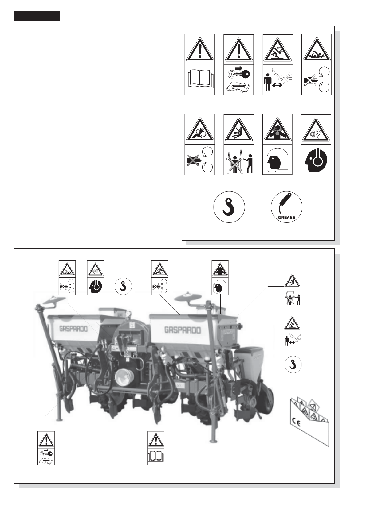
DEUTSCH
GEBRAUCH UND WARTUNG
1.7 WARNSIGNALE
Die in Abb. 3 beschriebenen Signale sind an der Maschine
angebracht. Sauber halten und wechseln, falls sie abfallen oder
unleserlich werden. Die Beschreibung aufmerksam lesen und
die Bedeutung der Signale gut dem Gedächtnis einprägen.
1) Vor Arbeitsanfang die Anleitungen aufmerksam lesen.
2) Vor Wartungsarbeiten die Maschine abstellen und die
Anleitungen lesen.
3) Quetschgefahr bei Öffnung. Sicherheitsabstand von der
Maschinehalten.
4) Gefahr, von der laufenden Gelenkwelle erfasst zu werden.
Von laufenden Teilen Abstand halten.
5) Einfanggefahr. Von laufenden Teilen Abstand halten.
6) Quetschgefahr bei Verschliessen. Den nötigen Abstand von
der Maschine halten.
7) Geeignete Schutzkleidung bei Gebrauch von Giftstoffen
benützen.
8) Hoher Lärmpegel. Geeigneten Lärmschutz benützen.
9)Kupplungspunkte zur Hebung.
10)Schmierstellen
1234
56
910
78
fig. 2
68
fig. 3
-
DECALCOMANIE AVVERTIMENTO
Cod. 89900500
WARNING STICKERS
ABZIEHBILDER MIT WARNHINWEISEN
DECALCOMANIE
CALCOMANIAS
cod. 19501381
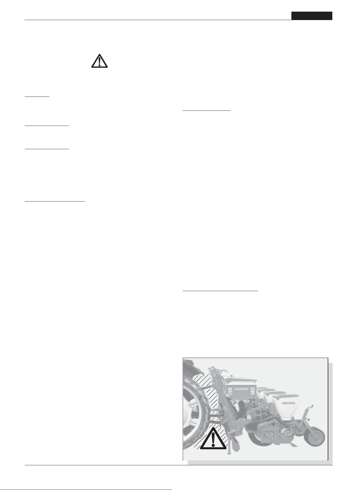
GEBRAUCH UND WARTUNG
DEUTSCH
2.0 SICHERHEITS- UND UNFALLVERHÜTUNGSBESTIMMUNGEN
Das Gefahrsignals in diesem Heft besonders beachten.
Die Gefahrsignale haben drei Niveaus:
GEFAHR: Dieses Signal meldet, daß bei nicht richtiger
Durchführung der beschriebenen Arbeiten schwere Verletzungsund Todesgefahr oder Langzeitrisikos für die Gesundheit
entstehen.
ACHTUNG: Dieses Signal meldet, daß bei nicht richtiger
Durchführung der beschriebenen Arbeiten schwere Verletzungsund Todesgefahr oder Langzeitrisikos für die Gesundheit
entstehen können.
VORSICHT: Dieses Signal meldet, daß bei nicht richtiger
Durchführung der beschriebenen Arbeiten Maschinen-schäden
entstehen können.
Vor dem ersten Gebrauch der Maschine alle Anweisungen
aufmerksam lesen, im Zweifelsfall wenden Sie sich direkt an
die Techniker des Vertragshändlers der Herstellerfirma. Die
Herstellerfirma lehnt jegliche Haftung ab, falls die hier folgend
beschriebenen Sicherheits- und
Unfallverhütungsbestimmungen nicht beachtet werden.
Allgemeine Vorschriften
1) Auf die Gefahrzeichen achten, die in diesem Heft aufgeführt
und an der Sämaschine angebracht sind.
2) Die an der Maschine angebrachten Aufkleber mit den
Hinweisen geben in knapper Form Anweisungen zur
Vermeidung von Unfällen.
3) Mit Hilfe der Anweisungen sind die Sicherheits- und
Unfallverhütungsvorschriften genauestens zu beachten.
4) Niemals sich bewegende Teile anfassen.
5) Eingriffe und Einstellungen am Gerät dürfen nur bei
abgestelltem Motor und blockiertem Schlepper durchgeführt
werden.
6) Es ist strengstens verboten, Personen oder Tiere auf der
Maschine zu befördern.
7) Es ist strengstens verboten, den Schlepper bei
angekuppelter Maschine von Personal ohne Führerschein,
von unerfahrenem Personal oder von Personal, das sich
nicht in einwandfreiem Gesundheitszustand befindet, führen
zu lassen.
8) Vor Inbetriebnahme des Schleppers und der Maschine selbst
alle Sicherheitvorrichtungen für Transport und Gebrauch auf
ihre Unversehrtheit prüfen.
9) Vor der Inbetriebnahme der Maschine ist sicherzustellen,
daß sich im Wirkungskreis derselben keine Personen,
insbesondere Kinder und Haustiere aufhalten und daß man
über eine optimale Sicht verfügt.
10) Geeignete Arbeitskleidung tragen. Flatternde
Kleidungsstücke sind absolut zu vermeiden, da sich diese
in den sich drehenden und bewegenden Teilen der Maschine
verfangen können.
11) Vor Arbeitsbeginn hat man sich mit den Steuervorrichtungen
und deren Funktionen vertraut zu machen.
12) Die Arbeit mit der Maschine erst beginnen, wenn alle
Schutzvorrichtungen vollständig, angebracht und in
Sicherheitsposition sind.
13) Es ist strengstens verboten, sich in Bereichen aufzuhalten,
die in der Nähe sich bewegender Maschinenteile liegen.
14) Der Gebrauch der Maschine ohne Schutzvorrichtungen und
ohne Behälterabdeckungen ist streng verboten.
15) Vor dem Verlassen des Schleppers das an die
Hubvorrichtung angekuppelte Gerät absenken, den Motor
abstellen, die Feststellbremse ziehen und den Zündschlüssel
aus der Steuertafel ziehen. Sicherstellen, daß sich niemand
den Chemikalien nähern kann.
16) Nie den Fahrerplatz verlassen, wenn der Schlepper in Betrieb
ist.
17) Vor der Inbetriebnahme des Geräts prüfen, daß die
Stützfüsse unter der Sämaschine entfernt wurden, die richtige
Montage und Einstellung der Sämaschine prüfen; den
perfekten Maschinenzustand kontrollieren und sicherstellen,
daß die Verschleißteile sich in gutem Zustand befinden.
18) Vor dem Auskuppeln der Vorrichtung aus dem Drei-PunktAnschluß ist der Steuerhebel des Hubwerks in die
Sperrposition zu bringen und es sind die Stützfüsse
abzusenken.
19) Immer bei guter Sicht arbeiten.
20) Alle Tätigkeiten sind in sauberer, nicht staubiger Umgebung
von erfahrenem, mit Schutzhand-schuhen ausgestattetem
Fachpersonal durchzuführen.
Schlepperanschluß
21) Die Maschine mittels der dazu bestimmten, den Normen
entsprechenden Hubvorrichtung wie vorgesehen an einen
Schlepper mit geeigneter Zugkraft und Konfiguration
ankuppeln.
22) Die Kategorie der Anschlußbolzen des Geräts muß mit dem
Anschluß der Hubvorrichtung übereinstimmen.
23) Vorsicht beim Arbeiten im Bereich der Hebearme. Dieser
Bereich ist eine Gefahrenzone.
24) Beim Ein- und Auskuppeln der Maschine ist größte
Aufmerksamkeit geboten.
25) Es ist strengstens verboten zwischen den Schlepper und
den Anschluß zu treten, um die Hubsteuerung von aussen
zu betätigen (Abb. 4).
26) Es ist strengstens verboten, bei laufendem Motor und
eingeschalteter Kardanwelle zwischen Schlepper und Gerät
zu treten (Abb. 4).
Man darf sich nur zwischen die Teile begeben, nachdem die
Standbremse betätigt und die Räder mit einem Keil oder
Stein geeigneter Größe abgesichert wurden.
27) Der Anschluss einer Zusatzaus-rüstung am Schlepper führt
zur Verlagerung der Achslasten. Am Schlepper ist daher
Frontballast anzubringen, um das Gewicht auf den Achsen
auszugleichen. Die Übereinstimmung der Schlepperleistung mit dem Gewicht, das die Sämaschine auf die
Dreipunkte-Kupplung überträgt, prüfen. Im Zweifelsfall den
Hersteller des Schleppers zu Rat ziehen.
28) Das zulässige Achshöchst-gewicht, das bewegbare
Gesamtgewicht sowie die Transport- und Straßenverkehrsordnung beachten.
Teilnahme am Straßenverkehr
29) Bei der Teilnahme am Straßenverkehr sind die
Bestimmungen der Straßen-verkehrsordnung zu beachten,
die in dem jeweiligen Land gelten.
30) Eventuelle Zubehörteile für den Transport müssen geeignet
gekennzeichnet sein und mit Schutzvorrichtungen
ausgerüstet sein.
31) Es ist genau zu beachten, daß Straßenlage, Lenk- und
Bremswirkung eventuell auch stark durch eine getragene
oder geschleppte Maschine beeinträchtigt werden können.
fig. 4
cod. 19501381
-
69
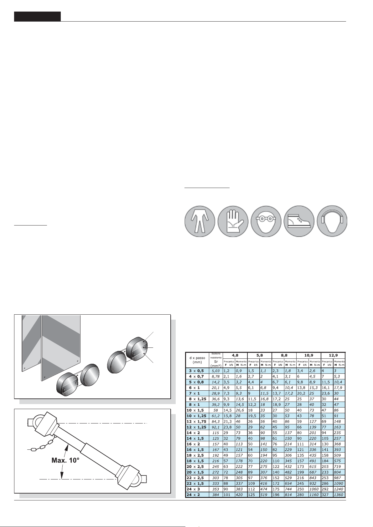
DEUTSCH
GEBRAUCH UND WARTUNG
32) In Kurven ist Vorsicht geboten, da durch die geänderte Lage
des Schwerpunkts mit oder ohne Ausrüstung eine Fliehkraft
entsteht. Gleichermaßen ist Vorsicht auf abschüssigen
Straßen und an Gefällen geboten.
33) Beim Transport müssen die Ketten der seitlichen
Schlepperhebearme eingestellt und befestigt werden; prüfen,
daß die Abdeckungen der Saatgut- und Düngerbehälter gut
verschlossen sind. Den Schalthebel der hydraulischen
Hubvorrichtung in die blockierte Stellung bringen; die
Säelements einhängen die Anleitungen genau zu befolgen
(pag.68).
34) Vor dem Befahren von Straßen sind die Behälter zu entleeren.
35) Fortbewegungen ausserhalb des Arbeitsbereichs dürfen nur
erfolgen, wenn das Gerät sich in der Transportposition
befindet.
36) Der Hersteller liefert auf Anfrage Ausrüstungen und Tabellen
zur Kennzeichnung des Raumbedarfs.
37) Wenn die geschleppten oder an dem Schlepper
angebrachten Ausrüstungen und Geräte die Sichtbarkeit der
Signalisierungs- und Beleuchtungsvorrichtungen des
Schleppers verdecken, müssen diese Vorrichtungen auch
an den Ausrüstungen angebracht werden, wobei die
Vorschriften der im jeweiligen Anwendungsland geltenden
Straßenverkehr-sordnung zu beachten sind. Beim Gebrauch
ist zu kontrollieren, daß die Anlange einwandfrei funktioniert.
Nachstehend wird die korrekte Sequenz der Leuchten
angegeben (Abb. 5):
A- Richtungsanzeiger
B- Rote Positionsleuchte
C- Bremslicht
Transport- als in Arbeitsposition.
44) Den Kardanwellenschutz oft und regelmäßig prüfen; dieser
muß immer in einwandfreiem Zustand sein.
45) Vor dem Einschalten der Zapfwelle muß die Solldrehzahl
erreicht sein. Sicherstellen, daß die Drehzahl mit der Drehzahl
übereinstimmt, die auf dem an der Maschine angebrachten
Aufkleber angegeben ist.
46) Vor dem Einschalten der Zapfwelle ist sicherzustellen, daß
sich weder Personen noch Tiere im Wirkungskreis aufhalten
und daß die eingestellte Drehzahl der Solldrehzahl entspricht.
Nie die vorgesehene Höchstdrehzahl überschreiten.
47) Auf die sich drehende Gelenkwelle achten.
48) Die Zapfwelle nicht bei abgestelltem Motor oder gleichzeitig
mit den Rädern einschalten.
49) Die Zapfwelle immer ausschalten, wenn die Kardanwelle
einen zu großen Winkel einnimmt (nie über 10 Grad – Abb.
6) und wenn sie nicht gebraucht wird.
50) Die Kardanwelle nur reinigen und fetten, wenn die Zapfwelle
ausgeschaltet ist, der Motor stillsteht, die Feststellbremse
gezogen und der Zündschlüssel herausgezogen ist.
51) Die Kardanwelle in ihre spezielle Halterung legen, wenn sie
nicht verwendet wird.
52) Nach dem Ausbau der Kardanwelle den Zapfwellenanschluß
wieder mit dem Stutzen verschliessen.
Sichere Wartung
Bei der Arbeit und der Wartung sind geeignete individuelle
Schutzmittel anzuwenden:
Gelenkwelle
38) Die angeschlossene Ausrüstung kann nur gesteuert werden,
wenn ihre Kardanwelle mit Überbelastungssicherheits- und
Schutzvorrichtungen versehen ist und wenn diese mit der
speziellen Kette befestigt sind.
39) Ausschließlich die vom Hersteller vorgesehene Kardanwelle
benutzen.
40) Ein- und Ausbau der Kardanwelle muß immer bei
abgestelltem Motor erfolgen.
41) Stets auf die richtige Montage und die Sicherheit der
Kardanwelle achten.
42) Die Drehung des Kardanwellenschutzes mittels der
mitgelieferten Kette verhindern.
43) Stets auf den Kardanwellenschutz achten, sowohl in
A
B
C
fig. 5
53) Wartungs- und Reinigungsarbeiten nicht vor dem
Ausschalten des Motors, dem Anziehen der Feststellbremse
und der Blockierung des Schleppers mit einem Keil oder
einem geeignet großen Stein unter den Rädern durchführen.
54) Regelmäßig prüfen, daß alle Schrauben und Muttern korrekt
festgezogen sind und sie eventuell festziehen. Für diese
Eingriffe ist ein Momentenschlüssel zu verwenden, wobei
für Schrauben M10 Widerstandsklasse 8.8 ein Wert von 53
Nm, für Schrauben M14 Widerstandsklasse 8.8 ein Wert von
150 einzuhalten ist (Tabelle 1).
55) Bei Montage-, Wartungs-, Reinigungs-,
Zusammenbauarbeiten, usw., sind als Vorsichtsmaßnahme
geeignete Stützen unter dem Gerät anzubringen.
56) Die Ersatzteile müssen den vom Hersteller festgelegten
Ansprüchen entsprechen. Nur Originalersatzteile
verwenden.
Ta be l le 1
fig. 6
70
-
cod. 19501381
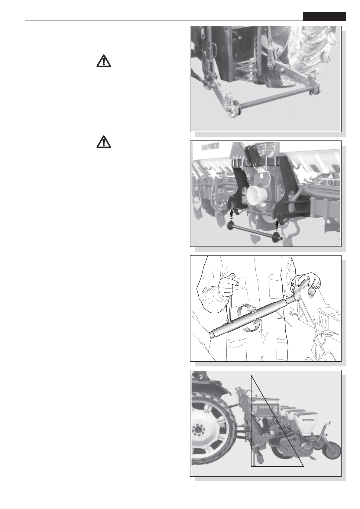
GEBRAUCH UND WARTUNG
3.0 BETRIEBS-ANLEITUNGEN
Um die besten Leistungen des Geräts zu erhalten, immer die
folgenden Anleitungen beachten.
ACHTUNG
Alle Wartungs, Einstellungs und Rüstarbeiten müssen ausschliesslich nur mit ausgeschalteter Schlepperzapf-welle,
Sämaschine mit auf dem Boden stehenden Stützfüssen,
abgestelltem und gut gesichertem Schlepper und
herausgezogenem Zündschlüssel durchgeführt werden.
DEUTSCH
3.1 EINBAU AM SCHLEPPER
Die Sämaschine kann an jeden Schlepper mit universeller
Dreipunkt-Kupplung angekuppelt werden.
GEFAHR
Der Anbau am Schlepper ist sehr gefährlich. Bei der
Durchführung dieses Eingriffs sind die Anleitungen genau zu
befolgen und es ist sicherzustellen, dass sich keine Personen
der Maschine nähern.
Die richtige Position von Schlepper und Sämaschine wird erreicht,
indem das Gerät in einem Abstand vom Schlepper aufgestellt
wird, daß die Gelenkwelle um 5-10 cm im Vergleich zur engsten
Anschlussposition hervorragt. Nun wie folgt vorgehen:
1) Die Sämaschinenstange (1 Abb. 7) an das Hubwerk
anschließen und mit den Einrast-Splinten absichern.
2) Sich mit derselben unter die Senkrechte der
Sämaschinenankupplungspunkte begeben (Abb. 8). Das
Hubwerk anheben, bis die Stangensperrvorrichtung einrastet.
3) Die Ketten der Kraftheberstangen einhängen. Die Stangen
parallel zum Schlepper mittels der dazu bestimmten
Zugstangen blockieren. Diese Sicherheit muss angebracht
werden, um jegliche waagrechte Bewegung der Sämaschine
zu vermeiden.
4) Den oberen dritten Punkt (2 Abb. 9) ankuppeln; der Stift muß
durch seinen Splint blockiert werden; mit der
Einstellzugstange (3 Abb. 9) die Säelemente parallel zum
Boden ausrichten (Abb. 10).
5) Die Gelenkwelle einkuppeln und sicherstellen, daß sie fest
mit der Zapfwelle verbunden ist. Sicherstellen, daß sich der
Schutz frei dreht und ihn mit der vorgesehenen Kette
befestigen.
fig. 7
1
fig. 8
2
3
cod. 19501381
fig. 9
fig. 10
-
71
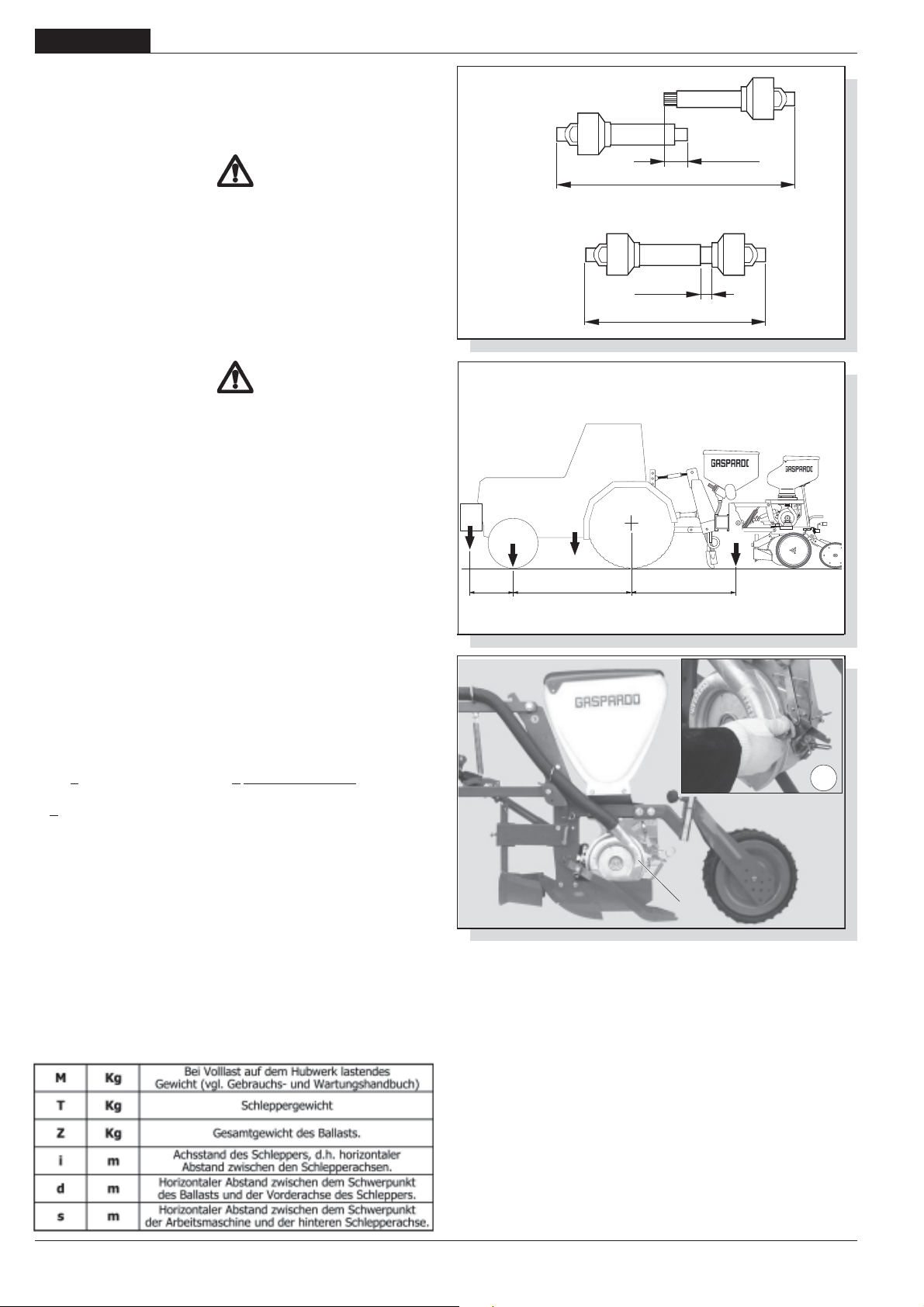
DEUTSCH
GEBRAUCH UND WARTUNG
3.2 ANPASSUNG DER GELENKWELLE
Die mit der Maschine gelieferte Gelenkwelle hat Standardlänge,
aus diesem Grunde kann ihre Anpassung notwendig sein. In
diesem Fall sich vor dem Eingriff an den Hersteller der
Gelenkwelle für deren eventuelle Anpassung wenden.
VORSICHT
- Wenn die Gelenkwelle soweit als möglich herausgezogen
ist, müssen sich die beiden Rohre mindestens 15 cm
überlappen (A Abb. 11). Wenn sie soweit als möglich
eingezogen ist, muss ein Minimalspiel von 4 cm. (B Abb. 11)
bestehen.
- Bei Gebrauch des Geräts an einem anderen Schlepper das
obengenannte prüfen, ausserdem prüfen, daß die sich
drehenden Teile der Gelenkwelle vollkommen durch ihre
Schutzvorrichtungen abgedeckt sind.
ACHTUNG
Bei Transport der Sämaschine immer die Anweisungen des
Herstellers befolgen.
3.3 STABILITÄT VON SÄMASCHINE-SCHLEPPER BEIM
TRANSPORT
Wenn eine Sämaschine an den Schlepper angekuppelt wird,
und somit gemäß Straßenverkehrsordnung zu einem Teil des
Schleppers wird, kann die Stabilität der Einheit SchlepperSämaschine schwanken und zu Schwierigkeiten beim Fahren
oder bei der Arbeit führen (Aufbäumen oder Schleudern des
Schleppers). Das Gleichgewicht kann wiederhergestellt werden,
indem das Vorderteil des Schleppers mit Ballast versehen wird,
um das auf die beiden Achsen des Schleppers einwirkende
Gewicht ausreichend gleichmäßig zu verteilen.
Für die Arbeit unter sicheren Bedingungen sind die Vorschriften
der Straßenverkehrsordnung zu beachten, die vorschreiben,
dass mindestens 20% des alleinigen Schleppergewichtes auf
der Vorderachse lasten muss und dass das auf den Armen des
Hubwerks lastende Gewicht nicht über 30% des
Schleppergewichts liegen darf. Diese Betrachtungen sind in
den nachstehenden Formeln zusammengefasst:
A
B
cm 4 min
fig. 11
ZT
0,2 T
d
fig. 12
i
cm 15 min
Max
Min
M
s
< 0.2 x T x i + Z x (d+i) Z > (M x s)-(0.2 x T x i)
M x s
(d+i)
M < 0.3 x T
Das Ballastgewicht, das gemäß der Formel erforderlich ist, ist
als Mindestballast für die Teilnahme am Straßenverkehr
anzusehen. Wenn es aus Leistungsgründen des Schleppers
oder zwecks besserer Trimmlage der Sämaschine bei der Arbeit
erforderlich sein sollte, das Ballastgewicht zu erhöhen, ist das
Schlepperhandbuch bezüglich des maximalen Ballastgewichtes
zu konsultieren. Falls die Formel zur Berechnung des Ballastes
zu einem negativen Ergebnis führt, ist kein zusätzliches Gewicht
anzubringen. Auf jeden Fall ist es unter Beachtung der Grenzwerte
des Schleppers möglich, eine geeignete Anzahl von Gewichten
anzubringen, um eine bessere Stabilität beim Fahren zu
gewährleisten. Die Symbole haben folgende Bedeutung:
(zur Bezugnahme siehe Abb. 12)
A
fig. 13
3.4 SÄAPPARAT
In die Säapparate (1 Abb. 13) wird eine Scheibe montiert (1 Abb.
14), die je nach Samengrösse (der Samen darf nicht in das Loch
gehen) gewählt wird. Die Samen, die durch Ansaugung die
Scheibenlöcher verstopfen, werden dann auf dem Acker verteilt.
Die Sämaschine wird dem Kunden mit einem Scheibenset
geliefert. Folgende Scheibenserien können vom Hersteller an
den Kunden geliefert werden (Siehe auf Seite 75).
1
72
-
cod. 19501381
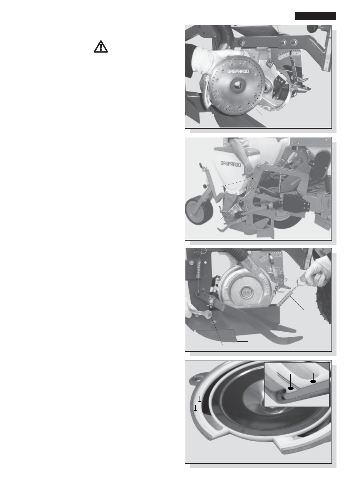
GEBRAUCH UND WARTUNG
3.5 WECHSELN DER AUSSAATSCHEIBEN UND
EINSTELLUNGEN
VORSICHT
Alle hier beschriebenen Tätigkeiten sind in sauberer, nicht
staubiger Umgebung durch erfahrenes, mit
Schutzhandschuhen ausgestattetes Fachpersonal
durchzuführen.
Die Sämaschine muss sauber und trocken, vom Schlepper
abgekuppelt und fest aufgestellt sein.
- Es dürfen nur saubere Teile montiert werden, die sich in
gutem Zustand befinden.
- Die Sprossen müssen beim Einbau der Scheibe gegen den
Säapparat gerichtet sein (1 Abb. 14).
- Falls an der Scheibe Sprossen fehlen oder sie sind
gebogen, sind Fremdkörper in den Säapparat
eingedrungen; in diesem Fall muss die Scheibe gewechselt
werden.
- Eventuelle kreisförmige Schlier-enbildungen dürfen nicht
mehr als 1/3 der Scheibenstärke sein.
- Die Flügelmutter zum Deckelverschluss nur mit den
Händen anziehen (A Abb. 13).
DEUTSCH
1
fig. 14
Achtung: Beim Auswechseln verschlissener Scheiben ist es
empfehlenswert, auch die Deckeldichtung zu ersetzen.
Folgende Arbeiten müssen durchgeführt werden:
1) Nur ein Säelement auf folgende Weise vom Boden heben:
- Die Feder (1 Abb. 15) einhängen;
- Das Säelementt heben, bis es einhakt;
- Die Feder (2 Abb. 15) wieder einhängen;
2) Falls montiert, die rück-schlagverhindernden Schrauben (4
Abb. 16) entfernen;
3) Den Säscharenreisser (2 Abb. 16) durch Entfernung der
Feder aushaken (3);
4) Die Flügelmutter aufschrauben und entfernen (A Abb. 13);
5) Den Deckel des Säapparats öffnen;
6) Die Scheibe einsetzen oder ersetzen;
7) Gegebenenfalls das Saatgutüberlaufschutzplättchen wie
später beschrieben einstellen;
8) Den Deckel schließen, die Unterlegscheibe einsetzen und
mit der Flügelmutter festschrauben; den Spurreisser
ankuppeln und die Rückprallschutzschraube montieren (falls
vorhanden);
9) Den Wähler, wie weiter vorne angegeben, einstellen;
10) Das Säelement in entgegen-gesetzter Richtung zur
Beschreibung in Punkt 1 senken.
3.5.1 ERSETZEN DER DECKELDICHTUNG
Die gesamte Oberfläche der Saatgutstreuerdeckeldichtung (A
Abb. 17) regelmäßig auf Verschleiss kontrollieren.
Die Dichtung ist zu ersetzen bevor die Oberfläche «A» (Abb. 17)
infolge des durch den Scheibenbetrieb bedingten Verschleisses
die Oberfläche «B» erreicht. Es ist ferner zu überprüfen, dass die
Scheibe keinen Rillen an der Oberfläche «A» erzeugt hat.
fig. 15
fig. 16
1
2
3
2
1
B
A
cod. 19501381
A
B
fig. 17
-
73

DEUTSCH
GEBRAUCH UND WARTUNG
3.6 SÄMENAUSWERFER
Sämenauswerfer nur bei Rübensaat verwenden.
Samenauswerfer bei großem Samenkaliber, z.B. Mais,
Sonnenblume, Soja, Erdnüssen usw. ausbauen. Die Schrauben
lösen (1 Abb. 18) und den Samenauswerfer entfernen (2).
Montage
Den Samenauswerfer (2) nach Bild (18) aufstellen.
Gengen den Rand des dazu bestimmten Sitzets drücken (3 Bild
18) und mit der mitgelieferten Schraube (1) befestingen.
Schraube nur in der vorgegebenen Richtung montieren. Kein
Distanzstück dazwischenlegen.
Überprüfen, daß der Samenauswerfer an der Lochscheibe haftet.
Den Samenauswerfer bei anschaulichem Verschleiß ersetzen.
2
1
3
3.7 EINSTELLUNG DES WÄHLERS
Durch Bewegung des Anzeigers (1 Abb. 19 und 20) wird ein
Läufer gesteuert (2 Abb. 19 und 20), der die Scheibe in der Nähe
der Löcher berührt und den Fall der überflüssigen Samen
verursacht. Der Wähler muss bei jedem Samen- und
Scheibenwechsel eingestellt werden, für kleine Samen in
Richtung der niedrigen Zahlen (Abb. 19), für grosse Samen in
Richtung der höheren Zahlen (Abb. 20). WICHTIG: Der Wähler
reguliert nicht den Luftdurchsatz im Verteiler.
3.8 EINSTELLUNG DER ÜBERLAUFPLATT
Die Überlaufplatte (1 Abb. 21) kann in drei Stellungen eingestellt
werden und bestimmt die Öffnungsweite des Sameneinlaufs (2
Abb. 21), so daß die Samen nicht infolge einer übermässi-gen
Zufuhr aus dem Verteiler aus-treten können. Diese Einstellung
ist vor allem bei besonders steilem Boden und bei kleinen Samen
erfor-derlich. Im letzteren Fall könnte es erforderlich sein, die
Standard-scheibe durch eine spezielle Scheibe aus-zuwechseln,
die nur für kleine Samen verwendet wird.
Bestellnummer dieser Scheibe: 22270133.
fig. 18
1
2
fig. 19
1
2
fig. 20
1
2
fig. 21
74
-
cod. 19501381

GEBRAUCH UND WARTUNG
3.9 DISTANZA LONGITUDINALE DI SEMINA
Der Längs-Säabstand wird durch die Anzahl der Öffnungen der
Lochscheibe, die Anzahl der Zähne und der Stellung der
Zahnräder auf dem die Bewegung auf das Getriebe
übertragenden Rad und der Zahnräderkombination im
Getriebekasten bestimmt. Auf dem Deckel des
Getriebegehäuses befindet eine Tabelle zur Einstellung des
Aussaatabstands und eine Tabelle mit Angabe des auf das Rad
montierten Antriebs, das das Getriebe in Bewegung setzt.
Für die Einstellung des Aussaatlängsabstandes wie folgend
beschrieben vorgehen, sich dabei auf die Tabelle auf Seite 76
beziehen:
- Die in das Säaggregat einzubauende Scheibe je nach Ausmass
der zu pflanzenden Samen wählen;
- Am Säaggregat prüfen, wieviele Zähne die in Tabelle auf Seite
76 angegebenen Ritzel (Rad) haben;
- Die Tabelle suchen, in der das Ritzelpaar angegeben ist, das
im Säaggregat montiert ist;
- In der Spalte der gewählten Scheibe den gewünschten
Aussaatabstand suchen;
- Sich nach links bewegen und ablesen, auf welches Räderpaar
(A - B) die Getriebekette gelegt wird;
- Um die Kette zu verschieben, den Deckel des Getriebekastens
öffnen und die Kette (1 Abb. 22) durch den Hebel (2) lockern;
- Die Kette auf die Zahnräder legen und diese ausrichten (Abb.
23).
- Die Kette erneut mit dem Hebel (2 Abb. 22) spannen und den
Deckel schließen.
- Wenn mit den an der Sämaschine angebrachten Ritzeln (Rad)
nicht der gewünschte Säabstand erhalten wird, ist in der Tabelle nachzusehen, ob die Stellung der Ritzel zu ändern ist
oder ob diese zu ersetzen sind.
fig. 22
fig. 23
DEUTSCH
2
1
3.10 SÄSCHEIBEN
(*) Speziell für Bohnen.
(**) Es wird empfohlen den Deckel des Säapparats durch einen
spe-ziellen Deckel für kleine Samen auszuwechseln.
Für andere Samenarten fragen Sie bitte bei uns nach. Die in
der Tabelle angegebenen Werte dienen nur als Anhaltspunkt.
Die Auswahl der richtigen Sä-scheibe obliegt dem Anwender.
Das Unternehmen Gaspardo übernimmt keine Haftung für
Aussaaten, die mit den falschen Säscheiben durchgeführt
wurden.
cod. 19501381
-
75

DEUTSCH
3.11 TABELLE
AUSSAATLÄNGSABSTAND
GEBRAUCH UND WARTUNG
76
-
cod. 19501381

3.12 SAATGUTBEDARFTABELLE
GEBRAUCH UND WARTUNG
DEUTSCH
cod. 19501381
-
77

DEUTSCH
GEBRAUCH UND WARTUNG
3.13 REGELUNGEN
3.13.1 EINSTELLUNG DER SÄSCHAREN-REISSERTIEFE
Damit die Pflänzchen richtig aus dem Erdreich wachsen, ist es
wichtig, die Samen in der richtigen Aussaatbettiefe einzulegen.
Durch Betätigung des Griffs wird die Höhenposition der Säschar
geändert, wodurch die Scharentiefe, in die der Samen gelegt
werden muss, bestimmt wird (1 Abb. 24). Der Stufenanzeiger
dient zur gleichen Tiefeneinstellung aller Säscharenreisser.
Der Zeiger der Einstellskala ist rein progressiv und zeigt auf
keinen Fall eine Höhenänderung die Saattife in cm an.
3.13.2 EINSTELLUNG DES SCHUBDRUCKS DES
SÄSCHARENREISSERS
Die das Erdreich aufschneidende Aktion der Säschar wird durch
die von der Feder gegebene Ladung bewirkt. Unterschiedliche
Arbeitsbedingungen führen dazu, den Druck auf den Boden
einstellen zu müssen; durch Veränderung der Federposition nach
vorne oder nach hinten wird stärkeres oder geringeres
Durchdringungs-vermögen eingeprägt (1 Abb. 26). Die Position
der Feder an ihrer Basis, der dreilöchrigen Platte verändern,
wenn keine zufriedenstellenden Einstellungen erreicht werden.
In der Rüben-Konfiguration kann das Säaggregat mit einem
Saatgutdrückrad ausgerüstet werden. Die Feder (1, Abb. 27)
drehen, um den Druck des Rades auf den Boden zu ändern. Bei
feuchten Böden ist das Saatgutdrückrad nicht anzuwenden:
dazu wird das Rad angehoben und mit dem Splint gesperrt (2,
Abb. 27).
1
fig. 24
1
fig. 26
fig. 25
1
fig. 27
78
1
-
2
cod. 19501381

GEBRAUCH UND WARTUNG
3.13.3 AUSSCHLUSS DES SÄELEMENTS
Den Schlepper abstellen und den Motorzündschlüssel ziehen;
Das einzelne Säelement wie folgt vom Boden heben:
- Die Feder (1 Abb. 15) einhängen;
- Das Säelementt heben, bis es einhakt;
- Die Feder (2 Abb. 15) wieder einhängen;
Dann die Antriebswelle des Säelements (Abb. 28) wie folgt
aussetzen:
- Die Muffe (1 Abb. 28) in die durch den Pfeil angegebene Richtung
drücken und gedrückt halten, die Nutmutter (2 Abb. 28) nach
vorne drücken und gleichzeitig drehen, bis die von dem Eisenstift
befreit wird;
– Die Muffe (1 Abb. 28) wieder bis zum Anschlag zurückziehen.
– Um den Antrieb wiederherzustellen, die Muffe nach vorne
schieben und den Stulp wieder mit dem Eisenstift blockieren.
3.13.4 GETRIEBEKASTEN SÄMASCHINE
Jeder Kasten ist mit einem Sicherheitsstift (3, Abb. 29)
ausgerüstet, wenn die Drehung der Lochscheibe infolge des
Eindringens von Fremdkörpern (Papier, Seile, usw.) blockiert wird.
In diesem Fall das Saatgut aus den Behältern abzulassen, das
Säaggregat überprüfen und reinigen, die Sprossen der Scheibe
überprüfen und den Sicherheitsstift ersetzen.
WICHTIG! Keine Metallstifte verwenden.
ACHTUNG! Die Feststellschrauben des Kastens (4, Abb. 29) nicht
bis zum Anschlag anziehen, eine gewisse Schwingung ist
erforderlich.
DEUTSCH
2
1
fig. 28
fig. 29
3
4
5
Corretto-
Correct
-Korrector
cod. 19501381
-
79

DEUTSCH
GEBRAUCH UND WARTUNG
3.14 SPURREISSER
Der Spurreisser ist eine Vorrichtung, die eine parallel zum
Schlepper verlaufende Bezugslinie im Boden markiert.
Wenn der Schlepper seinen Lauf beendet hat und die Strecke
zurückläuft, wird er mit einem der Vorderräder auf der Bezugslinie
fahren (Abb. 30). Bei jedem neuen Durchlauf muss die
Sämaschine eine auf der Gegenseite des vorhergehenden
Durchlaufs liegende Bezugslinie markieren. Die Umkerhrung
der Ausleger zur Spurmarkierung wird durch die Steuerung des
Hydraulikverteilers des Schleppers ausgelöst. Auf Anfrage kann
der Hersteller einen Kit zum Umbau des Spurreissers von
hydraulisch auf mechanisch liefern.
3.14.1 HYDRAULISCHER SPURREISSER
Die Sämaschine ist mit einer öldynamischen SpurreisserSteuervorrichtung ausgerüstet. Die Tauchzylinder müssen mittels
der entsprechenden öldynamischen Schläuche an die
Hilfsverteiler des Schleppers angeschlossen werden.
In dem Anschluss des öldynamischen Zylinders ist ein geeichter
Stift enthalten, der durch eventuell in Öl enthaltene
Verunreinigungen verstopft werden kann.
Falls der Betrieb unregelmäßig sein sollte, ist der Nippel
auszubauen und die Öffnung des geeichten Stiftes zu reinigen.
Dann werden diese Teile wieder eingebaut, wobei zu beachten
ist, dass der Stift in der korrekten Richtung in den Anschluss
eingesetzt wird. Auf Wunsch kann der öldynamische Spurreisser
ist mit einem Ventil ausgerüstet werden, das die zwei Arme
abwechselnd antreibt. In diesem Fall ist nur ein einziger
öldynamischer Verteiler des Schleppers erforderlich.
fig. 30
Sicherheitsmaßnahmen bezüglich des Hydrauliksystems:
1) Beim Anschluß der Rohrleitungen an die Hydraulikanlage
des Schleppers ist darauf zu achten, daß weder die
Hydraulik der Maschine, noch jene des Schleppers unter
Druck steht.
2) Bei funktionellen hydraulischen Verbindungen zwischen der
Maschine und dem Schlepper sollten die einzelnen
Anschlüsse mit unterschiedlichen Farben gekennzeichnet
werden, um einen fehlerhaften Betrieb zu vermeiden.
Falsche Anschlüsse können Unfälle verursachen.
3) Die Hydraulikanlage steht unter hohem Druck. Aufgrund
der Unfallgefahr ist für die Kontrolle auf eventuelle undichte
Stellen ausschließlich diesbezüglich geeignetes Werkzeug
zu verwenden.
Einregulierung der Anlagen
Die mitgelieferten öldynamischen Anlagen sind mit Flußreglern
(Abb. 32) ausgestattet, die eine Einstellung der Ölmenge beim
Öffnen oder Schließen je nach Montagerichtung derselben
ermöglichen:
Fluß von A nach B frei;
Fluß von B nach A gedrosselt (eingestellt).
Die Feststellnutmutter (2) lockern und den Drehknopf (3) zwecks
Einstellung drehen. Nach der Einstellung ist die
Feststellnutmutter wieder festzuziehen.
fig. 31
(A)
1
(B)
2
fig. 32
ACHTUNG
Die Einstellung muß derart erfolgen, daß die Auf- und
Abstiegsgeschwindigkeit nicht zu einer Beschädigung der
Struktur führt. Der vorgeschriebene Druck der öldynamischen
Anlage darf nie überschritten werden.
80
-
3.14.2 AUTOMATIKSTEUERUNG DES MECHANISCHEN
SPURREISSERS
Auf Anfrage kann der Hersteller einen Kit zum Umbau des
Spurreissers von hydraulisch auf mechanisch liefern. Die Anfrage
muss mit der Beschreibung des Typs und Modells der
Sämaschine ausgestattet sein. Für den Umbau werden alle
bereits in der Maschine vorhandenen Teile wiederverwendet.
Der Spurreisser wird rechts oder links des Schleppers durch
eine Automatiksteuerung aktiviert (Abb. 33), die von der Bewegung
des Schlepperkrafthebers betrieben wird. Dafür genügt es, den
Schlepperkraftheber einmal zu heben und einmal zu senken.
cod. 19501381

GEBRAUCH UND WARTUNG
Einregulierung
Falls der Bolzen (1 Abb. 33) nicht in die Scheibe (2) einhakt oder
umgekehrt nicht von ihr aushakt, die Arme (3) in der Höhe
einstellen. In Arbeitsposition müssen die Seile gut gespannt sein.
3.14.3 EINSTELLUNG DER SPURMARKIERERSCHEIBEN
An den beiden Auslegern des Spurmarkierers die
Scheibenhalterungsmuffe (1 Abb. 34) befestigen, ohne die
Muttern vollständig festzuziehen; die Scheibe einsetzen und mit
dem Einraststift befestigen. Aus der nebenstehenden Tabelle 2
den Abstand (L Abb. 30) entnehmen, in dem die Scheibe die
Bezugslinie ziehen soll. Die Scheibe auf den korrekten Abstand
einstellen, sie leicht schrägstellen und die Muttern vollständig
festziehen (Abb. 35). Die korrekte Position der Scheibe auf
normalen Böden ist auf der Abb. 36 Ref. A dargestellt; auf
schweren Böden ist die Scheibe umzudrehen (siehe Abb. 36,
Ref. B). Für nicht in der Tabelle vorgesehene Abstände ist Bezug
auf die nachstehende Regel zu nehmen:
L=
D (N +1) - C
2
L= Abstand zwischen dem letzten Aussenelement und dem
Spurmarkierer.
D= Abstand zwischen den Reihen.
N= Anzahl der in Betrieb stehenden Elemente.
C= Vordere Spurbreite des Schleppers.
Beispiel:
D=75cm; N=8 Elemente; C=190cm.
DEUTSCH
1
2
3
fig. 33
1
nr 17
75 (8+1) – 190 = 242,5 cm
L =
2
Beim Fahren auf öffentlichen Straßen sind die
Reihenmarkierscheiben in das Innere des Maschinenkörpers
zu drehen (Abb. 37).
ACHTUNG
Ta b el l a 2
fig. 34
Avanzamento
Advancement
Avancement
fig. 36
fig. 37
fig. 35
A
B
cod. 19501381
-
81

DEUTSCH
GEBRAUCH UND WARTUNG
3.13 VERTEILUNG DER CHEMISCHEN PRODUKTE
Die Verteilung von Düngemitteln und Schädlingsbekämpfungsmitteln erfolgt mittels der dafür bestimmten Dosierer (1 Abb.
38), die unter den entsprechenden Behältern angebracht sind.
Die Dosierer werden durch das Drehen der Ringmutter (2 Abb.
38) eingestellt. Anhand der Dosierereinstellung kann man den
nachstehenden Tabellen die für die Behandlung eines Hektars
erforderliche Düngeroder Schädlings-bekämpfungsmittelmenge
entnehmen.
BEFÜLLEN DER BEHÄLTER UND TRICHTER
Die Behälter und Trichter können manuell oder mittels eines
Hubwerks befüllt werden, dessen Hubkapazität über 200 kg
liegen muss und das von den zuständigen Ämtern zugelassen
sein muss. Es wird darauf hingewiesen, dass zum Heben von
Gewichten über 30 kg mehrere Personen benötigt werden oder
dass das oben beschriebene mechanische Hubwerk verwendet
werden muss, wobei die in dem Betriebs- und
Wartungshandbuch desselben enthaltenen Anleitungen zu
befolgen sind.
VORSICHT
- Das Befüllen und Entleeren der Düngerstreuer muss bei auf
den Boden abgesenkter stillstehender Sämaschine,
geöffnetem Rahmen, gezogener Standbremse,
angehaltenem Motor und gezogenem Zündschlüssel
erfolgen. Sicherstellen, dass sich weder Personen noch
Tiere den chemischen Stoffen nähern können.
- Alle Eingriffe müssen von Fachpersonal, dass über geeignete
Schutzausrüstungen (Arbeitsanzug, Handschuhe, Stiefel,
Masken, usw.) verfügt, in einer sauberen nicht staubhaltigen
Umgebung durchgeführt werden.
- Auf keinen Fall Düngermittelsäcke oder andere Gegenstände
auf die Abdeckungen der Düngerstreuerkästen legen, um
eine Beschädigung derselben sowie Personen- und
Sachschäden zu verhindern.
- Das Beladen erfolgt an den Außenseiten.
- Beim Einfüllen der Samen, Düngemittel und
Schädlingsbekämp fungsmittel in die entsprechenden
Behälter ist darauf zu achten, daß keine anderen Körper
eintreten (Schnüre, Sackpapier, usw.).
- Die Sämaschine kann chemische Stoffe befördern.
Personen, Kindern und ist der Zutritt zur Sämaschine zu
untersagen.
fig. 38
fig. 39
2
19
NR -.........
1
1
1
1
FASSUNGSVERMÖGEN DER BEHÄLTER
Serbatoio
(mm)
500
850
A
1100
1500
250
B
250
A - Spandiconcime; B - Microcranulatore; (*) - Solo con serbatoi in metallo.
Materiale
Metallo Plastica
Capacit
Rialzo
(Litri)
(Litri)
92,5
157
203 97(*) 980(*)
277
15
16
Top
(Litri)
Die Streuer aus Kunststoff benötigen keine Schmierung. Am
Arbeitsende wird eine sorg-fältige Reinigung des Behälters, vor
allem der Dünger-behälter empfohlen. Die Deckel der
Ablasstutzen abschrauben, eventuelle Produktreste sammeln
(Abb. 39) und die Behälter gründlich mit Wasser waschen. Bei
der Entsorgung von umweltverschmutzenden Flüssigkeiten die
Umweltschutzbestimmungen.
3.15.1 EINSTELLUNG DER DÜNGEREINGRABVORRICHTUN GEN
Die Flügel zum Eingraben des Düngers wirken in einem
Standardabstand parallel zur Aussaatreihe ein. Vor dem
Gebrauch der Sämaschine ist zu kontrollieren, daß dieser
Abstand für die Anzahl der zu behandelnden Hektar und das
verwendete Düngemittel geeignet ist, damit die Pflanzen nicht
beschädigt werden. Den Abstand zur Aussaatreihe eventuell
vergrößern. Auch die Eingrabtiefe des Dünge-mittels ist
einzustellen, wozu die Höhe der Feder eingestellt wird (Abb. 40).
fig. 40
fig. 41
82
-
cod. 19501381
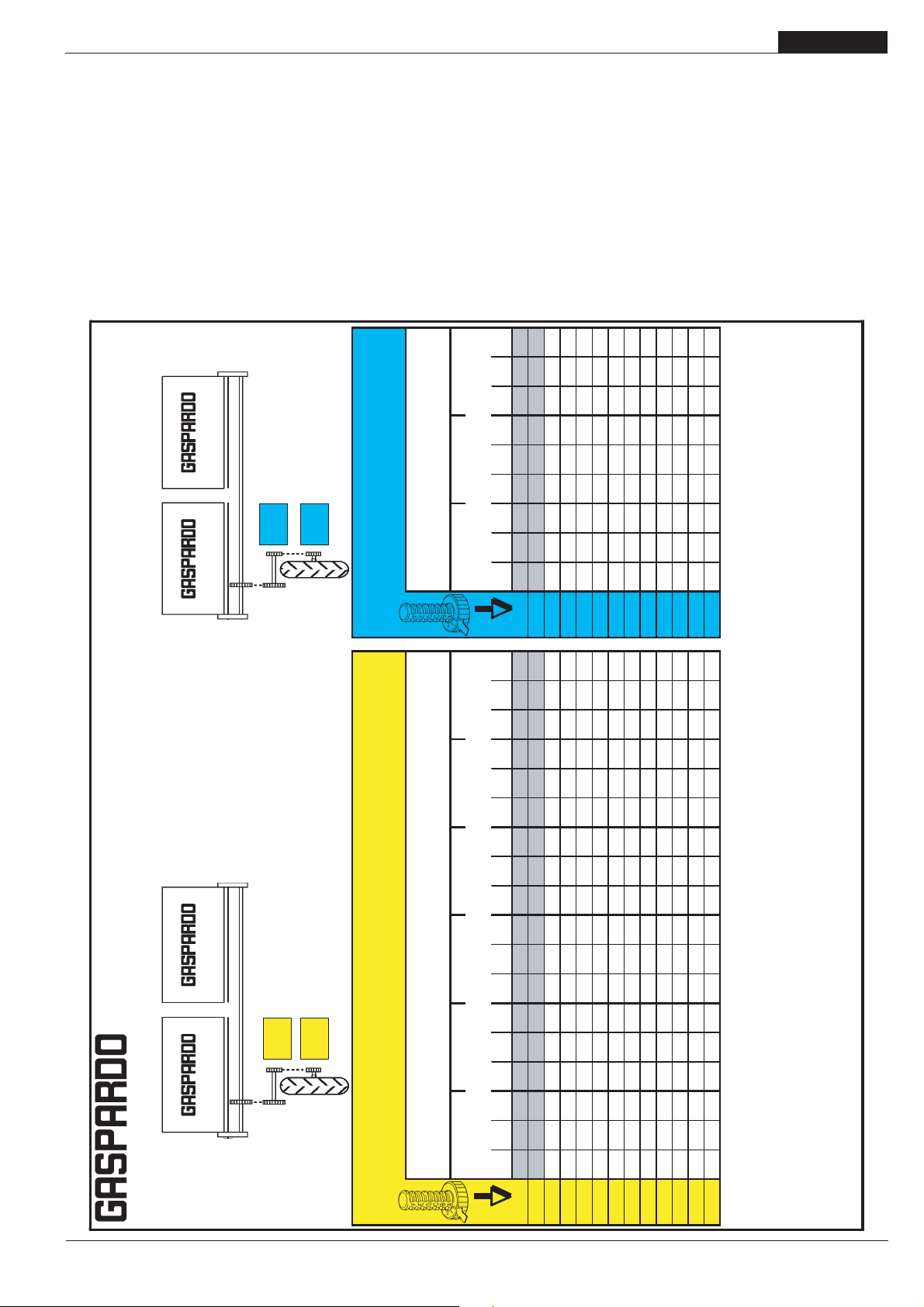
GEBRAUCH UND WARTUNG
DEUTSCH
Nach der Durchführung dieses Eingriffs sollte das
überschüssige Schlauchstück abgeschnitten werden, um zu
vermeiden, daß der Schlauch sich verbiegt, was den Durchfluss
des Düngemittels behin-dern könnte (Abb. 40).
3.15.2 SPEEDY SET
Der Düngerstreuerbehälter kann mit dem SPEEDY SET (Fig. 41)
ausgerüstet werden, der das Einstellen der volumetrischen
Dosierungsvorrichtungen MINIMAX (angemessen umgebaut) mit
einem einzigen Eingriff auf jedem einzelnen Behälter ermöglicht.
Regelmäßig kontrollieren, dass die Schiebeklappen korrekt
ausgerichtet sind. Nachstehend wird die für diese Einstellung
geeignete Streuungstabelle (19702951) aufgeführt.
Posici n
- Reihenabstand
- Distancia entre las hileras
bersetzung d entrainemet
Trasmissione ruota motrice
Transmission drive wheel
Z25
Transmision roue motrice
Z15
- Prospectos de distribuci n
Position of distributor adjustment
Transmici n de la rueda motriz
Position reglage distributeur -
Row spacing
Interfila -
Distance entre les lignes
Abonadora
Z20
- D ngermengetabelle
Z20
R15 (*)
Einstellung Einstellvorrchtung -
5.00/80
regulaci n distribuidor
Posizione regolazione distributore -
3.15.3 DÜNGERSTREUER - Tabelle Kg/Ha
ACHTUNG: Die auf die ersten Positionen (B0÷C0 o 1÷1,5 bei
SPEEDY SET) eingestellte Dosierungsvorrichtung MINIMAX kann
aufgrund der reduzierten Öffnung verstopfen, besonders wenn
Düngemittel mit unregelmäßiger Körnergröße verwendet werden.
Wenn die auszustreuende Düngermenge unter die ersten
Positionen (dunkle Zeilen auf der Tabelle) fällt, ist der Hersteller
zu kontaktieren. Die in der Tabelle angegebenen Werte sind reine
Anhaltswerte, da das spezifische Gewicht und die Körnergröße
oft von diesen Werten abweichen. Auf jeden Fall ist immer Bezug
auf das auf der Produktpackung angegebene spezifische Gewicht
zu nehmen. Falls das spezifische Gewicht nicht angegeben ist,
ist der Hersteller zu kontaktieren. Bei von dem in der Tabelle
angegebenen spezifischen Gewicht abweichenden Gewichten
ist der Gaspardo S.p.A.zu kontaktieren.
407 508 610 380 475 569 356 445 534
G-5
437 546 655 408 510 612 382 478 574
G-10
Les valeurs indiquØes
. - Los valores de la tabla son
The chart values are only approximate, since the specific
.
20%
.
.
- Spezifisches Gewicht
- Peso especifico : Kg/dm‡
Specific weight
Poids specifique
Peso specifico -
64 80 96 60 75 89 56 70 84
B-0
94 118 141 88 110 132 82 103 124
B-5
124 155 187 116 145 174 109 136 163
C-0
158 197 237 147 184 221 138 173 207
C-5
188 235 282 176 220 264 165 206 247
D-0
218 273 328 204 255 306 191 239 287
D-5
249 311 373 232 290 348 218 272 326
E-0
282 353 424 264 329 395 247 309 371
E-5
313 391 469 292 365 438 274 342 410
F-0
343 429 514 320 400 480 300 375 450
F-5
376 471 565 351 439 527 329 412 494
G-0
Cod. 19700821
.
20%
D ngerstreuer
- Tableaux de distribution
- Tabella di distribuzione
- Distribution table
Fertilizer
Espandeur d’engrais
Spandiconcime
GASPARDO Seminatrici S.p.A.
Z20
Trasmissione ruota motrice
Transmission drive wheel
Z30
Z20
bersetzung d entrainemet
Transmision roue motrice
Transmici n de la rueda motriz
Z10
5.00/80
R15 (*)
Position reglage distributeur
- Reihenabstand
Einstellung Einstellvorrchtung -
Row spacing
Interfila -
Position of distributor adjustment -
Posizione regolazione distributore -
Posici n regulaci n distribuidor
- Spezifisches Gewicht
- Distancia entre las hileras
- Peso especifico : Kg/dm‡
Specific weight
Poids specifique
Distance entre les lignes
Peso specifico -
45 cm 50 cm 60 cm 70 cm 75 cm 80 cm 70 cm 75 cm 80 cm
0,8 1 1,2 0,8 1 1,2 0,8 1 1,2 0,8 1 1,2 0,8 1 1,2 0,8 1 1,2 0,8 1 1,2 0,8 1 1,2 0,8 1 1,2
55 69 83 50 62 75 41 52 62 35 44 53 33 41 50 31 39 47
B-0
81 102 122 73 92 110 61 76 92 52 65 78 49 61 73 46 57 69
B-5
107 134 161 97 121 145 81 101 121 69 86 104 64 81 97 60 76 91
C-0
137 171 205 123 154 184 102 128 154 88 110 132 82 102 123 77 96 115
C-5
163 203 244 146 183 220 122 153 183 105 131 157 98 122 146 92 114 137
D-0
189 236 283 170 212 255 142 177 212 121 152 182 113 142 170 106 133 159
D-5
215 269 322 193 242 290 161 202 242 138 173 207 129 161 193 121 151 181
E-0
244 305 366 220 275 329 183 229 275 157 196 235 146 183 220 137 172 206
E-5
270 338 405 243 304 365 203 253 304 174 217 261 162 203 243 152 190 228
F-0
296 370 444 267 333 400 222 278 333 190 238 286 178 222 267 167 208 250
F-5
325 407 488 293 366 439 244 305 366 209 261 314 195 244 293 183 229 275
G-0
351 439 527 316 395 475 264 330 395 226 282 339 211 264 316 198 247 297
G-5
378 472 566 340 425 510 283 354 425 243 303 364 227 283 340 212 266 319
G-10
die Mengen der Tabelle um 20% vermindern.
With 6.50/80 R15 wheels decrease distribution quantity by 4% . With 7.50 R16 wheels decrease by 20%
)
*
(
disminuir los mismo del
7.50 R16
. Con ruedas
4%
disminuir los valores de la tabla del
6.50/80 R15
Avec roues de 6.50/80 R15 diminuer les donnØes du tableau de 4% . Avec roues de 7.50 R16 diminuer de 20%
) Con ruedas
)
*
*
(
(*) Mit Bereifung 6.50/80 R15 die Mengen der Tabelle um 4% vermindern. Mit Bereifung 7.50 R16
(
diminuire i valori della tabella del
7.50 R16
. Con ruote
4%
. - Die Tabellenwerte sind Richtwerte, da das spezifische Gewicht und die Gr e der K rner oft unterschiedlich sind. -
las dimensiones de los granos son, generalmente, diferentes.
diminuire i valori della tabella del
6.50/80 R15
) Con ruote da
*
(
I valori della tabella costituiscono solo valori indicativi, in quanto il peso specifico e la grandezza dei granelli sono spesso diversi. -
weight and the size of the granules often differ
sur le tableau de rØglage costituent simplement des valeurs donnØes titre indicatif car le poids spØcifique et la grandeur des grains sont souvement diffØrents
slo indicativos, ya que el peso espec fico y
cod. 19501381
-
83
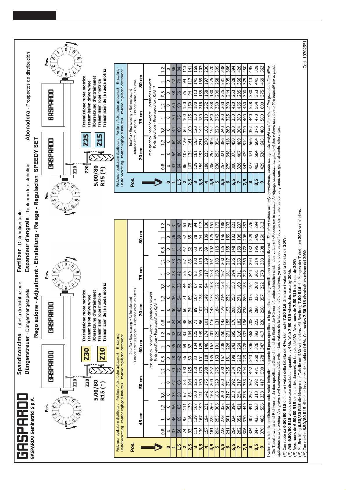
DEUTSCH
3.15.4 SPEEDY SET - Tabelle Kg/Ha
GEBRAUCH UND WARTUNG
84
-
cod. 19501381
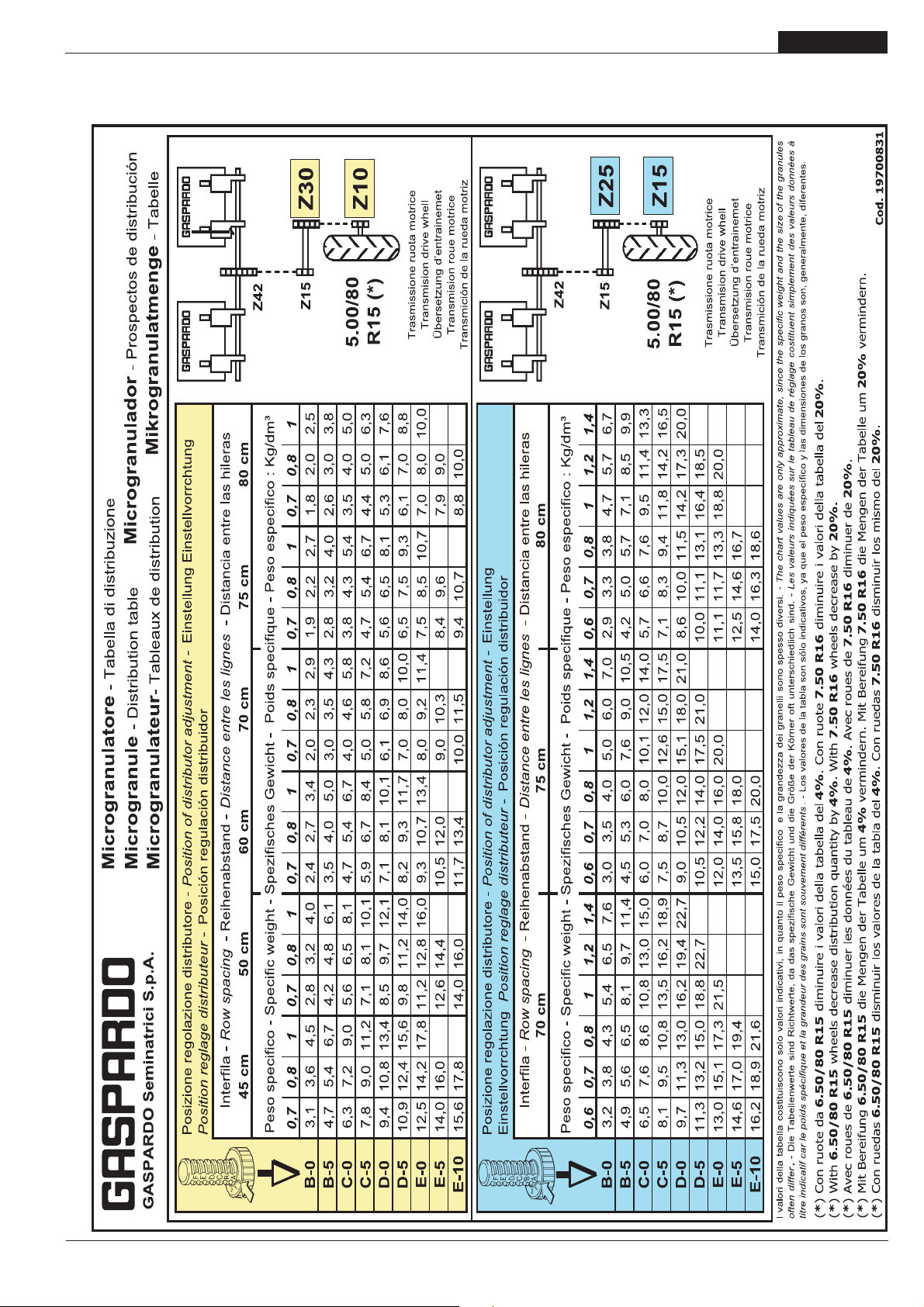
3.15.5 MIKROGRANULATSTREUER - Tabelle Kg/Ha
GEBRAUCH UND WARTUNG
DEUTSCH
cod. 19501381
-
85
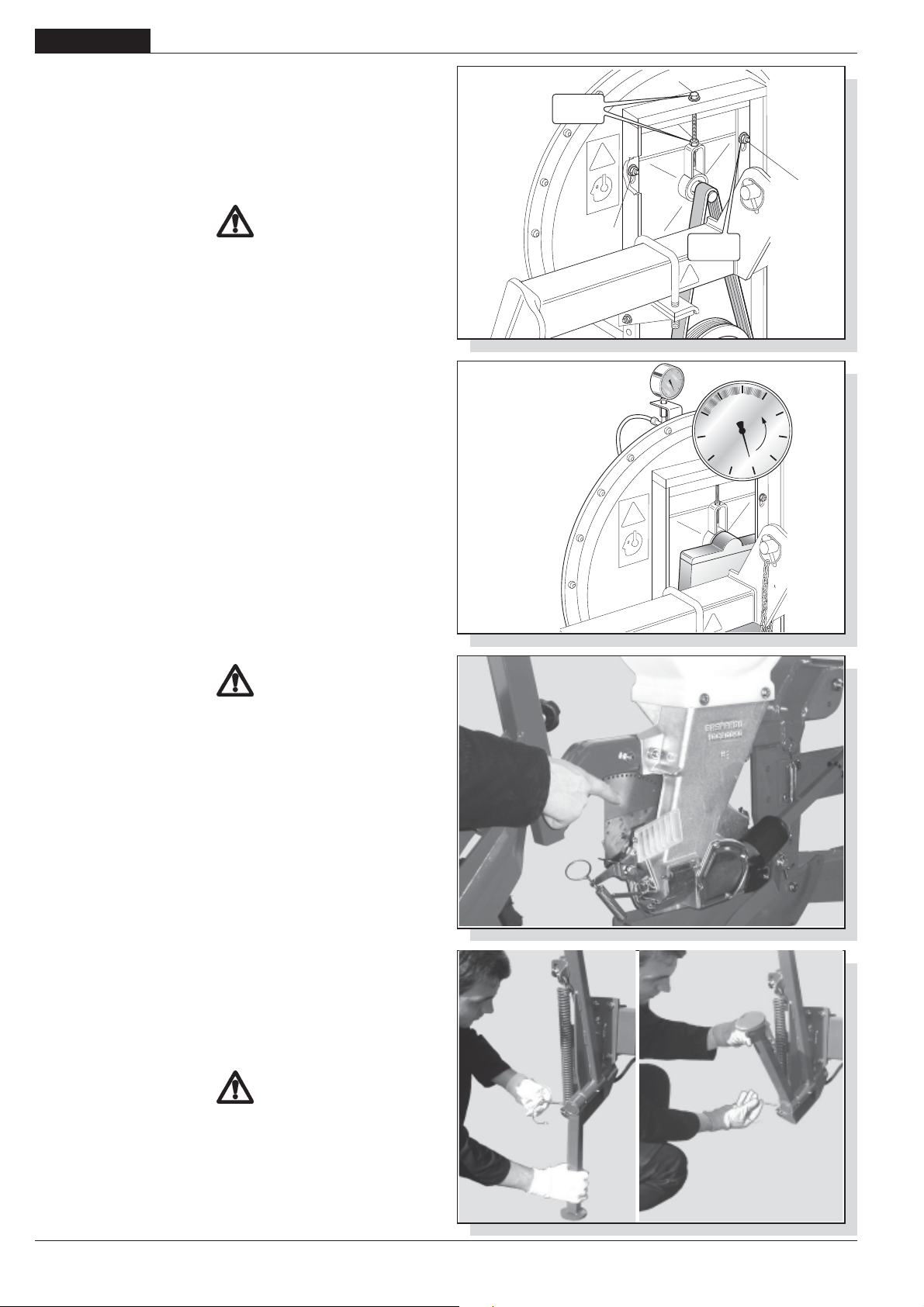
DEUTSCH
GEBRAUCH UND WARTUNG
3.16 VAKUUMPUMPE
Der Ansauger (Abb. 42) bildet ein Vakuum in den Verteilern und
ermöglicht somit, daß die Samen in die Säscheibenlöcher
angesaugt werden. Für die Leistung der Säscheibe und somit
auch für ein einwandfreies Aussäen ist es von grundlegender
Bedeutung, daß der Riemen sich in einem einwandfreien Zustand
befindet. Ein korrekt gespannter Riemen darf nicht nachgeben,
wenn man mit der Hand auf ihn drückt.
ACHTUNG
Sicherstellen, dass die Kardanwelle an die Antriebswelle
angeschlossen ist, bevor die nachstehenden Eingriffe
ausgeführt werden:
Riemenkontrolle:
- Das Schutzgehäuse abnehmen
- Die 4 Schrauben lockern (1, Abb. 42)
- Die Mutter lockern (2, Abb. 42)
- Einen verschlissenen Riemen sofort auswechseln
- Den Riemen spannen, indem die Schraube festgezogen wird
(3, Abb. 43).
- Alle zuvor gelockerten Schrauben wieder festziehen und das
Schutzgehäuse wieder anbringen.
Vakuummesser
Der Vakuummesser (Abb. 43) mißt das Vakuum. Der
mitgelieferte Vakuummesser zeigt Ansaugwerte zwischen -0 und
-100 mbar an. Die durchschnittlichen Richtwerte für große Samen
sind: -60 ÷ -70 mbar für kleine Samen -40 ÷ -50 mbar.
Die angegebene Drehzahl der Zapf-welle beachten.
NR -
17
3
2
1
1
NR -
-70
-80
19
-60
-90
-100
-50
Mbar
fig. 42
-40
-30
-20
-10
0
3.17 VORBEREITUNGEN FÜR DIE AUSSAAT
Es ist sehr wichtig, dass die Sämaschine korrekt auf dem Feld
eingestellt wird.
GEFHAR
Es ist ausschließlich die folgende Beschreibung und
Arbeitssequenz zu befolgen:
- Die Sämaschine vom Fahrersitz des Schleppers aus
hochfahren;
- Die Zapfwelle mit 540 UpM laufen lassen;
- Den Schleppermotor mit dem Kupplungshebel auf Leerlauf
stellen;
- Den Schlepper abbremsen und ihnwenn nötigdurch geeignet
große Bremskeile unter den Rädern blockieren;
- Sicherstellen, daß sich niemand dem Fahrerplatz des
Schleppers nähern kann;
- Kontrollieren, daß alle Antriebswellen einwandfrei eingekuppelt
sind;
- Die beweglichen Teile, die Antriebsund Saatgustreuorgane -
Die Saatguttrichter entleeren: Es wird darauf hingewiesen, dass
zum Heben von Gewichten über 30 kg mehrere Personen
benötigt werden oder dass das oben beschriebene
mechanische Hubwerk verwendet werden muss, wobei die in
dem Betriebs- und Wartungshandbuch desselben enthaltenen
Anleitungen zu befolgen sind.
fig. 43
fig. 44
ACHTUNG
Alle Eingriffe müssen von Fachpersonal, dass über geeignete
Schutzausrüstungen (Arbeitsanzug, Handschuhe, Stiefel,
Masken, usw.) verfügt, in einer sauberen nicht staubhaltigen
Umgebung durchgeführt werden. Aufpassen, dass beim Befüllen
der Saatguttrichter und der Düngemittel- und
Insektenschutzmittelbehälter keine Fremdkörper (Seile,
Verpackungsteile, usw.) in die Behälter oder Trichter gelangen.
86
-
fig. 45
cod. 19501381
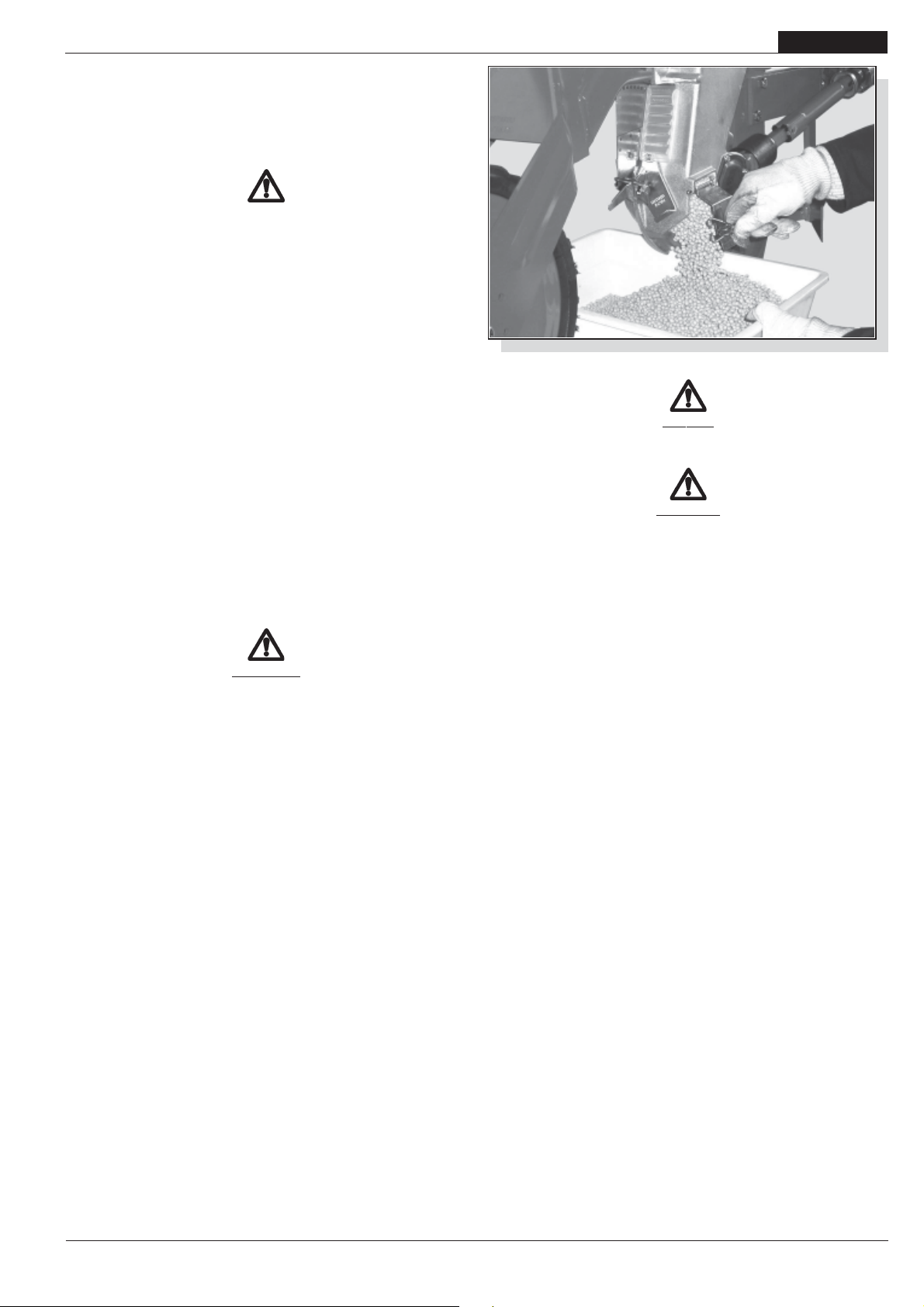
GEBRAUCH UND WARTUNG
- Das Rad, das die Bewegung auf das Getriebe der Sämaschine
überträgt, per Hand in Laufrichtung drehen;
- Den Wähler einstellen und am durchsichtigen Gitter (Abb. 44)
prüfen, daß die Scheibe nur einen Samen pro Loch trägt.
- Aus der Saatguttabelle auf Seite 77 kann man vor der Aussaat
entnehmen, wieviel Saatgut benötigt wird.
VORSHICHT
Die Stützfüsse entfernen und umklappen (Fig. 45).
- Mit der Aussaat fortfahren: Nach einigen Metern prüfen, daß die
Säapparate nur jeweils einen Samen ablegen.
Am Ende der Aussaat die restlichen Samen durch die Öffnung
des Säaggregats entleeren (Abb. 46).
3.18 WÄHREND DER AUSSAAT
- Jede Treibwelle ist mit einem Drehmomentbegrenzer mit Sirene (5 Abb. 29) ausgerüstet, die bei einem Bruch des Stiftes (3
Abb. 29) anspricht und die am Säaggregat aufgetretene Anomalie oder Störung anzeigt. In diesem Fall ist die Maschine
sofort anzuhalten und die Störung zu beheben, den
gebrochenen Stift entfernen und ersetzen (den mitgelieferten
Stiftzieher verwenden).
- Am Ende jedes Laufes während der Rückfahrt die Zapfwelle
immer auf einer Drehzahl halten, die ausreicht, damit die
Samen an den Streuerscheiben hängenbleiben.
- Während der Aussaat öfters die Samenstreuung prüfen; falls
diese nicht genau ist, den Wähler einstellen;
- Bei fehlender oder mangelhafter Ansaugung prüfen, daß die
Rohre keine Leckagen aufweisen und daß sie nicht verstopft
sind. In diesem Fall sind die Rohre auszuwechseln oder zu
reinigen; eventuell auch den Gebläseriemen kontrollieren.
DEUTSCH
fig. 46
GEFAHR
Die Sämaschine kann chemische Stoffe befördern. Personen,
Kindern und ist der Zutritt zur Sämaschine zu untersagen.
ACHTUNG
Auf keinen Fall Düngersäcke oder andere Gegenstände auf
die Deckel der Düngerstreukästen legen, um deren
Beschädigung sowie Personen und Sachschäden zu
verhindern. Von den Aussenflanken aus auffüllen.
Der Zugang zu den Behältern mit den chemischen Stoffen ist
allen Personen untersagt; es ist außerdem verboten diese zu
öffnen, wenn die Sämaschine in Betrieb ist oder gerade in
Betrieb gesetzt wird.
VORSICHT
- Die Form, die Abmessungenund das Material der
Spannhülsen der Antriebswellen wurden als
Sicherheitsmaßnahme verwendet. Der Einsatz von nicht Originaloder widerstandsfähigeren Spannhülsen kann
schweren Schaden an der Sämaschine hervorrufen.
- Die Zapfwelle stufenweise anlassen; ein abruptes Anlassen
verursacht Schäden am Gebläseriemen.
- Bei in der Erde fahrender Maschine sind Kurven zu vermeiden;
nie im Rückwärtsgang arbeiten. Die Maschine bei
Fahrtrichtungswechsel und beim Umkehren immer heben.
- Nicht bei synchron mit den Rollen laufender Zapfwelle
arbeiten.
- Nicht die für die Zapfwelle angegebene Drehzahl
überschreiten.
- Den Schlepper nie auf die höchste Drehzahl beschleunigen.
- Es ist eine mit dem Bearbeitungstyp des Bodens vereinbare
Sägeschwindigkeit anzuwenden, um Bruch und
Beschädigungen zu vermeiden.
- Die Sämaschine bei sich bewegendem Schlepper absenken,
um eine Beschädigung oder Verstopfung
der Säscharen zu vermeiden: aus dem gleichen Grund ist
vom Rückwärtsfahren mit auf dem Boden liegender
Sämaschine abzuraten.
- Beim Einfüllen der Samen, Düngemittel und
Schädlingsbekämp fungsmittel in die entsprechenden
Behälter ist darauf zu achten, daß keine anderen Körper
eintreten (Schnüre, Sackpapier, usw.).
cod. 19501381
-
87
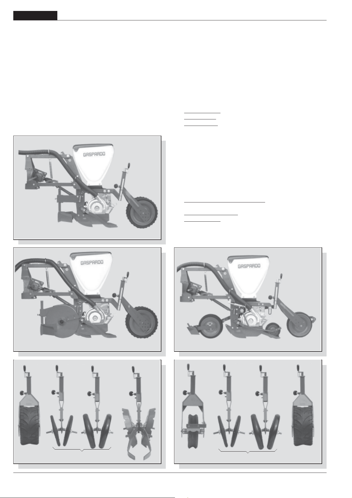
DEUTSCH
GEBRAUCH UND WARTUNG
3.19 AUSFÜHRUNGEN
Bei allen Modellen sind die Säaggregate mittels Mechanismen
mit Gelenk-Parallelogramm einzeln an den Rahmen
angeschlossen, obwohl einige spezifische Besonderheiten je
nach auszustreuendem Saatgut und den jeweiligen
Bodeneigenschaften vorhanden sind.
a) Säaggregate für Tiefenaussaat
Es werden zwei verschiedene Säaggregattypen für eine
mitteltiefe und tiefe Aussaat je nach Beschaffenheit des
Saatbeetes angeboten:
- Auf sorgfältig vorbereiteten feinen Böden sind Säscharren mit
Klutenräumern und Druckrolle (Abb. 47) einzusetzen;
- Auf gröberen Böden sowie bei Rückständen ist es dagegen
angebracht, Ausrüstungen mit doppelter Scheibe oberhalb
der Säscharre einzusetzen, auf die Druckrollen folgen (Abb.
48);
Die Furchenabdeckelemente werden je nach
Bodeneigenschaften in 3 verschiedenen Ausführungen
angeboten (Abb. 49):
Farmflex-Rolle (Ø=370mm) für feuchte und sandige Böden;
1)
2) V-Druckrollen aus Gummi für feuchte und Problemböden.
3) V-Druckrollen aus Eisen für mittelschwere und trockene
Böden;
b) Säaggregate für Oberflächenaussaat
Das Säaggregat für die Oberflächenaussaat verfügt über einen
Standard-Tandemwagen mit Gummirädern: Auf das vordere
Klutenbrechrad mit gewölbtem Profil (Ø=280 mm) folgt die
Samenandrückrolle aus Gummi, mit unabhängigen Zustreifern
(Abb. 50).
Die Furchenzustreifer werden je nach Bodeneigenschaften in 3
verschiedenen Ausführungen angeboten (Abb. 51):
fig. 47
fig. 48
fig. 49
1) Gummirolle mit konkavem Profil (Ø=290 mm), speziell für
Rüben;
2) "V"-Rollen aus Gummi für feuchte Böden und Problemböden;
3) Farmflex-Rolle (Ø=370 mm) für feuchte und sandige Böden.
fig. 50
fig. 51
88
1
2
3
-
1
2
3
cod. 19501381
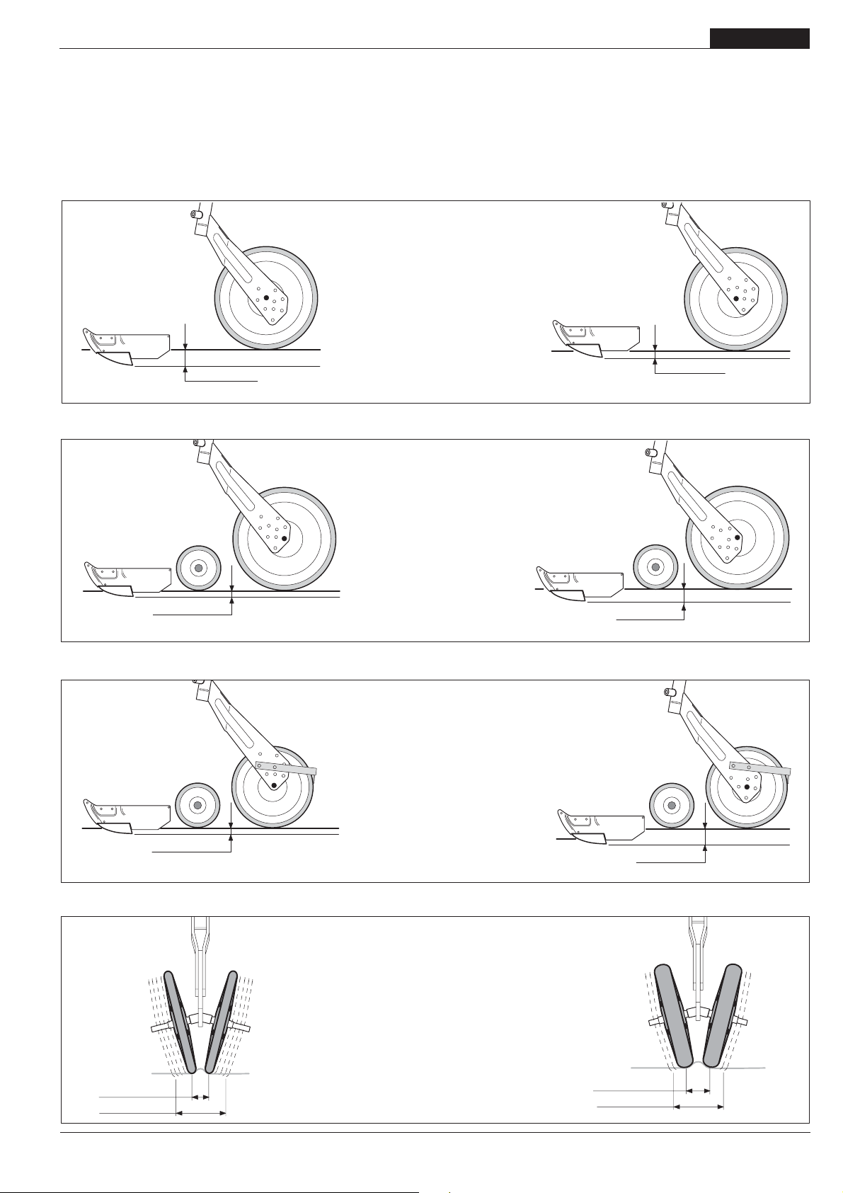
GEBRAUCH UND WARTUNG
DEUTSCH
EINSTELLEN DER HINTEREN DRUCKROLLEN
Von großer Bedeutung ist beim Qualitätssäen die hintere
Ausstattung der Säaggregate.
Die Säaggregate bestimmen die Sätiefe und das Zustreichen
des Saatguts nach dem Aussäen.
RUOTA FARMFLEX 370 mm
Semine medio profonde
(mais, girasole, soia)
max 10 cm
RUOTA FARMFLEX 370 mm
Semine superficiali
(barbabietole)
Daher sind die Säaggregate präzise bezüglich des jeweiligen
Saatgut- und Bodentyps einzustellen, indem die Position der
Hinterräder auf ihrer Halterung wie auf dem nachstehenden Schema dargestellt geändert wird.
max 7 cm
max 3,5 cm
max 3,5 cm
max 5 cm
RUOTA IN GOMMA
A PROFILO CONCAVO 290 mm
Semine superficiali
(barbabietole)
max 5 cm
RUOTE A V IN GOMMA
1 - 2
max 4,5 cm
max 14 cm
cod. 19501381
-
max 6,5 cm
max 11 cm
89

DEUTSCH
GEBRAUCH UND WARTUNG
4.0 WARTUNG
Hier folgend sind die verschiedenen, regelmässig
auszuführenden Wartungsarbeiten aufgeführt. Die geringeren
Betriebskosten und die lange Lebensdauer des Geräts hängen
unter anderem von der ständigen Beachtung dieser Vorschriften
ab. Dank des Einrostanschlußsystems, praktisch und sicher,
kann die Sämaschine für Wartungsarbeiten und Kontrollen (Abb.
15) gehoben werden.
VORSICHT
- Die Zeitabstände, die für die Durchführung der Wartungsarbeiten angegeben sind, sind nur Richtwerte und beziehen
sich auf normale Einsatzbedingungen. Sie können daher je
nach Arbeits-weise, mehr oder weniger staubiger Umgebung,
jahreszeitliche Faktoren, usw. schwanken. Im Fall von
schwierigeren Arbeitsbedingungen müssen die
Wartungseingriffe häufiger durchgeführt werden.
- Vor Einspritzen von Fett in die Schmiernippel müssen diese
sorgfältig gereinigt werden, um zu vermeiden, daß sich
Schlamm, Staub oder Fremdkörper mit dem Fett mischen,
wodurch die Schmierwirkung verringert oder sogar
aufgehoben würde.
ACHTUNG
- Öle und Fette immer ausserhalb der Reichweite von Kindern
aufbewahren.
- Die auf den Behältern und in den Sicherheitskarten der
Produkte aufgeführten Warnungen und
Vorsichtsmaßnahmen sind immer aufmerksam zu lesen.
- Kontakt mit der Haut vermeiden.
- Nach Gebrauch die Hände sorgfältig und gründlich waschen.
- Altöl und umweltverschmutzende Flüssigkeiten laut den
geltenden Umweltschutzgesetzen entsorgen.
4.0.1 BEI NEUER MASCHINE
- Nach den ersten acht Betriebsstunden den Anzug aller
Schrauben prüfen.
4.0.2 BEI BEGINN DER AUSSAATSAISON
- Die Sämaschine leer anlassen, der Luftdurchfluss befreit die
Leitungen von Kondenswasser und entfernt eventuelle
Fremdstoffe.
fig. 52
3
1
6
4
2
5
90
-
cod. 19501381

GEBRAUCH UND WARTUNG
4.0.3 ALLE 8 BETRIEBSSTUNDEN
- Die Kreuze der Gelenkwelle schmieren.
- Den Bolzen der Spurreisserscheiben (1 Abb. 52) schmieren.
- Falls die “V” Rollen aus Eisen montiert sind, die Naben (3 Abb.
52) schmieren.
- Die Spannung der Gebläseriemen (Abb. 42) schmieren.
DEUTSCH
ACHTUNG
Alle für das Verschrotten erforderlichen Aus- und
Abbauarbeiten müssen bei stillstehender und vom Schlepper
abgekoppelter Maschine vorgenommen werden.
4.0.4 ALLE 50 BETRIEBSSTUNDEN
- Den Zustand der Lochscheiben prüfen, falls Sprossen fehlen
oder sie sind gebogen, die Scheibe mit einem Originalersatzteil
wechseln.; eventuelle kreisförmige Schlierenbildungen dürfen
nicht 1/3 der Scheibenstärke überschreiten.
- Das Innere des Säapparats mit Wasser und Benzin reinigen,
eventuell die Deckeldichtung wechseln.
- Den Bolzen des Spurreisserarms schmieren (6 Abb. 52).
4.0.5 ALLE 6 MONATE
- Die Schraube der Höhenregler (2 Abb. 52) ölen.
- Die Pendellager der Antriebsräder (4 Abb. 52) fetten.
- Die Antriebsübersetzung der Gelenkwellen (5 Abb. 52)
schmieren.
4.0.6 RUHEPERIODEN
Am Ende der Saison oder wenn eine lange Ruhezeit vorgesehen
ist, wird folgendes empfohlen:
- Das Gerät mit viel Wasser waschen, besonders die
Chemikalienbehälter, dann trocknen.
- Die beschädigten oder verschleissten Teile genau prüfen und
eventuell wechseln.
- Den Riemen der Vakuumpumpe einstellen und eventuell
wechseln.
- Alle Schrauben und Mutterschrauben gut anziehen.
- Die Antriebsketten schmieren, alle Antriebsketten ölen und alle
nicht angestrichenen Teile mit Schmierstoff einstreichen.
- Das Gerät mit einer Plane schützen.
- Dann das Gerät in einem trockenen Raum fest und ausser der
Reichweite der nicht Zuständigen lagern.
Die sorgfältige Ausführung dieser Arbeiten ist einzig zum Vorteil
des Verbrauchers, da er bei Wiederaufnahme der Arbeit sein
Gerät in einwandfreiem Zustand vorfinden wird.
4.0.7 EMPFOHLENE SCHMIERMITTEL
- Zur Schmierung wird allgemein empfohlen: ÖL AGIP BLASIA
460 SAE 85W/140 oder gleichartigens, für Einzelangaben siehe
letzte Deckseite.
- Für alle Fettpunkte wird empfohlen: FETT AGIP GR MU EP 2
oder gleichartigens, für Einzelangaben siehe letzte Deckseite.
5.0 ZERLEGEN UND ENTSORGEN DER
MASCHINE
Für das Zerlegen und Entsorgen der Maschine hat der Kunde zu
sorgen. Vor dem Verschrotten der Maschine ist der Zustand der
Maschine genau zu überprüfen und sicherzustellen, dass keine
Gerüstteile vorhanden sind, die beim Zerlegen
auseinanderbrechen oder nachgeben könnten.
Der Kunde hat die im jeweiligen Anwendungsland der Maschine
geltenden Umweltschutzgesetze zu beachten.
Vor dem Zerlegen der Maschine sind alle eine Gefahr
darstellenden Teile unschädlich zu machen, d.h.:
- das Gerüst durch Fachunternehmen verschrotten lassen,
- eventuelle elektrische Geräte gemäß den geltenden Gesetzen
entsorgen,
- Öl und Fett getrennt sammeln und von zugelassenen
Unternehmen gemäß den im Anwendungsland der Maschine
geltenden Vorschriften entsorgen lassen.
Beim Verschrotten der Maschine ist das CE-Zeichen zusammen
mit dem vorliegenden Handbuch zu vernichten.
6.0 LIEFERUMFANG
Serienausstattung:
- Gebrauchs- und Wartungs-anleitungen;
- Ersatzteile-anleitungen;
- Gelenkwelle;
- Mit Schlepperscheibe für Zapfwelle bei 540 UpM.
- Eine Serie Aussaatscheiben;
- Spuranzeiger;
- Nr. 4 Zahnräder (2 montiert) für den Antrieb des Getrieberads;
- Stiftezieher;
- Nr. 10 Sicherheitsstifte für den GelenkwellenDrehmomentbegrenzer der Säapparate;
- Nr. 4 Zahnräder (2 montiert) für den Antrieb des Dünger- und/
oder Mikrogranulatstreuers (falls mit der Maschine geliefert);
- Serie Sichtsignale (Hinterlichter).
Ausstattung auf Anfrage: Die Sämaschine kann mit folgendem
ausgestattet werden:
- Säscharenreisser mit Doppel-scheibe;
- Version mit Kipphebel;
- Mit elektronischem Hektarzähler;
- Mit Monitor zur Samenkontrolle;
- Mit festem Klotenräumer;
- Mit Automatischer Spuranzeiger;
- Mit 370 mm Gummidruckrollen;
- Mit 290 mm hohler Druckrolle aus Gummi komplett mit kleiner
Samendruckrolle
- Mit “V”- förmige Stahldruckrolle oder Gummidruckrollen;
- Mit 6.50/80x15 Antriebsrädern;
- Mit Freirad-Doppelantrieb;
- Mit Doppelpaar Spurhacke
- Mit Schlepperscheibe für Zapfwelle bei 1000 UpM.
Am Ende dieser Anleitungen möchte der Hersteller daran
erinnern, daß er für alle Fragen bezüglich Kundendienst und
Ersatzteile immer zur Verfügung steht.
ACHTUNG
Die Maschine darf nur von Fachmännern in ihre Einzelteile
zerlegt werden. Dieses Fachpersonal muss über die
erforderlichen individuellen Schutzmittel (Sicherheitsschuhe
und Schutzhandschuhe), Werkzeuge und Hilfsgeräte verfügen.
cod. 19501381
-
91

Notes
92
-
cod. 19501381

Notes
cod. 19501381
-
93

94
-
cod. 19501381

1.0 INTRODUCTION
FRANÇAIS
Cette brochure décrit les normes d’utilisation, d’entretien pour
le semoir.
Cette brochure, qui fait partie du produit, doit être conservé dans
un endroit sûr et consulté pendant toute la durée de la machine.
Le client devra informer le personnel des risques d'accident,
des dispositifs prévus pour la sécurité de l'opérateur, des risques
d'émission de bruit et des règles générales de prévention des
accidents prévues par les directives internationales et par la
législation du pays de destination des machines.
Dans tous les cas, la machine doit être exclusivement utilisée
par des opérateurs qualifiés qui seront tenus à respecter
scrupuleusement les instructions techniques et de prévention
des accidents, contenues dans le présent manuel.
L'utilisateur doit s'assurer que la machine est actionnée
uniquement dans des conditions optimales de sécurité tant pour
les personnes, que pour les animaux et les biens.
Le produit est conforme aux Normes Européennes suivantes:
- 98/37 CE Directive Machines qui abroge et comprend les
Directives 89/392 CEE, 91/368 CEE, 94/44 CEE et 93/68 CEE.
- 89/336 CEE (Concernant le rapprochement des législations
des états membres, relatives au matériel électrique destiné à
être utilisé dans certaines limites de tension).
Pour l'adaptation de la machine, les normes suivantes ont été
utilisées:
- EN 292-1 : 1992 (Sécurité de l'outillage) Concepts
fondamentaux, principes généraux de conception. Terminologie, méthodologie de base.
- EN 292-1 A/1 : 1992
- EN 292-2 : 1992 (Sécurité de l'outillage) Concepts
fondamentaux, principes généraux de conception.
Spécifications et principes techniques.
- EN 294 : 1993 (Sécurité de l'outillage) Distances de sécurité
pour empêcher l'accès à des zones dangereuses avec les
membres supérieurs.
- EN 982 : 1997 (Sécurité de l'outillage) Exigences de sécurité
relatives aux systèmes et leurs composants pour les
transmissions oléohydrauliques et pneumatiques.
- EN 1553 : 1999 (Machines agricoles) Machines agricoles
autotractées, portées, semiportées et tractées - Exigences
communes de sécurité.
- pr EN 144045 (Semoirs - Sécurité) document CEN/TC 144 WG
3 n. 347 - édition mai 2000.
1.1 DESCRIPTION DE LA MACHINE
Cet équipement agricole, appelé “Semoir Pneumatique”, ne peut
travailler que par un arbre à cardans appliqué à la prise de force
d’un tracteur agricole doté d’un groupe élévateur, avec un attelage
universel en trois points. L’équipement est particulièrement
indiqué pour des ensemencements de précision, pour des
emplois polyvalents et avec n’importe quel type de graine sur
des sols travaillés. Le semoir pneumatique peut être doté de
différents accessoires, par exemple le distributeur d’engrais, le
microgranulateur et d’autres éléments d’ensemencement.
La conception “modulaire” fondamentale a été élaborée et
associée à l’idée de “simplicité” du point de vue de la construction
et de l’utilisation pratique.
ATTENTION
Le semoir n’est indiqué que pour des ensemencements au
sol. La vitesse de travail conseillée est d'environ 6-8 km/h. Le
transport sur route du semoir doit s'effectuer avec les trémies
et réservoirs vides, et à une vitesse maximale de 25 km/h. Un
emploi autre que celui qui est décrit dans ces instructions
peut endommager la machine et représente un grave danger
pour l’usager.
Le fonctionnement régulier de l’équipement dépend de son
utilisation correcte et de son entretien adéquat. Nous conseillons
donc de respecter scrupuleusement les instructions pour éviter
tout inconvénient qui pourrait compromettre le bon fonctionnement
et la durée de l’équipement. Toutes les informations pour le
meilleur usage de la machine, ainsi que les instructions et les
conseils utiles pour un entretien correcte sont également fournis.
Il est aussi important de respecter les instructions de cette
brochure parce que la Maison Constructrice décline toute
responsabilité due à négligence et au non respect de ces
normes. La Maison Constructrice demeure à Votre entière
disposition pour garantir une assistance technique immédiate
et soignée et tout ce qui peut être nécessaire pour le meilleur
fonctionnement et le rendement maximim de l’équipement.
1.2 GARANTIE
- Au moment de la livraison de votre machine vérifiez si elle n’a
pas été endommagée pendant le transport et si tous les
accessoires sont en bon état.
- Les réclamations éventuelles devront être présentées par
écrit dans un délai de 8 jours à compter de la réception.
- L’acheteur ne pourra faire valoir ses droits de garantie que s’il
a respecté les conditions correspondantes, indiquées dans le
contrat de fourniture.
- La garantie est valable pour un an contre tout défaut du matériel,
à partir de la date de livraison de l’équipement.
- La garantie ne comprend pas les frais de main-d’oeuvre et
d’expédition (le matériel est transporté aux risques et périls du
destinataire)
- La garantie exclut naturellement tous les dommages subis
par des personnes ou des choses.
- La garantie est limitée au dépannage ou au remplacement
gratuit de la pièce défectueuse, selon les instructions du
Constructeur.
Les revendeurs ou les usagers ne pourront prétendre aucune
indemnisation par le Constructeur pour tout dommage qu’ils
pourront subir (frais de main-d’oeuvre, transport, travail
défectueux, accidents directs ou indirects, manque à gagner sur
la récolte etc.).
1.2.1 EXPIRATION DE LA GARANTIE
Les conditions du contrat de garantie demeurant valables, la
garantie est supprimée dans les cas suivants:
- En cas de dépassement des limites indiquées dans le tableau
des données techniques.
- Si l’on n’a pas respecté soigneusement les instructions décrites
dans cette brochure.
- En cas de mauvais emploi, d’entretien insuffisant et en cas
d’autres erreurs effectuées par le client.
- En cas de modifications apportées sans l’autorisation écrite
du constructeur et en cas d’utilisation de pièces détachées qui
ne sont pas d’origine.
cod. 19501381
-
95

FRANÇAIS
(A)
EMPLOI ET ENTRETIEN
1.3 DONNES TECHNIQUES U.M.
Largeur de ch ssis
Ecartement
CapacitØ de la tremie
semence
m
feet
cm
inch
l.
CapacitØ de engrais l.
Prise de force tr/mn
Puissance demandØe
Poids (*)
Mesures du niveau sonore
vide
HP
KW
Kg
lb
Lpam (A)
Lwa
4 rangs
cm. 75
2,50
8-2"
75
29
320 320 560 320
60
44
550
1210
5 rangs
cm. 75
3,20
10-5"
60
23
70
51
615
1353
109,7
32
540
92,3
6 rangs
cm. 75
4,20
14"
75
29
90
66
662
1456
6 rangs
cm. 45
2,50
8-2"
45
17
70
51
740
1628
(*) Sans l’Øpandeur d’engrais et microgranulateur.
Les données techniques et les modèles indiqués ne sont pas contraignants. Nous nous réservons le droit de les modifier sans
préavis.
1.4 IDENTIFICATION
Chaque équipement est doté d’une plaque d’identification (18
Figure 2) dont les données indiquent:
- Marque CE;
- Marque du Constructeur;
- Nom, raison sociale et adresse du Constructeur;
- Type de machine;
- Matricule de la machine;
- Anneée de construction;
- Masse en kilogrammes.
Il faudra toujours citer ces données pour l’assistance ou les
pièces détachées demandées.
La masse de la machine apparaît dans la plaque d’identification
(15 Figure 2). Tendre le câble pour niveler la machine.
Les points d’attelage sont identifiés par la présence du symbole
graphique “crochet” (9 Fig. 3). Pour les machines jusqu’à 4
lignes, atteler dans les points A, C et D. Pour les machines avec
plus de 4 lignes, atteler dans les points: A, B, C, D et E.
A
1.5 MOVIMENTATION
En cas de déplacement de la machine, il est nécessaire de la
lever en l'accrochant, aux attaches prédisposées, avec des
câbles en tissu, à l'aide d'un palan ou grue adaptée, d'une
puissance suffisante (Fig. 1). Cette opération, qui est
dangereuse, sera effectuée par un personnel expert et
responsable.
BCDE
fig. 1
96
-
cod. 19501381

EMPLOI ET ENTRETIEN
FRANÇAIS
ELEMENT SEMEUR
MAÏS - TOURNESOL - SOJA
ELEMENT SEMEUR
BETTERAVES
4
5
6
7
8
20
1
23
11
12
15
fig. 2
1.6 DESSIN GLOBAL
1 Disque à tracer
2 Réservoir engrais
3 Aspirateur
4 Vacuomètre
5 Distributeur air
6 Réservoir semences
7 Régulateur hauteur semoir
8 Roue de compression
9 Roue mouve. distributeur d’engrais
10 Distributeur de graines
11 Soc
12 Cardan pour mouvement semoir
13 Pied de support
14 Châssis
15 Plaque d’identification
16 Régulateur distributeur fertilisant (Minimax)
17 Commande disque à tracer
18 Attelage arbre à cardans
19 Support arbre à cardans
20 Comple semences
21 Chasse mottes
13 14
21
16 1718 19
9
10
cod. 19501381
-
97

FRANÇAIS
EMPLOI ET ENTRETIEN
1.7 SIGNAUX DE SECURITE
Les signaux décrits dans la Figure 3 sont indiqués sur la machine.
Nettoyer et remplacer ces signaux s’ils sont détachés ou illisibles.
Lire avec attention la description et mémoriser son sens.
1) Avant de commencer le travail, lire avec attention ce manuel
d’instructions.
2) Avant toute opération d’entretien, arrêter la machine et
consulter le manuel d’instructions.
3) Risque d’écrasement en phase d’ouverture. Maintenir une
distance de sécurité de la machine.
4) Vous risquez d’être pris par l’arbre à cardans. Ne pas
s’approcher des organes en mouvement.
5) Ne vous approchez pas des organes en mouvement: vous
risquez d’y être pris.
6) Risque d’écrasement en phase de fermeture. Maintenir une
distance de sécurité de la machine.
7) En cas d’utilisation de produits anticryptogamiques, se munir de protections adéquates.
8) Niveau sonore élevé. Se munir de protections acoustiques
adéquates.
9) Indication des points d’attelage pour le levage.
10) Point de graissage
1234
56
910
78
fig. 2
98
fig. 3
-
DECALCOMANIE AVVERTIMENTO
Cod. 89900500
WARNING STICKERS
ABZIEHBILDER MIT WARNHINWEISEN
DECALCOMANIE
CALCOMANIAS
cod. 19501381
EMPLOI ET ENTRETIEN
FRANÇAIS
2.0 NORMES DE SECURITE ET DE PREVENTION
DES ACCIDENTS
Faire attention au signal de danger quand il apparaît dans cette
brochure.
Les signaux de danger sont de trois niveaux:
DANGER: Ce signal informe que l’exécution incorrecte des
opérations décrites provoque des lésions graves, la mort ou
des risques à long terme pour la santé.
ATTENTION: Ce signal informe que l’exécution incorrecte des
opérations décrites
ou des risques à long terme pour la santé.
IMPORTANT: Ce signal informe que l’exécution incorrecte des
opérations décrites
Lisez attentivement toutes les instructions avant d’utiliser la
machine; en cas de doutes, contacter directement les
techniciens des Concessionnaires de la Maison Constructrice,
qui dècline toute responsabilitè en cas de non- respect des
normes de sècuritè et de prèvention des accidents dècrites ci
dessous.
Normes générales
1) Faire attention aux symboles de danger indiqués dans ce
manuel et sur la machine.
2) Les étiquettes avec les instructions, appliquées sur la
machine, donnent les conseils utiles essentiels pour éviter
les accidents.
3) Respecter scrupuleusement les prescriptions de sécurité
et de prévention des accidents selon les instructions.
4) Evitez absolument de toucher les parties en mouvement.
5) Les opérations et les réglages concernant l’équipement
doivent toujours être effectués lorsque le moteur est arrêté
et le tracteur est bloqué.
6) Il est absolument interdit de transporter des personnes ou
des animaux sur l’équipement.
7) Il est absolument interdit de conduire ou de faire conduire le
tracteur, avec l’attelage de l’équipement, par des personnes
sans permis, inexpérimentées ou ayant des problèmes de
santé.
8) Avant la mise en marche du tracteur et de l’équipement,
contrôler si tous les dispositifs de sécurité pour le transport
et l’utilisation sont dans des conditions parfaites.
9) Avant la mise en marche de l’équipement, vérifier l’absence
de personnes, notamment d’enfants et d’animaux
domestiques autour de la machine. S’assurer d’avoir
toujours une très bonne visibilité.
10) Porter toujours des vêtements appropriés. Eviter absolument
des vêtements amples qui pourraient se prendre dans des
parties rotatives ou en mouvement.
11) Avant de commencer le travail, apprendre à utiliser les
dispositifs de commande et leurs fonctions.
12) Il ne faut commencer à travailler avec l’équipement que si
tous les dispositifs de protection sont dans des conditions
parfaites, installés et en position de sécurité.
13) Il est absolument interdit de rester dans la zone de travail de
la machine et notamment près des organes de mouvement.
14) Il est absolument interdit d’utiliser l’équipement sans les
protections et les couvercles des réservoirs.
15) Avant de quitter le tracteur, abaisser l’équipement attelé au
groupe élévateur, arrêter le moteur, enclencher le frein de
stationnement et enlever la clef d’allumage du tableau de
commande. Personne ne doit s’approcher des substances
chimiques.
16) Ne pas quitter le poste de conduite quand le tracteur est en
peut provoquer des lésions graves, la mort
peut provoquer des dommages à la machine.
marche.
17) Avant la mise en marche de l’équipement, contrôler que les
pieds de support ne se trouvent pas sous la machine et
vérifier l’assemblage et le réglage correct de celle-ci.
Contrôler que la machine soit en parfait état et que tous les
organes soumis à usure et détérioration soient performants.
18) Avant de décrocher l’équipement de l’attelage à trois points,
mettre en position de blocage le levier de commande
élévateur et abaisser les pieds de support.
19) Ne travailler qu’en condition de bonne visibilité.
20) Toutes les opérations seront réalisées par un personnel
expert, muni de gants de protection, dans un endroit propre
et sans poussière.
Attelage au tracteur
21) Atteler l’équipement, selon les instructions, à un tracteur ayant
une puissance et une configuration adéquates par le
dispositif “ad hoc” (élévateur) conforme aux normes.
22) La catégorie des pivots d’attelage de l’équipement doit
correspondre à celle de l’attelage de l’élévateur.
23) Faire attention quand on travaille dans la zone des bras de
levage: c’est une zone très dangereuse.
24) Faire bien attention pendant les phases d’attelage et de
dételage de l’équipement.
25) Il est absolument interdit de se mettre entre le tracteur et
l’attelage pour manoeuvrer la commande de levage de
l’extérieur (Fig. 4).
26) Il est absolument interdit de se mettre entre le tracteur et
l’équipement (Fig. 4) si le moteur est en marche et le cardan
est enclenché. Il n'est possible de s'interposer entre le
tracteur et l'équipement qu'après avoir actionné le frein de
stationnement et avoir inséré, sous les roues, une cale en
bois ou un caillou de blocage de dimensions appropriées.
27) L’attelage d’un équipement supplémentaire au tracteur
entraîne une répartition différente des poids sur les essieux.
Nous conseillons donc d’ajouter du lest spécial dans la partie
antérieure du tracteur pour équilibrer les poids sur les
essieux. Contrôler la compatibilité des performances du
tracteur avec le poids que le semoir transmet sur l’attelage à
trois points. En cas de doute, contacter le Constructeur du
tracteur.
28) Respecter le poids maximum prévu sur l’essieu, le poids
mobile total, les règlements sur le transport et le code de la
route.
Circulation sur route
29) Pour la circulation routière, il faut respecter les normes du
code de la route en vigueur dans le pays en question.
30) Tout accessoire pour le transport sera doté de signaux et de
protections adéquats.
31) N’oubliez jamais que la tenue de route, la capacité de
direction et de freinage peuvent être modifiées
considérablement par des équipements traînés ou portés.
fig. 4
cod. 19501381
-
99

FRANÇAIS
EMPLOI ET ENTRETIEN
32) Dans les tournants, veiller à la force centrifuge du centre de
gravité exercée dans les différentes positions, avec ou sans
équipement. Faire également très attention sur les routes
ou sur les terrains présentant des déclivités.
33) Pour la phase de transport, régler et fixer les chaînes des
bras latéraux de levage du tracteur; contrôler que les
couvercles des réservoirs des semences et de l’engrais
soient bien fermés; bloquer le levier de commande de
l’élévateur hydraulique; accrocher l’elements semoir selon
les indications à la page 96.
34) Effectuer les déplacements sur route avec tous les réservoirs
vides.
35) Tout déplacement hors de la zone de travail sera effectué
avec l’équipement en position de transport.
36) Sur demande, le Fabricant fournit les supports et les plaques
pour la signalisation de l’encombrement.
37) Lorsque les encombrements constitués par des
équipements conduits ou semiconduits cachent la visibilité
des dispositifs de signalisation et d’éclairage du tracteur,
ceux-ci doivent être reproduits de façon adéquate sur les
équipements, en respectant les normes du code de la route
du pays en question. S’assurer que l’installation des phares
fonctionne parfaitement lors de l’utilisation. On rappelle en
outre que la séquence de signalisation correcte des feux
prévoit (Fig. 5):
A- indicateur de position
B- feu de position rouge
C- feu de stop
44) Contrôler souvent et régulièrement la protection de l’arbre à
cardans; elle doit être toujours en parfait état.
45) Avant d’enclencher la prise de force, contrôler que le nombre
de tours corresponde à celui indiqué par la décalcomanie
appliquée sur l’équipement.
46) Avant d’enclencher la prise de force, vérifier l’absence de
personnes ou d’animaux dans la zone de travail; contrôler
que le régime choisi corresponde au régime autorisé. Il ne
faut jamais dépasser la limite maximum prévue.
47) Faire attention au cardan en rotation.
48) Ne pas enclencher la prise de force si le moteur est arrêté
ou synchronisé avec les roues.
49) Débrayer toujours la prise de force quand l’arbre à cardans
est trop ouvert (jamais plus de 10 degrés - Figure 6) et quand
la prise de force n’est pas utilisée.
50) Nettoyer et graisser l’arbre à cardans seulement si la prise
de force est débrayée, le moteur est arrêté, le frein de
stationnement est enclenché et après avoir enlevé la clef.
51) Quand on n’utilise pas l’arbre à cardans, le poser sur le
support prévu à cet effet.
52) Après le démontage de l’arbre à cardans, remettre le
couvercle de protection sur l’arbre de la prise de force.
Entretien en conditions de securite
Pendant les opérations de travail et de maintenance, utiliser
les dispositifs adéquats de protection individuelle:
Arbre a cardans
38) L’équipement attelé ne peut être commandé que par un arbre
à cardans doté des dispositifs de sécurité nécessaires pour
les surcharges et des protections fixées.
39) Utiliser exclusivement l’arbre à cardans prévu par le
Constructeur.
40) L’installation et le démontage de l’arbre à cardans seront
toujours effectués quand le moteur est arrêté.
41) Contrôler soigneusement l’assemblage correct et la sécurité
de l’arbre à cardans.
42) Bloquer la rotation de la protection de l’arbre à cardans par
la chaîne prévue à cet effet.
43) Contrôler soigneusement la protection de l’arbre à cardans,
en position de transport et de travail.ù
A
B
C
fig. 5
53) Ne pas effectuer des travaux d’entretien et de nettoyage sans
avoir débrayé la prise de force, arrêté le moteur, enclenché
le frein de stationnement et bloqué le tracteur avec une cale
ou un caillou aux dimensions adéquates sous les roues.
54) Contrôler périodiquement le serrage et l’étanchéité des vis
et des écrous; serrer le cas échéant. Pour cette opération, il
faut utiliser une clef dynamométrique et respecter la valeur
de 53 Nm pour des vis M10 catégorie résistance 8.8, et 150
Nm pour des vis M14 catégorie résistance 8.8 (tableau 1).
55) Pendant les travaux d’installation, d’entretien, de nettoyage,
d’assemblage etc., avec la machine soulevée, doter
l’équipement de supports adéquats par précaution.
56) Les pièces détachées devront répondre aux exigences
définies par le Constructeur. N’utiliser que des pièces de
rechange originales.
Ta bl ea u 1
fig. 6
100
-
cod. 19501381
 Loading...