

Page 1
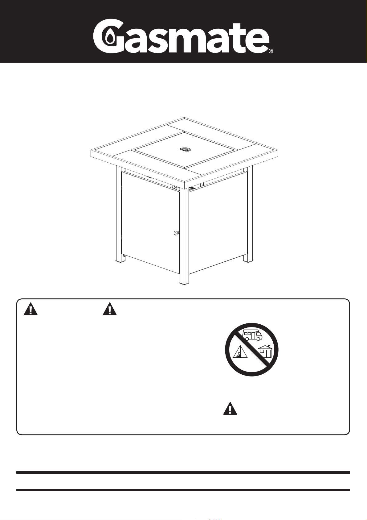
Bastion Gas Fire Table
This appliance can produce
carbon monoxide which has
no odour.
Using it in an enclosed
space, eg. boat, caravan,
tent, car, campervan or
house, may cause death.
CARBON MONOXIDE HAZARD
CARBON MONOXIDE HAZARD
This appliance can produce carbon monoxide
which has no odour.
Using it in an enclosed space, eg. boat, caravan,
tent, car, campervan or house, may cause death.
Model No. GM142-157
DANGER
If you smell gas:
1. Shut off the gas to
the appliance.
2. Extinguish any open
ame.
3. If odour continues,
keep away from
the appliance and
immediately call
your gas supplier or
re department.
WARNING:
Do not store or use gasoline, or other
ammable vapors and liquids, in the
vicinity of this or any other appliance.
An LPG Cylinder not connected for use
shall not be stored in the vicinity of this
or any other appliance.
Improper installation, adjustment,
alteration, service or maintenance
can cause injury or property damage.
Read the installation, operating, and
maintenance instructions thoroughly
before installing or servicing this
equipment.
Retain these instructions for future use.
CARBON MONOXIDE HAZARD
Never use this appliance in an enclosed
space such as a camper, tent, car or home.
WARNING:
For Outdoor Use Only
This appliance can
produce carbon
monoxide which has
no odor.
Using it in an
enclosed space can
kill you.
Important: The installer or seller must leave these instructions with the consumer.
5074-02/19
Page 2

Installation, Operation and Maintenance Instructions
INSTALLATION
Important Safety Rules:
This appliance must only be used in a well ventilated
area.
1. This appliance shall not be installed or used indoors,
in buildings, garages or any other enclosed area.
2. ALWAYS place the appliance on a rm and level
surface.
3. DO NOT place articles on or against this appliance.
4. DO NOT use or store ammable materials near this
appliance.
5. DO NOT use in windy conditions.
6. DO NOT burn solid fuels in the appliance.
7. This is a decorative appliance only and any kind of
cooking is strictly forbidden.
8. Children and adults should be alerted to the hazards
of high surface temperatures, burns and clothing
ignition.
9. Children should be carefully supervised when they
are in the area of the appliance.
10.NEVER hang anything including clothes or other
ammable items on the appliance.
11.DO NOT use this appliance if any part has been
under water. Immediately call a qualied service
technician to inspect the appliance and to replace
any part of the control system and any gas control
that has been under water.
12.DO NOT operate this appliance unless it is fully
assembled.
13.DO NOT SPRAY AEROSOLS IN THE VICINITY OF
THIS APPLIANCE WHILE IT IS IN OPERATION.
14.Before use: Remove any debris from within the
grate area.
15.Installation and repair should be done by a qualied
service person. The appliance must be inspected
before use and at least annually by a qualied
service person. More frequent cleaning may be
required as necessary. It is imperative that control
compartment, burners and circulating air passages
of the appliance and light be kept clean.
Prior to assembling your appliance, the following must be
reviewed. Compliance with the following should result in
satisfactory appliance operation. This instruction manual
should be retained for future reference. The installation
must conform with local codes or authority having
jurisdiction.
1. The appliance is intended for residential and
nonresidential outdoor spaces. The installation
must conform with New Zealand Standard 5601
“Gas Installations”.
2. Adequate clearance around air openings into the
combustion chamber, clearances from combustible
materials, provisions for accessibility and for
combustion and ventilating air supply must be
maintained at all times when the appliance is operating.
2 3
3. Proper clearance from combustible materials must be
maintained at all times. The minimum clearances are
as follows:
Minimum Clearance from Combustibles:
Sides 1000 mm Above 1500 mm
DO NOT locate this appliance under any overhead
enclosure. Avoid using near or under overhanging trees
and shrubs. Combustible materials should never be within
3m of the top of the appliance.
Combustible materials are considered to be wood,
compressed paper, plant bres, plastic, plexiglas or
other materials capable of being ignited and burned.
Such materials shall be considered combustible even
though ame proofed, re-retardant treated or plastered.
Additional clearance may be required for glass, painted
surfaces and other materials which may be damaged by
radiant or convection heat.
4. The appliance must be placed on a non-combustible
level and adequate footing and be readily accessible.
5. The gas manifold supply pressure must be regulated
at 2.75 kPa utilising an approved regulator
(supplied with appliance).
6. The appliance must be inspected before each use, and
at least annually by a qualied service person.
a. The appliance area must be kept clear and free of
combustible materials, gasoline and other
ammable vapours and liquids.
b. Gas orices and burner must be kept clear of dirt
and cobwebs. Flow of combustion and ventilation
air through the perforated portions of the appliance
must not be obstructed. Cleaning with a soft
brush before use and at least every six months is
recommended.
c. All gas connections should be checked for leaks
utilising a soap solution. Never use a ame for this
purpose.
d. The ame pattern at the emitter grid should be
visually checked whenever the appliance is
operated. If black soot is accumulating on the
lava rocks, the appliance should be turned off
immediately. The appliance should not be operated
again until the unit is serviced and or repaired.
e. Any cleaning agent used on the appliance should be
of a non-combustible and non-corrosive nature.
Warm soapy water is ideal. While washing the
appliance, be sure to keep the area around the
burner and pilot assembly dry at all times. If the
gas control is exposed to water in any way, do NOT
try to use it. The appliance should be regularly
cleaned and protected to reduce oxidation, ideally a
cover should be used when not in use.
Page 3
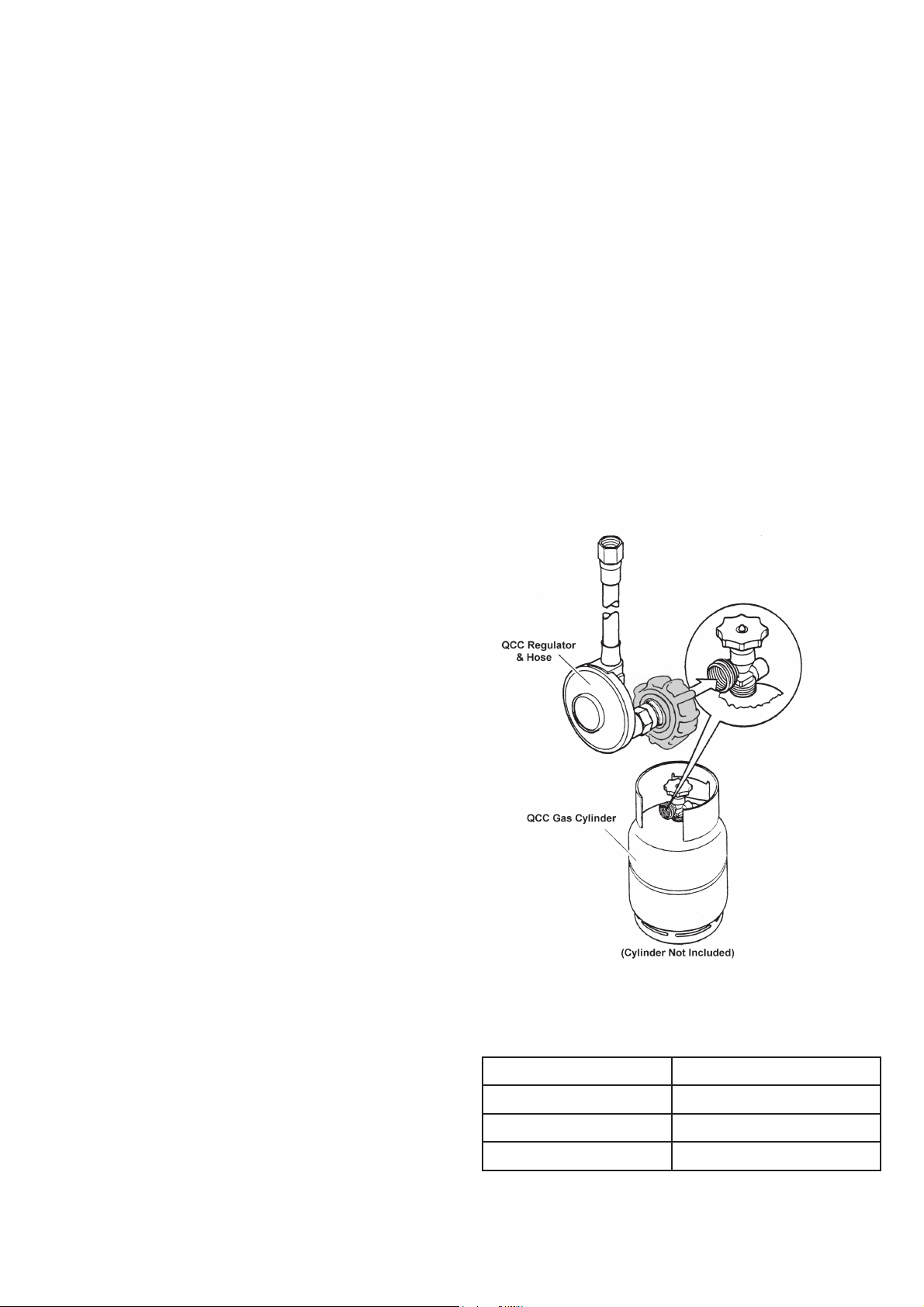
Q.C.C. CYLINDER CONNECTION DEVICE
7. The hose assembly should be properly located out of
pathways where people may trip over it. The hose
must be protected from contact with hot or sharp
surfaces both during use and while in storage. The
hose assembly should be visually inspected prior to
each use of the appliance. If excessive abrasion or
wear is evident, or the hose is cut, it must be
replaced prior to operating the appliance. The
replacement hose assembly may be obtained from
the distributor.
8. DO NOT use any pressure regulator or hose
assembly other than those supplied with the
appliance. Replacement pressure regulator and hose
assembly must be those specied. Replacement parts
may be obtained from the distributor.
9. Installation and use of this appliance must conform
with New Zealand Standard 5601 “Gas Installations”.
10. This appliance is designed to operate with a standard
9Kg LPG cylinder to DOT 4BA-240 with Approved
Cylinder Connection.
11. The valve outlet must be maintained in good
condition. When the cylinder is not in use, be sure to
cover it with a dust cap. A leak test should be
performed with soapy water whenever connecting
a new cylinder. NEVER use a ame to test for leaks.
5. Reconnect the regulator to the gas cylinder.
6. Leak test the connection using a soapy water solution.
Ensure no bubbles appear before proceeding.
7. Slowly open the gas cylinder valve all the way. Do not
put excessive force on the valve at the full open
position, to avoid damaging the valve.
8. Light the appliance as per the instructions provided.
Any modication to the appliance not described in the
installation instructions may compromise the safety of
this appliance. Special concern is as follows:
(1) DO NOT bypass thermocouple safety burner;
(2) DO NOT operate appliance without the grate
in place;
Clothing or other ammable materials should not be hung
from the appliance, or placed on or near the appliance.
The area above the burner may be extremely hot.
Direct contact with these metal surfaces should be
avoided in order to prevent burns or clothing ignition.
Q.C.C. CYLINDER CONNECTION DEVICE
12. The LPG cylinder must be turned off whenever the
appliance is not in use. When the appliance is to be
stored indoors, the LPG cylinder and the appliance
must be disconnected and the cylinder stored in
accordance with LPG Dangerous Goods Regulations.
13. Store the appliance upright in an area sheltered away
from weather conditions. The use of a cover is
recommended.
14. The appliance has been designed with several safety
features which include a tip over switch and a ame
safeguard system which means if the pilot goes out
the unit will automatically turn off.
REGULATOR SAFETY FEATURE
All QCC regulators (the part that attaches to the gas
cylinder to regulate the ow of gas) have a safety feature
included that restricts gas ow in the event of a gas leak.
You can inadvertently activate this safety feature without
having a gas leak. This typically occurs when you turn
on the gas using the appliance control knob before you
turn on the gas cylinder valve. If the gas regulator safety
feature activates, the appliance will operate with reduced
output as gas ow is restricted.
These steps should be taken rst to reset the gas
regulator safety device:
1. Turn gas cylinder valve off.
2. Turn appliance off.
3. Disconnect the regulator from the gas cylinder.
Screw the coupling nut of regulator into the cylinder valve outlet.
Type of Gas I3B/P-30/ULPG
Consumption 52.8 MJ/h
Operating Pressure 2.75 kPa
Injector Size 1.88mm
Appliance specications can be found on the data label.
4. Wait 30 seconds.
Page 4
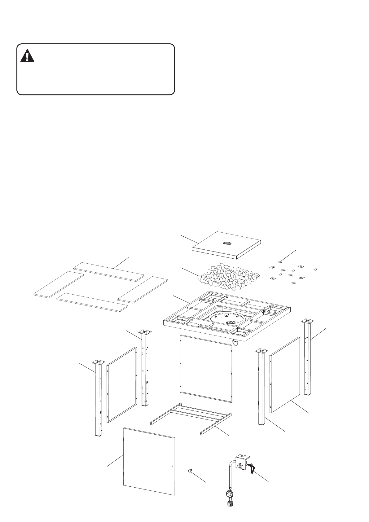
GENERAL ASSEMBLY
EXPLODED VIEW
6
Connecting & Disconnecting to Gas Source
IMPORTANT: Before connecting and
disconnecting appliance to gas source, make
sure control knob is in ‘OFF’ position.
CAUTION: When the appliance is not in use,
the gas must be turned off at the cylinder.
Familiarise yourself with the general information and
safety guidelines located at the front of this manual.
Check:
1. The cylinder is lled. A sloshing sound will be heard
when shaken.
2. The control knob is in the ‘OFF’ position.
Connecting
1. Ensure cylinder valve is in its full off position.
2. Check for any damage to either the cylinder
connection or the hose. NEVER attempt to use
damaged equipment.
3. When connecting the hose to the cylinder tighten the
nut to a positive stop by hand.
4. Open cylinder valve fully. If a leak can be heard at
either end of the hose, turn cylinder off and tighten
joint. Wait 5 minutes before re-testing and use
a soapy water solution to check the joint. If bubbles
appear the connection will need to be re-tightened.
Refer to page 12 for more detailed instructions on
connecting the appliance to the cylinder.
Disconnecting
1. Ensure the burner control is in the ‘OFF’ position.
2. Ensure cylinder valve is in the full off position.
For storage and cylinder exchange, disconnect hose
at the cylinder only, DO NOT disconnect hose from
appliance.
EXPLODED DIAGRAM
8
13
12
14
1
7
4
2
11
5
9
10
3
4 5
Page 5
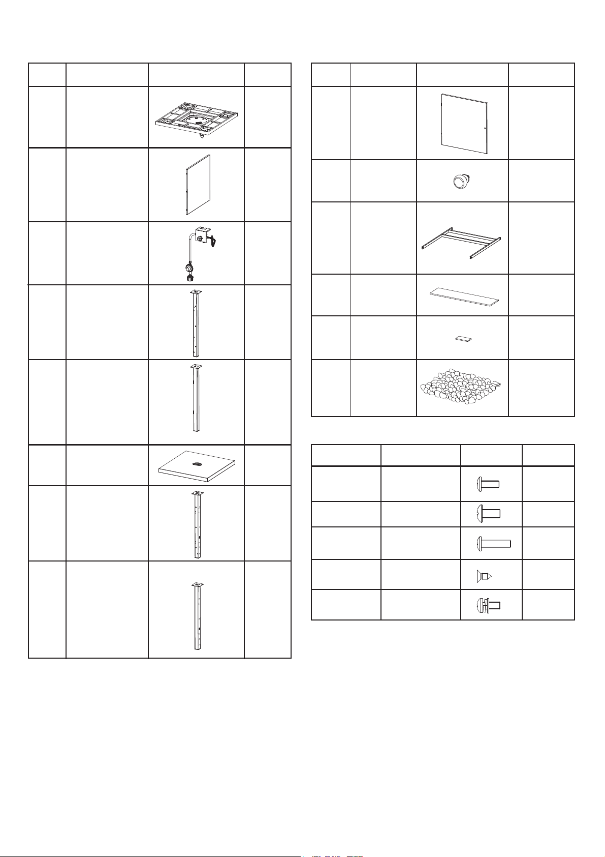
PARTS LIST
Part # Description Description
Table Top
1
Frame
2
Side Panel
3
Gas Valve Panel 1
Back Right Leg
4
Picture Qty
1
3
1
Part #
9
10
11
12
13
Door
Door Knob 1
Base Frame
Ceramic Tile
Cushion Pad 16
Picture Qty
1
1
4
Front Right Leg
5
6
Lid
7
Back Left Leg
8
Front Left Leg
14
Lava Rock 1
1
Hardware#
Picture QtyDimensions
1
A
B
M6 x 12
18M5 x 12
12
1
C
D
E
M5 x 20
ST4.2 x 9.5
M5 x 12
4
4
4
1
Page 6
ASSEMBLY INSTRUCTIONS
M5 x 12 Bolt M5 x 20 Bolt M6 x 12 Bolt ST4.2 x 9.5 Bolt
AA
CC DD EE
BB
ST4.2 x 9.5 Bolt
Your re table must be installed on a at, stable surface,
away from any combustible materials or construction.
Get a friend to help you put your gas re table together.
Lay cardboard down to protect gas re table nish and
assembly area.
Make sure the appliance control knob is turned “off”
before assembling.
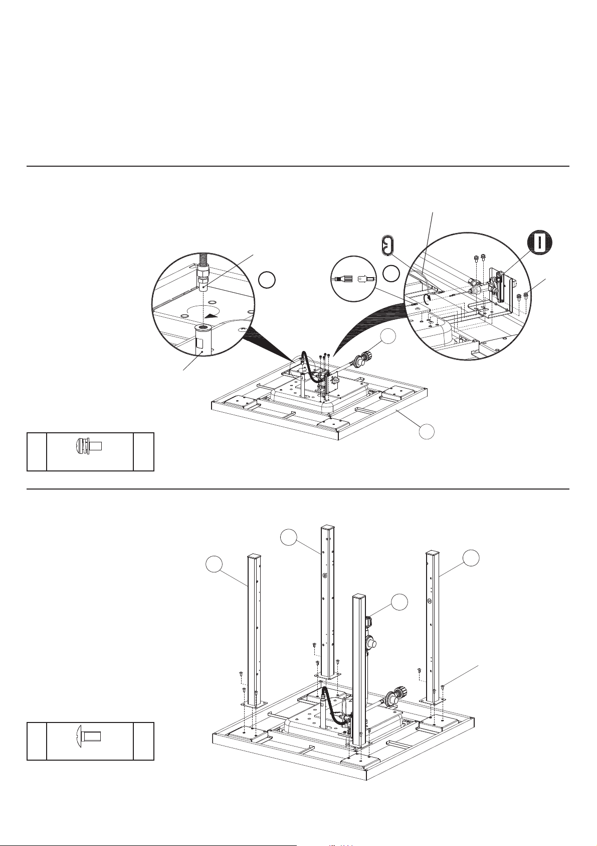
STEP 1
Place the table top frame
(1) upside down on to a
level surface, attach control
panel assembly (3) to the
table top frame (1) with 4
M5x12 bolts assembly (E).
Insert valve into the
injection pipe of burner as
illustrated (1.).
Insert the end of electrode
wire into valve as
illustrated (2.).
Adjust the distance
between the ignition pin
and ame orice to be
4-5mm in case of ignition
failure (If ignition failure
issue happened).
E
M5 x 12 Bolt Assembly
pcs
BURNER
4
GAS TIP
1.
Note: Remove any transit protection material.
Tools required:
• Philips head screwdriver (or cordless drill and bits).
• Crescent
APPROX ASSEMBLY TIME: 30-45 minutes
INSULATED TERMINAL
THERMOCOUPLE
ELECTRODE
WIRE
BLADE CONNECTOR
2.
E
3
1
STEP 2
Attach front right leg (5),
back right leg (4), front left
leg (8) and back left leg (7)
to the table top frame (1)
with 12 M6x12 bolts (B).
B
M6 x 12 Bolt
12
pcs
4
BR
7
BL
8
FL
5
FR
B
6 7
Page 7
ASSEMBLY INSTRUCTIONS
M5 x 20 Bolt M6 x 12 Bolt ST4.2 x 9.5 Bolt
CC DD EE
BB
M5 x 20 Bolt M6 x 12 Bolt ST4.2 x 9.5 Bolt
CC DD EE
BB
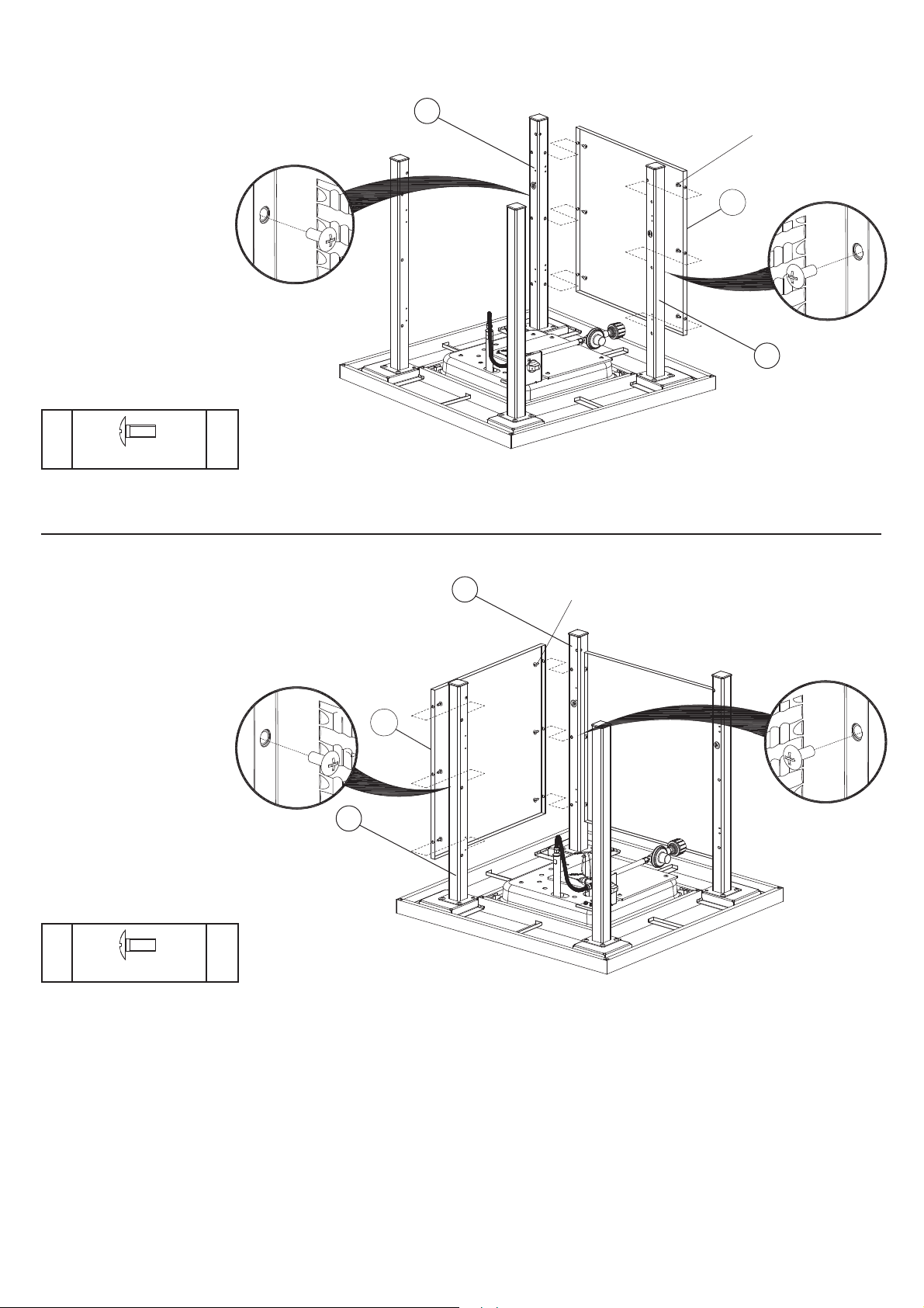
STEP 3
Attach one side panel (2) to
front left leg (8) and back left
leg (7) with 6 M5x12 bolts
(A).
7
BL
A
2
8
FL
A
M5 x 12 Bolt
6
pcs
STEP 4
Attach one side panel (2) to
back right leg (4) and back
left leg (7) with 6 M5x12
bolts (A).
4
BR
7
A
BL
2
A
M5 x 12 Bolt
6
pcs
Page 8
M5 x 20 Bolt M6 x 12 Bolt ST4.2 x 9.5 Bolt
CC DD EE
BB
ASSEMBLY INSTRUCTIONS
M6 x 12 Bolt ST4.2 x 9.5 Bolt
CC DD EE
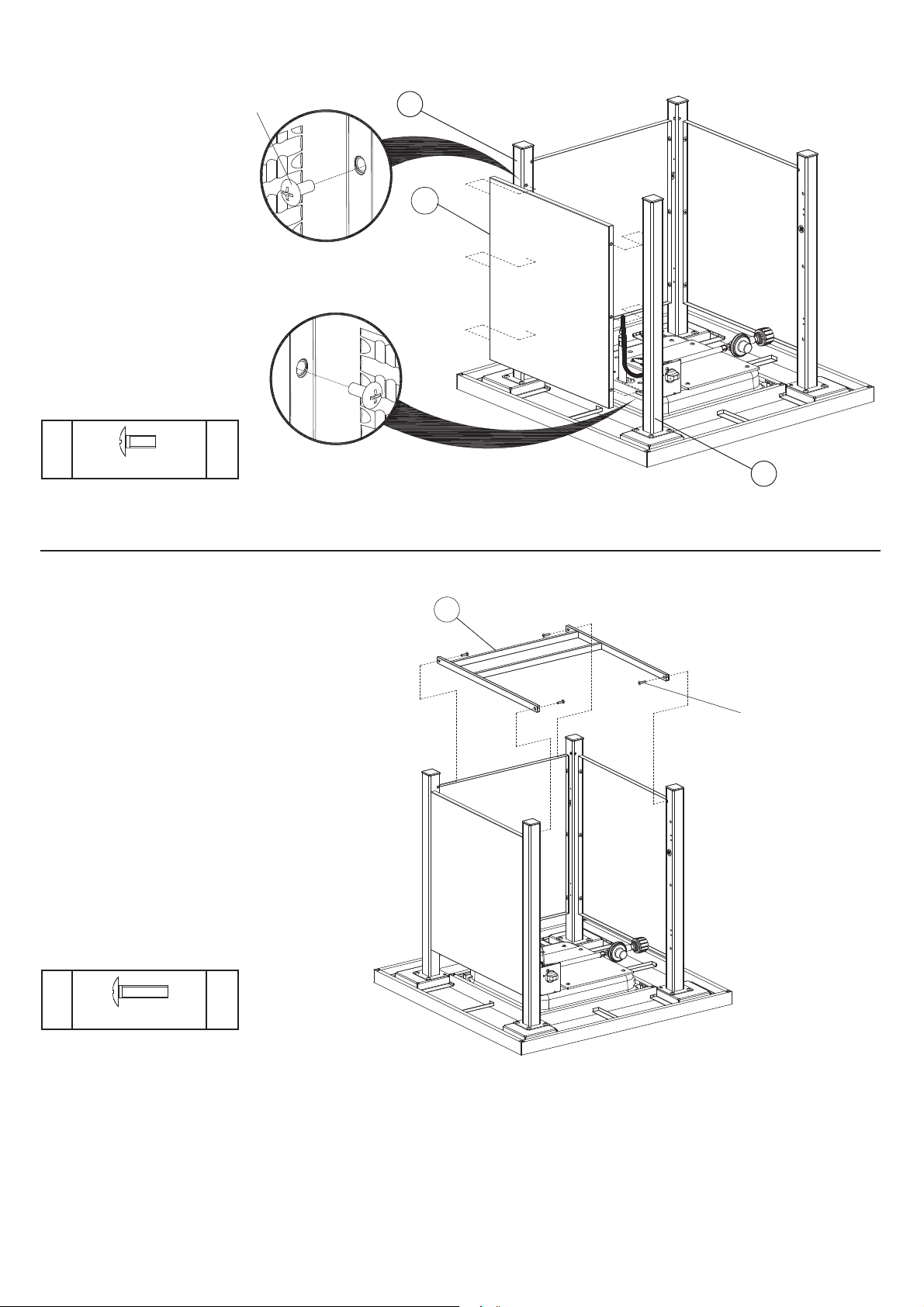
STEP 5
Attach one side panel (2) to
back right leg (4) and front
right leg (5) with 6 M5x12
bolts (A).
A
M5 x 12 Bolt
6
pcs
A
4
BR
2
5
FR
STEP 6
Attach base frame (11) to all
four legs with 4 M5x20 bolts
(C).
C
M5 x 20 Bolt
4
pcs
11
C
8 9
Page 9
ASSEMBLY INSTRUCTIONS
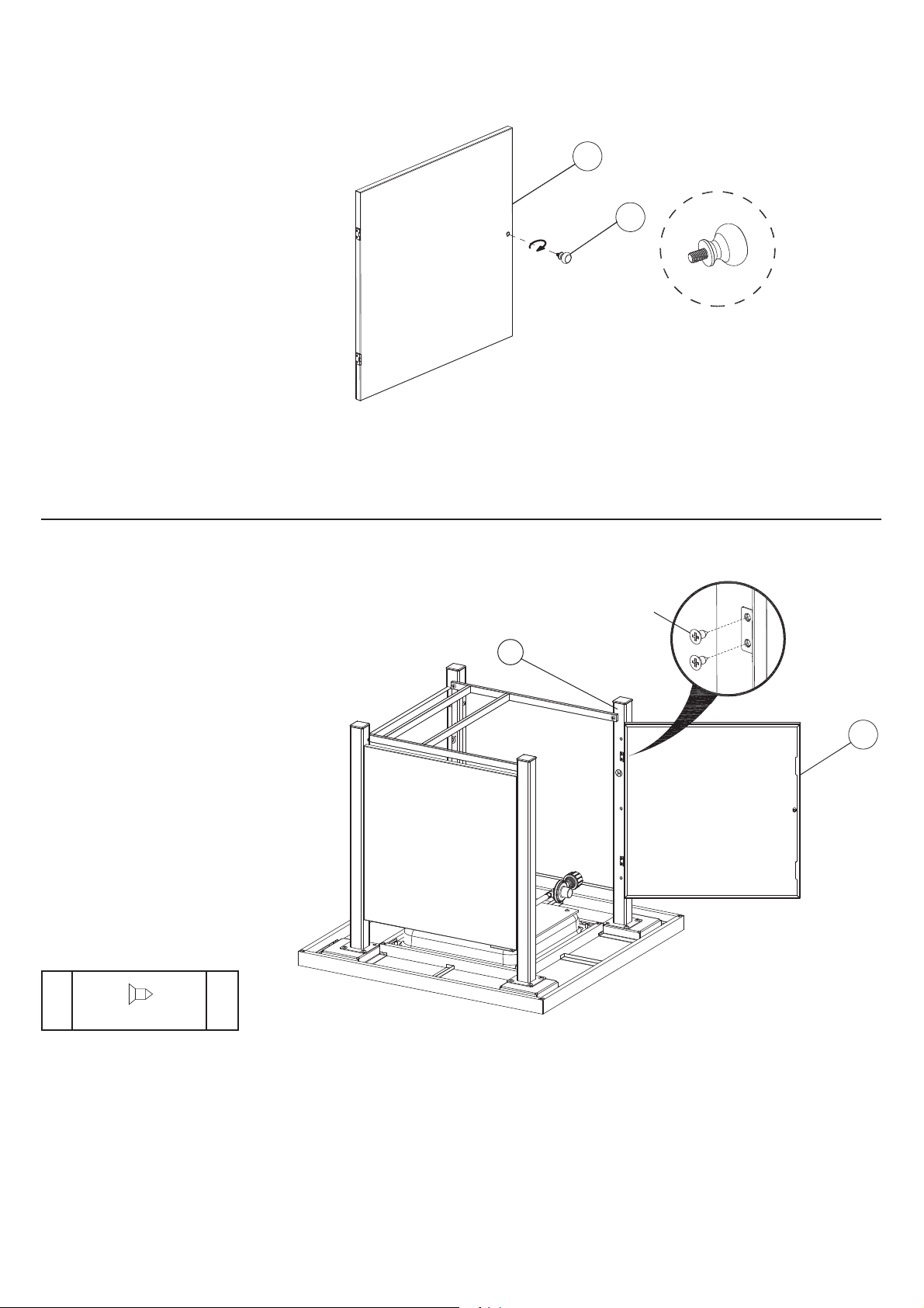
STEP 7
Screw door knob (10) to door
(9).
9
10
STEP 8
Attach door (9) to front left
leg (8) assembly with 4
ST4.2x9.5 bolts (D)
Note: With the help of a
friend, turn the gas re table
into upright position after this
step is nished.
D
ST4.2 x 9.5 Bolt
4
pcs
D
8
FL
9
Page 10
ASSEMBLY INSTRUCTIONS
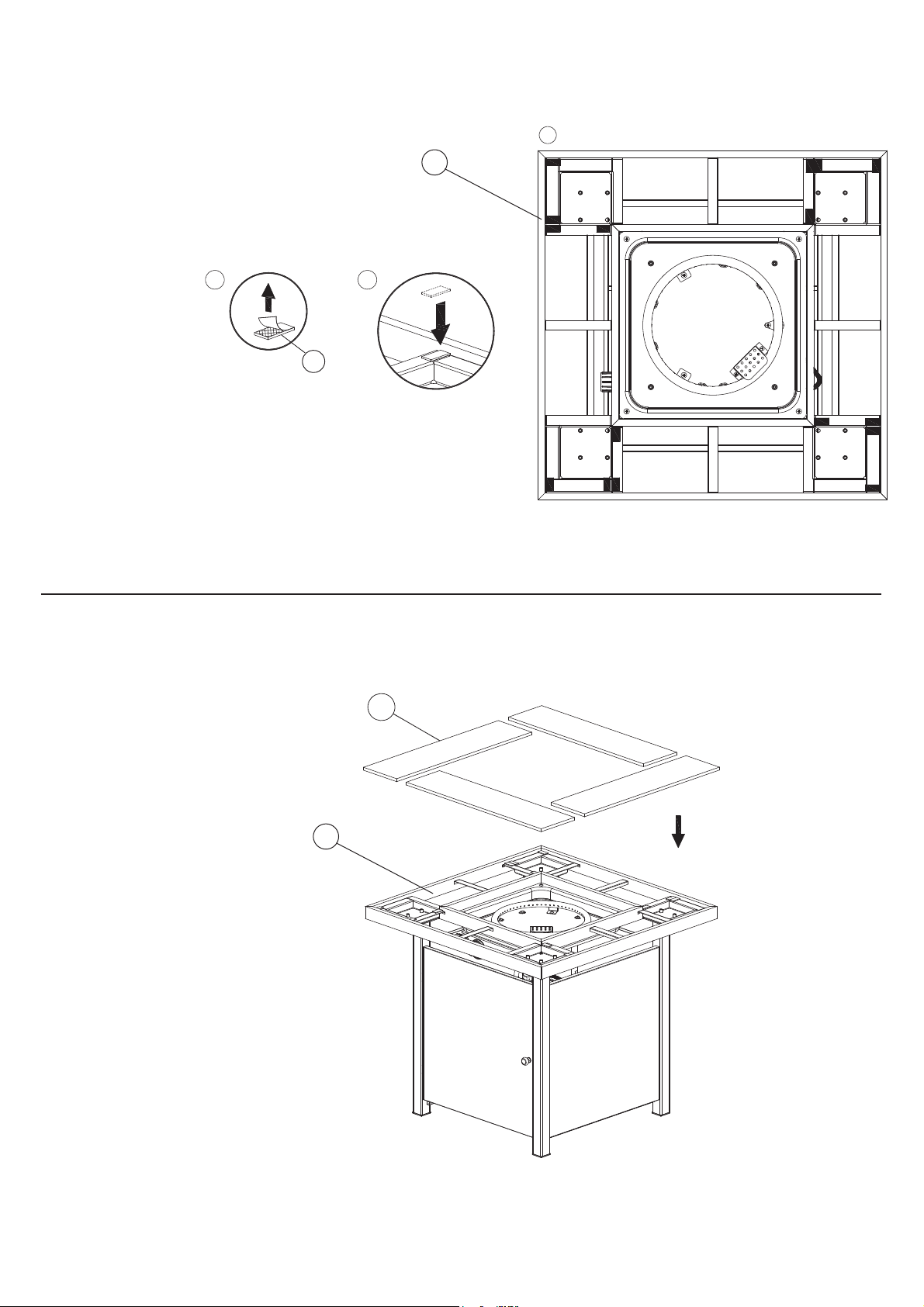
STEP 9
Peel and stick the 16
cushion pads (13) on
to the table top frame
(1).
Note: Before applying
the adhesive cushion
pads, be sure to
wipe down the metal
surface and make
sure it is free of any
dust or debris.
3
1
1
13
2
THE PLACEMENT OF CUSHION PADS
STEP 10
Put four ceramic tiles (12) on
table top frame (1).
12
1
10 11
Page 11
ASSEMBLY INSTRUCTIONS
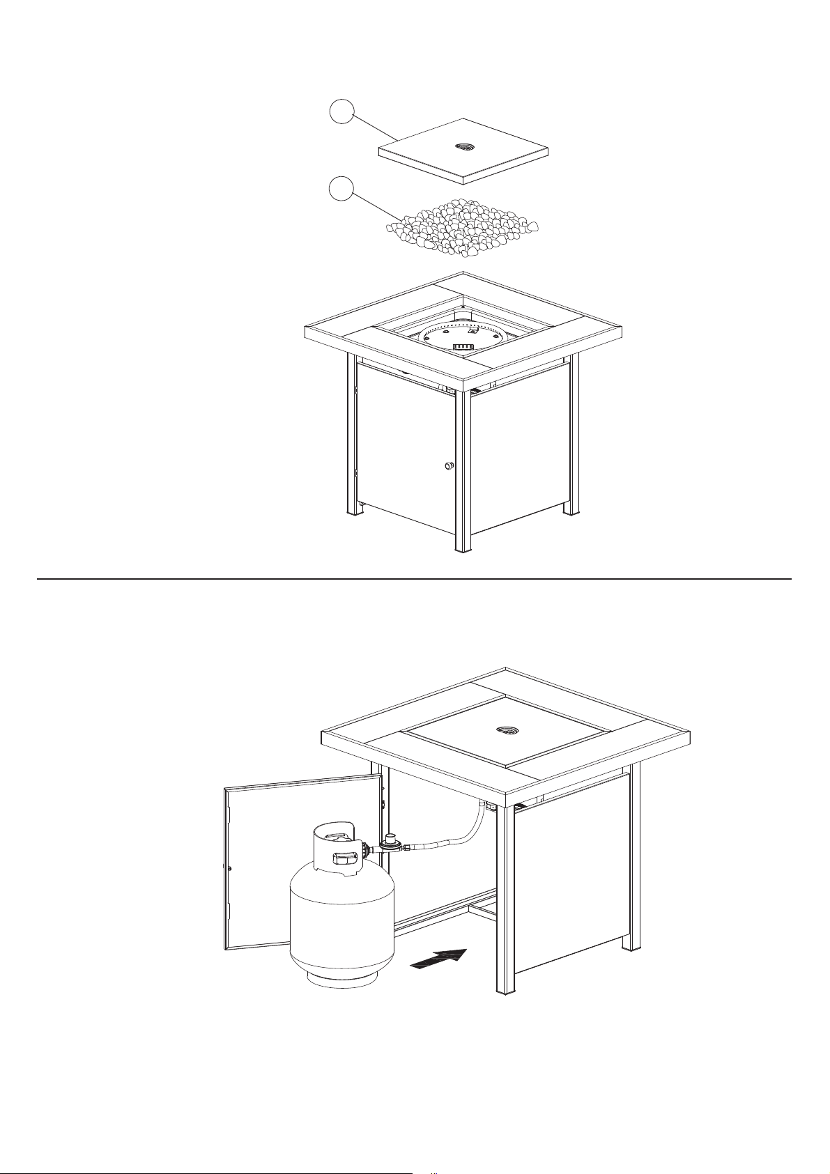
STEP 11
Put the lava rocks (14) into the
burning area, in the middle of
the table top.
Place the cover lid (6) onto the
table top when the gas re table
is not in use.
Note: To avoid ignition failure,
do not cover the ame orice
with lava rocks (see page 13).
6
14
STEP 12
Connect the gas cylinder (see next
page).
Page 12
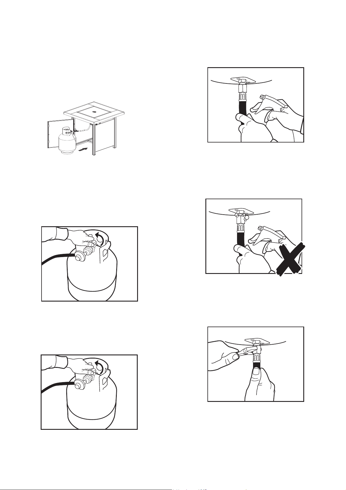
STEP 12
Turn on the gas cylinder ensuring that the control knob
on the outdoor heater is turned OFF at this point.
DO NOT ATTEMPT TO LIGHT THE HEATER!!.
STEP 12
Turn on the gas cylinder ensuring that the control knob
on the outdoor heater is turned OFF at this point.
DO NOT ATTEMPT TO LIGHT THE HEATER!!.
STEP 11
Ensure cylinder valve is in its full off position. Check
for any damage to either the cylinder connection or
the hose. NEVER attempt to use damaged equipment.
Attach the regulator and hose to your gas cylinder.
Tighten the nut to a positive stop by hand.
STEP 12
Turn on the gas cylinder ensuring that the control knob
on the outdoor heater is turned OFF at this point.
DO NOT ATTEMPT TO LIGHT THE HEATER!!.
STEP 13
Use a solution of soapy water (dishwashing liquid and
water is fine). Brush it on or use a spray bottle as
shown in the drawing. Ensure the connections have a
good coating.
STEP 14a
If the connection is leaking, bubbles will start to grow
in the soapy solution. If this happens shut off the gas
supply at the cylinder.
ASSEMBLY INSTRUCTIONS
STEP 12
Turn on the gas cylinder ensuring that the control knob
on the outdoor heater is turned OFF at this point.
DO NOT ATTEMPT TO LIGHT THE HEATER!!.
STEP 14a
If the connection is leaking, bubbles will start to grow
in the soapy solution. If this happens shut off the gas
supply at the cylinder.
STEP 11
Ensure cylinder valve is in its full off position. Check
for any damage to either the cylinder connection or
the hose. NEVER attempt to use damaged equipment.
Attach the regulator and hose to your gas cylinder.
Tighten the nut to a positive stop by hand.
STEP 12
Turn on the gas cylinder ensuring that the control knob
on the outdoor heater is turned OFF at this point.
DO NOT ATTEMPT TO LIGHT THE HEATER!!.
STEP 13
Use a solution of soapy water (dishwashing liquid and
water is fine). Brush it on or use a spray bottle as
shown in the drawing. Ensure the connections have a
good coating.
STEP 14a
If the connection is leaking, bubbles will start to grow
in the soapy solution. If this happens shut off the gas
supply at the cylinder.
STEP 14b
Tighten the connections using a crescent then repeat
steps 12-13.
STEP 14c
The connection is gas tight when no bubbles grow
around the gas connection.
ASSEMBLY INSTRUCTIONS
GAS CONNECTION INSTRUCTIONS
Step 1
Inside of the LPG compartment the gas hose and
regulator assembly are already connected to the gas inlet
of the appliance.
Place LPG cylinder in the LPG compartment.
Make sure the LPG cylinder base sits inside the metal
stand easily and completely.
Step 2
Ensure cylinder valve is in its full off position. Check for
any damage to either the cylinder connection or the hose.
NEVER attempt to use damaged equipment. Attach the
regulator and hose to your gas cylinder. Tighten the nut to
a positive stop by hand.
Step 4
Use a solution of soapy water (dishwashing liquid and water
is ne). Brush it on or use a spray bottle as shown in the
drawing. Ensure the connections have a good coating.
Step 5a
If the connection is leaking, bubbles will start to grow in
the soapy solution. If this happens shut off the gas supply
at the cylinder.
Step 3
Turn on the gas cylinder ensuring that the control knob
on the outdoor heater is turned OFF at this point.
DO NOT ATTEMPT TO LIGHT THE HEATER!!.
Step 5b:
Tighten the connections using a crescent then repeat
steps 3-4.
12 13
Page 13
GAS CONNECTION INSTRUCTIONS
STEP 12
Turn on the gas cylinder ensuring that the control knob
on the outdoor heater is turned OFF at this point.
DO NOT ATTEMPT TO LIGHT THE HEATER!!.
STEP 14a
If the connection is leaking, bubbles will start to grow
in the soapy solution. If this happens shut off the gas
supply at the cylinder.
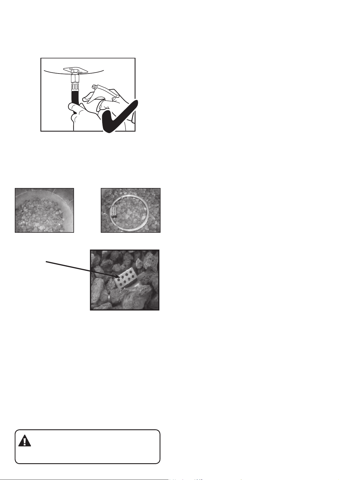
STEP 14c
The connection is gas tight when no bubbles grow
around the gas connection.
Step 5c:
The connection is gas tight when no bubbles grow around
the gas connection.
Step 6
Place all lava rocks evenly in the re table on the top
of the appliance. Never cover the ignition screen when
placing the lava rocks into the re table. Always keep
ignition screen visible.
Correct Incorrect
Screen
DO NOT place
Lava Rocks on
the screen. Keep
screen clear.
WARNING:
This screen must be clear and free of
obstructions at all times to ensure proper
operation.
Page 14
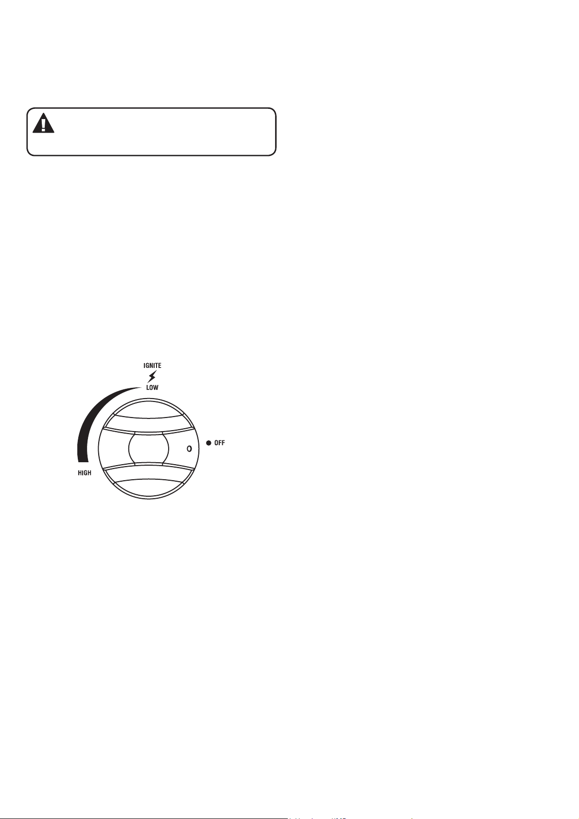
TEST FIRING APPLIANCE
Test re appliance, following the lighting instructions
found on the appliance. Leak test all gas connections with
soapy water. Soap bubbles indicate gas leakage.
DO NOT use a ame to test for gas leaks.
WARNING: White smoke may appear around
the burner during the rst minute of the initial
ring.
LIGHTING INSTRUCTIONS
1. Make sure the control knob is in the ‘OFF’ position.
2. With cylinder valve in ‘OFF’ position turn the control
knob anti-clockwise to ‘IGNITE’ (you will hear a single
click sound). Check for sparking to the burner.
3. If spark is not evident at the burner ignition point,
check that the ignition lead is rmly attached to the
control and sparker tip.
4. With sparking established turn the cylinder valve ‘ON’.
5. Push down and turn the control knob anti-clockwise
to ‘IGNITE’ again. This will light the burner. Observe if
the burner has lit. If not, repeat this process.
STORAGE & MAINTENANCE
To obtain the best performance from your re table, you
must perform the following storage and maintenance
activities on a regular basis:
• Allow at least 30 minutes for the re table to cool down
after use, then disconnect and remove the cylinder.
• Store the gas cylinder in a dry, well ventilated and
sheltered area away from weather and dust, out of
the reach of children, and not in a building, garage or
any other enclosed area.
• Storage indoors is permissible only if the cylinder is
disconnected and removed. It is recommended that
the re table be stored indoors during the winter if it
will be subjected to freezing temperatures.
• Keep the re table area clear and free from
combustible materials, gasoline and other ammable
vapors and liquids.
• If the re table is not in use, it must be covered to
protect from weather or other adverse elements.
• Never use a vacuum cleaner on the lava rocks.
• Installation and repair should be done by a qualied
service person.
6. If the burner fails to ignite after several attempts turn
off gas supply at cylinder valve and the control knob
off (clockwise). Wait ve minutes before attempting to
relight with ignition sequence.
7. Adjust the heat by turning the control knob to the
‘HIGH’/’LOW’ position.
8. To turn off, turn the cylinder valve to the ‘OFF’
position and then turn the control knob to ‘OFF’.
Note: If for some reason, ignitor fails to produce a spark
at the electrode, re table can be lit by a long match.
Move lava rocks to gain access to the burner (DO NOT
touch unless completely cool). Wearing heat resistant
gloves, position long lit match close to burner port.
DO NOT lean over burner while lighting.
Push and turn burner control knob to “LOW” position. The
burner should light within 5 seconds.
• The re table should be inspected at least annually by
a qualied service person. It is imperative that
control compartment, burners and circulating air
passageways of the re tablet be kept clean.
14 15
Page 15
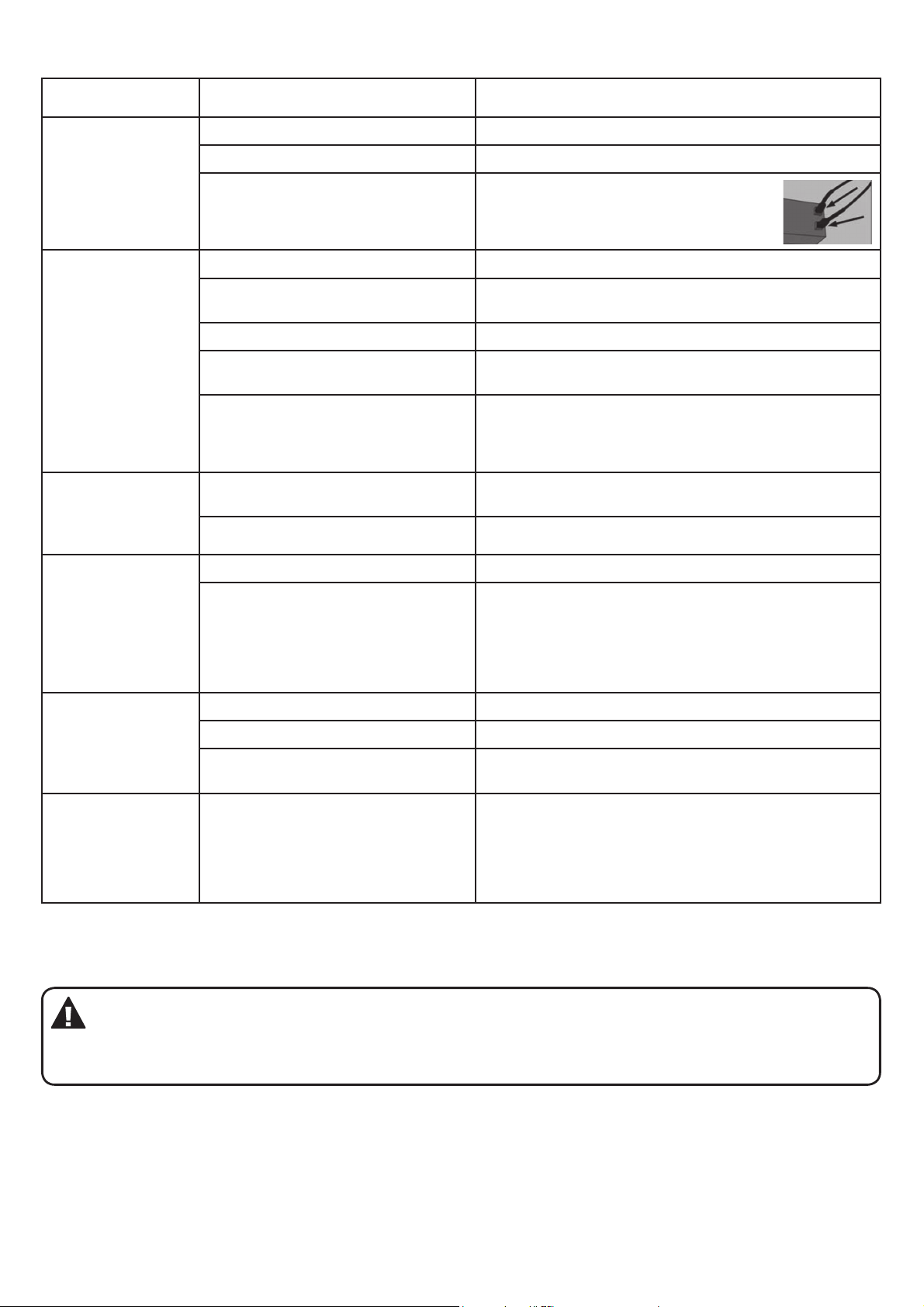
TROUBLE SHOOTING
Problem: Condition: Solution suggested:
Igniter pin and burner are wet. Wipe dry with a cloth.
Igniter pin cracked or broken. Contact retailer where purchased for replacement part.
Appliance won’t
light
Electrode wire is loose or
disconnected.
No gas ow. Check if gas cylinder is empty. If yes, replace.
Reconnect wire to the igniter box
located inside the table base behind
the igniter button.
Burner will not
light using a
match
Appliance emits a
lot of black smoke
when lit
Sudden drop in
gas ow
Flame blow out
Regulator is not fully connected to
the tank.
Gas ow is obstructed. Check hose for bends or kinks.
Spider webs or insect nest in the
venturi (end of burner tube).
Burner ports are clogged.
Flame is obstructed at burner ports.
Regulator hose is pinched. Check the regulator hose for bends or kinks.
No gas ow. Check if gas cylinder is empty. If yes, replace.
Excess ow safety valve has been
activated.
High or gusting winds. Increase ame to “High”.
No gas ow. Check if gas cylinder is empty. If yes, replace.
Excess ow safety valve has been
activated.
Check gas cylinder connection.
Clean the venturi.
Insert an opened paper clip into each of the burner
ports to clean them. Ensure the appliance is off and all
parts are cooled before attempting to clean the burner
ports.
Make sure all the gas burner ports are free of any lava
rocks or debris to allow the gas to ow freely.
Turn the control knob to “OFF”, Close the gas cylinder
valve and disconnect the regulator from the cylinder.
Turn the control knob to “HIGH”. Wait 1 minute. Turn
the control knob to “OFF”. Reconnect regulator to gas
cylinder. Open cylinder valve slowly. Light appliance as
indicated in “To Light” section.
See “Sudden drop in gas ow” above.
Irregular ame
pattern or ame
does not come
out of the entire
length of the
burner
Note: If the appliance cannot be adjusted to perform correctly it should not be used until serviced or repaired.
Warning: Improper installation, adjustment, alteration, service or maintenance can cause injury or property
damage. Any modications or adjustments made to product without prior authority from the manufacturer
will void any warranty claims. Read the installation, operating and maintenance instructions thoroughly before
installing or servicing this equipment.
Burner ports are clogged. See “Burner will not light using a match” above.
Page 16
Limited Warranty
OUTDOOR HEATER RANGE
Aber Living warrants the purchaser of this product against defects in workmanship and material,
for a period of up to 12 months f rom the date of purchase. The warranty is non-transferable and
becomes void if used for commercial or rental purposes.
Warranty and purchase receipt of this product are to be retained as proof of purchase and must be
presented if making a claim under the terms of the Aber Living Warranty. Repairs under warranty
are free of charge, provided the product is delivered to our Service Department or Authorised
Service Agent and freight charges both ways are paid by the owner. No liability will be accepted for
any loss of damage in transit.
Note: In most cases the Burner Head, Hose and Regulator only will need to be returned.
Aber Living reserves the rights to replace or repair the product within the warranty period.
Warranty does not apply to any defect, deterioration (including corrosion if located within 1km of
the sea), loss, injury or damage occasioned by or as a result of the misuse or abuse, negligent
handling or if the product has not been installed and used in accordance with the instructions. The
warranty is void if there is evidence of the product being tampered with by unauthorised persons.
If the product includes one or a number of accessories, only the defective accessory or part will be
replaced, eg. hose, regulator, piezo igniter or reflector.
In the event of Aber Living choosing to replace the product, the warranty will expire at the original
date, i.e. 12 months from the original purchase date.
Where this product contains information f rom an overseas country, nothing in that
information is intended to limit any condition, guarantee, right or remedy which may be
available under the Consumer Guarantees Act 1993, except to the extent permitted by that Act.
Approved for Outdoor Use Only
For service, spare parts or product information in New Zealand, please call Aber Living
on the Customer Service Line - 0800 161 161. www.aberliving.co.nz
YOUR PURCHASE RECORD (please complete)
Date of Puchase
Model Number
Serial Number (if applicable)
Purchased from
Attach copy of purchase receipt here
16 PB
20
 Loading...