

Page 1
At Space-Ray, industrial comfort heating is a challenge we take seriously. We have
been manufacturing gas-fired infrared heating systems since 1958. The quality and
performance of our heaters are based on over 45 years of field experience and exposure to a wide variety of industrial heating problems. Our reputation is built upon a
solid track record for providing radiant ef ficient, easy-to-install, and high quality infrared
heating equipment.
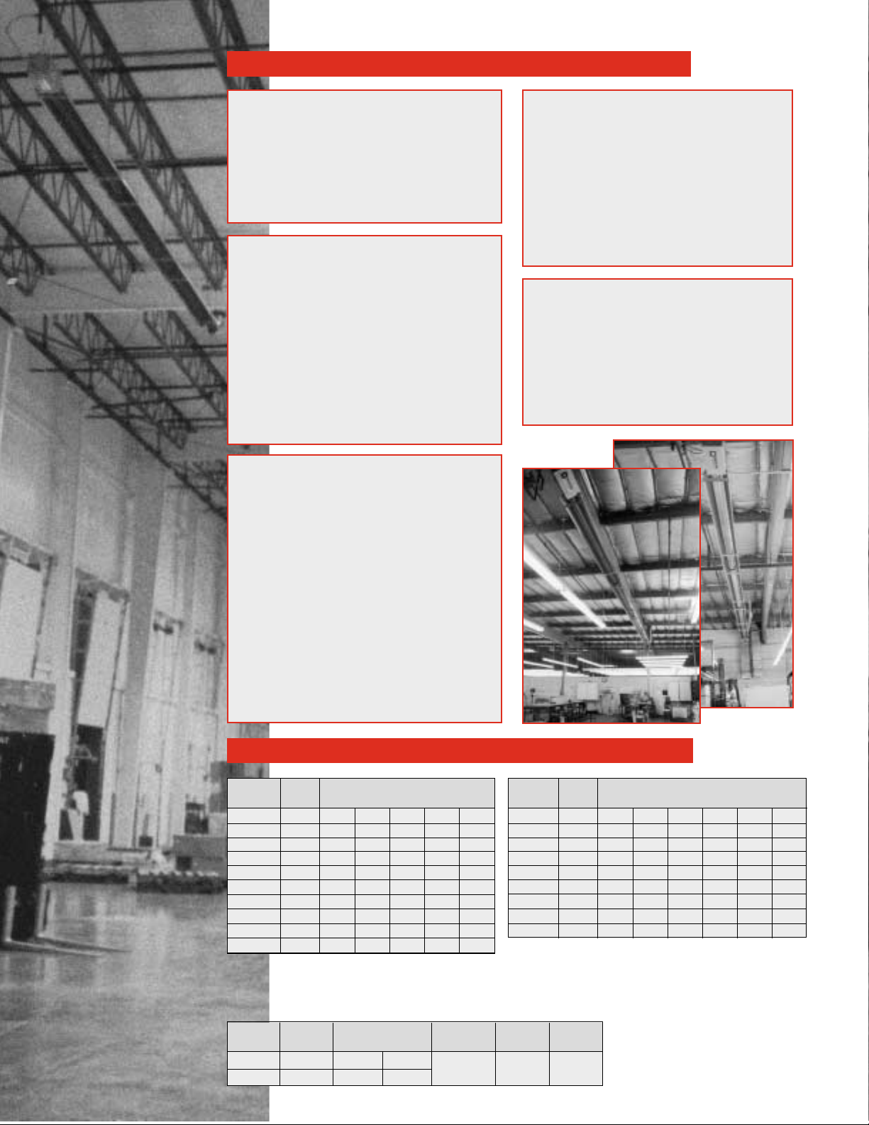
Space-Ray infrared tube heaters are ideal for complete building heat or even spot
heating needs. The best applications include: manufacturing plants, warehouses,
auto dealerships, aircraft hangars, loading docks, weld shops, truck or auto service
areas, car washes, fire stations, greenhouses, gymnasiums, garages, machine
shops, tennis courts, swimming pools, maintenance shops, farm buildings and many
many more.
Space-Ray infrared heaters heat like the sun by transferring radiant heat energy directly to the areas to be heated. Radiant energy is absorbed by concrete floors, objects and
people, and re-radiated to warm the surrounding area. This principle is similar to the
sun’s radiant heat energy heating Earth but not the upper atmosphere. This heating
technology creates a comfort zone at floor level, not at the ceiling, and is much more
efficient than conventional forced air heating systems.
A highly radiant efficient Space-Ray infrared heating system can normally save a
building owner 30% to 50% in annual fuel costs when compared to forced air heating
systems. In fact, some Space-Ray customers report fuel savings as high as 70% with
a payback of less than one year. With a Space-Ray system, your investment payback
accrues not only from reduced energy costs, but from reduced maintenance costs,
too. So when you think industrial heating, think Space-Ray. Call us at 1-800-438-4936
for the name of our representative nearest you.
Infrared Gas Heaters For Industry Since 1958
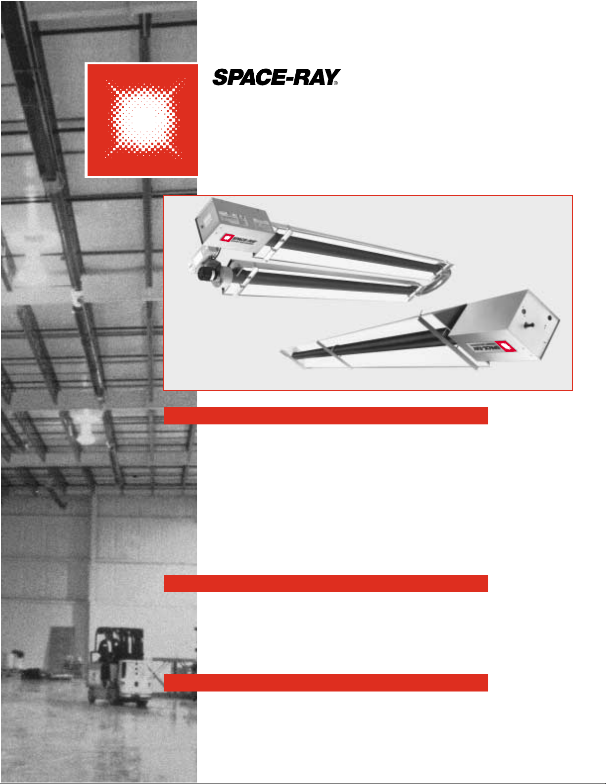
LOW INTENSITY
ETS/ETU Series Tube Heaters
SPACE-RAY®…A TRUSTED NAME IN INFRARED HEATING
HEATING TECHNOLOGY FOR THE NEXT MILLENNIUM
30%-50% FUEL SAVINGS
SPECIFICATIONS
ETU Series
ETS Series
Page 2
MODEL
BTU/HR
INPUT
MODEL
ETS/U 130 130,000 X X X
ETS/U 140 140,000 X X
ETS/U 150 150,000 X X
ETS/U 160 160,000 X X
ETS/U 175 175,000 X X
ETS/U 180 180,000 X X X X
ETS/U 200 200,000 X X X X
ETS/U 225 225,000 X X X X
ETS/U 250 250,000 X X X X
ETS/U 40 40,000 X X
ETS/U 50 50,000 X X X
ETS/U 60 60,000 X X
ETS/U 75 75,000 X X
ETS/U 80 80,000 X X
ETS/U 90 90,000 X X
ETS/U 100 100,000 X X
ETS/U 110 110,000 X X
ETS/U 120 120,000 X X
ETS/U 125 125,000 X X X
MODEL SELECTIONS
GENERAL FEATURES
• 19 different Btu/hr sizes and more than 100
different configurations to custom design
your infrared heating system.
• CSA design certified
• Vented or indirect vented operation
• Sidewall or through-the-roof venting
• Natural and propane gas models
PULL THROUGH SYSTEM
• Products of combustion are pulled
through the combustion chamber for
increased radiant efficiency and greater
safety
• No draft hoods, totally enclosed
combustion chamber
• Heavy-duty draft inducer with permanently
lubricated, totally enclosed, fan cooled,
and heavy-duty ball bearing motor for
maintenance-free operation
• Draft inducer can be rotated 45° or 90°
for sidewall venting
BURNER SYSTEM
• Heavy-duty cast iron burner
• 10-year limited warranty on burner
• Inside or outside air for combustion
• Up to 50 ft. outside combustion air duct
capability
• Standard 6” combustion air duct opening
• Reliable direct spark ignition system and
100% gas shut-off safety control
• 30-second pre-purge prior to ignition
• State-of-the-art step opening redundant
combination gas valve for quiet ignition
and added safety
• Diaphragm air switch for proof of venting
before gas flow and ignition
• Diagnostic monitoring light system
• Burner inspection sight glass
RADIANT EMITTER TUBE SYSTEM
• 4” O.D. heavy-duty calorized aluminized
steel or alumi-therm steel combustion
chamber (10 feet) and heavy duty hotrolled steel emitter tubes
• 3-year limited warranty on the emitter
tubes
• Suitable for horizontal or angle mounting
up to 45°
• Optional 90° elbows
• Up to 75 feet sidewall vent capacity
REFLECTOR SYSTEM
• Highly efficient aluminum reflectors with
reflectivity rating of 97.5%
• Optional end, corner, side and U-bend
reflectors
• Optional decorative grille
• Individual reflectors can be rotated up to
45° to direct heat where needed
• Easy-to-use mounting brackets
TOTAL EMITTER LUBE LENGTH*
15 FT** 20 FT 30 FT 40 FT 50 FT
ETS/ETU SERIES FEATURES
TOTAL EMITTER LUBE LENGTH*
30 FT 40 FT 50 FT 60 FT 70 FT 80 FT
NOTE: For all installations higher than
2000 ft. above sea level, please consult
the factory regarding recommended
derating of heaters.
GAS
TYPE
NATURAL 3.5” W.C. 5” W.C* 14” W.C.
PROPANE 10” W.C. 11” W.C.** 14” W.C.
BURNER
PRESSURE
VOLTAGE
AMPS
IGNITION
TYPE
MIN MAX
120 VAC
60 HZ
2.6
DIRECT
SPARK
*Indicate model number based on Btu/hr input (e.g., 100,000 Btu/hr), total emitter length, (e.g., 40 feet) and gas type (e.g., natural gas). The
unit selection for a straight tube would be ETS100-40-N and for a U-tube would be ETU100-40-N. **Available only on ETS models.
*7” W.C. for ETS/ETU (180-250) **12” W.C. for ETS/ETU (180-250)
SUPPLY PRESSURE
BTU/HR
INPUT
Page 3

MODEL
ETS AND ETU
DRAFT INDUCER CONTROL BOX
Flue Connection: 4” Round for ETS/U (40-75)
6” Round for ETS/U (80-250)
Fresh Air Connection: 4” Round for ETS/U (40-75)
6” Round for ETS/U (80-250)
ETS OPTIONS
90° ELBOW CORNER REFLECTOR
ETS - BOTTOM VIEW ETS - END VIEW
DIMENSIONS
MINIMUM RECOMMENDED MOUNTING HEIGHTS
MINIMUM CLEARANCES TO COMBUSTIBLES
ETU - BOTTOM VIEW ETU - END VIEW
TOTAL TUBE OVERALL
LENGTH (FT) DIMENSION”L”(FT)
D
E
S
I
G
N
C
E
R
T
I
F
I
E
D
TOTAL TUBE OVERALL
LENGTH (FT) DIMENSION ”L” (FT) MODEL
ETS (40, 50)
ETS (40, 50, 60, 75)
ETS (40, 50, 60, 75, 80, 90,
100, 110, 120, 130)
ETS (80, 90, 100, 110, 120,
125, 130, 140, 150, 160,175)
ETS (125, 130, 140, 150,
160, 175, 180, 200, 225, 250)
ETS (180, 200, 225, 250)
ETS (180, 200, 225, 250)
ETS (180, 200, 225, 250)
15’
20’
30’
40’
50’
60’
70’
80’
17’3”
22’3”
32’3”
42’3”
52’3”
62’3”
72’3”
82’3”
ETU (40, 50, 60, 75)
ETU (50, 60, 75, 80, 90,
100, 110, 120, 130)
ETU (80, 90, 100, 110, 120,
125,130, 140, 150, 160, 175)
ETU (125, 130, 140, 150,
160,175,180,200, 225, 250)
ETU (180, 200, 225, 250)
ETU (180, 200, 225, 250)
ETU (180, 200, 225, 250)
MODEL
MODEL
ETS/U 40
ETS/U 50
ETS/U 60
ETS/U 75
ETS/U 80 & 90
ETS/U 100 & 110
10 feet
11 feet
12 feet
13 feet
13 feet
14 feet
9 feet
10 feet
11 feet
12 feet
12 feet
13 feet
ETS/U 120 & 125
ETS/U 130 & 140
ETS/U 150
ETS/U 160 & 175
ETS/U 180 & 200
ETS/U 225 & 250
14 feet
15 feet
15 feet
16 feet
18 feet
20 feet
13 feet
14 feet
14 feet
15 feet
17 feet
19 feet
HEIGHT AT
HORIZONTAL
HEIGHT AT
45° ANGLE
ETS/U (40, 50)
ETS/U (60, 75)
ETS/U (80, 90)
ETS/U 100
ETS/U (110, 120, 125, 130)
ETS/U (140, 150, 160, 175)
ETS/U (180, 200, 225, 250)
MINIMUM CLEARANCES TO COMBUSTIBLES MODEL NO.
SIDE
CEILING BELOW END
(45°)
FRONT
(45°)
REAR
HORIZONTAL
27”
27”
52”
66”
66”
84”
86”
6”
6”
6”
6”
6”
6”
18”
40”
60”
84”
88”
101”
106”
132”**
30”
30”
30”
40”
40”
48”
48”
48”
48”
52”
66”
66”
84”
84”
12”
12”
12”
20”
20”
24”
24”
*When used indirect vented, clearances to ceiling from top of exhaust hood must be 12” on ETS/U (40-75), and 18” on
ETS/U (80-250). If optional corner or U-bend reflectors are not used, clearance must be 18”. **Clearance below the heater
is 132” for the first 20 ft. of the emitter tube and reduces to 72” 20 ft. downstream from the control box.
Note: Consult factory if reduced clearances are required.
This chart is intended as a guide only, as heaters may be mounted at various heights and angles. Since straight tube heaters are always hotter at the burner end than
at the exhaust end, always observe the minimum recommended mounting heights shown above. Use ETU series for spot heating. Please consult your local SpaceRay Representative for a detailed analysis of your particular infrared heating requirements.
20’
30’
40’
50’
60’
70’
80’
12’9”
17’9”
22’9”
27’9”
32’9”
37’9”
42’9”
L
L
18”
18”
9”
13”
6”
15”
Control
Box
Draft
Inducer
18”
31”
6”
45° ANGLE
(MAXIMUM)
HEIGHT AT
HORIZONTAL
HEIGHT AT
45° ANGLE
1/2
Page 4

COMBUSTION AIR AND VENTILATION
Combustion air and venting requirements for all gas-fired heating equipment must be provided per the National Fuel Gas Code NFPA54 or the authority having jurisdiction over the
installation. In contaminated atmospheres or high humidity areas, optional outside air for combustion can be supplied. Heaters can be common vented, direct vented, or indirect
vented. Refer to the Installation and Operation Instructions for further information. A vented installation must be vented to the outside of the building with a flue pipe. An Indirect
vented installation requires a minimum ventilation flow of 4 CFM per 1000 Btu/hr of total installed heater capacity on natural gas by either gravity or power ventilation (4.18 CFM per
1000 Btu/hr on propane). For indirect vented applications, building exhaust openings must be located above the level of the heaters and inlet air openings must be located below
the level of the heaters.
FOR YOUR SAFETY
OPERATE SPACE-RAY GAS INFRARED HEATERS WITH PROPER CARE AND OBSERVE ALL SAFETY PRECAUTIONS. Installation and service must be performed by a licensed contractor. The installation must conform to local codes. In the absence of local codes, the installation must conform to the National Fuel Gas Code ANSI Z223.1 (latest edition, also known
as NPFA54) or CAN / CSA-B149 installation codes (latest edition). These codes are available from the National Fire Protection Association, Inc., Batterymarch Park, Quincy, MA 02269
or the Canadian Gas Association, 55 Scarsdale Road, Toronto, Ontario MB3 2R3 Canada.
A Division of Gas-Fired Products, Inc.
P.O. Box 36485 Charlotte, NC 28236 Telephone (Toll Free) 1-800-438-4936 (704) 372-3485 Fax (704) 332-5843
Copyright 2003, GFP INC. 10325M FORM#S45504
ETS/ETU SERIES LAYOUTS
The ETS/ETU series, with more than 100 different configurations, offers optimum flexibility in custom designing an
infrared heating system. The ETS series is available in multiple configurations (straight, L, Z, and expanded U-shape) with
lengths from 15’ to 80’ long. For added versitality , 90°elbows, corner reflectors, and side reflectors are available for close
area mounting near walls, doors, and corners. The ETU series is available in seven different configurations and provides
more uniform radiant heat energy distribution. The ETU series is ideal for high heat loss areas and spot heating.
ETS/ETU SERIES LAYOUTS
Only 15 ft. to 50 ft. systems are shown. Please refer to the Installation and Operation Instructions for complete layouts.
www.spaceray.com • email: info@spaceray.com
LEGEND
CONTROL UNIT DRAFT INDUCER 10FT. BODYSECTION 5 FT. BODY SECTION 90° ELBOW 180° U BEND
ETS SERIES
STRAIGHT L-SHAPE
EXPANDED
Z-SHAPE STRAIGHT L-SHAPE
EXPANDED
Z-SHAPE
U-SHAPE U-SHAPE
15 FT SYSTEM
40 FT SYSTEM
20 FT SYSTEM
25 FT SYSTEM
45 FT SYSTEM
30 FT SYSTEM
35 FT SYSTEM 50 FT SYSTEM
ETU SERIES
20 FT SYSTEM 30 FT SYSTEM 40 FT SYSTEM 50 FT SYSTEM
 Loading...