

Page 1
INSTALLATION AND OPERATION INSTRUCTIONS
OWNER / INSTALLER: For your safety this manual must be carefully and thoroughly read
and understood before installing, operating or servicing this heater.
INFRARED RADIANT TUBE HEATER
Two Stage Push Through System (Positive Pressure)
Models
:
PTS SERIES: (40, 50, 75, 100, 125, 150, 175, 200) – N7/L7
PTU SERIES: (40, 50, 75, 100, 125, 150, 175, 200) – N7/L7
!INSTALLER: This manual is the property of the owner. Please present this manual to
the owner when you leave the job site.
WARNING: Improper installation, adjustment, alteration, service, or maintenance can
cause property damage, injury or death. Read the installation, operation and maintenance
instructions thoroughly before installing or servicing this equipment.
IF YOU SMELL GAS:
^ DO NOT try to light any appliance.
^ DO NOT touch any electrical switch; DO NOT use any
telephone in your building.
^ IMMEDIATELY call your gas supplier from a neighbor's
telephone. Follow the gas supplier's instructions. If you
cannot reach your gas supplier, call the fire department.
!IMPORTANT
Post Office Box 36485 (28236) 305 Doggett Street (28203) Charlotte, North Carolina
Phone (704) 372-3485 Fax (704) 332-5843 www.spaceray.com email: info@spaceray.com
Form #43343530
July 08
FOR YOUR SAFETY
: SAVE THIS MANUAL FOR FUTURE REFERENCE.
SPACE-RAY
DO NOT store or use gasoline or other
flammable vapors and liquids in the
vicinity of this or any other appliance.
Page 2

TABLE OF CONTENTS
SECTION
DESCRIPTION PAGE
1.0) Safety........................................................................................................................................ 2
2.0) Installer Responsibility........................................................................................................... 2
3.0) General Information ............................................................................................................... 2
4.0) Minimum Clearances to Combustibles ............................................................................... 4
5.0) Specifications .......................................................................................................................... 5
6.0) Packing List ............................................................................................................................. 5
6.1) Accessory Packages ............................................................................................................... 9
7.0) Typical Layouts – PTS/U Series ........................................................................................... 11
7.1) Typical Assembly Layout........................................................................................................ 12
8.0) Dimensions – PTS Series....................................................................................................... 13
8.1) Dimensions – PTU Series ..................................................................................................... 14
8.2) Heater Assembly / Joining of Tube Sections...................................................................... 15
9.0) Typical Suspension Methods................................................................................................. 17
10.0) Assembly of Tube Sections.................................................................................................... 18
10.1) Assembly of Extension Section............................................................................................. 19
10.2) Inserting Turbulators .............................................................................................................. 20
10.3) Adding Body Reflectors.......................................................................................................... 21
11.0) Adding Optional 90º Elbow (PTS Only) ............................................................................... 22
11.1) Adding Optional Corner Reflector (PTS Only) .................................................................... 22
11.2) Adding 180º U-Bend (PTU Only)........................................................................................... 23
11.3) Adding Optional U-Bend Reflector (PTU Only) ................................................................... 23
12.0) Attaching Control Box Assembly .......................................................................................... 24
12.1) Connecting The TISS System ............................................................................................... 25
13.0) Gas Connections And Regulations ....................................................................................... 28
14.0) Instructions For Pressure Test Gauge Connection............................................................. 30
15.0) Electrical Connections............................................................................................................ 31
16.0) Venting...................................................................................................................................... 34
17.0) Air For Combustion ................................................................................................................. 38
17.1) Direct Outside Air For Combustion....................................................................................... 38
18.0) Lighting and Shutdown Instructions .................................................................................... 40
19.0) Sequence of Operation .......................................................................................................... 40
20.0) Burner Component Location ................................................................................................. 41
21.0) Cleaning And Annual Maintenance...................................................................................... 42
22.0) Troubleshooting Guide ........................................................................................................... 43
23.0) Replacing Parts ....................................................................................................................... 46
23.1) Removal of Main Burner And Electrodes ............................................................................ 46
23.2) Removing Gas Valve And Manifold Assembly ................................................................... 47
23.3) Air Switch Pressure Check .................................................................................................... 47
23.4) Ignition System Checks.......................................................................................................... 48
24.0) Installation Data...................................................................................................................... 49
25.0) Replacement Parts Guide...................................................................................................... 49
This heater complies with ANSI Z83.20 (current standard) and CSA 2.34. Copies of the National Fuel Gas Code (ANSI
Z223.1-latest edition) are available from the CSA at 8501 East Pleasant Valley Road, Cleveland, Ohio 44131 or 55 Scarsdale
Road, Don Mills, Ontario M3B 2R3. All NFPA codes are available from the National Fire Protection Association, Batterymarch
Park, Quincy, Massachusetts 02269.
Form #43343530
July 08 –1–
Page 3
1.0) SAFETY
This heater is a self-contained two stage infrared radiant tube heater. Safety information required during installation
and operation of this heater is provided in this manual and the labels on the product. The installation, service and
maintenance of this heater must be performed by a contractor qualified in the installation and service of gas fired
heating equipment.
All personnel in contact with the heater must read and understand all safety information, instructions and labels
before operation. The following symbols will be used in this manual to indicate important safety information.
Warning instructions must be followed to prevent or avoid hazards which
may cause serious injury, property damage or death.
Caution instructions must be followed to prevent incorrect operation or
installation of the heater which may cause minor injury or property damage.
2.0) INSTALLER RESPONSIBILITY
The installer is responsible for the following:
• The heater and venting, as well as electrical and gas supplies must be installed in accordance with these
installation instructions and any applicable codes and regulations.
• Every heater shall be located with respect to building construction and other equipment so as to permit access to
the heater.
• Each installer must follow the clearances to combustible materials for the heaters.
• Install the heater so that the supports and hangers are correctly spaced in accordance with these instructions. The
heater must be supported by materials having a working load limit of at least 115lbs.
• Ensure that the tube integrity safety system TISS™ supplied is installed in accordance with these instructions and
that the tension is correct.
• Supply the owner with a copy of these Installation and Operation Instructions.
• Where unvented heaters are used, gravity or mechanical means shall be provided to supply and exhaust at least 4
CFM per 1,000 Btu/hr input of installed heaters.
• Never use the heater as a support for a ladder or other access equipment. Do not hang anything from the heater.
• Supply all installation materials necessary that are not included with the heater.
• Check the nameplate to make sure that the burner is correct for the gas type in the building and the installation
altitude.
3.0) GENERAL INFORMATION
This heater is a self-contained two stage infrared radiant tube heater for use in locations where flammable gases or
vapors are not generally present (as defined by OSHA acceptable limits) and is intended for the heating of
nonresidential spaces.
INSTALLATION REQUIREMENTS
The installation must conform to local building codes or in the absence of local codes, with the National Fuel Gas
Code ANSI Z223.1/NFPA54 or the Natural Gas and Propane Installation Code CSAB149.1. Heaters shall be installed
by a licensed contractor or licensed installer. Clearances to combustibles as outlined in this manual should always
be observed. In areas used for storage of combustible materials where they may be stacked below the heater,
NFPA54 requires that the installer must post signs that will “specify the maximum permissible stacking height to
maintain the required clearances from the heater to combustibles.”
Form #43343530
–2– JJuly 08
Page 4

Every heater shall be located with respect to building construction and other equipment so as to permit access to the
heater. Each installer shall use quality installation practices when locating the heater and must give consideration to
clearances to combustible materials, vehicles parked below, lights, overhead doors, storage areas with stacked
materials, sprinkler heads, gas and electrical lines and any other possible obstructions or hazards. Consideration also
must be given to service accessibility.
The heater, when installed in aircraft hangars and public garages, must be installed in accordance with ANSI/NFPA
409-latest edition (Standard for Aircraft Hangars), ANSI/NFPA 88a-latest edition (Standard for Parking Structures),
and ANSI/NFPA 88b-latest edition (Standard for Repair Garages) with the following clearances:
a. At least 10 feet above the upper surfaces of wings or engine enclosures of the highest aircraft that may be
housed in the hangar and at least 8 feet above the floor in shops, offices, and other sections of hangars
communicating with aircraft storage or service areas.
b. At least 8 feet above the floor in public garages. WARNING
: Minimum clearances marked on the heater must
be maintained from vehicles parked below the heater.
a. Installation of this appliance is to be in accordance with latest edition of CAN 1-B149.1 (Installation Code for
(FOR CANADA ONLY)
Natural Gas Burning Appliances and Equipment), and/or CAN B149.2 (Installation Code for Propane Gas Burning
Appliances and Equipment).
b. For installation in public garages or aircraft hangars, the minimum clearances from the bottom of the infrared
heater to the upper surface of the highest aircraft or vehicle shall be 50 percent greater than the certified
minimum clearance, but the clearance shall not be less than 8 feet.
Although these heaters may be used in many applications other than space heating (e.g., process heating), SpaceRay will not recognize the warranty for any use other than space heating.
This heater is for Indoor Installation and Covered Patio Installation only and can be used in either Vented or Unvented
mode. The term Unvented actually means Indirect Vented. While the products of combustion are expelled into the
building, national codes require ventilation in the building to dilute these products of combustion. This ventilation
may be provided by gravity or mechanical means.
This heater is not an explosion proof heater. Where the possibility of exposure to volatile and low flash point
materials exists, it could result in property damage or death. This heater must not be installed in a spray booth where
the heater can operate during the spraying process. Consult your local fire marshal or insurance company.
PTS Series Only
: Since straight tube heaters are always hotter at the control end than at the flue terminal end,
always observe the minimum recommended mounting heights shown on the specification sheets and in Section
5.0 of this manual. Use U-tube configuration instead of straight tubes for spot or area heating (e.g., where a single
heater is utilized for space heating).
HOT
WARM
WARM
HOT
WARM
WARM
High Altitude
:
Appliances are supplied as standard for altitudes of O to 2,000 feet (0-610 m). High-altitude ratings are obtained
by a change in the orifice size. When ordered for high altitude installations, burners are supplied by the factory
ready for high altitude installation. Check the nameplate for altitude before proceeding with the installation. In
Canada the adjustment for altitude is made in accordance with Standard CGA 2.17, Gas-Fired Appliances for Use
at High Altitudes.
Form #43343530
July 08 –3–
Page 5
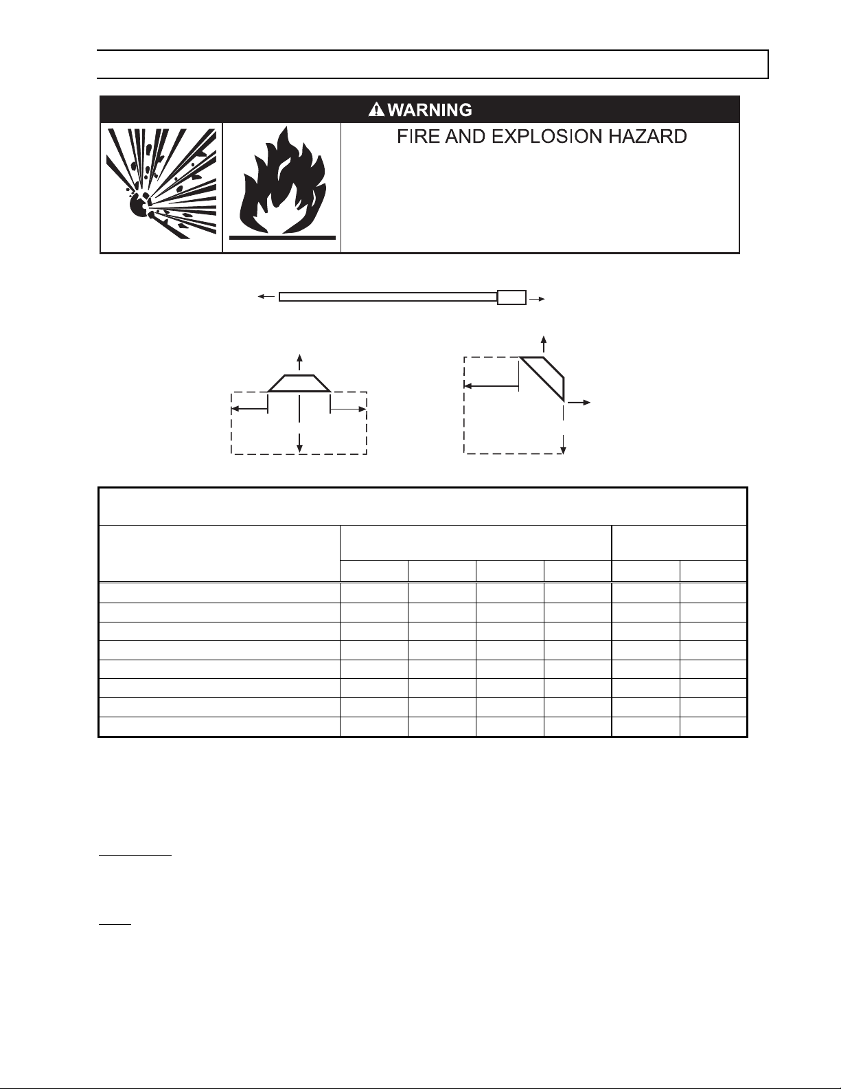
4.0) MINIMUM CLEARANCES TO COMBUSTIBLES
Combustible material must be located outside the
clearance dimensions listed.
Failure to do so may result in death, serious injury or
property damage.
Minimum clearances to combustibles shall be measured from the outer surfaces as shown in the following diagram:
End
End
* Ceiling
Ceiling
Side
Below
Horizontal
Side
Front
Below
45° Angle (Maximum)
Rear
MINIMUM CLEARANCES TO COMBUSTIBLES
Angle Mounted at
Model No.
PTS/PTU 40/25
PTS/PTU 50/30
PTS/PTU 75/50
PTS/PTU 100/65
PTS/PTU 125/80
PTS/PTU 150/100
PTS/PTU 175/110
PTS/PTU 200/125
Mounted Horizontally
Sides Ceiling* Below Ends 45º Front 45º Rear
27” 6” 40” 30” 48” 12”
27” 6” 40” 30” 48” 12”
27” 6” 60” 30” 48” 12”
66” 6” 88” ** 40” 66” 20”
66” 6” 101” ** 40” 66” 20”
84” 6” 106” ** 48” 84” 24”
84” 6” 106” ** 48” 84” 24”
84” 6” 106” ** 48” 84” 24”
45º
* When used indirect vented, minimum clearance for CEILING must be: 12” for PTS/PTU 50-75 and 18” for
PTS/PTU 100-200. If optional corner and u-bend reflectors are not used, the clearance must be 18”.
** Maximum clearance below reduces to 72” once you are 20ft. downstream from the control box.
WARNING
: Certain materials or objects, when stored under the heater, will be subjected to radiant heat and
could be seriously damaged. Observe the Minimum Clearances to Combustibles listed in the manual and on the
heater at all times.
NOTE
: The clearances specified above must be maintained to combustibles and other materials that may be
damaged by temperatures 90ºF above ambient temperature. Clearances to combustibles are posted on the
control box. In areas used for storage of combustible materials where they may be stacked below the heater,
NFPA54 requires that the installer must post signs that will “specify the maximum permissible stacking height to
maintain the required clearances from the heater to combustibles.” Space-Ray recommends posting these signs
adjacent to the heater thermostat or other suitable location that will provide enhanced visibility.
Form #43343530
–4– JJuly 08
Page 6
5.0) SPECIFICATIONS
High
Btu/hr
Model No.
PTS/PTU 40/25 40,000 25,000 #44140061 #32
PTS/PTU 50/30 50,000 30,000 #44140064 3.5mm
PTS/PTU 75/50 75,000 50,000 #44140063 #21
PTS/PTU 100/65 100,000 65,000 #44140062 #12
PTS/PTU 125/80 125,000 80,000 #44140066 #4
PTS/PTU 150/100 150,000 100,000 #44140067 “A”
PTS/PTU 175/110 175,000 110,000 #44140067 “E”
PTS/PTU 200/125 200,000 125,000 #44140068 6.9mm
Input
Low
Btu/hr
Input
Combustion
Air Plate
Part #
Natural Gas Propane Gas
Orifice Size
(0.116)
(0.138)
(0.159)
(0..189))
(0..209)
(0.234)
(0.250)
(0.272)
#49
46
2.5mm
#32
#30
#27
#23
4.1mm
(0.073)
(0.081)
(0.098)
(0.116)
(0.129)
(0.144)
(0.154)
(0.161)
Minimum *
Mounting Height
@
Horizonta
l
45º Angle
10 ft. 9 ft. 4
11 ft. 10 ft. 5
13 ft. 12 ft. 5
14 ft. 13 ft. 3
14 ft. 13 ft. 7
15 ft. 14 ft. 4
16 ft. 15 ft. 0
18 ft. 16 ft. 1
@
Turbulator
* MOUNT HEATERS AS HIGH AS POSSIBLE. Minimums are shown as a guideline for human comfort and uniform
energy distribution for complete building heating applications. Consult your Space-Ray representative for the
particulars of your installation requirements.
Type
Gas:
Natural
or Propane
Gas-Pipe
Connection:
Diameter:
Tube
Flue
Connection: 1
Fresh Air
Connection: 1
½” MPT
(Male) 4” 4” Round 4” Round
Electrical
Supply:
Current
Rating:
120 Volt,
60Hz, 1 Phase 1.74 Amp
1) See Section 16 for vent sizes when multiple heaters are connected into a common vent.
Module Electrical Rating:
Input Power-Control: 18-30 VAC 50/60 Hz (class 2
transformer)
Input Power-Line: 120 VAC (L1, IND contacts only)
Gas Valve Rating: 2.0 A @ 24 VAC (max.)
Combustion Blower Rating: 3.0 FLA @ 120 VAC
Ignition System (direct spark):
15 second trial for ignition period
15 second pre-purge period
60 second inter-purge period
30 second post-purge period
3 tries for ignition (separate flame sensor).
1/4 H.P. Motor
Flame Sensitivity: 0.7 microamps minimum
Qty.
6.0) PACKING LIST
A) PTS/PTU Burner Package QTY
Burner Box Assembly (Refer to the following chart for Package Part Numbers) 1
4”ID x 4”Lg Flue Adapter Collar (#30504500) ...................................................................1
Fastener Kit – Burner Box Attachment/Flue Adapter Collar (#42907040)....................1
containing
¼ - 20 Locknuts (#02167010)..............................................................3
Tube Flange Gasket (#42921000).......................................................................................1
Turbulator 24” Long (#44152240) *See chart above for required quantities. *
Installation & Operation Instructions (#43343530)..........................................................1
Turnbuckle (#30545040) ......................................................................................................1
Gas connector 5/8” OD x 36” (#30302360) .......................................................................1
Form #43343530
July 08 –5–
: #10 x 1/2” Self-Drilling Screws (#02189020)..............................2
Page 7
BURNER PACKAGE NUMBERS:
NATURAL GAS PROPANE GAS
MODEL NO PART NO.
PTS/U 40-N7 #44149510
PTS/U 50-N7 #44149530
PTS/U 75-N7 #44149550
PTS/U 100-N7 #44149570
PTS/U 125-N7 #44149590
PTS/U 150-N7 #44149610
PTS/U 175-N7 #44149630
PTS/U 200-N7 #44149650
MODEL NO
PART NO.
PTS/U 40-L7 #44149520
PTS/U 50-L7 #44149540
PTS/U 75-L7 #44149560
PTS/U 100-L7 #44149580
PTS/U 125-L7 #44149600
PTS/U 150-L7 #44149620
PTS/U 175-L7 #44149640
PTS/U 200-L7 #44149660
B) PTS 40-200 Body Package Descriptions
(Package Part Number is indicated on the outside of each corresponding carton.)
System Lengths
PTS Body Packages – Aluminized/Hot Rolled or
Alumi-Therm/Hot Rolled
10 Ft.
44134020
20 Ft. pkg
44135000
30 Ft. pkg
44136000
40 Ft. pkg
44137100
50 Ft. pkg
44138100
Part # Each Body Package Includes: Qty. Qty. Qty. Qty. Qty.
42912080 10 Ft. Tube with 24 Hole Flange (Aluminized) 1 1 1 - 42912169 10 Ft. Tube with 6 Hole Flange (Alumi-Therm) - - - 1 1
41932101 10 Ft. Tube less Flanges (Hot Rolled) - 1 2 3 4
43319100 Reflector, 9’ 11½” 1 2 3 4 5
30462980 Tube Coupling - 1 2 3 4
43318000 Tube Hanger/Support Bracket, 13” 1 2 3 4 5
43980010 Wire Hanger 1 2 3 4 5
Body Fastener Kit (included in body packages) 42907280 42907190 42907200 42907210 42907220
42873000 U-Bolt 1 2 3 4 5
02127110 Hex Nut, 5/16-18 3 5 6 8 10
02189020 HWHSM Screw, #10-16 x ½” TEKS 4 8 10 14 18
60Ft. System 70Ft. System
PTS Body Packages – Alumi-Therm/Hot Rolled
40 Ft. Pkg
44137100
20 Ft. Pkg
44135010
40 Ft. Pkg.
44137100
30 Ft. Pkg
44136040
Part # Each Body Package Includes: Qty. Qty. Qty. Qty.
42912169 10 Ft. Tube with 6 Hole Flange (Alumi-Therm)
1 - 1 41932101 10 Ft. Tube less Flanges (Hot Rolled) 3 2 3 3
43319100 Reflector, 9’ 11½” 4 2 4 3
30462980 Tube Coupling 3 2 3 3
43318000 Tube Hanger/Support Bracket, 13” 4 2 4 3
43980010 Wire Hanger 4 2
4 3
Body Fastener Kit (included in body packages) 42907210 42907190 42907210 42907200
42873000 U-Bolt 4 2 4 3
02127110 Hex Nut, 5/16-18 8 5 8 6
02189020 HWHSM Screw, #10-16 x ½” TEKS 14 8
14 10
Form #43343530
–6– JJuly 08
Page 8
C) PTS 40-200 Series Body Package Descriptions – ALC Option (Aluminized Calorized)
(Package Part Number is indicated on the outside of carton.)
System Lengths
PTS Body Packages – Aluminized/Aluminized or
Alumi-Therm/Aluminized
10 Ft. Pkg
44134020
20 Ft. Pkg
44135020
30 Ft. Pkg
44136020
40 Ft. Pkg
44137090
50 Ft. Pkg
44138080
Part # Each Body Package Includes: Qty. Qty. Qty. Qty. Qty.
42912080 10 Ft. Tube with 24 Hole Flange (Aluminized) 1 1 1 - 42912169 10 Ft. Tube with 6 Hole Flange (Alumi-Therm) - - - 1 1
41932100 10 Ft. Tube less Flanges (Aluminized) - 1 2 3 4
43319100 Reflector, 9’ 11½” 1 2 3 4 5
30462980 Tube Coupling - 1 2 3 4
43318000 Tube Hanger/Support Bracket, 13” 1 2 3 4 5
43980010 Wire Hanger 1 2 3 4 5
Body Fastener Kit (included in body packages) 42907280 42907190 42907200 42907210 42907220
42873000 U-Bolt 1 2 3 4 5
02127110 Hex Nut, 5/16-18 3 5 6 8 10
02189020 HWHSM Screw, #10-16 x ½” TEKS 4 8 10 14 18
60Ft. System 70Ft. System
PTS Body Packages – Alumi-Therm/Aluminized
40 Ft. Pkg
44137090
20 Ft. Pkg
44135030
40 Ft. Pkg
44137090
30 Ft. Pkg
44136050
Part # Each Body Package Includes: Qty. Qty.
42912169 10 Ft. Tube with 6 Hole Flange (Alumi-Therm)
1 - 1 -
Qty. Qty.
41932100 10 Ft. Tube less Flanges (Aluminized) 3 2 3 3
43319100 Reflector, 9’ 11½” 4 2 4 3
30462980 Tube Coupling 3 1 3 3
43318000 Tube Hanger/Support Bracket, 13” 4 2 4 3
43980010 Wire Hanger 4 2
4 3
Body Fastener Kit (included in body packages) 42907210 42907190 42907210 42907200
42873000 U-Bolt 4 2 4 3
02127110 Hex Nut, 5/16-18 8 5 8 6
02189020 HWHSM Screw, #10-16 x ½” TEKS 14 8
14 10
D) PTU 40-200 Body Package Descriptions
(Package Part Number is indicated on the outside of each corresponding carton.)
System Lengths
PTU Body Packages – Aluminized/Hot Rolled or
Alumi-Therm/Hot Rolled
20 Ft. Pkg.
44135000
30 Ft. Pkg
44136010
40 Ft. Pkg
44137100
50 Ft. Pkg
44138110
Part # Each Body Package Includes: Qty. Qty. Qty. Qty.
42912080 10 Ft. Tube with 24 Hole Flange (Aluminized) 1 1 - 42912169 10 Ft. Tube with 6 Hole Flange (Alumi-Therm) - - 1 1
41932101 10 Ft. Tube less Flanges (Hot Rolled) 1 1 3 3
41932051 5 Ft. Tube less Flanges (Hot Rolled) - 2 - 2
43319100 Reflector, 9’ 11½” 2 2 4 4
43319050 Reflector, 4’ 11 ½” - 2 - 2
30462980 Tube Coupling 1 3 3 5
43318000 Tube Hanger/Support Bracket, 13” 2 4 4 6
43980010 Wire Hanger 2 4 4 6
Form #43343530
July 08 –7–
Page 9
Body Fastener Kit (included in body packages) 42907190 42907210 42907210 42907221
42873000 U-Bolt 2 4 4 6
02127110 Hex Nut, 5/16-18 5 8 8 13
02189020 HWHSM Screw, #10-16 x ½” TEKS 8 14 14 24
U-Bend Package 43208020 43208020 43208020 43208020
42873000 U-Bend 1 1 1 1
43318500 31” Tube Support/Hanger Bracket 1 1 1 1
30462980 Tube Coupling 1 1 1 1
02189020 HWHSM Screw, #10-16 x ½” TEKS 2 2 2 2
60Ft. System 70Ft. System
PTU Body Packages – Alumi-Therm/Hot Rolled
40 Ft. Pkg.
44137100
20 Ft. Pkg.
44135010
40 Ft. Pkg.
44137120
30 Ft. Pkg.
44136040
Part # Each Body Package Includes: Qty. Qty. Qty. Qty.
42912169 10 Ft. Tube with 6 Hole Flange (Alumi-Therm)
1 - 1 41932101 10 Ft. Tube less Flanges (Hot Rolled) 3 2 2 3
41932051 5 Ft. Tube less Flanges (Hot Rolled) - - 2 43319100 Reflector, 9’ 11½” 4 2 3 3
43319050 Reflector, 4’ 11 ½’ - - 2 30462980 Tube Coupling 3 2 4 3
43318000 Tube Hanger/Support Bracket, 13” 4 2 5 3
43980010 Wire Hanger 4 2
5 3
Body Fastener Kit (included in body packages) 42907210 42907219 42907220 42907200
42873000 U-Bolt 4 2 5 3
02127110 Hex Nut, 5/16-18 8 5 10 6
02189020 HWHSM Screw, #10-16 x ½” TEKS 14 8
18 10
U-Bend Package 43208020 43208020
42873000 U-Bend 1 1
43318500 31” Tube Support/Hanger Bracket 1 1
30462980 Tube Coupling 1 1
02189020 HWHSM Screw, #10-16 x ½” TEKS 2
2
E) PTU 40-200 Series Body Package Descriptions – ALC Option (Aluminized Calorized)
(Package Part Number is indicated on the outside of each corresponding carton.)
System Lengths
PTU Body Packages –Aluminized/Aluminized or
Alumi-Therm/Aluminized
20 Ft. Pkg.
44135020
30 Ft. Pkg.
44136030
40 Ft. Pkg.
44137090
50 Ft. Pkg.
44138090
Part # Each Body Package Includes: Qty. Qty. Qty. Qty.
42912080 10 Ft. Tube with 24 Hole Flange (Aluminized) 1 1 - 42912169 10 Ft. Tube with 6 Hole Flange (Alumi-Therm) - - 1 1
41932100 10 Ft. Tube less Flanges (Aluminized) 1 1 3 3
41932050 5 Ft. Tube less Flanges (Aluminized) - 2 - 2
43319100 Reflector, 9’ 11½” 2 2 4 4
43319050 Reflector, 4’ 11 ½” - 2 - 2
30462980 Tube Coupling 1 3 3 5
43318000 Tube Hanger/Support Bracket, 13” 2 4 4 6
43980010 Wire Hanger 2 4 4 6
Form #43343530
–8– JJuly 08
Page 10

13
(33cm)
13
(33cm)
6
(15cm)
12
(30cm)
END REFLECTOR
Body Fastener Kit (included in body packages) 42907190 42907210 42907210 42907221
42873000 U-Bolt 2 4 4 6
02127110 Hex Nut, 5/16-18 5 8 8 13
02189020 HWHSM Screw, #10-16 x ½” TEKS 8 14 14 24
U-Bend Package 43208020 43208020 43208020 43208020
42873000 U-Bend 1 1 1 1
43318500 31” Tube Support/Hanger Bracket 1 1 1 1
30462980 Tube Coupling 1 1 1 1
02189020 HWHSM Screw, #10-16 x ½” TEKS 2 2 2 2
60Ft. System 70Ft. System
PTU Body Packages – Alumi-Therm/Aluminized
40 Ft. Pkg.
44137090
20 Ft. Pkg.
44135030
40 Ft. Pkg.
44137110
30 Ft. Pkg.
44136050
Part # Each Body Package Includes: Qty. Qty. Qty. Qty.
42912169 10 Ft. Tube with 6 Hole Flange (Alumi-Therm) 1 - 1 41932100 10 Ft. Tube less Flanges (Aluminized) 3 2 2 3
41932050 5 Ft. Tube less Flanges (Aluminized) - - 2 43319100 Reflector, 9’ 11½” 4 2 3 3
43319050 Reflector, 4’ 11 ½’ - - 2 30462980 Tube Coupling 3 2 4 3
43318000 Tube Hanger/Support Bracket, 13” 4 2 5 3
43980010 Wire Hanger 4 2
5 3
Body Fastener Kit (included in body packages) 42907210 42907219 42907220 42907200
42873000 U-Bolt 4 2 5 3
02127110 Hex Nut, 5/16-18 8 5 10 6
02189020 HWHSM Screw, #10-16 x ½” TEKS 14 8
18 10
U-Bend Package 43208020 43208020
42873000 U-Bend 1 1
43318500 31” Tube Support/Hanger Bracket 1 1
30462980 Tube Coupling 1 1
02189020 HWHSM Screw, #10-16 x ½” TEKS 2
2
6.1) ACCESSORIES
A) End Reflector Accessory Package, Part #43341010
(1 pkg. per PTS Series or 2 pkgs. per PTU Series)
Contains
End Reflector, #43320000……QTY–2
Speed Clips, #02266010……QTY–4
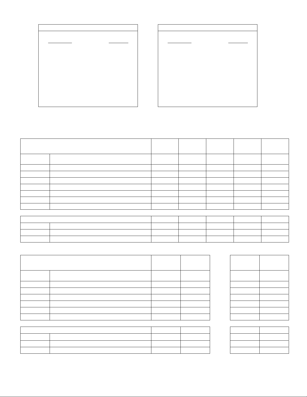
B) Elbow Accessory Package, Part #43208010
Form #43343530
July 08 –9–
(Option for PTS Series Only)
Contains
Elbow, #431750010……QTY–1
#10-16 x ½ Self-Drilling Screws, #02189020……QTY–2
Tube Coupling, #30462980……QTY–1
:
:
Page 11
18
(46cm)
30 3/4 (78cm)
Length = 24 (61cm)
C) Corner Reflector Accessory Package, Part #43342000
(Option for PTS Series Only)
Contains
:
Corner Reflector Assembly, #43345000……QTY–1
Speed Clips, #02266010……QTY–4
24
(61cm)
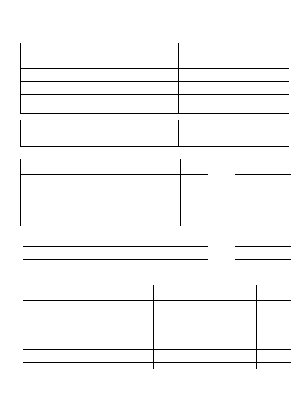
D) U-Bend Package, Part #43208020
(Option for PTU Series Only)
Contains:
U-Bend, #42913020……QTY–1
#10-16 x ½ Self-Drilling Screws, #02189020……QTY–2
Tube Coupling, #30462980……QTY–1
31” Hanger/Tube Support, #43318500……QTY–1
E) U-Bend Reflector Package, Part #43488000
(Option for PTU Series Only)
Contains:
U-Bend Reflector, #43490000……QTY–1
U-Bend End Reflector, #43490050……QTY–1
Speed Clips, #02266010……QTY–11
#10-16 x ½ Self-Drilling Screws, #02189020……QTY–4
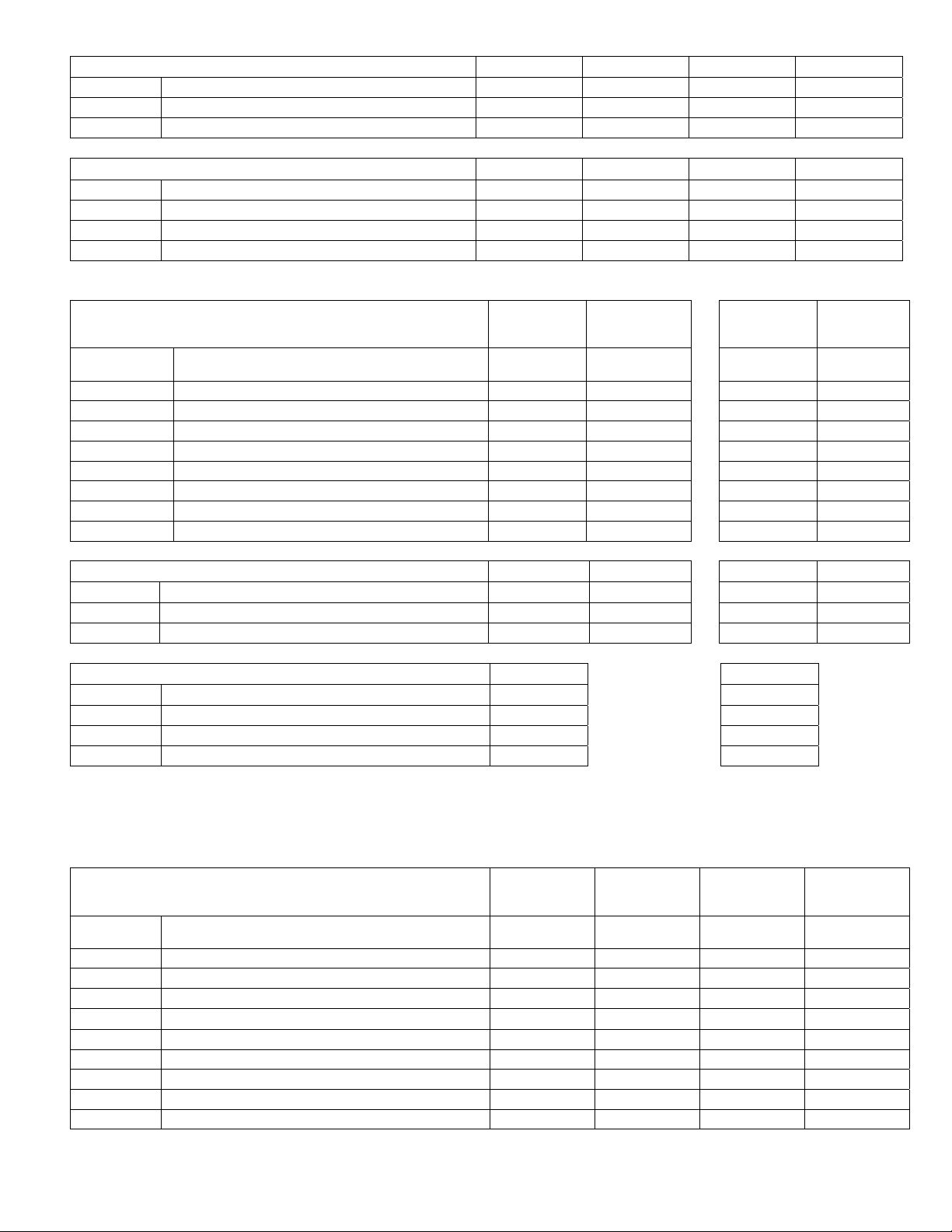
F) 31” Hanger/Tube Support, Part #43318500
(Option for Angle Mounting of PTU Series)
31
(79cm)
18
(46cm)
Tube Centers
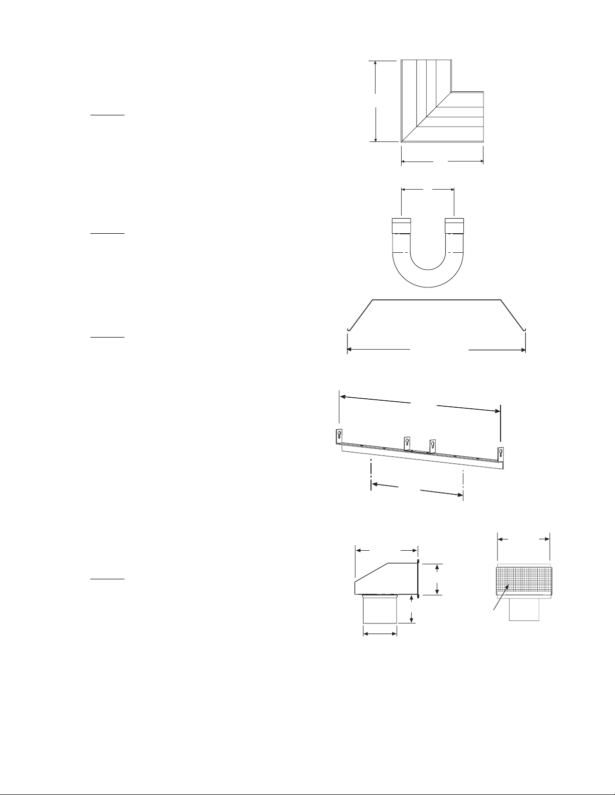
G) Exhaust Hood Package, Part #42924000
Contains
Exhaust Hood Assembly, #42925540……QTY–1
#10-16 x ½ Self-Drilling Screws, #02189020……QTY–2
:
4 (10cm)
7 1/2
(19cm)
3 3/4 (10cm)
3 1/2 (9cm)
Side View
24
(61cm)
7 1/2
(19cm)
Bird
Screen
Front View
Form #43343530
–10– JJuly 08
Page 12
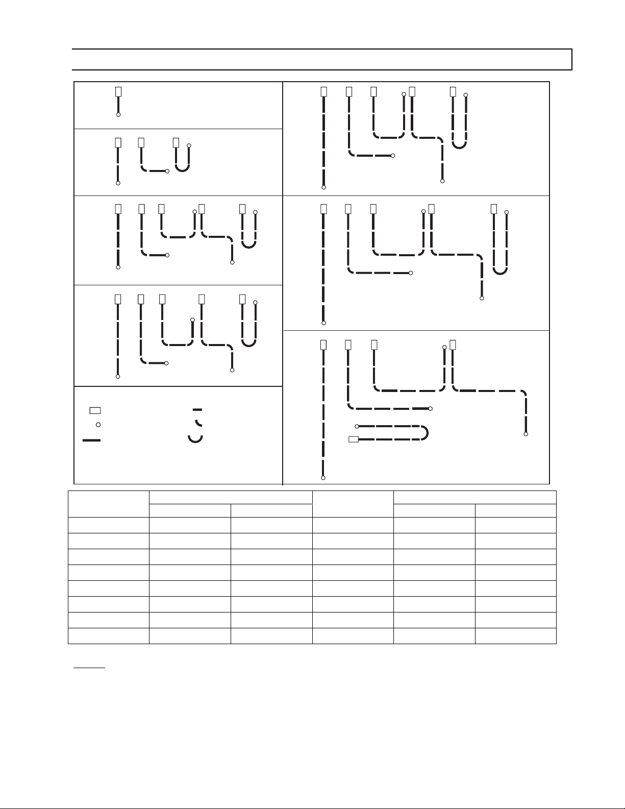
7.0) TYPICAL LAYOUTS – PTU / PTS Series
10FT.
SYSTEM
50 FT.
SYSTEM
20 FT.
SYSTEM
30 FT.
SYSTEM
60 FT.
SYSTEM
40 FT.
SYSTEM
LEGEND
Burner Box
Flue Termination
10 FT. Body Section
5 FT. Body Section
90 Deg. Elbow
180 Deg. U-Bend
70 FT.
SYSTEM
EMITTER LENGTH BODY LENGTH
MODEL
PTS 40/25
PTS 50/30
PTS 75/50
PTS 100/65
PTS 125/80
PTS 150/100
PTS 175/110
PTS 200/125
Min. Max.
10 Ft. 20 Ft.
20 Ft 30 Ft.
20 Ft. 30 Ft.
30 Ft. 40 Ft.
30 Ft 50 Ft.
40 Ft. 60 Ft.
50 Ft. 70 Ft.
50 Ft. 70 Ft.
MODEL
PTU 40/25
PTU 50/30
PTU 75/50
PTU 100/65
PTU 125/80
PTU 150/100
PTU 175/110
PTU 200/125
Min. Max.
10 Ft. 10 Ft.
10 Ft. 15 Ft.
10 Ft. 15 Ft
15 Ft. 20 Ft.
15 Ft. 25 Ft.
20 Ft. 30 Ft.
25 Ft. 35 Ft.
25 Ft. 35 Ft.
NOTES:
1) In all configurations, the control unit must be connected directly to either a) the 24-hole flange of the 10 ft.
aluminized steel starting body section (for 10 ft., 20 ft., and 30 ft. systems) or b) the 6-hole flange of the 10 ft.
alumi-therm steel starting body section (for 40 ft., 50 ft., 60 ft., and 70 ft. systems.
2) Joining of two 90º elbows directly together to form a “Z” shape IS NOT permitted.
3) PTS / U 175/110 - 40 ft length available for special applications.
4) 5 Ft. Body Packages may be utilized on any of these heaters to yield heater lengths from 15 ft. to 70 ft.
5) Any configuration of components not shown in the illustrations may be used except as noted in 1 and 2
Form #43343530
July 08 –11–
Page 13
above.
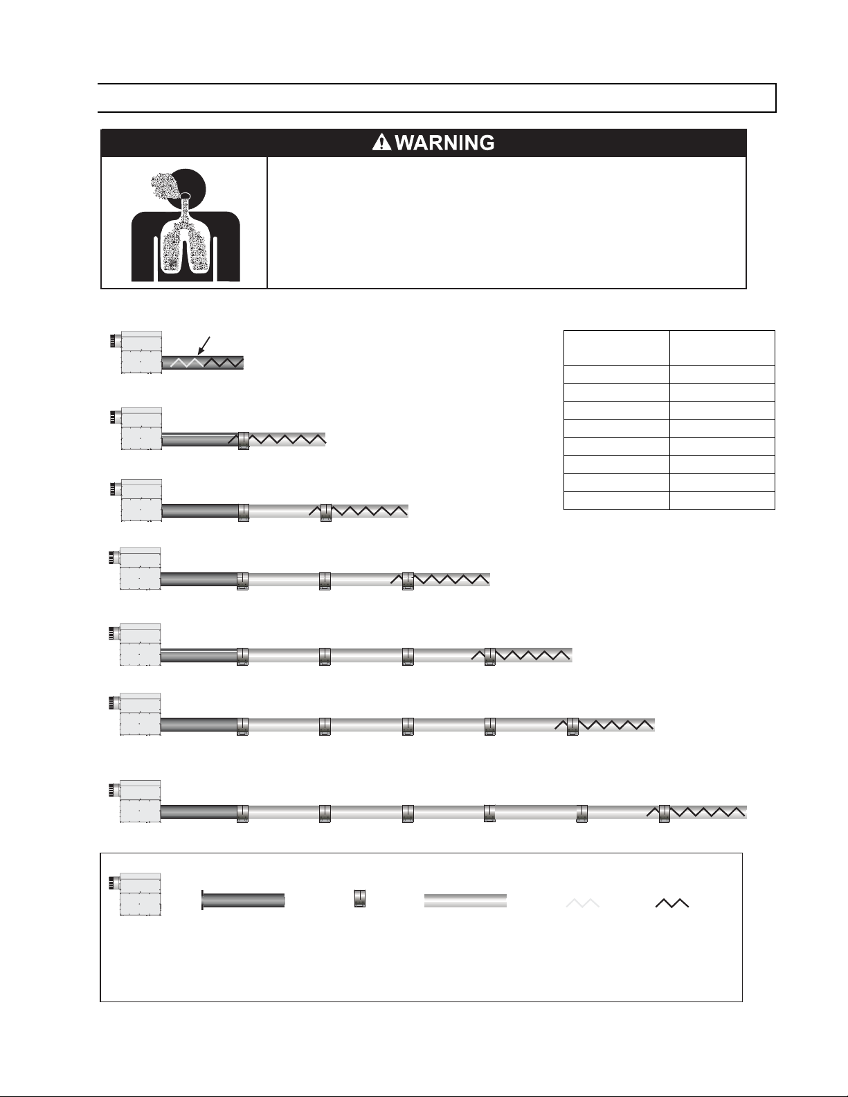
7.1) TYPICAL ASSEMBLY LAYOUT
POISONOUS GAS AND SOOT HAZARD
The heater must be assembled with the correct number of turbulator sections
and tube length for the rated heat input.
The turbulator must be installed in the last tube section as shown.
Failure to do so may result in death, serious injury, property damage or illness
from Carbon Monoxide poisoning.
10 FT. SYSTEM
20 FT. SYSTEM
30 FT. SYSTEM
40 FT. SYSTEM
50 FT. SYSTEM
60 FT. SYSTEM
70 FT. SYSTEM
Burner Box 10ft Aluminized Tube 24
Form #43343530
–12– JJuly 08
Stainless Steel Turbulator
closest to burner PTS / U
40 only.
Hole Flange
or
10ft Alumi-Therm Tube
6 Hole Flange
LEGEND
Coupling 10ft Aluminized or HRS
Tube model dependent
MODEL
PTS/U 40/25
PTS/U 50/30
PTS/U 75/50
PTS/U 100/65
PTS/U 125/80
PTS/U 150/100
PTS/U 175/110
PTS/U 200/125
2ft Stainless
Steel
Turbulator
sections
2 Ft. Turbulator
Sections
2ft Aluminized
Steel
Turbulator
sections
4
5
5
3
7
4
0
1
Page 14
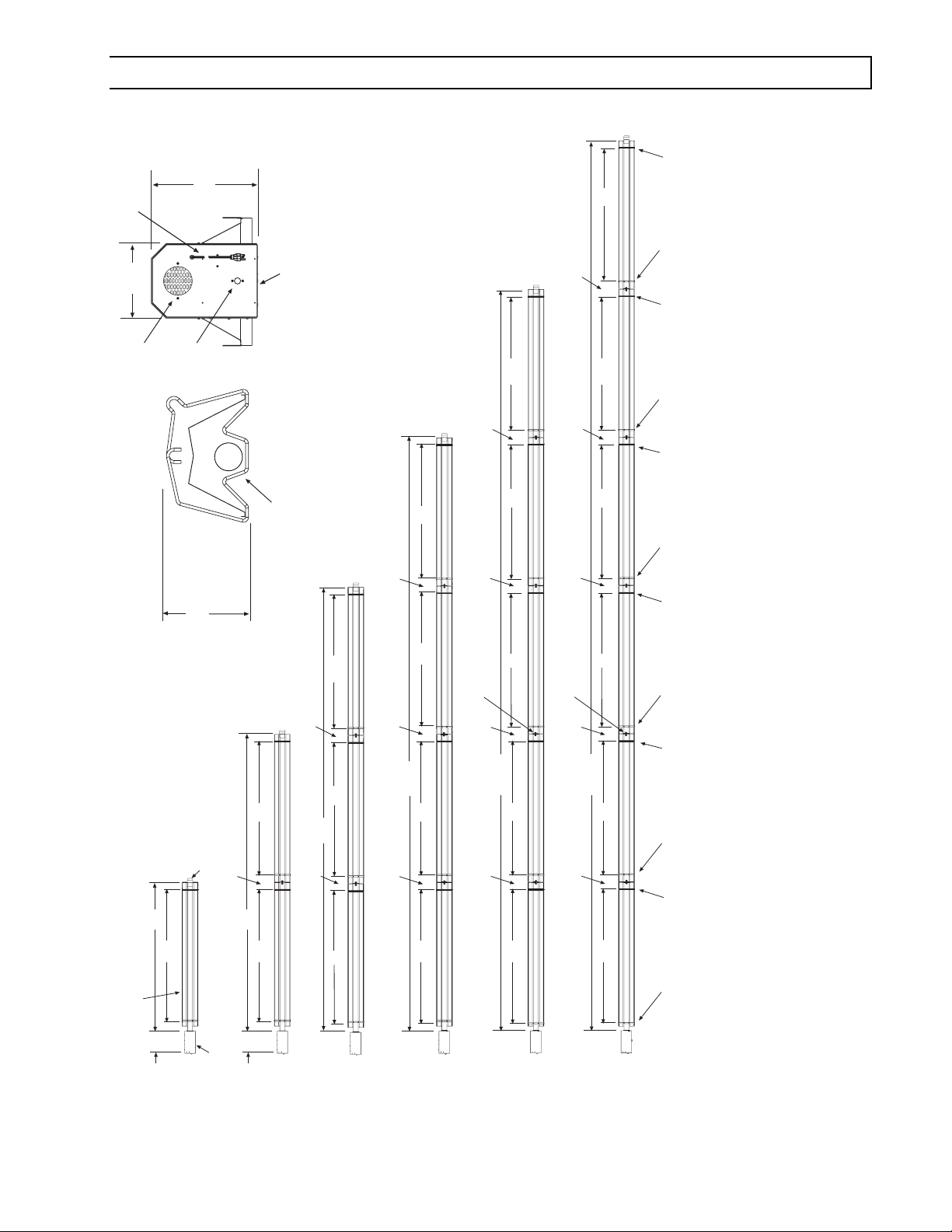
8.0) DIMENSIONS – PTS Series
Typical Dimensions Up to 60 Ft. Shown.
120VAC
Power Supply Cord
10
(25cm)
Fresh Air
Inlet
1/2 MPT Gas
(37cm)
14-1/2
Connection
9-1/4
(24cm)
Burner
Box
End View
Flue Terminal
12
(30cm)
108
(274cm)
12
12
(30cm)
(30cm)
108
108
(274cm)
(274cm)
12
12
(30cm)
(30cm)
108
108
108
(274cm)
(274cm)
(274cm)
Wire Hanger
13 Tube Support/
Hanger Bracket
Wire Hanger
13 Tube Support/
Hanger Bracket
Wire Hanger
13 Tube Support/
Hanger Bracket
Wire Hanger
10 FT Tube
Assembly
120
(typical)
14
(305cm)
108
(274cm)
(36cm)
Models:
PTS 40
Flue
Terminal
Burner
Box
12
(30cm)
240
(610cm)
14
108
(274cm)
108
(274cm)
(36cm)
Models:
PTS 40, 50,
75
12
12
(30cm)
360
(30cm)
108
(274cm)
108
(274cm)
(914cm)
108
(274cm)
Models:
12
12
PTS 50, 75,
100, 125
(30cm)
480
(30cm)
108
(274cm)
(1219cm)
108
(274cm)
108
(274cm)
Models:
PTS 100, 125
150
108
4 Tube Coupling
(typical)
12
(30cm)
600
(1524cm)
108
12
(30cm)
108
(274cm)
(274cm)
(274cm)
Models:
PTS 125, 150,
175, 200
4 Tube Coupling
(typical)
12
(30cm)
720
12
(30cm)
Bottom View
108
(274cm)
(1829cm)
108
(274cm)
108
(274cm)
Models:
PTS 150, 175,
200
13 Tube Support/
Wire Hanger
13 Tube Support/
Wire Hanger
Bottom View
13 Tube Support/
Hanger Bracket
Hanger Bracket
Hanger Bracket
Form #43343530
July 08 –13–
Page 15
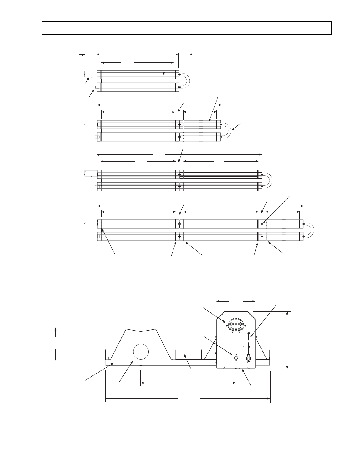
8.1) DIMENSIONS – PTU Series
Typical Dimensions Up to 50 Ft. Shown.
(36cm)
Models:
PTU 40, 50,
75
Models:
PTU 50, 75,
100, 125
Models:
PTU 100, 125,
150, 175
Models:
PTU 125, 150,
175, 200
14
Burner
Box
Flue
Terminal
(274cm)
(305cm)
108
180
(457cm)
(274cm)
108
(274cm)
120
108
(274cm)
108
240
(610cm)
12
(30cm)
12
(30cm)
12
(30cm)
15
(38cm)
10 FT Tube
Assembly
(typical)
48
(122cm)
300
(762cm)
5 FT Tube
Assembly
108
(274cm)
(274cm)
108
U-Bend
12
(30cm)
(122cm)
4 Tube Coupling
(typical)
48
6
(16cm)
31 Tube Support/
Hanger Bracket
Bottom View
31 Tube Support/
Hanger Brackets
(typical at control end)
Shipped with
U-Bend Package
Flue Terminal
Wire Hangers
(typical)
1/2 MPT Gas
Connection
18 (46cm)
31 (79cm)
PTU (end view)
13 Tube Support/
Hanger Brackets
(typical)
Fresh Air
Inlet
U-Bend
10
(25cm)
Wire Hangers
(typical)
120VAC
Power Supply Cord
Burner
Box
13 Tube Support/
Hanger Brackets
(typical)
14-1/2
(37cm)
Form #43343530
–14– JJuly 08
Page 16
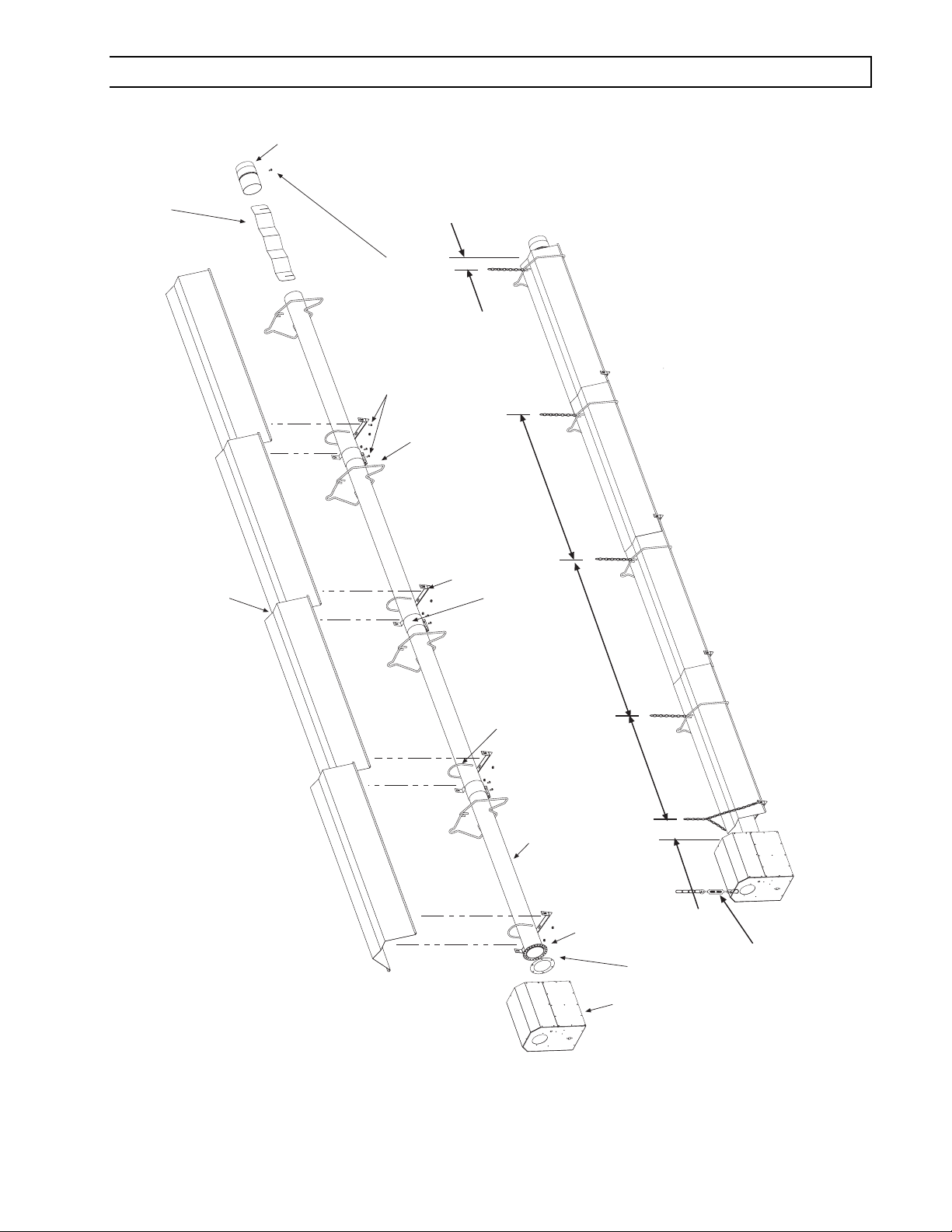
8.2) HEATER ASSEMBLY / JOINING OF TUBE SECTIONS
a
Flue
Termin
Turbulator
(See specifications
section 5 for required
quantities.)
Typical
Overlap
Not Less
Than 10
#10 Self-Drill Screws
(Typical all tube supports,
tube couplings and flue
terminal.)
Wire Hanger
Tube Support Bracket
Tube Coupling
)
.
8 - 10
(Typical each tube joint
8 - 10
5 hanging points to be used for suspension for a typical 40ft
long system. There must be two hanging points on the first
tube and one on each of the other tubes
U-Bolt Clamp &
5/16" Hex Nuts
Tube
7
8 - 9 ¼
4"OD x 10Ft.
for required tubes.
See section
Flange
24 Hole for Aluminized Steel Tubes
6 Hole for Alumi-Therm Steel Tubes
Mounting
Gasket
(PTS 40FT Shown)
Burner
Box
Maximum 6 distance
from burner box to the
Typical Assembly Overview
tube support/hanger
Burner Box
bracket.
Suspension
Chain
Form #43343530
July 08 –15–
Page 17

Typical Assembly Overview
(PTU 40FT Shown)
Turbulator
(See specifications
section 5 for required
quantities.)
#10 Self-Drill
Screws
(2 each)
Flue
Terminal
Burner Box
Gasket
Typical
Overlap
31 Tube Support Brk.
with U-Bolt Clamp
& 5/16" Hex Nuts
Mounting Flange
24 Hole for Aluminized Steel Tubes
6 Hole for Alumi-Therm Steel Tubes
Reflector
Wire Hanger
4"OD x 10Ft. Tube
See section 7
for required tubes.
13 Tube Support Brk.
with U-Bolt Clamp
& 5/16" Hex Nuts
U-Bend
Tube Coupling
(Typical each tube joint.)
#10 Self-Drill Screws
(Typical all tube supports,
tube couplings and flue
terminal.)
8 - 10
8 - 9 ¼
Maximum 6 distance
from burner box to the
tube support/hanger
bracket.
Burner Box
Suspension
Chain
6 hanging points to be used for suspension for a typical
40ft long system. There must be two hanging points
on the first tube and one on each of the other tubes
Form #43343530
–16– JJuly 08
Page 18

9.0) TYPICAL SUSPENSION METHODS
SUSPENSION HAZARD
Burner must be secured to the mounting flange with nuts.
All materials used to suspend the heater must have a minimum working load
of 115 lbs.
All S Hooks must be crimped closed.
Never use the heater to support a ladder or other access equipment.
Failure to do so may result in death, serious injury or property damage.
Various means of suspending the heater can be used. See the following drawings for typical examples.
1. Use only noncombustible materials for hangers and brackets.
2. A minimum No. 2 chain with a working load limit of 115 lbs. is required.
3. Turnbuckles can be used with chains to allow leveling of the heater. All “S” hooks and eye bolts must be
manually crimped closed by the installer.
4. When using rigid means for heater suspension (rod, flat bar, etc.) provide sufficient lengths or swing joints to
compensate for expansion. See Figures b and c.
5. Heaters subject to vibration must be provided with vibration isolating hangers.
6. Heaters must not be supported by gas or electric supply lines and must be suspended from a permanent
structure with adequate load capacity.
Space-Ray recommends that the body sections be suspended using chains with turnbuckles. This will allow slight
adjustments after assembly and heater expansion/ contraction during operation.
If a “trapeze” method is used (shown below), the minimum chain length for the two connecting chains is 36”. If these
chains must be less than 36”, then do not use the trapeze method and, instead, use individual chains on each tube
support/hanger bracket.
Minimum
No. 2 Chain
Eyebolt
Turnbuckle
Eyebolt
Failure to install the burner box suspension
chain will void the manufacturers warranty.
Turnbuckle
Minimum
No. 2 Chain
S-Hook crimped
closed (typical)
Wire Hanger
3/16 x 1
wideFlat Bar
Threaded
Rod
Turnbuckle
Eyebolt
Eye bolt
36 (91cm) Minimum
Burner Box Suspension
Form #43343530
July 08 –17–
a.
b.
Tube Support/
Hanger Bracket
c.
Wire
Hanger
d.
Page 19

10.0) ASSEMBLY OF TUBE SECTIONS
CUT HAZARD
Sheet metal parts, particularly reflectors and vent have sharp
edges. Always use gloves when handling.
Failure to do so may result in death, serious injury or property
damage.
During field assembly of the heater body sections, the recommended procedure is as follows:
1. Before hanging heater sections, first determine the actual layout of the system (see Sections 7.0 & 8.0 for
details). Consideration must also be taken for flue pipe, fresh air ducting, gas piping, clearances to combustibles,
etc. before hanging heater. Typical suspension methods are shown in Section 9.0.
2. Hang each tube section individually. DO NOT
attach the heater tube sections together on the ground and attempt
to hang the entire system.
3. In all configurations, the burner box must be connected directly to either a) the 24-hole flange of the 10 ft.
aluminized steel starting body section (for 10 ft., 20 ft., and 30 ft. systems) or b) the 6-hole flange of the 10 ft.
alumi-therm steel starting body section (for 40 ft., 50 ft., 60 ft., and 70 ft. systems.
4. Assemble a tube support/hanger bracket 4” from the end of the heat exchanger tube having the mounting
flange. Align the tube such that the welded seam is facing down toward the ground.
FAILURE TO ASSEMBLE THE TUBE WITH THE SEAM FACING DOWN
WILL VOID THE MANUFACTURER’S WARRANTY.
8 to 9 1/4
1
S Hooks
U-Bolt Clamp
& 5/16 Hex Nuts
Wire Hanger
2
4"OD x 10Ft. Heat
Treated Aluminized
Steel Tube
Tube Support/
Control Box
Mounting Flange
Maximum 6 distance from
control box mounting flange
to tube support bracket.
Hanger Bracket
5. Suspend the chain to attach the wire hanger and the tube support bracket. Insert the tube into the wire hanger
and then raise the tube support bracket end up to the suspension chain, use “S” hooks to attach the wire hanger
and tube support bracket to the chain.
Form #43343530
–18– JJuly 08
END VIEW
Weld seam to the
bottom of tube.
Page 20

10.1 ASSEMBLY OF EXTENSION SECTION
MIN 8 MAX 10 BETWEEN HANGERS
Coupling
1
2
Wire Hanger
U-Bolt Clamp
& 5/16 Hex Nuts
3
Tube Support/
Hanger Bracket
See typical assembly overview (Section 8.0) for typical complete assembly. Assemble additional extension
sections as required for all systems. (See Sections 7.0, and 8.0 for typical layout details.)
Join the tube sections together and secure with tube couplings as described below:
Tube Support/
Hanger Bracket
6 approx.
WARNING: THE FOLLOWING COUPLING TIGHTENING INSTRUCTIONS MUST
1. Place the compression coupling over the end of the tube.
2. Use the small hole at the centerline of the coupling to check that the coupling is inserted correctly.
3. Partially tighten the bolt nearest the end of the tube (approximately half closed).
BE FOLLOWED PROPERLY TO AVOID FUTURE PROBLEMS.
1
Tube
Center end of
Tube with hole
2
Tube
Coupling
Partially tighten this bolt
Form #43343530
July 08 –19–
3
Page 21

4
Center both
tubes with hole
Tube
Coupling
4. Slide the next tube into the coupling.
5. Make sure both tube ends are butted together.
6. Finish tightening both bolts to 40-60 ft.lbs. torque to ensure a complete seal.
7. Use the two Self-drilling screws through the pre-punched holes to secure the tubes in the coupling.
Band
#10 Self-Drilling
Screws
(QTY 2)
5
7
6
Force
Bars
Reaction
Block
8. Check to ensure that the hardware is completely closed and the band is seated on the reaction block and
interference pins as illustrated above.
9. Once all the heater body sections are attached, make sure that the heater system is level
adjustments can be made using the turnbuckles. (See Section 9.0)
Bolt
Interference
Pins
CORRECT
INSTALLATION
IMPORTANT: NEVER REUSE A COUPLING. Always install a new
coupling only and torque as per instructions above and the diagrams
above.
INCORRECT
INSTALLATION
. If it is not, slight
10.2) INSERTING TURBULATORS
POISONOUS GAS AND SOOT HAZARD
The heater must be assembled with the correct number of turbulator sections
and tube length for the rated heat input.
The turbulator must be installed in the last tube section as shown.
Failure to do so may result in death, serious injury, property damage or illness
from Carbon Monoxide poisoning.
1. Assemble the turbulators together by interlocking the slotted end portions. Slide these into the last tube
section until they are flush with the tube end. Note: Refer to the table below for quantities of turbulators
required for each heater model.
Form #43343530
–20– JJuly 08
Page 22

Turbulators
MODEL 2 Ft. Turbulator Sections
PTS/U 40/25
PTS/U 50/30
PTS/U 75/50
PTS/U 100/65
PTS/U 125/80
PTS/U 150/100
PTS/U 175/110
PTS/U 200/125
4
5
5
3
7
4
0
1
ASSEMBLY HAZARD
The PTS / U 40 has one stainless steel
turbulator. This must be installed
closest to the burner.
Failure to do so may result in
deterioration of the turbulator material
and invalidate the warranty.
10.3) ADDING REFLECTORS
1. Slide the reflectors on the tube support/hanger brackets and through the wire hangers.
2. The tube at the coupling joints must be covered. Slide the reflectors together and provide an overlap of two (2”)
inches for the first reflector overlap after the control unit. All remaining reflector overlaps will be approximately
one (1”) inch. This will allow for the natural expansion and contraction of the heater when in operation. Note: The
heaters can expand and contract up to 1-3/4” of an inch.
3. Secure the reflectors as shown in Detail “A” using #10 x 1/2” self-drilling sheet metal screws at each tube
support/hanger bracket.
40 FT SYSTEM SHOWN
The reflector overlap must be
able to slide at this joint for
expansion of the heater
3 Gap
(between burner box
and reflector)
2 OVERLAP
Burner Box
Suspension
Chain
BURNER
BOX
CORRECT INSTALLATION INCORRECT INSTALLATION
DETAIL A
REFLECTOR
OVERLAP
(offset from tube
hanger support brackets)
REFLECTOR
DETAIL B
DETAIL B
REFLECTOR
OVERLAP
(positioned over tube
hanger support brackets)
1 OVERLAP
1 OVERLAP
DETAIL A
#10 x 1/2 SHEET
METAL SCREW
(Typical all tube
hanger/
support brackets.)
FLUE
TERMINAL
Form #43343530
July 08 –21–
Page 23

11.0) ADDING OPTIONAL 90º ELBOW (PTS ONLY)
1. The optional 90º elbow must be located a minimum of 10 ft. after the control box.
2. Hang th e body secti ons in a 90º ( "L") sh aped pattern. Allow spacing for the elbow. The distance from one end of
the elbow to the centerline of the opposite leg is 13" as shown.
3. Join the tube ends of the body sections and the elbow together and secure with tube couplings as described in
Section 10.1.
Self-Drilling Screws
(QTY-2 per coupling)
13 (330mm)
Tube
Coupling
90 Deg. Elbow
13 (330mm)
11.1) ADDING OPTIONAL CORNER REFLECTOR (PTS ONLY)
1. Place the corner reflector over the reflectors of both body sections.
2. Secure by sliding speed clips on the reflector edges. One speed clip is required for each side of reflector.
3. The corner reflector can be used only when the long axis of the heater is level and mounted in a horizontal
position.
Speed Clip
(QTY-4)
Corner
Reflector
Form #43343530
–22– JJuly 08
Page 24

11.2) ADDING 180°U-Bend (PTU ONLY)
1. Hang body sections parallel with each other. The centerline distance from tube at each body section should be
18” as shown.
2. Join tube ends of body sections and the U-Bend together and secure with tube couplings as described in Section
10.1.
Self-Drilling Screws
(QTY-2 per coupling)
18
(457mm)
Tube Coupling
U-Bend
11.3) ADDING OPTIONAL U-BEND REFLECTOR (PTU ONLY)
1. Place the U-Bend Reflector over the reflectors of each body section with the end resting next to the tube wire
hangers as shown.
2. Slide the speed clips on the reflector edges towards the end of the body section reflectors. Two speed clips are
required for each side of the U-Bend Reflector. Make sure that the speed clips fit tightly over both the U-Bend
Reflector and the reflector on each body section. Use two self-drilling screws to permanently secure both sides to
the reflectors.
3. Place the End Reflector flush with the U-Bend Reflector as shown. Note: Clearance between end of the U-Bend
Reflector and the U-Bend must be a minimum of 1”. Secure by sliding speed clips onto the end reflector edges.
Evenly space the speed clips on the sides (two each side) and top (three each) of the reflectors to provide a snug
fit.
Form #43343530
July 08 –23–
U-Bend Reflector
Part No. 43490000
End Reflector
Part No. 43490050
Speed Clip
Part No. 02266010
(QTY-7)
1 Clearance
(between end reflector
and u-bend)
Speed Clip
Part No. 02266010
(QTY-4)
#10 Self-Drill Screws
Part No. 02189020
(QTY-4)
Wire Hangers
Page 25

12.0) ATTACHING BURNER BOX ASSEMBLY
1. Attach the burner box and gasket to end of tube flange and secure with 1/4-20 locknuts.
2. Assemble the optional end reflector flush with the end of the main body reflector. Secure by sliding speed clips
onto the reflector edges. Evenly space the speed clips on the sides (one each side) and top (two required) of the
reflectors to provide a snug fit. Leave a 3" space between the end reflector and the burner box assembly.
3. The heater can be mounted horizontally or at an angle of up to 45 degrees maximum from horizontal.
When angle mounting, the burner box unit must be positioned upright as shown below. FAILURE TO INSTALL THE
BURNER BOX IN AN UPRIGHT POSITION WILL VOID THE MANUFACTURER’S WARRANTY.
Speed Clip
(QTY-4)
DO NOT lift burner or support its
weight using the TISS wire. It will
break under heavy load.
Burner Box
Optional
End
Reflector
1/4-20 Locknut
(QTY-3 per flange)
Failure to install the burner box
suspension chain will void
manufacturers warranty.
Turnbuckle
Eye bolt
Burner Box Suspension
Tube Flange
Gasket
Upright Position
Burner
Box
Angle Mounting
Straight Tube Heaters
Reflector
Mounting Flange
24 Hole for Aluminized Steel Tubes
6 Hole for Alumi-Therm Steel Tubes
Upright Position
Burner
Box
Angle Mounting
U-Tube Heaters
Form #43343530
–24– JJuly 08
Page 26

12.1) CONNECTING THE TISS SYSTEM
Description: The TISS (Tube Integrity Safety System) is designed to shut the main burner off in the event that a
burnout occurs in the first 10ft. section of firing tube. Note: When replacing the firing tube a new TISS wire assembly
PN 44176010 must also be installed.
Instructions:
1. Make sure that the gap between the burner box and end of reflector is 3” and the reflector is securely
attached to the reflector support bracket. Make adjustments if necessary.
TISS Assembly.
#10 x 1/2 Screws
must securely attach
reflector to the bracket
3 Gap (between
burner box and end
of reflector)
Step 1
2. Un-roll the TISS wire assembly from the spool. Be careful not to kink the wires.
Spool with
TISS Wire
Assembly
Step 2
Form #43343530
July 08 –25–
Page 27

3. Hold the spring retainer clamp and pull the TISS wire assembly to end of reflector at overlap joint.
Slide spring retainer clamp over end of reflector as shown.
Step 3
Spring
Thimble
TISS Wire Assembly
PN 44176000
End View
Spring
Retainer Clamp
4. After attachment of the TISS, check to make sure that there is sufficient tension on the wire. Follow the
diagram below to increase or decrease the tension as necessary.
1. Measure the extension of the spring from the end of the reflector to the thimble as shown below.
11 extension
Thimble
Wire & Sleeving
Assembly
Wire & Sleeving
Assembly
Step 4
Spring
Retainer Clamp
Reflector End
2. Tape one end of the sleeve to the burner box
or use a marker.
3. Mark the other end of the sleeve with tape or
other marker. Use the top of the retainer as a
reference.
4. Loosen screws.
Spring
If the extension is less than 11 follow the
instruction below to increase the extension.
5. Pull one end of the sleeve and wire inside until
the marker is raised by the total adjusment length.
ie. if the extension is 10 then pull through 1 to
increase the exension to 11.
6. Tighten screws.
7. Check extension using the method in step 1.
Form #43343530
–26– JJuly 08
Page 28

ANGLE MOUNTED HEATERS ONLY
5. If heaters are to be angle mounted, the TISS wire holder clamp must first be re-positioned as shown
using the bottom hole pattern of the clamp. Follow procedures described earlier for all other
adjustments.
End View
Re-position wire clamp using
bottom hole pattern.
Angle Mounted Body Section
Step 5
Form #43343530
July 08 –27–
Page 29

13.0) GAS CONNECTIONS AND REGULATIONS
Tighten flexible gas hose and components securely.
Flexible metal gas hoses must be installed without any twists or
kinks in them. The hose will move during operation of the heater
and it can crack if it is twisted.
Failure to do so may result in death, serious injury or property
damage.
IMPORTANT BEFORE CONNECTING THE GAS TO THE HEATER
1. Connect to the supply tank or manifold in accordance with the latest edition of National Fuel Gas Code (ANSI
Z223.1), and local building codes. Authorities having jurisdiction should be consulted before the installation
is made. (In Canada, refer to the latest edition of CAN Standard B.149-1 & -2, Installation Codes for Gas
Burning Appliances and Equipment.)
2. Check that the gas fuel on the burner rating plate matches the fuel for the application.
3. Check that the gas supply piping has the capacity for the total gas consumption of the heaters and any other
equipment connected to the line.
4. Check that the calculated supply pressure with all gas appliances and heaters operating will not drop below
the minimum supply pressure required for these heaters. Check inlet supply pressures on Section 14.
5. All gas supply lines must be located in accordance with the required clearances to combustibles from the
heater as listed on the clearances label of the heater and section 4 of this manual.
6. Pipe joint compounds must be resistant to the action of liquefied petroleum gases.
7. Tube heaters will expand/contract during operation. Where local codes do not prohibit, a CSA or U.L.
approved flexible connector supplied with this heater is required for connections between the rigid piping
and the heater. A union should be installed before the burner box inlet. An approved shut off valve should
be installed within 6 feet of the union.
8. The gas pipe, flexible hose and connections must be self supporting. The gas pipe work must not bear any of
the weight of the heater or any other suspended assembly.
9. This appliance is equipped with a step-opening, combination gas valve. The maximum supply pressure to
the appliance is 14” W.C. or 1/2 P.S.I. If the line pressure is more than the maximum supply pressure, then
a second stage regulator which corresponds to the supply pressure must be used.
10. After all gas connections have been made, make sure the heater and all gas outlets are turned off before
the main gas supply is turned on slowly. Turn the gas supply pressure on and check for leaks. To check for
leaks, check by one of the methods listed in Appendix D of the National Fuel Gas Code.
11. If a 2
DO NOT USE AN OPEN FLAME OF ANY KIND TO TEST FOR
nd
stage regulator is used, the ball valve down stream in the supply line must be closed when purging
the gas lines to prevent gas seeping through it. If initial gas pressure is higher than 14” w.c. the redundant
combination gas valve is designed to lock out. Pressure build-up in the supply lines prior to the heater must
be released before proper heater operation.
LEAKS.
Form #43343530
–28– JJuly 08
Page 30

KEY DIMENSIONS AND COMPONENTS OF THE GAS CONNECTIONS
Gas Pressure
Approved
Flexible Connector
14 to 17
(36 to 43cm)
2 (5cm) Max.
Displacement
*Second Stage Regulator with
Vent Leak Limiter to reduce the
Supply Pressure below 14 W.C.
* Available as Accessories
Burner Movement
RECOMMENDED GAS CONNECTION POSITIONS WITH 36 FLEXIBLE GAS HOSE
Alternate Positions
DO NOT install gas connector
vertically if fresh air is to be
connected.
Adaptor 1/2 NPT male
= 2 PSIG
Gas Supply
Piping
*Manual Gas
Shut Off Valve
Sediment Trap
(Drip Leg)
7 5/8
3 7/8 (10cm)
Adaptor 1/2 NPT female
6
END VIEW
Gas pipe work must not restrict
opening of hinged service doors.
Burner Movement
Minimum 1 (25cm)
SIDE VIEW
Certified connectors are recommended to be installed as shown, in one plane, and without sharp bends, kinks or
twists.
INCORRECT POSITIONS
Movement
Movement
WRONG
WRONG
Movement
WRONG
Movement
WRONG
Form #43343530
July 08 –29–
Page 31

14.0) INSTRUCTIONS FOR PRESSURE TEST GAUGE CONNECTION
Never operate the heater with the access panel open or removed.
The access panels must be closed tightly with all the necessary
screws during operation.
Failure to do so may result in death, serious injury or property
damage.
The access doors on either side of the burner must
be securely fastened before operating the heater.
DANGER
FIRE HAZARD
Never operate the heater with the
access panel open or removed.
This access panel must be closed
tightly with all the necessary screws
during operation.
Failure to do so may result in death,
serious injury or property damage
43269050 Rev. A 03/08
SIDE VIEW
SUPPLY PRESSURE
1. The installer will provide a 1/8” N.P.T. tapped plug, accessible for test gauge connection immediately upstream
of the gas supply connection to the heater.
MANIFOLD PRESSURE– COMBINATION GAS VALVE IS FACTORY SET
Two-stage valves require that you check and adjust both high and low pressure regulator settings.
1. Turn the gas valve to the “OFF” position. Remove the 1/8” plug from the combination gas valve at the outlet
pressure tap and connect a 1/8” nipple to the tapped hole. Connect the gauge to the nipple. Turn on the gas
supply.
2. Set the heater to operate on high. With the main burner operating, check the full rate (high) burner manifold
pressure using a water manometer. Gauges that measure pressure in pounds per square inch are not accurate
enough to measure or set the manifold pressure. All measurements MUST BE made when this heater and all
other gas burning equipment that is connected to the gas supply system are operating at maximum capacity.
3. The combination gas valve is factory set and should not require adjustment. If high pressure adjustment is
required, remove the pressure regulator adjustment cap. Using a 3/32” hex Allen wrench, turn the inner
adjustment screw for HI pressure clockwise to increase or counterclockwise to decrease the gas pressure
to the burner.
4. After high pressure has been checked, check low pressure regulation.
5. Using a 3/32” hex Allen wrench, turn the inner adjustment screw for LO pressure clockwise to increase or
counterclockwise to decrease the gas pressure to the burner.
6. Once high and low pressures have been checked and adjusted, replace pressure regulator adjustment cap.
Gas pressures are shown in the table below.
GAS PRESSURE TABLE
SUPPLY PRESSURE
GAS TYPE
MANIFOLD PRESSURE
High Low
Minimum* Maximum
Natural Gas 3.5” W.C. 1.4” W.C. 5” W.C. 14” W.C.
Propane Gas 10.0” W.C. 4.0” W.C. 11” W.C. 14” W.C.
* Minimum permissible gas supply pressure for purpose of input adjustment.
Form #43343530
–30– JJuly 08
Page 32

HI-LO
Adjustment Screws
Electric
Solenoid
Coil
Regulator
Vent Cover
(use 3/32 Hex
Allen Wrench)
INLET
HI
LO
1/8 NPT
Inlet Pressure
Tap with 3/16 Hex
Allen Wrench Plug
TWO-STAGE
GAS CONTROL VALVE
OFF
Gas Control
Knob
15.0) ELECTRICAL CONNECTIONS
ON
CAUTION
Never jumper these terminals. This
shorts out valve coil and may burn
out heat anticipator in thermostat.
Wiring
Terminals (3)
Ground
Terminals (2)
OUTLET
1/8NPT
Outlet Pressure
Tap with 3/16 Hex
Allen Wrench Plug
LO
C
HI
ELECTRIC SHOCK HAZARD
Disconnect electrical power and gas supply before servicing.
This appliance must be connected to a properly grounded electrical source.
Failure to do so may result in death or serious injury.
1. All electric wiring shall conform to the latest edition of the National Electrical Code (ANSI/NFPA No. 70), or
the code legally authorized in the locality where the installation is made.
2. The unit must be electrically grounded in accordance with the National Electrical Code (ANSI/NFPA No.
70-latest edition). In Canada, refer to current standard C22.1 Canadian Electrical Code Part 1.
3. The wiring providing power to the heater shall be connected to a permanently live electrical circuit, one that
is not controlled by a light switch.
4. The power supply to the unit should be protected with a fused disconnect switch or circuit breaker. A service
switch, as required by local codes, shall be located in the vicinity of the heater (check local codes for
allowable distances) and should be identified as Heater Service Switch. All electrical wiring must be located
in accordance with the required Clearances to Combustibles below the heater as listed on the nameplate on
the heater.
5. Connection to the power supply is provided by a 18/3 gauge x 72” long cord with grounded 3 prong plug.
6. The post purge function of the burner (fan on for 30 seconds after the call for heat) will only be enabled
when using a 24 Volt thermostat. With the line Voltage thermostat post purge operation is disabled.
2-Stage Thermostat
24V 2 stage thermostat connection
HI
43269060 rev A
The two stage heater terminals must
only be supplied with 24V
C
LO
72 grounded 3 prong
electrical cord
Liquid tight fitting
must be tight to
prevent ingress of
moisture
Form #43343530
July 08 –31–
Page 33

INTERNAL CONNECTION WIRING DIAGRAM — Direct Spark Ignition
CONNECTION WIRING DIAGRAM
Schéma de circuit de connexion
Ignition Module (Fenwal)
Bloc d'allumage
(W)TH
P.SW
V1
NC
IND
L1
(R) 24VAC
V2
GND
S1
HV
FACTORY WIRING
Circuit d'origine
FIELD WIRING
Connexions client
MONITORING LIGHTS
Lampes témoins
Red
Orange
Blue
Black
Black
Red
Blue
Green
Violet
Red
Light
Robinet à gaz
HI
Amber
Lights
Violet
High Voltage
Cable
Haute tension
Air Switch
pressostat
Gas Valve
LO
C
Flame Sensor
Terminal Block
(2-stage thermostat
connections)
LO
Red
Fuse 2A
Red
Transformer
Primary
120V
Secondary
Electrode
Gap 1/8
Écartement
d'électrode
3,2Êmm
HI
C
Red
Transformateur
bobine primaire 120ÊV
bobine secondaire 24ÊV
Fusible
24V
White
If any of the original wire as
supplied with the appliance must
be replaced. It must be replaced
with wiring material having a
temperature rating of at least
105oC. (18 AWG. - UL / CSA 600V
Type TEW)
When connecting the supply circuit
to the heater, wiring material
having a minimum size of 14 AWG
and a temperature rating of at least
90oC shall be used.
TISS
(Tube Integrity
Safety System)
Red
Black
White
Blower
Moteur
d'amorce
d'aspiration
Green
Green
Terminal
Block
Plaque
Black
(ribbed)
Terminal
Block
Plaque
L1 Black
L2 Black
(ribbed)
GROUND
L1 (hot) 120V
L2 NEUTRAL
CONTINUE TO
ADDITIONAL
HEATERS
Vers les
autres
radiateurs
NOTES
:
IGNITION MODULE TERMINAL DESIGNATIONS
24VAC/R 24 VAC Supply to Module
TH/W Thermostat Input
PS/W Pressure Switch Input
GND System Ground
V1 Valve Power
V2 Valve Ground
L1 120/240 VAC Input (Hot)
IND Blower Output
NC Alarm (if equipped)
S1 Remote Flame Sensor
1. If any of the original wire as supplied with the appliance must be replaced, it must be replaced with wiring
material having a temperature rating of at least 105ºC. (18 Ga. CSA 600V Type TEW)
2. When connecting the supply circuit to the heater, wiring material having a minimum size of 14 AWG and a
temperature rating of at least 90ºC shall be used.
Form #43343530
–32– JJuly 08
Page 34

FIELD CONNECTION WIRING DIAGRAMS
A. LOW VOLTAGE (24V) THERMOSTAT CONNECTIONS – SINGLE HEATER
Ground
N Neutral
L1 Hot (120V)
Fused
Disconnect
Switch
HI
C
LO
Receptacle
Continue To
Additional
Heaters
Power Supply
Cord (120V)
High FireLow Fire
Burner Control Box
B. LOW VOLTAGE (24V) THERMOSTAT CONNECTIONS – MULTIPLE HEATERS
Ground
N Neutral
L1 Hot (120V)
Fused
Disconnect
Switch
Terminal Block
(thermostat
connections)
Burner Control Box
HI
C
LO
Receptacle
Power Supply
Cord (120V)
1/4 Quick connect
terminals
Two-Stage Thermostat
(field supplied)
Receptacle
Burner Control Box
HI
C
LO
Continue To
Additional
Heaters
Power Supply
Cord (120V)
HI
24V
CHI
HI
FIRE
Relay Kit externally
mounted
(PN 44195000)
LO
FIRE
24V
LO
RELAY BOARD
LO
CHI
HI
3/16 Quick
HI
connect terminals
FIRE
LO
FIRE
LO
RELAY BOARD
LO
Continue To
24V Transformer
(field supplied)
Additional
Heaters
24V
C
High FireLow Fire
Two-Stage Thermostat
(field supplied)
Form #43343530
July 08 –33–
Page 35

16.0) VENTING
CARBON MONOXIDE HAZARD
Heaters installed in an unvented mode require a minimum ventilation flow of
4 CFM per 1,000 Btu/hr of total installed capacity.
In buildings with airborne contamination such as poultry houses the heater
must be installed with fresh air for combustion.
Failure to do so may result in death, serious injury, property damage or illness
from Carbon Monoxide poisoning.
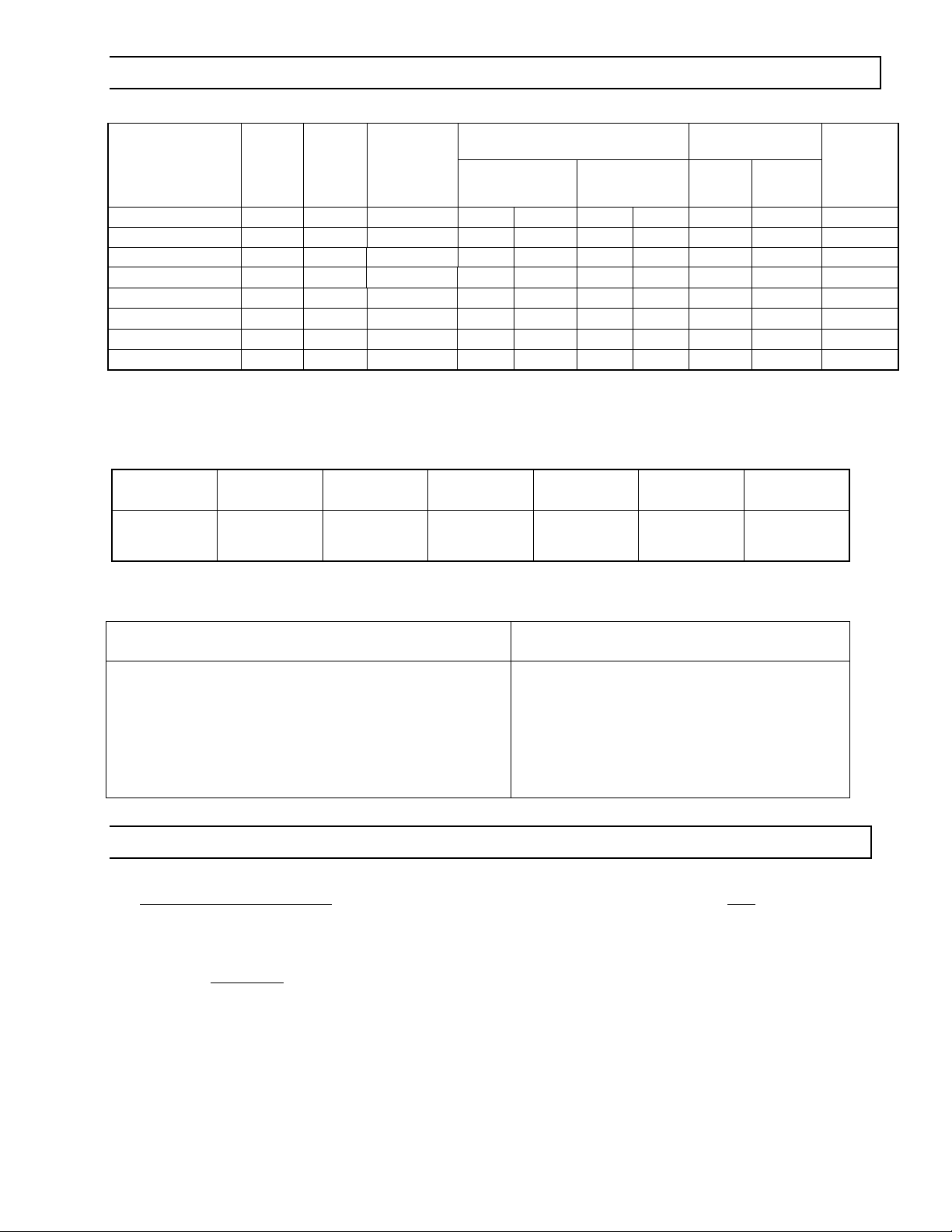
A. BASIC FLUE VENTING — Venting must comply with the latest edition of the National Fuel Gas Code (ANSI
Z223.1-latest edition) or the authority having jurisdiction. Other venting references are in the equipment volume of
the ASHRAE Handbook.
Model Heat
exchanger
Maximum vent length ft.
(4” diameter)
length ft
Maximum Fresh air
intake length ft (4”
diameter)
Max. combination of
fresh air and vent ft. (4”
diameter)
PTS/U 40/25 20 45 50 75
PTS/U 50/30 20 45 50 75
PTS/U 50/30 30 35 40 65
PTS/U 75/50 20 45 50 75
PTS/U 75/50 30 35 40 65
PTS/U 100/65 30 45 50 75
PTS/U 100/65 40 35 40 65
PTS/U 125/80 30 60 50 75
PTS/U 125/80 40 50 40 65
PTS/U 125/80 50 40 30 55
PTS/U 150/100 40 60 50 75
PTS/U 150/100 50 50 40 65
PTS/U 150/100 60 40 30 55
PTS/U 175/110 50 60 50 75
PTS/U 175/110
PTS/U 175/110
PTS/U 175/110
60 50 40 65
70 40 30 55
50 60 40 65
PTS/U 200/125 60 50 30 55
PTS/U 200/125
70 40 30 45
Vent lengths shown in the table are for horizontal and vertical venting. If a longer length of vertical or horizontal
venting is required contact the manufacturer for assistance with vent sizing.
SINGLE HEATER VENTING (VERTICAL THROUGH THE ROOF)
1. When venting the heater to outside of building through a roof, use single-wall metal pipe. This is to be
constructed of galvanized sheet metal or other approved noncombustible corrosion-resistant material as
allowed by state or local codes.
2. A vent passing through a combustible roof shall extend through an approved clearance roof thimble.
Double-wall, Type B vent must be used for the portion of the vent system which passes through the roof. An
approved vent cap (Leslie “VersaCap”-Type B or equal) must be attached to end of the flue.
3. The maximum equivalent length of vent pipe should be carefully observed. A safety switch in the heater is
designed to shut the heater off before excessive flue restriction causes bad combustion. Refer to the Vent
Sizing Table for maximum vent lengths and vent pipe diameter.
4. Joints between sections of piping shall be fastened by sheet metal screws or other approved means and
should be sealed to prevent leakage of flue gas into building. Aluminum or Teflon tape suitable for 550ºF
(3M Company tapes 433 or 363) or silicone sealant is recommended.
5. All portions of the vent pipe shall be supported to prevent from sagging (6’ spacing is recommended).
6. When the vent pipe passes through areas where the ambient temperature is likely to induce condensation of
Form #43343530
–34– JJuly 08
Page 36

the flue gases, the vent pipe should be insulated and a condensation drain should be provided.
7. Minimum clearance for single-wall flue pipe to combustible material shall be 6 inches. This may be reduced
when the combustible material is protected as specified in the National Fuel Gas Code or the authority
having jurisdiction.
8. Single-wall metal pipe shall not originate in any unoccupied attic or concealed space and shall not pass
through any attic, inside wall or concealed space, or through any floor. For the installation of a single-wall
metal pipe through an exterior combustible wall, refer to latest edition of the National Fuel Gas Code or the
authority having jurisdiction.
9. A venting system shall terminate at least 3 ft. above any forced air inlet located within 10 ft.
2 ft (77cm) minimum
(when no wall or
parapet exists)
or less
Vent
2 ft (77cm)
minimum
Wall or
Parapet
4 Vent Pipe
(vertical position)
#10 Self-Drill
Screws
(typical)
Flue Adapter
Collar
4 Vent Elbow
Vent Cap (Leslie
VersaCap Type B)
Flashing
2 (5cm)
Clearance
Thimble
Seal Joint
and Annular
Space
10 ft (305cm)
4 Diameter
SINGLE HEATER VENTING (HORIZONTAL THROUGH SIDEWALL)
When venting the heater horizontally through a combustible outside sidewall, the same requirements listed
previously for venting Vertical Through The Roof apply except as follows:
1. A vent passing through a combustible wall must pass through an approved clearance thimble (Air-Jet #4VT
or Ameri-Vent #4EWT or other thimbles that are listed by a nationally recognized testing agency.
2. An approved vent cap (Breidert-Type L or equal) must be attached to the end of the vent pipe.
NOTE
: To minimize problems associated with condensation in long horizontal runs, vent pipe can be insulated.
3. Use the following correction factors to obtain the equivalent length when elbows are used:
c. Subtract 10 ft. for each elbow beyond 15 ft. from the heater.
d. Subtract 15 ft. for each elbow within 15 ft. of the heater.
4. Limit to (2) 90º elbows in the vent system.
5. When venting through a sidewall, the horizontal vent pipe shall fall not less than 1/2 inch per 20 feet from
the start of the vent system to the vent terminal. All portions of the vent pipe shall be supported to prevent
sagging. (6’ spacing is recommended)
6. A minimum clearance of 6 inches must be maintained between the outside wall and vent cap.
7. The horizontal venting system shall not terminate:
a. Less than 4 ft. (1.2m) below, 4 ft. (1.2m) horizontally from or 1 ft. (30cm) above any door, operable
window or gravity air inlet into any building. The bottom of the vent terminal shall be located at least 7
ft. (2.1m) above grade or above snow accumulation level as determined by local codes.
b. Less than 3 ft. (0.9m) from a combustion air inlet.
c. Less than 3 ft. (0.9m) from any other building opening or any gas service regulator.
d. Less than 7 ft. (2.1m) above public walkways.
e. Directly over areas where condensate or vapor could create a nuisance or hazard or be harmful to the
operation of gas utility meters, regulators, relief valves, or other equipment. Building materials should
be protected from flue gases and condensate.
8. In regions of the country where prevailing winds are consistently higher than 40 mph, it may be necessary to
terminate the vent system above the roof level.
Form #43343530
July 08 –35–
Page 37

#10 Self-Drill
Screws
(typical)
4 Vent Pipe
(horizontal position)
6 (15cm)
minimum
2 (5cm)
Clearance
Thimble
Flue Adapter
Collar
1/2 (12mm) fall per 20 ft
(6m) toward vent terminal
Vent Cap
(Breidert or
equivalent Type L)
MULTIPLE HEATER VENTING (CONNECTIONS INTO A COMMON VENT OR MANIFOLD)
Requirements for venting of multiple heaters are the same as described for SINGLE HEATER VENTING except as
follows:
1. The common vent size and total vent height is normally determined by the number of heaters per common
vent, length of horizontal connector runs, and connector rise. Connector lengths should be as short as
possible and have a minimum 1/2 inch per 20 foot fall. Without regard to connector rise and total vent
height due to many possible venting configurations, the following should be observed:
a. Common vent pipe & vent connector diameter should be no less than that shown in the following Vent
Sizing Table.
b. The connector length should be no more than 75% of the vertical portion of vent above the connector.
c. Where possible, use a Y-connector to the common vent.
2. Material for connectors should be constructed of galvanized sheet metal or other approved noncombustible
corrosion resistant material as allowed by state or local codes. All common vent pipe should be double wall,
Type B vent.
3. Avoid unnecessary bends. Limit to two (2) 90º elbows.
4. The entire length of vent connector shall be readily accessible for inspection, cleaning and replacement.
5. Groups of heaters with a common vent must be controlled by a common thermostat.
Multiple Heater Vertical venting arrangement.
Vent Cap (Leslie
VersaCap Type B)
2 ft (77cm) minimum
(when no wall or
parapet exists)
Wall or
Parapet
2 ft (77cm)
minimum
Flue Collar
adaptor
To ta l
Vent
Height
Plan View
Flashing
2 (5cm)
Clearance
Thimble
Seal Joint
and Annular
Space
10 ft (305cm)
or less
See multiple
vent size table
for diameter
4 Diameter
single wall Vent
Connections to the common vent
must be arranged to avoid direct
opposition of exhaust products.
Form #43343530
–36– JJuly 08
Page 38

Multiple Heater Horizontal venting arrangement.
Vent Cap
6 (15cm)
minimum
(Breidert or
equivalent Type L)
COMMON VENTING OF MULTIPLE HEATERS IN CONFINED SPACES IS
PROHIBITED. If any heater connected to a common vent system for
multiple heaters is found inoperative, the heater should be
disconnected from the vent system and its entrance into the vent
system capped.
Plan View
6 (15cm)
minimum
1/2 (12mm) fall per 20 ft
(6m) toward vent terminal
4 Diameter
single wall Vent
2 (5cm)
Clearance
Thimble
Swept Tee
See multiple
vent size table
for diameter
Flue Collar
adaptor
1/2 (12mm) fall per 20 ft
(6m) toward vent terminal
4 Diameter
single wall Vent
Swept Y
2 (5cm)
Clearance
Thimble
See multiple
vent size table
for diameter
Flue Collar
adaptor
VENT SIZING TABLE — Multiple Heater Venting
Number of Heaters
Horizontal and vertical Vertical Only
1 2 3 4
PTS/U 40/25 4” 4” 4” 4”
PTS/U 50/30 4” 4” 4” 5”
PTS/U 75/50 4” 4” 5” 6”
PTS/U 100/65 4” 5” 6” 6”
PTS/U 125/80 4” 5” 6” 7”
PTS/U 150/100 4” 6” 7” 7”
PTS/U 175/110 4” 6” 7” 8”
PTS/U 200/125 4” 6” 7” 8”
(If a size is not available use the next larger size.)
COMMON VENT DIAMETER
B. INDIRECT VENTING (UNVENTED HEATERS) — This heater requires ventilation in the building to dilute the
products of combustion and provide fresh air for efficient combustion. Where unvented heaters are used, gravity
or mechanical means shall be provided to supply and exhaust at least 4 CFM per 1,000 Btu/hr input of installed
heaters. Exhaust vents must be located at the highest point above and in the vicinity of the heaters, and the inlet
vents must be located below the level of the heaters. An exhaust hood (Part #42924000) must be placed on the
flue adapter collar located on the end of the last body section when used unvented and must be mounted only in
an downward position as shown.
4 (10cm) Exhaust hood PN 42924000
(point down away from ceiling)
#10 Self-Drill
Screws
Flue Adapter
Collar
(typical)
Form #43343530
July 08 –37–
Page 39

17.0) AIR FOR COMBUSTION
If indoor combustion air is to be supplied for a tightly enclosed area, one square inch of free area opening shall be
provided below the heater for each 1,000 Btu/hr of heater input. Adequate clearances around the air inlet screen
must be maintained a t all times. In larger ope n area s of buildings, infiltration normally is adequate to provide air for
combustion.
17.1) DIRECT OUTSIDE AIR FOR COMBUSTION
Outside combustion air should be supplied directly to the heater when the building is subject to negative pressure, or
when contaminants or high humidity are present in the building air. These contaminants include paints, solvents,
corrosive vapors or any other foreign particles that may cause damage to the heater or result in poor combustion.
Outside combustion air can be brought directly to the heater by a 4” diameter duct less than 50 ft. long or equivalent
(see table in Section 16). This is attached to the 4” diameter starting collar (supplied with heater). The starting collar
is fitted to the rear of the burner box cabinet as shown below. An approved vent cap must be placed directly on the
end of the outside combustion air inlet pipe. The combustion air inlet should be not less than 3 ft. (0.9m), either
vertically or horizontally, from the flue vent termination. The air intake terminal must be located not less than 1 ft.
(30cm) above grade. It is good installation practice to supply combustion air from the same pressure zone as the
vent outlet. Avoid bringing combustion air to the heater from an attic space. There is no guarantee that adequate
combustion air will be supplied.
If the heater is installed less than 2 ft. from the ceiling, a combustion air inlet kit PN 44129510 must be provided to
allow for expansion/contraction of straight tube heaters (PTS series).
In colder climates, where necessary, insulate the outside combustion air duct. In high humidity applications, the
burner box should be sealed with silicone sealer.
Vertical
Through the roof
Combustion Air Cap
(Leslie VersaCap
Type B)
3 ft. (91cm)
Minimum
Horizontal
Through Sidewall
6 (15cm)
Minimum
Flashing
4 Diameter
Single-Wall Pipe
1/4 (6mm)
per ft. slope downwards
towards vent terminal
4 Spring
Tension Clamp (2 each)
(Part No. 30676040)
4 Starting Collar
Burner Box
(side view)
4 Flexible Air Inlet Hose
2 Ft. Long
(Part No. 30675020)
Form #43343530
–38– JJuly 08
Page 40

In multiple heater applications, the combustion air intake may be ducted individually or common ducted in the same
configuration as shown for venting in Section 16.0. For combustion air intake duct sizing, please refer to the Vent
Sizing Table and use the diameter indicated, based on the number of heaters per duct.
SIDE VIEW
(straight configuration)
Flue vent termination
must be 1 ft. (30 cm)
higher than combustion
Combustion
Air Intake
air inlet cap.
18.0) LIGHTING AND SHUTDOWN INSTRUCTIONS
Never operate the heater with the access panel open or removed.
The access panels must be closed tightly with all the necessary
screws during operation.
Failure to do so may result in death, serious injury or property
damage.
The access doors on either side of the burner must
be securely fastened before operating the heater.
DANGER
FIRE HAZARD
Never operate the heater with the
access panel open or removed.
This access panel must be closed
tightly with all the necessary screws
during operation.
Failure to do so may result in death,
serious injury or property damage
43269050 Rev. A 03/08
SIDE VIEW
1) Turn on the gas and electrical supply. Rotate the gas valve knob counter-clockwise to the “ON” position.
2) Set the thermostat to call for heat (high fire). The blower motor will energize.
3) Ignition should occur after the 15-second pre-purge.
4) If the burner fails to light, or flame is not detected during the first trial for ignition (a period of approximately 15
seconds) the gas valve is de-energized and the control goes through an inter purge delay of approximately 60
seconds before another ignition attempt. The control will attempt two additional ignition trials before going into
lockout, and the valve relay will be de-energized immediately. The blower will be turned off following a post-purge
period of approximately 30 seconds.
5) If the heater does not light, manually reset the thermostat or shut off power completely for 5 minutes before
attempting to relight.
6) CAUTION:
The heater must be grounded. Poor grounding will give nuisance lockouts, particularly during
momentary power interruptions.
7) When the thermostat is satisfied with high heat, the heater will switch to low fire.
8) To shut off the heater, rotate the gas valve knob clockwise to the “OFF” position and turn off the gas at the
manual gas shut off valve supplying the heater and disconnect the electrical supply.
NOTE
: THE LIGHTING AND SHUTDOWN INSTRUCTIONS ARE ALSO SHOWN ON THE PERMANENT NAMEPLATE LABEL
ATTACHED TO THE HEATER.
Form #43343530
July 08 –39–
Page 41

19.0) SEQUENCE OF OPERATION
The chart below shows the sequence of operation for the normal operating cycle of the PTS/PTU when connected
to a permanent 120V power supply and the heater is turned on and off by a remote 24V thermostat. (Electrical
connection diagram B).
Thermostat low fire
Thermostat high fire
Blower
Air switch
Red power light
Ignition
Gas valve low fire
Gas valve low fire
Gas valve high fire
Flame sensing
Amber valve light - low fire
Amber valve light - high fire
Call for heat, Thermostat on
15 secs pre-purge
15 secs trial for ignition
Normal high fire operation
flame sensing
Thermostat - high fire off
Thermostat (turn off)
30 secs post-purge
Heater OFF
T0 T1 T2 T3 T4 T5 T8
Function ON Function OFF
T6
T7
If the flame is not sensed during sequence T3 then the burner will automatically begin re-ignition sequence T2. The
ignition sequence will be repeated three times with a 60 second inter-purge. If the flame is not re-established the
heater will go to lockout.
Form #43343530
–40– JJuly 08
Page 42

20.0) BURNER COMPONENT LOCATIONS
2
30
9
7
33
6
32
31
12
8
Note: This panel
must remain closed
for burner operation.
17
15
14
16
13
Legend
1 Cabinet Assembly
2 Access Panel - Top
3 Access Panel - Hinged (2 ea)
4 Access Panel - LH Burner
5 Access Panel - RH Burner
6 Air Inlet Screen
7 Gas Inlet Connection - 1/2NPT
8 Power Supply Cord - 120V
9 Burner Sight Glass
10 Indicator Light - Amber (Gas Valve)
11 Indicator Light - Red (Air Switch)
12 Tube Flange Connection
13 Main Burner
14 Flame Screen (200m/BTU units only)
15 Electrode
16 Flame Sensor
17 Main Burner Orifice
18 Air Restrictor Plate
18
4
3
10
22
34
23
11
Note: This panel
must remain closed
for burner operation.
3
5
24
21
26
35
25
19
:
20
28
27
19 Gas Control Valve
20 Ignition Module
21 Ignition Cable
22 Blower Assembly
23 Transformer - 120/24 VAC
24 Terminal Block/Fishpaper Shield
25 Air Switch
26 Air Sensing Tube (P1+)
27 Air Sensing Tube (P2-)
28 Manifold Pipe
29 Manifold Support Bracket/Clamp
30 Terminal Block (24V thermostat)
31 Terminal Block (TISS connection)
32 Starting Collar
33 Valve Holder Plate
34 Fuseholder/Fuse (2 amp)
35 Combustion Air Plate
1
29
Form #43343530
July 08 –41–
Page 43

21.0) CLEANING AND MAINTENANCE
ELECTRIC SHOCK & EXPLOSION HAZARD
Disconnect electrical power and gas supply before
servicing.
Failure to do so may result in death or serious injury.
This heater must be cleaned and serviced annually by a qualified contractor before the start of each heating season
and at any time excessive accumulation of dust and dirt is observed. Maximum heating efficiency and clean
combustion will be maintained by keeping the heater clean.
The contractor shall check the following during periodic maintenance.
• Clearances to combustibles:
objects, liquids or vapors near the heater. See also Section 4.
• Reflectors:
output).
• Heat exchanger tubes:
signs of fatigue.
• Combustion air intake:
flashlight to make sure no foreign material has collected in the tubes and that there is no obstruction around the
air intake openings. Clean any foreign materials. Inspect any joints to make sure they are completely sealed. See
also Section 17.
• Venting System:
has collected in the pipes. Check the external vent cap and make sure that there is no obstruction around the
exhaust openings. Clean any foreign materials. Inspect any joints to make sure they are completely sealed. See
also Section 16.
• Gas lines:
damage, fatigue or corrosion. If there are any signs of damage to the gas connection or leaks found in the gas
piping, immediately stop using the heater until the gas pipe and connections have been repaired or replaced.
Check that the gas lines are not bearing the weight of the heater. See also Section 13.
• Burner Box:
Check that the burner box is level, use the turnbuckle on the burner suspension eyebolt to adjust the level of the
burner. See also Section 9.
• Burner sight glass:
door. If there any signs of distortion, the sight glass must be replaced. See section 20 for sight glass location.
• Blower wheel and housing:
air. See section 20 for blower location.
• Electrode condition: Visually check that the electrode gap is maintained at 1/8” and that the tips of the flame
sensor and spark electrode are free from deposits. Clean off any deposits. Check that the electrode ceramic is
free from cracks. See Section 23.1
• Suspension system:
hanging securely, look for any evidence where the heater may have been hit accidentally and tighten any loose
hanging points. Check that S hooks are closed. Check that there is no evidence of wear on the chain at the
connection to the heater and at the ceiling.
• Tube Integrity Safety System:
Adjust tension if necessary. See section 12.1
• Main Burner and Orifice:
Section 23.1
Reflectors should be kept clean, at a minimum blow off the reflectors. (Dirty reflectors will reduce heat
Disconnect vent pipe and inspect internally using a flashlight to make sure no foreign material
Make sure that the gas lines are not leaking. Check the gas connection to the heater for any signs of
In order to extend the longevity of the heater, the heat exchanger tube and the burner must be level.
Check that the burner sight glass is clean and that the glass is sealed against the housing
Check that the suspension system is holding the heater level. Make sure that the heater is
Check that clearances are being maintained. Make sure there are no flammable
Inspect the heat exchanger tubes to make sure they are not cracked, sagging or showing
Disconnect combustion air intake from the burner box and inspect internally using a
Check that the blower wheel spins freely, blow out any dust or dirt with compressed
Check that the tension of the tube integrity safety system is maintained at 11”.
Check the Main burner and orifice, remove any dirt or debris including spider webs. See
Form #43343530
–42– JJuly 08
Page 44

22.0) TROUBLESHOOTING GUIDE
Replace heat
exchanger tube,
reflector and TISS.
Yes
No
The TISS has broken
continuity. Check the
first tube and reflector
Check TISS wire for
a break if it is close to
the terminal repair.
Otherwise replace
TISS wire.
is there a hole?
No
Repair or replace
jumper check all wire
terminals.
No
Replace air switch.
Yes
No
Check the probes and
hoses to the air switch
are they clear and
Yes
Is the black tap on the
air switch connected
to the upper probe?
Yes
Does the LED on the
ignition module flash
once?
Yes
Clean out hoses and
unobstructed?
No
Switch hoses on the
No
Check NO terminal of
probes.
pressure taps.
the air switch
connection. Replace
if fuse carrier is tight
Check terminals for
red light.
Is there 24V between
No
No
transformer.
Is there 24V on the
Is there 24V between
Is the LED on the
and the fuse has no
continuity, replace the
fuse.
continuity at
transformer. If they
are good, replace
Yes
both terminals of the
TISS and ground?
Yes
other side of the fuse
carrier?
Yes
the inlet to the fuse
carrier and the
No
ignition module
steady ON?
No
ground?
Is there 24V between
both terminals of the
Is 120V at the terminal
block in the blower?
Check that red wire is
connected to TH from
Yes
Replace ignition
module.
No
thermostat connection
and ground?
Does the system have
a 24V individual
thermostat?
Yes
Yes
Replace ignition
modules.
No
air switch terminal C.
Repair connection.
Remove jumper, air
switch must be open
circuit first for blower
Yes
Yes
to operate.
Repair or replace
thermostat. Check
external wiring.
No
Are air switch
terminals jumpered?
Yes
No
Is the orange wire
from PSW connected
to the NO terminal of
the air switch?
No
Replace amber light.
Air switch is stuck in
the closed position.
Replace air switch.
Move orange wire to
NO terminal. Restart
troubleshooting.
Are the black wires
Are the blue wires
Restart
troubleshooting.
Yes
No
to the amber light
securely on the gas
valve terminals?
Yes
No
secure in the
terminals and firmly
on the ignition
module terminals?
Yes
Repair connection.
Restart
troubleshooting.
Repair connection.
Restart
troubleshooting.
No
24V between V1 and
V2 ignition module
terminals?
Replace ignition
No
Yes
steady ON?
No
Replace ignition
module.
module.
Yes
Troubleshooting
Does the blower
come on?
No
Turn on line voltage
and adjust thermostat
to the highest setting.
Does the red
monitoring light come
on?
Check line voltage
circuit. Repair fault.
No
No
Is 120V at the terminal
block in the blower?
Check terminals for
continuity and repair.
No
Yes
Is there 120V
between ground and
the L1 terminal on the
module?
Yes
During start up, is
there 120V between
ground and the IND
terminal on the
Yes
module?
Remove any
obstructions. Repeat
start up. If motor will
not run. replace
motor.
No
Yes
Disconnect the power
and check the blower
wheel. Does it turn
freely?
Yes
Does the LED on the
ignition module flash
once?
Yes
Replace motor.
Is the knob on the gas
valve turned to the
ON position?
No
Yes
Does the blower stay
on?
Move black light wire
to NO terminal of the
air switch. Restart the
troubleshooting.
No
Turn on the gas
valve?
After 15 seconds
post purge is there
Is the LED on the
ignition module
Yes
Does the low fire
amber light come on?
Form #43343530
July 08 –43–
continued on the next
page.
Page 45

Contact factory for
assistance.
Yes
No
Check flame sense
wire does it have
continuity?
Yes
Replace flame sense
wire.
No
Replace amber light.
Restart
troubleshooting.
Yes
No
Are the black wires
to the amber light
securely on the gas
valve terminals?
Repair connection.
Yes
No
Is there 24V at the HI
terminal on the gas
valve?
Yes
Check terminal
connections to the
gas valve, are they
Yes
Is the there 24V
between the
thermostat terminal
No
Repair terminal
No
tight?
Repair terminal
block high fire contact
and ground (yellow
wire)?
Restart
troubleshooting.
connections. Restart
troubleshooting.
connections.
Check external
thermostat wiring and
thermostat set point.
Yes
No
Remove red wire
from the Low fire
terminal, is there 24V
at the center C
No
terminal?
Check the red wires
C should be
connected to the TISS
and LO connected to
W (TH) module
terminal.
See next page for
troubleshooting
sequence.
No
Yes
Through the
inspection window is
there a flame visible
during start up?
Yes
No
Is the knob on the gas
valve turned to the
ON position?
No
Replace ignition
module.
Yes
No
Check the micro
Amps at the FC-FC+
terminals of the
module is it greater
than 0.7µA with flame.
Yes
No
Is the heater properly
grounded?
Yes
No
Does LED on the
ignition module flash
three times?
Turn on the gas
valve?
Remove and inspect
flame sense
electrode. Is it clean
and the ceramic
intact?
Repair or replace
Yes
No
Check the terminal on
the flame sense
electrode, is it tight?
Correct grounding
problem.
Replace ignition
module.
Adjust terminal
flame sense
electrode.
connection. Restart
troubleshooting.
Replace amber light.
Restart
troubleshooting.
Yes
No
Are the black wires
to the amber light
securely on the gas
valve terminals?
Repair connection.
Yes
No
Is there 24V at the HI
terminal on the gas
valve?
Yes
Check terminal
connections, is the
yellow wire
Yes
Is there 24V between
the thermostat
terminal block low fire
No
Repair terminal
No
connected to the high
fire terminal?
Switch terminal
No
contact and ground?
Check external
Restart
troubleshooting.
connections. Restart
troubleshooting.
connections. Red wire
LO should be
connected to ignition
module W (TH)
terminal.
thermostat wiring and
thermostat set point.
Does the high fire
amber light come on?
Yes
Does the low fire
amber light stay on
past 10 seconds?
Yes
With the thermostat
set to low fire only
does the low fire
amber light come on
after 15 seconds?
Yes
Troubleshooting
continued on the next
page.
Form #43343530
–44– JJuly 08
Page 46

Yes
Replace air switch
No
No
Replace blower
assembly.
No
Repair or replace
jumper check all wire
terminals.
No
Check the pressure
across the air switch
during hot running is
it higher than the
minimum required?
Yes
Replace air plate.
Yes
Remove blower does
the wheel turn freely?
Yes
Check vent and fresh
air lengths, are they
within the maximum
Yes
Check turbulator, are
the correct number of
lengths installed?
Check air plate
permissible?
No
Change number of
No
stamped part
numbers. Are they
correct?
turbulators.
Yes
Contact factory for
assistance.
Replace flame sense
wire.
Contact factory for
assistance.
Yes
Contact factory for
assistance.
Yes
No
Check flame sense
wire does it have
continuity?
Yes
Remove and inspect
flame sense
electrode. Is it clean
and the ceramic
intact?
Yes
No
Tighten terminals.
Restart
troubleshooting.
No
Repair or replace
flame sense
electrode.
No
Remove and re-insert
electrode. If it still
sparks to the side.
Replace electrode.
Yes
Is there are spark to
the side of the burner
cup?
Yes
No
Are the terminals tight
on the electrode and
the ignition module?
Replace electrode.
Carefully bend the
terminal away from
the burner casting.
Restart
Yes
No
Check the terminal at
the electrode does it
arc to the burner
casting?
No
Turn off gas and
check for spark. Is
there a spark to the
throat of the burner
No
Yes
Remove spark
electrode and
inspect, is the
ceramic cracked or
Yes
No
troubleshooting.
No
Replace flame sense
wire ignition cable. If
Yes
Check nameplate are
cup?
loose?
the gas type, orifice
Contact factory for
assistance.
Yes
problems persist
contact factory for
assistance.
Yes
and airplates correct
for the stated burner
specification?
Contact factory for
assistance.
No
No
Clean blower wheel.
Restart
troubleshooting.
Remove blower is the
Check the air intake
Does LED on the
wheel free from dirt
and dust?
No
Yes
Remove blockage.
and vent are there
any blockages?
Yes
ignition module flash
once?
No
Restart
Contact factory for
assistance.
No
Does LED on the
ignition module flash
troubleshooting.
Check gas pipe
No
Yes
three times?
Check the gas supply
Check the micro
Amps at the FC-FC+
Is the heater properly
grounded?
Remove burner
sizing, regulators and
system supply gas
pressures.
No
pressure with all the
heaters on. Does it
stay above the
minimum required?
casting and check
Yes
After an initial step
opening is the
terminals of the
module is it greater
than 0.7µA with flame.
Check the terminal on
the flame sense
electrode, is it tight?
Yes
No
Correct grounding
problem.
Yes
No
Remove blockage.
Restart
the orifice. Is it clean
and free from
blockage?
Yes
manifold gas
pressure correct?
troubleshooting.
No
Adjust manifold
pressure. Restart
troubleshooting.
Adjust terminal
connection. Restart
troubleshooting.
Yes
Adjust spark gap
carefully. Restart
troubleshooting.
Yes
Replace gas valve.
Troubleshooting
continued from
previous page
Check electrode
spark gap. Is it 1/8?
No
Check the manifold
gas pressure during
start up. Is it zero
inches w.c?
Yes
No
Check the inlet
pressure to the gas
valve. Is it between
the minimum and
maximum for the gas
pressure?
No
Yes
Is the LED on the
ignition module
steady on?
Yes
No
Remove burner and
check the orifice. Is it
clean and free from
blockage?
Yes
No
After an initial step
opening is the
manifold gas pressure
correct?
Adjust manifold gas
pressure.
Replace ignition
module.
Remove blockage.
Restart
troubleshooting.
Adjust manifold
pressure. Restart
troubleshooting.
Purge the gas supply
Does the amber light
stay on until the
thermostat turns off?
Troubleshoot Ends
Has all the air been
purged from the gas
supply lines?
lines.
Form #43343530
July 08 –45–
Page 47

23.0) REPLACING PARTS
ELECTRIC SHOCK & EXPLOSION HAZARD
Disconnect electrical power and gas supply before
servicing.
Failure to do so may result in death or serious injury.
Only use genuine Space-Ray replacement parts. Parts are available from the factory for replacement by a licensed
person. Refer to the Replacement Parts Guide in Section 25 for all replacement parts.
23.1) REMOVAL OF MAIN BURNER AND ELECTRODES
The main burner can be inspected without removing the burner housing from the heat exchanger tube.
1
3
2
5
1/8 spark gap
4
7
8
6
1. Disconnect electrical supply and Remove cover 1.
2. Remove screw securing burner casting to the gas manifold.
3. Disconnect Spark lead and sensing wire.
4. Pull burner forward from the gas manifold and then out through the side of the box as shown.
5. Check that the spark gap is 1/8” between the electrode and the burner casting as shown. Spark electrode
should be clean and free from debris.
6. Flame sensor should be clean and free from debris.
7. Check ceramic on the spark electrode, for replacement into the box the spark electrode is the ¼” terminal
which connects to the spark lead.
8. Check ceramic on flame sense electrode, for replacement into the box the flame sense electrode is the
3/16” terminal which connects to the violet wire. (in some models the terminal is ¼” painted violet)
Form #43343530
–46– JJuly 08
Page 48

23.2) REMOVAL OF GAS VALVE AND MANIFOLD ASSEMBLY
Loosen screws from
Step 1
Remove side
access panel.
Step 2
manifold clamp and
burner assembly.
Open hinged access
panel and disconnect
Step 3
wires from gas valve.
23.3) AIR SWITCH PRESSURE CHECK
P1
+
Connector
Tees
-
+
0.65 WC
P1
+
P2
-
Digital or Inclined
Water Manometer
scale 0-2w.c.
Air
Switch
P2
-
Temporary 1/4 ID Silicone /
plastic tubing for pressure
test.
Step 4
Remove (6) screws from
end panel. Rotate gas valve
and manifold assembly
slightly counter-clockwise
and slide out from housing.
Common C
Normally
open NO
1. Open hinged access panel.
2. Add tubing to connect the air switch tubing P1 + and P2 - with the connector tees and the probes P1+ and P2+.
Form #43343530
July 08 –47–
Page 49

3. Connect plastic tubing of a digital or inclined water manometer with a 0-2” scale onto the connector tees.
4. Turn heater on and wait until blower motor is activated.
5. Observe air pressure from manometer. This should be higher than the set point indicated below for correct
operation.
Model
Operating Pressure
Model
Operating Pressure
PTS/U 40/25 0.98” W.C. Hot PTS/U 125/80 0.39” W.C. Hot
PTS/U 50/30 0.98” W.C. Hot PTS/U 150/100 0.39” W.C. Hot
PTS/U 75/50 0.70” W.C. Hot PTS/U 175/110 0.39” W.C. Hot
PTS/U 100/65 0.70” W.C. Hot PTS/U 200/125 0.39” W.C. Hot
All pressures are with the heater in operation for at least 15 minutes.
23.4) IGNITION SYSTEM CHECKS
TO CHECK FLAME SENSOR CIRCUIT.
Flame current is the current which passes through the flame from the sensor to ground. The minimum flame
current necessary to keep the system from lockout is 0.7 microamps.
a) Turn off heater at thermostat.
b) Connect a me ter (dc mi cro amm ete r sca le) in seri es wi th the ground le ad as sho wn in the diagra m. Con nect the
meter as follows:
Connect the black (negative) meter lead to the electronic control FC- terminal.
Connect the red (positive) meter lead to the electronic control FC+ terminal.
c) Restart the system and read the meter. The flame sensor current must be steady and measure at least 0.7
microamps.
d) If the meter reads less than the minimum or if reading is unsteady:
Make sure burner flame is capable of providing a good rectification signal.
Make sure fasteners securing igniter/sensor are tightened to assure correct positions. DO NOT relocate
igniter/sensor.
Check for excessive (over 1000ºF) temperature at ceramic insulator on flame sensor. Excessive temperature
can cause short to ground. DO NOT relocate igniter/sensor.
Check for cracked ceramic insulator, which can cause short to ground, and replace sensor if necessary.
Make sure that electrical connections are clean and tight. Replace damaged wire.
e) If the meter reads below “0” on the scale, meter leads are reversed. Disconnect power and reconnect meter
leads for proper polarity.
f) Remove microammeter. Return system to normal operation.
IGNITION MODULE DIAGNOSTICS
Flame Fault
If at any time the main valve fails to close completely and maintains a flame, the full time flame sense circuit will
detect it and energize the combustion blower. Should the main valve later close completely removing the flame
signal, the combustion blower will power off following the post purge period.
Fault Conditions
MULTIPURPOSE METER
Error Mode LED Indication
Flame Sensor Current Check
Internal Control Failure Steady On
Air Flow Fault 1 Flash
Gas valve failure (stuck open) 2 Flashes
Ignition Lockout 3 Flashes
The LED located on the ignition module will flash ON
for ¼ second, then OFF for ¼ second during a fault
condition. The pause between fault codes is 3
seconds.
Form #43343530
–48– JJuly 08
S1
GND
V2
(R) 24VAC
L1
IND
NC
V1
P.SW
(W)TH
Ignition Module (Fenwal)
FC-
FC+
BLACK (-)
RED (+)
LED Display
USE
MICROAMP
SCALE
Page 50

24.0) INSTALLATION DATA
Date of Installation: # of Heaters in System:
Serial No.
N = Natural Gas
Model: PTS or PTU
L = Propane Gas
25.0 REPLACEMENT PARTS GUIDE – BURNER BOX
Item
No. Part No. Description Qty.
Fasteners
1 02295040 PHTCS #6-32 x 3/8" 3
1a 02266010 Speed Clips (for air inlet plate) 2
2 02261030 HHTCS #8-32 x 3/8" (green coated) 1
3 02242050 PHTCS #8-32 x 3/8" 5
4 02215020 HHMS #8-32 x 3/4" 2
5 02167010 Locknut 1/4-20 Keps 5
5a 02309000 Eyebolt 1/4-20 x 2” 1
6 02167040 Locknut #8-32 Keps 9
7 02212020 HWHSMS #8 x 1/2" “B” Point (typical all access panels) 45
8 02132020 Rivet 1/8" 14
Housing Components
9 44139990 Housing Assembly (welded) 1
9a 44140111 Valve Holder Plate 1
10 44140000 Access Panel (top) 1
11 44140040 Access Panel (hinged) 2
11a 02201070 Hinge 1-1/16” x 6” 2
12 44140058 Access Panel (LH burner end) –with sight glass- 1
13 44140090 Access Panel (RH burner end) 1
14 4414006x Combustion Air Plate (see size requirements in section 5.0) 1
Burner Components
15 42700500 Burner, Investment Casting - Machined 1
16 44146030 Manifold Support Bracket 1
17 44146040 Manifold Support Clamp 1
17a 44146050 Manifold Extension Bracket 1
18 30703000 Blower Assembly 1
19 30632500 Spark Module - Fenwal-24V #35-615935-197 1
20 30702010 Flame Sensor #PSE-GF24 1
21 30702020 Electrode #PSE-GF25 1
22 30281000 Terminal Block #EK-204 1
22a 30738030 Terminal Bushing (3 x ¼” tabs) 1
22b 30713000 Fuse Holder 1
22c 30202000 Fuse 1/4 x 1-1/4” (2 amp) 1
22d 30738020 Terminal Bushing (2 x ¼” tabs) 1
23 30279000 Transformer 120v-24V 20VA 1
24 02175020 Strain Relief #SR-6P3-4 (ignition cable) 1
25 02175060 Strain Relief #SR-2M-1 (flame sensor wire) 1
26 30514020 Grommet .250ID #739 (air sensing tube) 1
26a 30512020 Split Bushing #2871 (misc. wiring, ignition cable, sensor wire) 2
27 30700040 Grommet, Pipe Sealing 1/2" #63595K34 1
28 42447000 Sight Glass (1-5/8" square plexiglass) 1
Form #43343530
July 08 –49–
Page 51

29 42744079 Air Sensing Tube Asm. (straight) 1/4"od 1
30 42744069 Air Sensing Tube Asm. (90 deg bend) 1/4" 1
31 30635030 Cord Connector 1/2” #LPCG50 1
32 03988100 Plastic Vacuum Air Tube 10" (P2- to static pressure point) 1
33 03988100 Plastic Vacuum Air 10" (P1+ to total pressure point) 1
34 43563040 Supply Cord -Flat (SPT-1 18/3 x 72" long) 1
35 42709000 Shield, Terminal Block 1
36 42395010 Gasket, Blower 1
37 03946010 Sealing Strip 1/8" x 3/8" wide (access panels) -not shown- Ft.
38 42752250 Air Inlet Screen 1
38a 30504040 Starting Collar (combustion air inlet) 1
39 30701240 Ignition Cable - Female (2) 1/4" QC x 24"lg #PSE-GF23 -not shown- 1
40 44145060 Manifold Pipe – 6-1/4”lg 1
40a 03333140 Pipe Nipple – 4”lg 1
41 30333250 Gas Valve #VR8205Q-3819 (natural gas) 2-stage 1
41a 30333260 Gas Valve #VR8205Q-3827 (propane gas) 2-stage 1
42
42a
43 03259xxx Main Burner Orifice #7/16-27 (see size requirements in section 5.0) 1
44 42741150 Air Restrictor Plate 2-3/4” 1
45 44151010 Burner Screen Sub-Assembly (PTS/PTU 200 only) 1
46 42398030 Monitoring Light – Amber (gas valve operation) 2
47 42398150 Monitoring Light – Red (air switch operation) 1
48 30186250 Air Switch (set point @ .93”WC) PTS/PTU40 & 50 1
48a 30186260 Air Switch (set point @ .65”WC) PTS/PTU75 & 100 1
48b 30186270 Air Switch (set point @ .34”WC) PTS/PTU125,150,175 & 200 1
Labels/Manual
49 42848000 Label, Nameplate (Space-Ray) 1
50 42013000 Label, Logo (Space-Ray) (Not Shown) 1
51 43344070 Label, Clearances to Combustibles 1
52 42874030 Label, Wire Connection Diagram 1
53
54 42875000 Label, Warning (installation/configuration/chemical) 1
55 43269060 Label, 2 stage 24V Thermostat Connection 1
56 43269020 Label, TISS Connection 1
57 43269030 Label, Eyebolt Suspension Warning 1
58 43269040 Label, Gas Valve in “OFF” Position 1
59 43269050 Label, Burner Warning (access panel must remain closed) 1
60 43344110 Label, Flex Gas Connector 1
61 42785010 Label, Ladder Wiring Connection 1
62 42834000 Label, 120V Caution 1
63 42922030 Label, Sidewall Venting 1
64 43343530 Installation & Operation Manual (Not Shown) 1
Tube Integrity Safety Switch (TISS) Components
65 44175000 Retainer clamp 1
66 30519020 Spring 1
67 30736000 Thimble 1
68 44176010 TISS replacement assembly 1
Form #43343530
–50– JJuly 08
Page 52

9a
35
7
23
38a
5, 5a
38
22a
22
3
61
Red
Light
6
120V
Transformer
24V
Amber
TISS
Light
Thermostat
MV MV
Motor
Gas
Valve
Air
Switch
Flame
Sensor
S1
L1
HV
V2
V1
NC
IND
Igniter
GND
P.SW
(W)TH
24VAC
Ignition Module
SCHEMATIC WIRING DIAGRAM
42785020 03/08
24
25
26a
7
27
31
1
43
2
3
40
46
47
48
7
17a
40a
41, 41a
30
29
36
22d
26
18
1a
CONNECTION WIRING DIAGRAM
Schéma de circuit de connexion
(R) 24VAC
Ignition Module (Fenwal)
Bloc d'allumage
FACTORY WIRING
Circuit d'origine
FIELD WIRING
Connexions client
Optional Low
TISS
Red
Terminal Block
Voltage (24V)
(Tube Integrity
Light
Plaque à
Thermostat
Safety Switch)
bornes
Remove jumper wire.
Remove jumper wire.
Blue
Blue
GROUND
L1 (hot) 120V
L2 NEUTRAL
Terminal
Air Switch
Block
Blue
pressostat
(jumper)
Red
Draft Inducer
(W)TH
Gas Valve
Fuse 2A
Motor
Red
Robinet à gaz
P.SW
Fusible
Moteur
d'amorce
V1
Orange
d'aspiration
Amber
NC
Light
Black
IND
Black
L1
Green
Blue
V2
Orange
Green
GND
Electrode
Violet
S1
Gap 1/8
HV
High Voltage Cable
Haute tension
Écartement
If any of the original wire as supplied with the
d'électrode
appliance must be replaced. It must be
3,2Êmm
replaced with wiring material having a
temperature rating of at least 105oC. (18
Violet
AWG. - UL / CSA 600V Type TEW)
Flame Sensor
MONITORING LIGHTS
When connecting the supply circuit to the
Lampes témoins
heater, wiring material having a minimum size
of 14 AWG and a temperature rating of at
least 90oC shall be used.
52
Blue
(jumper)
Blue
Terminal Block
Transformer
Plaque à
Primary 120V
(line voltage)
bornes
THERMOSTAT
Secondary 24V
Black
L1 Black
L2 Black
White
(ribbed)
Transformateur
bobine primaire 120ÊV
bobine secondaire 24ÊV
Yellow
Green
Black
(ribbed)
CONTINUE TO
ADDITIONAL
HEATERS
Vers les autres
radiateurs
42874020 6/07
22c
1
22b
21
3
15
45
3
3
20
5
14
44
1a
10 22a
UN MUR LATÉRAL
SIDEWALL VENTING ONLY
Note: When venting a single
Nota: le conduit d'échappement
d'un radiateur simple traversant
heater horizontally through a
un mur combustible doit passer
combustible outside wall the
dans une gaine de 2 po (Air Jet
vent must pass through a 2
n° 4VT ou Ameri-vent n° 4EWT
clearance thimble (Air Jet No.
ou autre gaine normalisée par
4VT or Ameri-vent No 4EWT
un organisme d'essai reconnu
or other thimbles which are
à l'échelle nationale.
listed by nationally recognized
testing agency.
Poser un capuchon d'évent
(Breidert n° 4L ou équivalent)
Attach a vent cap (Breidert No.
4L or equivalent)
Longueur minimale équivalente
du tuyau d'échappement = 1,5m
(5pi)
Minimum equivalent length of
Longueur maximale équivalente
vent pipe = 5ft (1.5m)
du tuyau d'échappement = 15m
Maximum equivalent length of
(50pi)
vent pipe = 50ft (15m)
LIGHTING & SHUTDOWN INSTRUCTIONS
1. Turn on gas & electrical supply.
2. Set thermostat to call for heat.
Infrared Radiant Tube Heater
3. Ignition should occur after prepurge.
Radiateur à tuve rayonnant à infrarouge
4. If ignition fails, the unit will spark for approximately 21 seconds
& go into safety lockout. Turn thermostat (or power) off for 60
For indoor installation only
seconds to take out of lockout.
Installer à lintérieur seulement
5. If heater does not light, shut off gas completely for 5 minutes
Vented or Unvented
before attempting to relight.
Gas Fired products Inc. Charlotte, NC
6. To shut down the heater, turn off the gas & electrical supply.
ANSI Z83.20b / CSA 2.34b - 2003 Tel: 1800 438 4936 e-mail info@spaceray.com
INSTRUCTIONS DALLUMAGE ET DE FERMETURE
SERIAL NO.
MODEL NO.
1. mettre la valve a gaz et linterrupteur a ON.
2. Creer une demande de chauffage au thermostat.
No. de Modelè
No. de Série
3. Lallumage devrait se produire apres de prepurge.
ALTITUDE
CODE DATE
4. Si lallumage ne se fait pas, le controle dallumage continu de
produire des etincelles sur une periode de 21 sec. et ensuite
tomber en securite. Mettre le thermostat (ou le courant) en
INPUT Btu/Hr
GAS TYPE
position darret (OFF) pour une periode de 60 sec. a fin
dinterrompre le processus de securite.
Consommation Btu / Hr
Type de Gaz
5. Si lappareil ne sallume pas, fermez le gaz completement pour
SUPPLY PRESSURE
MAXIMUM
une period de 5 min. avant deffectuer une nouvelle tentative
MINIMUM
dallumage.
Pression de Sortie
6. Pour fermer lappareil, fermez le gaz et le courant electrique.
MANIFOLD PRESSURE
ORIFICE SIZE
Installation in:
1. Aircraft hangers must be in accordance with the standard for Aircraft Hangers.
Pression a lechappement
Dimensions bec Veilleuse
ANSI/NFPA 409 (latest edition).
2. Public garages must be in accordance with the standard for parking structures,
ELECTRICAL:
MAX ANGLE:
ANSI/NFPA 88a (latest edition), or with the standard for repair garages,
Max Angle
Electrique
ANSI/NFPA 88b (latest edition)
DANGER
FIRE HAZARD
Never operate the heater with the
access panel open or removed.
This access panel must be closed
tightly with all the necessary screws
during operation.
Failure to do so may result in death,
serious injury or property damage
12 8, 28 13
63
AÉRATION
WARNING
ELECTRIC SHOCK
HAZARD
Disconnect electrical supply
before servicing
Failure to follow these
instructions may result in
death, serious injury or
property damage.
THIS UNIT EQUIPPED WITH A
2 AMP IN LINE-FUSE FOR
OVERCURRENT PROTECTION
OF CONTROL CIRCUIT
42922030 Rev - 11/07
ATTENTION INSTALLER!
THE GAS CONTROL VALVE IS FACTORY
SET AT OFF POSITION. OPEN THIS
ACCESS PANEL TO TURN THE GAS
VALVE TO ON POSITION. BY THIS
ACTION YOU CERTIFY THAT ALL GAS
42848000 Rev. H 10/04
CONNECTIONS AND CHECKS COMPLY
WITH WRITTEN I & O INSTRUCTIONS
SHIPPED WITH THIS HEATER.
43269040 12/0743269040 12/0743269040 12/07
WARNING: Improper
AVERTISSEMENT: Une
installation, adjustment,
installation, un réglage, une
alteration, service or
modification, une réparation
maintenance can cause
ou un entretien incorrect peut
property damage, injury
entraîner des dommages
or death. Read the
matérials, des blessures ou
Installation, Operating
la mort. Lisez attentivement
and Maintenance
les instructions dinstallation,
Instruction thoroughly
de fonctionnement et
before servicing this
dentretien avant de procéder
equipment.
à linstallation ou à lentretien
de cet équipment.
This heater can be
installed in various
WARNING: This product
configurations as shown
contains a chemical known
in the heater layout
to the state of California to
section of the instructions
cause cancer.
43269050 Rev. A 03/08
WARNING: If not
installed, operated and
maintained in accordance
with the manufacturers
instructions, this product
could expose you to
substances in fuel or from
fuel combustion which can
cause death or serious
illness and which are
known to the State of
California to cause cancer,
birth defects or other
reproductive harm.
38a
BURNER SUSPENSION CHAIN
MUST BE USED TO SUPPORT
BURNER BOX. FAILURE TO USE
EYEBOLT SUSPENSION WILL VOID
MANUFACTURERS WARRANTY.
USE A TURNBUCKLE FOR LEVEL
ADJUSTMENT OF BURNER BOX.
43269030 12/07
2-Stage Thermostat
HI
C
LO
43269060 rev A
55
58
54
42875000 Rev. E 10/04
59 49 59 61
57
9
31
34
51 56
Combustible material must be located outside the clearance dimensions listed.
Failure to do so may result in death, serious injury or property damage
Models: PC(S,A)
Horizontal
Montage horizontal
Model No A B C D E F
B
75 27 6 60 30 48 12
(69cm) (15cm) (152cm) (76cm) (122cm) (30cm)
AA
100 66 6 88 40 66 20
(168cm) (15cm) (224cm) (102cm) (168cm) (51cm)
C
125 66 6 101 40 66 20
45 degrees
(168cm) (15cm) (257cm) (102cm) (168cm) (51cm)
Montage à 45°
B
150 84 6 106 48 84 24
(213cm (15cm) (269cm) (122cm) (213cm) (61cm)
E
F
Ceiling Clearance is 18 (46cm) when installed in an UNVENTED configuration. Ceiling
C
clearance is 18 (46cm) when the optional U-bend reflectors are not used.
D
D
Le dégagement au-dessus de l'appareil doit être d'au moins 46 cm quand l'appareil est installé
SANS ÉCHAPPEMENT. Le dégagement au-dessus de l'appareil doit être d'au moins 46cm
quand les réflecteurs d'angle optionnels ne sont pas utilisés.
43344080 10/07
Install the gas flexible hose as shown in the diagram below:
Sharp bends, kinks, twists and tension in the hose may cause failure resulting in a gas leak.
Failure to follow these instructions may result in death, serious injury or property damage.
RECOMMENDED GAS CONNECTION POSITIONS WITH 24 FLEXIBLE GAS HOSE
Alternate Positions
Sediment Trap
Optional Second Stage Regulator with
Position 1 Position 2
(Drip Leg)
Vent Leak Limiter if required to reduce
the Supply Pressure below 14 W.C.
B
B
C
12
7 5/8
(305mm)
194mm
Flexible
Connector
Gas pipe work must
A
6
not restrict opening of
150mm
A
Burner Movement
hinged service doors.
END VIEW
SIDE VIEW
Position A B C
1 6 3/4 (171mm)9 5/8 (245mm) 3 7/8 (99mm)
43344110 03/08
2 9 1/8 (232mm)7 5/8 (194mm) 3 7/8 (99mm)
DANGER
FIRE HAZARD
Never operate the heater with the
access panel open or removed.
This access panel must be closed
tightly with all the necessary screws
during operation.
Failure to do so may result in death,
serious injury or property damage
43269050 Rev. A 03/08
118, 11a
65 66 67 68
1818
23
23
48, 48a
19
TUBE INTEGRITY SAFETY SYSTEM
FRAGILE! DO NOT Lift the burner box by
these wires.
The system must be installed with tension
on the spring.
11
Reflector edge.
In the event of tube failure the wire inside
the sleeve will break. For safety replace
the entire wire assembly including the
sleeve PN 44176010
Patent Pending
22a
43269020 Rev. B 03/08
3332
16 17
15
Form #43343530
July 08 –51–
Page 53

BODY COMPONENTS
ITEM
PART NO. DESCRIPTION
1 02266010 Reflector Speed Clip
2 43980010 Wire Hanger
3 42873000 “U” Bolt Clamp, 4” OD Tube
3a 02127110 5/16-18 Hex Nut (2 per “U” Bolt)
4 43318000 Tube Support/Hanger Bracket, 13”
5 43319050 Reflector, 4’-11½” long (5’ section only; 1 per 5 ft. body section)
6 43319100 Reflector, 9’-11½” long (10’ section only; 1 per 10 ft. body section)
7 43320000 End Reflector (optional)
8 43342000 Corner Reflector Package (optional)
9 42921000 Tube Flange Gasket
10* 44028170 10’ Tube Assembly Kit, 4” OD, ATC steel with one 6-hole flange (start tube)
10a** 44028030 10’ Tube Assembly Kit, 4” OD, ALC steel with one 24-hole flange (start tube)
11 44028100 10’ Tube Assembly Kit, 4” OD, HRS steel without flanges (extension tube & exhaust tube)
11a 44028060 10’ Tube Assembly Kit, 4” OD, ALC steel without flanges (extension tube & exhaust tube)
12 44028120 5’ Tube Assembly Kit, 4” OD, HRS steel without flanges (extension tube & exhaust tube)
12a 44028010 5’ Tube Assembly Kit, 4” OD, ALC steel without flanges (extension tube & exhaust tube)
13 43208010 4” O.D. Elbow Package
14 02189020 #10 x ½” Self-Drilling Screw
15 30462980 4” OD Tube Compression Coupling w/bolts
16 43208020 4” OD U-Bend (Required for PTU Only)
17 43488000 U-Bend Reflector (PTU Option)
18 30504500 Flue Adapter Collar
19 44152240 Turbulator (see specifications section 5.0 for quantities)
* Required on 40ft, 50ft, 60ft and 70ft systems for mounting of control box.
** Required on 10ft, 20ft and 30ft systems for mounting of control box.
17
1
16
6
14,15
2
10,10a,11,11a
7
3
1
9
4
3a
10 FT
BODY COMPONENTS
8
13
4
14,15
3a
5 FT
BODY COMPONENTS
5
3
1
7
12,12a
2
19
14,18
ALL ILLUSTRATIONS ARE INTENDED TO GIVE THE GENERAL IMPRESSION OF UNITS ONLY. OTHER COMBINATIONS OF 5 FT. AND 10 FT. SECTIONS,
AND ONES WITH OR WITHOUT THE ELBOW PACKAGE ARE POSSIBLE. PLEASE CONSULT WITH YOUR Space-Ray SALES REPRESENTATIVE. WE
RESERVE THE RIGHT TO ALTER ANY SPECIFICATION WITHOUT NOTICE.
Form #43343530
–52– JJuly 08
 Loading...