

Page 1

GASCON SYSTEMS
AUTO CHANGE-OVER
MANIFOLD MAINTENANCE
INSTRUCTIONS
GASCON SYSTEMS AUTO CHANGE-OVER AUGUST 2003 PAGE 1 of 11
MANIFOLD MAINTENANCE INSTRUCTIONS ISSUE 1
Page 2

INDEX
Page
1.0 INTRODUCTION 2
2.0 IDENTIFYING THE MANIFOLD 3
3.0 TEST A - TEST GAS FAILURE ALARM SYSTEM 4
4.0 TEST B – TEST FUNCTION OF CHANGE-OVER MECHANISM 5
5.0 TEST C – TEST MANIFOLD PRESSURE SETTINGS 6
6.0 TEST D – TEST PRESSURE RELIEF VALVES 7
7.0 TEST E – PRESSURE CONTROL ASSEMBLY SERVICE 7
8.0 TEST F – INSPECT FOR EXTERNAL LEAKS 7
9.0 TEST G – INSPECTION OF CYLINDER LEADS 8
10.0 TEST H – CHECK THAT THE CYLINDERS HAVE BEEN CHANGED 8
11.0 TEST I – CHECK FOR EXCESSIVE FROSTING/CONDENSATION 8
12.0 TEST J – TEST HEADER NON-RETURN VALVE FUNCTION 9
13.0 TEST K – TEST OF FLASHBACK ARRESTORS 9
14.0 TEST L – INSPECT FOR UNAUTHORISED MODIFICATIONS 9
15.0 PRESSURING & RE-PRESSURISING PIPELINE SYSTEMS 9
16.0 MAINTENANCE SCHEDULE – MEDICAL & CRITICAL PROCESSES 10
17.0 MAINTENANCE SCHEDULE – NON-CRITICAL PROCESSES 11
1.0 INTRODUCTION
These maintenance schedules are applicable for the following Gascon Systems auto change-over manifolds:
M120, PM120, HM120, MM120, M200TT, M500, MM500, MM500TT, M700, MM700, M1000 & MM1000.
There are two recommended maintenance schedules, one for medical and other critical process applications
and another for non-critical process applications. A critical process application is considered to be a process
when any interruption to pipeline system in undesirable. A non-critical process application is considered to be
a process where a short interruption to the pipeline system is acceptable.
Other documents relating to auto change-over manifolds that designers, installers and users of manifold
systems should be familiar with are:
AS2896 – Medical Gas Systems
AS4289 – Oxygen and Acetylene Gas Reticulation Systems
Gascon Systems Manifold Installation Instructions
Gascon Systems Manifold Servicing Instructions (authorized repairs only)
These instructions include descriptions of the recommended maintenance tasks, as well as procedures for
carrying out these tasks. The two maintenance schedules at the end of these instructions show the
recommended frequency for the maintenance tasks.
It is recommended for organisations that have an auto change-over manifold/pipeline system installations
should keep log book records about the system. Information that should be included in these records are;
system design information, drawings, commissioning hand-over paperwork, maintenance/servicing schedules
and service history.
(Installation and testing of non-flammable medical gas pipeline systems),
GASCON SYSTEMS AUTO CHANGE-OVER AUGUST 2003 PAGE 2 of 11
MANIFOLD MAINTENANCE INSTRUCTIONS ISSUE 1
Page 3
2.0 IDENTIFYING THE MANIFOLD
Every Gascon Systems manifold has a label affixed to the
underside of the first stage regulator body. This label
includes a brief part number description and the individual
serial number of the manifold, (refer diaphragm).
When discussing any issues about a particular manifold,
always quote this serial number so Gascon Systems can
refer to their internal records on the manifold.
Each manifold comes with an individual specification sheet. The information contained on this sheet is
important when undertaking any maintenance of the manifold. The information on the specification sheet
includes the following:
- Manifold model,
- Date of manufacture,
- Manifold serial number,
- Maximum working pressure,
in-use
- Manifold first stage “
- Manifold outlet pressure setting,
- First stage pressure relief valve setting,
- Recommended service kit part number.
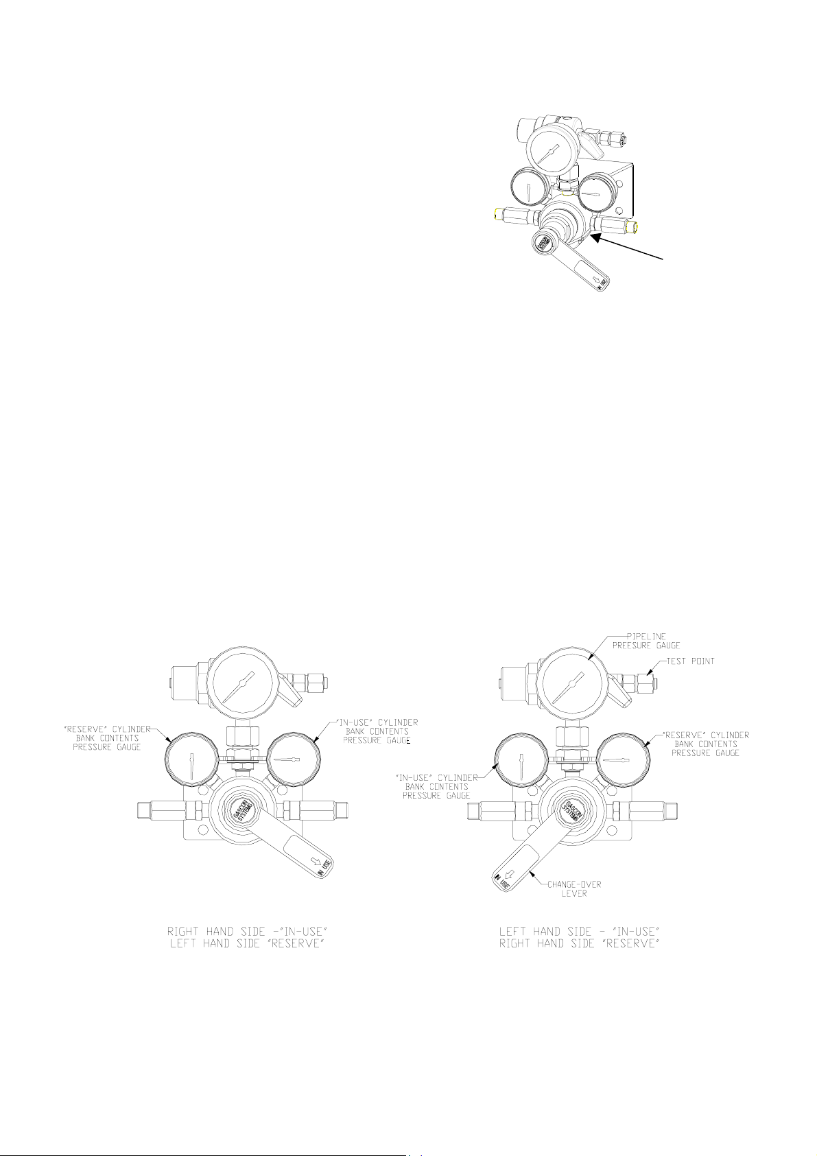
The diagram below shows how the “
position. The diagram also points out a few items referred to in this document.
” and “
in-use
reserve
” and “
” pressure settings,
reserve
” cylinder banks alternate according to the lever
M120-600-OXY
S/N 020125
GASCON SYSTEMS AUTO CHANGE-OVER AUGUST 2003 PAGE 3 of 11
MANIFOLD MAINTENANCE INSTRUCTIONS ISSUE 1
Page 4

3.0 TEST A - TEST GAS FAILURE ALARM SYSTEM
Any alarm systems connected to a manifold should be tested to ensure that they are operating correctly. To
check for the correct operation of the alarm system, refer to the alarm system manufacturers instructions.
The signals to alarm systems are usually generated from pressure switches. These pressure switches need to
drifted
be tested to ensure that their set point has not “
3.1 Change-over Pressure Switches
There are two methods of using pressure switches to indicate the change-over of cylinder banks. Using a two
pressure switch system, (one on each cylinder bank inlet to the manifold), or using a one pressure switch
system, (a pressure switch located at an intermediate point between the first and second stage manifold
regulators). Pressure switches may operate in Normally Open or Normally Closed modes, but Normally Open
is more commonly used in medical and critical process applications.
3.1.1 One Switch Systems
The one pressure switch system works on the pressure differential between the first stage regulator “
and “
reserve
” pressure settings. This is the more commonly used method for detecting the change-over of
cylinder banks. The more commonly used pressure settings are listed below.
“
RESERVE
PRESSURE
SETTING
750 kPa 1000 kPa 850 kPa 900 kPa 50 kPa
800 kPa 1100 kPa 920 kPa 980 kPa 60 kPa
1000 kPa 1250 kPa 1125 kPa 1175 kPa 50 kPa
2000 kPa 2700 kPa 2300 kPa 2500 kPa 140 kPa
”
“
IN-USE
PRESSURE
SETTING
”
P/SWITCH SET POINT
ON FALLING
The procedure for testing whether a one change-over pressure switch system is functioning correctly is the
same as that detailed in Test B (test function of manifold change-over mechanism). To check at what
pressure the switch is activated, a test gauge must be fitted to the manifold test point. On medical and critical
process application manifolds this can be done without interrupting the manifold operation by using the
isolation valve on the test point. On non-critical applications the flow to the pipeline may require to be
interrupted while fitting the test gauge. Monitor pressure on the test gauge as the manifold nears the changeover point. The pressure switch should activate at the specified set point. When re-opening the cylinder
valves, very slowly open the first valve and monitor at what pressure the switch is re-activated (reset)
3.1.2 Two Switch Systems
The two pressure switch system uses two pressure switches, or contact gauges, connected directly to the
cylinder contents side of each cylinder bank. These directly measure the cylinder pressure and are nominally
set to operate at 1.5 times the “
reserve
set point, and the deadband of the pressure switch are less critical on a two switch system than that for a one
switch system. The more commonly used pressure settings are listed below
” pressure setting specification of the manifold. The accuracy of the
“
RESERVE
PRESSURE SETTING
230 kPa 350 kPa
750 kPa 1130 kPa
1000 kPa 1500 kPa
2000 kPa 3000 kPa
”
” from their original settings.
MAXIMUM P/SWITCH
RESET ON INCREASING
PRESSURE
CHANGE-OVER
P/SWITCH SETTINGS
PRESSURE
in-use
MAXIMUM
P/SWITCH
DEADBAND
”
GASCON SYSTEMS AUTO CHANGE-OVER AUGUST 2003 PAGE 4 of 11
MANIFOLD MAINTENANCE INSTRUCTIONS ISSUE 1
Page 5

The procedure for checking whether a two change-over pressure switch system is the same as that detailed
in Test B (test function of manifold change-over mechanism). To check at what pressure the switches are
in-use
activated, monitor the pressure shown on the “
” bank contents pressure gauge as it nears the changeover point. When re-opening the cylinder valves, very slowly open the first valve and monitor at what
pressure the pressure is re-activated. This test can be carried out without interrupting the pipeline system on
medical manifolds, critical process applications and non-critical process applications.
3.2 Line Failure Pressure Switches
Unless otherwise specified, line failure pressure switches are set to operate when the pipeline pressure drops
below 0.8 times the nominal working pressure for medical pipeline system, and 0.7 times the nominal working
pressure for other pipeline systems. The more commonly used line pressure settings are listed below
Working
Gas
Medical Oxy, N2O, Air 415 kPa 330 kPa
Turbine Tool Air 1400 kPa 1120 kPa
Laboratory Gases 700 kPa 560 kPa
Incubator Gases 150 kPa 120 kPa
Nominal Pipeline
Pressure
Line Failure
P/switch Setting
(eg. medical oxygen with a nominal pipeline pressure of 415 kPa are set to operate when the pressure falls
below 0.8 x 415 = 330 kPa).
3.3 Emergency Backup Manifolds
If the manifold is being used as an emergency backup for another separate supply system, pressure switches
must be fitted to both
cylinder banks to monitor cylinder pressures. These pressure switches shall be set to
operate when the cylinder pressure drops below 75% of the nominal filling pressure, (eg. if nominal fill
pressure is 17,500 kPa, the pressure switch shall operate at 13,000 kPa).
Note:
Pressure switches should always be set to operate on a falling input pressure. After activating, the pressure
should be increased to check at what pressure the pressure switch resets, to ensure the deadband of the
pressure switch is not excessive.
Only personnel experienced in the testing of gas control equipment should test and adjust pressure switches.
4.0 TEST B - TEST FUNCTION OF MANIFOLD CHANGE-OVER MECHANISM
The manifold auto change-over mechanism should be tested to ensure it is functioning correctly. On systems
with an alarm system fitted, ensure that the appropriate personnel are notified prior to undertaking this test,
as this test should activate alarm signals.
To start this test, ensure the cylinders on the “
reserve
opened. Slowly close all the cylinder valves on the “
in-use
“
continue to drop until it reaches the “
” bank contents pressure gauge should start to drop, (with some flow through the flow). It should
reserve
” pressure setting of the manifold. At this point any change-over
alarm system fitted should have activated. The pressure on the
constant and there should no change in the pressure indicated on the pipeline pressure gauge. If the
reserve
“
” bank contents pressure gauge starts to rapidly drop, then there is a problem with the change-over
mechanism. Immediately re-open all the cylinder valves on the “
to its previous state. Seek further advice immediately.
If this first cylinder bank change-over test functioned correctly, the change-over mechanism for the other
cylinder bank direction must be checked. Move the change-over lever to the opposite position, (thus making
the “
reserve
” bank the “
in-use
” bank). Slowly fully open all the cylinder valves on the now “
cylinders (ie. the ones which were closed in the first half of this test). Close all the cylinder valves on the
” cylinder bank are full and their cylinder valves are fully
in-use
” cylinder bank. The pressure, as indicated on the
“reserve
in-use
” bank contents pressure should stay
” bank and the manifold should return
reserve
” bank of
GASCON SYSTEMS AUTO CHANGE-OVER AUGUST 2003 PAGE 5 of 11
MANIFOLD MAINTENANCE INSTRUCTIONS ISSUE 1
Page 6

in-use
newly selected “
the “reserve” setting pressure and any change-over alarms should activate. The “
pressure gauge should remain constant. If not, immediately open all the cylinder valves on the “
and seek further advice immediately.
After the change-over mechanism has been successfully tested in both directions it is important that all the
cylinder valves on both banks are fully opened and the change-over lever moved to a position where the
cylinder bank with the lowest pressure is made the “
General plant and equipment maintenance personnel who have received training in the procedure can
undertake testing the function of the change-over mechanism
Note:
There must be gas flowing through the manifold for the following tests to be undertaken properly.
” bank. As in the previous step, the "
in-use
in-use
” contents pressure gauge should drop to
reserve
” bank.
” bank contents
in-use
” bank
5.0 TEST C - TEST MANIFOLD PRESSURE SETTINGS
5.1 Primary or First Stage Pressure Settings
in-use
in-use
” and “
” and “
Test and re-adjust, if necessary, the “
regulators. To achieve this a test valve must be fitted to the manifold test point. On medical and critical
process applications the test point has an isolation valve so that test valve can be fitted without interrupting
the manifold operation. On non–critical process applications the manifold will be required to be isolated from
the pipeline system. Each manifolds “
sheet supplied with the manifold.
The procedure for testing/setting manifold first stage pressures are included in the Gascon systems Auto
Change-over Manifold Service Instructions, available to approved service personnel.
Only personnel experienced in the testing of gas control equipment, and who are familiar with Gascon
Systems recommended procedures should adjust the pressure settings of a manifold.
5.2 Pipeline or Second Stage Pressure Setting
Measure and re-adjust the manifold outlet pressure. This is pressure is shown on the 2-1/2” pipeline pressure
gauge. If this pressure needs to be reduced, ensure that there is a bleed flow downstream from the manifold
so that outlet pressure can be set correctly.
Note:
For medical manifolds, the maximum static (no flow) pipeline pressure is 1.1 times the nominal working
pressure (AS2896 Clause 3.7), eg. medical oxygen with nominal pipeline pressure of 415kPa, maximum static
pressure can be 1.1 x 415 = 460kPa
It is normal, good practices to set the static outlet pressure close to this maximum 460kPa in order to
maximize the flow performance of the manifold.
Flow performance is measured at 375kPa, 416kPa is the average pressure under flowing condition, 460kPa
includes seat closure, (approximately 20kPa at no flow conditions).
reserve
reserve
” pressure settings of the manifolds first stage
” pressure settings are included on the specification
GASCON SYSTEMS AUTO CHANGE-OVER AUGUST 2003 PAGE 6 of 11
MANIFOLD MAINTENANCE INSTRUCTIONS ISSUE 1
Page 7

6.0 TEST D - TEST PRESSURE RELIEF VALVES
crack
Remove the pressure relief valves from the pipeline and check to ensure they “
” and re-seat at the
required pressures. For medical manifolds with a G1135 three way service facilities the two pressure relief
valves fitted can be individually isolated and removed from the pipeline system without interrupting the
system operation.
Unless the pipeline has a pressure relief valve isolation system, this check cannot be done while the pressure
relief valves are fitted to the pipeline system. This applies to both critical and non-critical process applications.
Useless otherwise specified the pressure relief valves are set to crack between 1.3 and 1.4 times the nominal
pipeline pressure and reseat at a minimum of 1.2 times the nominal pipeline pressure. Commonly used
pressure relief valve settings are listed below.
Working
Gas
Medical Oxy, N2O, Air 415 kPa 540 kPa 580 kPa 500 kPa
Turbine Tool Air 1400 kPa 1820 kPa 1960 kPa 1680 kPa
Acetylene 150 kPa 195 kPa 210kPa 180 kPa
Laboratory Gases 700 kPa 910 kPa 980kPa 840 kPa
Nominal Pipeline
Pressure
Minimum PRV
cracking pressure
Maximum PRV
cracking pressure
Minimum PRV
re-seating pressure
Only personnel experienced in the testing of gas control equipment should test pressure relief valves.
7.0 TEST E – PRESSURE CONTROL ASSEMBLY SERVICE
The internal components of the pressure control assembly, (including seat capsules, diaphragms, non-return
valve seats, inlet filters), should be replaced. This servicing requires the manifold to be removed from the
pipeline system. The pipeline system must either be shutdown, or an auxiliary gas supply source be
connected to the pipeline system, (eg. through the G1135 three way service facility for medical manifolds).
This servicing requires that the manifold is dis-assembled, the recommended internal components be
replaced, re-assembled, tested and the pressure settings re-set prior to being put back into operation.
This procedure must only be undertaken by Gascon Systems approved service personnel using approved
spare parts and in accordance with factory approved procedures.
Note:
To reduce the amount of downtime required for this servicing, service exchange pressure control assemblies
are available on request. Service exchange pressure controls assemblies are manifolds that have been
previously returned, and been factory rebuilt to an “as new” operating condition.
8.0 TEST F – INSPECT FOR EXTERNAL LEAKS
The manifold assembly and inlet header system should be inspected for any leaks at all threaded connection
points. Connection points that should be tested are indicated in the diagram below and include:
- Connections between cylinder lead and header extensions,
- Connections between header extensions,
- Connections between header extensions and inlet arms,
- Connections into the first and second stage manifold bodies (such as gauges, relief valves,
outlet fitting, test point fittings, inlet non-return valves, pressure switches, …etc.).
The recommended method of testing for leaks is to apply a suitable leak detection solution, (eg Snoopy™,
Bubbles™), to all the indicated connections (*) while the system is pressurised, wait for five minutes and then
inspect for any bubbling of the solution.
GASCON SYSTEMS AUTO CHANGE-OVER AUGUST 2003 PAGE 7 of 11
MANIFOLD MAINTENANCE INSTRUCTIONS ISSUE 1
Page 8

General plant and equipment maintenance personnel can undertake the inspection for external leaks.
9.0 TEST G – INSPECTION OF CYLINDER LEADS
The flexible cylinder leads, or copper pigtails, should be inspected for any signs of metal fatigue, work
hardening or damage to threaded cylinder connection. The condition of any sealing washers or o-rings should
be inspected and replaced if necessary
General plant and equipment maintenance personnel can undertake the inspection of cylinder leads.
10.0 TEST H - CHECK THAT CYLINDERS HAVE BEEN CHANGED
The cylinders on each manifold bank should be checked to ensure that there are securely connected to the
manifold and that their cylinder valves are fully opened. The “
should indicate full cylinders, (unless the manifold has recently changed over). If the “
contents pressure gauge does not indicate full cylinders there could be a system leak, the cylinder valves
might not have been opened, an empty cylinder may have been connected accidentally, or there could be a
fault with the manifold.
At an appropriate time after a change-over has occurred it should be checked that the recently emptied
cylinders have been replaced with full cylinders.
General plant and equipment maintenance personnel can undertake the check that cylinders have been
changed.
reserve
” bank pressure contents pressure gauge
reserve
” bank pressure
11.0 TEST I - CHECK FOR EXCESSIVE FROSTING OR CONDENSATION
The manifold system should be visually checked for signs of excessive frosting or condensation build up on
the first stage manifold regulators. Excessive frosting may indicate a sign of system problems such as:
- leaks in the downstream pipeline system
- an under sizing of the manifold flow capacity for the system application
- extreme local environmental conditions around the manifold and cylinder supply systems.
General plant and equipment maintenance personnel can undertake the check for excessive
frosting/condensation
Note:
Some condensation on the manifold is normal, but continued excessive frosting may be solved by the addition
of gas heaters upstream of the manifold, or the addition of another stage of pressure reduction upstream of
the manifold. Frosting is most common of the liquifiable gases such as carbon dioxide, nitrous oxide, LPG,
…etc.
GASCON SYSTEMS AUTO CHANGE-OVER AUGUST 2003 PAGE 8 of 11
MANIFOLD MAINTENANCE INSTRUCTIONS ISSUE 1
Page 9

12.0 TEST J – TEST HEADER NON-RETURN VALVE FUNCTION
The non-return valves in the headers, (between the inlet extensions and the flexible leads/pigtails), function
should be checked. These valves are not designed to provide a 100% seal against reverse flow. They are
designed to stop rapid decanting in case an empty cylinder is accidentally connected to the manifold. A
reverse flow of several litres per minute is acceptable. If any cylinders are to be removed from the manifold
for extended periods of time, the inlet connections should be fitted with blanking plugs.
13.0 TEST K – TESTING OF FLASHBACK ARRESTORS
Any flashback arrestors fitted to pipeline system should be removed and tested for the following:
- flow performance
- leak tightness
- correct function of non-return valves
- visible signs of flashbacks
Refer to the flashback arrestor manufacturers’ recommendations for testing.
Personnel experienced in testing flashback arrestors, using flashback arrestors’ manufacturer recommended
test equipment and test procedures, should undertake the testing of flashback arrestors.
14.0 TEST J - INSPECT FOR UNAUTHORIZED MODIFICATIONS
The manifold system should be visually inspected for any signs of authorized modifications since the last
inspection. Such modification may include:
- removal or addition of valves
- removal, dis-connection or addition of pressure switches
- removal or replacement of system components
- addition of new piping
- bending or replacement of cylinder leads or pigtails
- removal of system operating instructions
General plant and equipment maintenance personnel can undertake the inspection for authorized modification
to a manifold.
15.0 PRESSURISING AND RE-PRESSURING PIPELINE SYSTEM
When initially pressuring, or re-pressuring the manifold/pipeline system after maintenance/servicing it in
important that it is done in a controlled manner. Allowing the manifold rapidly pressurise an empty pipeline
system can damage the regulator seats. The recommended procedure for pressurizing the system is to:
- Close the isolation valve immediately downstream of the manifold,
- Partially open the first cylinder very slowly, allow the pressure (as shown on the inlet content
gauges to increase slowly,
- After the inlet pressures have stablised, open the remaining cylinder valves,
- Partially open the system isolation valve slowly, and let the pipeline slowly pressurise, (do not
fully open the valve at this stage),
- After the pipeline pressure has stabilsed, fully open the isolation valve.
GASCON SYSTEMS AUTO CHANGE-OVER AUGUST 2003 PAGE 9 of 11
MANIFOLD MAINTENANCE INSTRUCTIONS ISSUE 1
Page 10

16.0 GASCON SYSTEMS AUTO CHANGE-OVER MANIFOLD MAINTENANCE SCHEDULE
for medical and critical process applications
MAINTENANCE
TEST
ON SYSTEM
COMMISSIONING
EVERY
WEEK
A – Test gas failure alarm system YES - - - YES - - B – Test function of change-over system YES - - YES - - - C – Check manifold pressure settings YES - - - - YES - D - Test pressure relief valves - - - - - YES - E – Service pressure control assembly - - - - - - YES F – Inspection for external leaks YES - - - YES - - YES
G – Inspection of cylinder leads YES - - - YES - - YES
H - Check that cylinder have been changed YES YES - - - - - YES
I – Check for excessive frosting/condensation YES - - YES - - - YES
J – Test header non-return valves - - - - - - YES K – Testing of flashback arrestors - - - - - YES - L – Inspect for unauthorized modifications YES - - - - YES - -
RECOMMENDED FREQUENCY OF TESTING
EVERY
MONTH
EVERY
THREE
MONTHS
EVERY
SIX
MONTHS
EVERY
YEAR
EVERY
THREE
YEARS
WHENEVER
CHANGING
CYLINDERS
GASCON SYSTEMS AUTO CHANGE-OVER AUGUST 2003 PAGE 10 of 11
MANIFOLD MAINTENANCE INSTRUCTIONS ISSUE 1
Page 11

17.0 GASCON SYSTEMS AUTO CHANGE-OVER MANIFOLD MAINTENANCE SCHEDULE
for non critical process applications
MAINTENANCE
TEST
ON SYSTEM
COMMISSIONING
EVERY
WEEK
A – Test gas failure alarm system YES - - - YES - B – Test function of change-over system YES - - YES - - C – Check manifold pressure settings YES - - - - YES - D - Test pressure relief valves - - - - - - YES- E – Service pressure control assembly - - - - - - YES F – Inspection for external leaks YES - - - YES - - YES
G – Inspection of cylinder leads YES - - - YES - - YES
H - Check that cylinder have been changed YES YES - - - - - YES
I – Check for excessive frosting/condensation YES - - - YES - - YES
J – Test header non-return valves - - - - - - YES K – Testing of flashback arrestors - - - - - YES - L – Inspect for unauthorized modifications YES - - - - YES - -
RECOMMENDED FREQUNCY OF TESTING
EVERY
MONTH
EVERY
THREE
MONTHS
EVERY
SIX
MONTHS
EVERY
YEAR
EVERY
FIVE
YEARS
WHENEVER
CHANGING
CYLINDERS
GASCON SYSTEMS AUTO CHANGE-OVER AUGUST 2003 PAGE 11 of 11
MANIFOLD MAINTENANCE INSTRUCTIONS ISSUE 1
 Loading...