

Page 1
Introduction
Purpose of this Manual
This manual contains information on the installation of the Blackmer® XU2A rebuild kit as
used in Gasboy
This manual is written for Gasboy Authorized Service Contractors (ASCs) who will be
installing the kit. It is recommended that only ASCs install this ki t.
Important Notice
Blackmer XU2A pumps must only be installed in systems which have been designed by
qualified engine er ing personnel. The system mu st conf orm to all applicable local and national
regulations and safety standards.
All parts and required kits are listed in the Blackmer Parts List at the rear of this document.
This manual MUST be kept with the pump.
®
self-contained products.
MDE-4320
Gasboy UHF Pump, Blackmer® XU2A
Rebuild Kit Installation Manual
June 2004
Required Reading
Before servicing the pump, the technician must read, understand, and follow
this manual .
Failure to do so may adversely effect the safe use and operation of the equipment.
Related Documents
Document Number Document Name GOLD® Library
035297 Series 9800A Pump/Dispensers
Note
The "Note" designation indicates within the manual special instructions which are very
important and must be followed.
Parts List
Gasboy Commercial & Retail Pumps
MDE-4320 Gasboy UHF Pump , Blac k m er® XU2A Rebuild Kit Installatio n Ma nu al • Jun e 20 04 Page 1
Page 2
Introduction
Required Tools
Acronym Table
The following table contains a list of acronyms used in this manual.
• 5mm Allen® wrench
• 1/4-inch allen wrench
• heavy snap ring pliers
• ratchet wrench
• 16mm sock et
• 13mm or 1/2-inch socket
• rubber mallet
• torque wrench
Acronym Definition
ASC Authorized Service Contractors
cmhg centimeter of mercury
CW Clockwise
CCW Counterclockwise
GDP Global Dispenser Pump
gpm gallons per minute
inhg inch of mercury
lbs pound-force
lbs-in pound-inch
lpm liters per minute
mm millimeter
N/A not applicable
Nm newton-meter
OIML International Organization of Legal metrology*
Opt. Optional
PCV Pressure Control Valve
psi pounds per square inch
Std Standard
UHF Ultra High Flow
*OIML Switch (optional) monitors air to fuel mix and is used primarily in
Europe.
Page 2 MDE-4320 Gasboy UHF Pump, Blackmer® XU2A Rebuild Kit Inst allat ion Ma nual • June 2004
Page 3

Important Safety Information
This section introduces the hazards and safety precautions associated with installing,
inspecting, maintaining or servicing this product. Before performing any task on this product,
read this safety information and the applicable sections in this manual, where additional
hazards and safety precau ti ons for your task will be found. Fire, exp los ion, electrical shock or
pressure release could occur and cause death or serious injury if these safe service procedures
are not followed.
Preliminary Precautions
You are working in a potentially dangerous e nvi ronment of flammable fuels, vap ors, and high
voltage or pressures. Only trained or authorized individuals knowledgeable in the related
procedures should install, inspect, maintain or service this equipment
Emergency Total Electrical Shut-Off
The first and most important information you must know is how to stop all fuel flow to the
pump and island. Locate the switch or circuit brea kers that shu t-off all power to all fueling
equipment, dispensing devices, and submerged turbine pumps (STPs).
Important Safety Information
.
!
WARNING
The EMERGENCY STOP, ALL STOP, and PUMP STOP buttons at the cashier’s
station WILL NOT shut off electrical power to the pump/dispenser.
This means that even if you activate these stops, fuel may continue to flow
uncontrolled.
You must use the TOTAL ELECTRICAL SHUT-OFF in the ca se of a n em erg enc y and
not only these cashier station “stops.”
Total Electrical Shut-Off Before Access
Any procedure requiring access to electrical components or the electronics of the dispenser
requires total electrical shut-off of that unit. Know the function and location of this switch or
circuit breaker before in specting, installing, maintaining, or s ervicing Gilbarco
®
equipment.
Evacuation, Barricading and Shut-Off
Any procedures requiring accessing the pump/dispenser or STPs requires the following three
actions:
• An evacuation of all unauthorized persons and vehicles
• Using safety tape or cones as barricades to the effected units
• A total electrical shut-off of that unit and any associated STPs.
MDE-4320 Gasboy UHF Pump, Blackmer® XU2A Rebuild Kit Installation Manual • June 2004 Page 3
Page 4
Important Safety Information
Read the Manual
Read, understand and follow this manual and any other labels or related materials supplied
with this equipment. I f y ou do not understand a procedure , ca ll a Gilbarco Authorized S erv ic e
Contractor or call the Gilbarco Call Center at 1-800-800-7498. It is imperative to your safety
and the safety of others to understand the procedures before beginning work.
Follow the Regulations
There is ap plicable info rmation in: NFPA 30A: Automotive and Marine Service Code; NFPA
70: National Electrical Code (NEC); OSHA regulations; and federal, state, and local codes
which must be followed. Failure to install, inspect, maintain or service this equipment in
accordanc e with these codes, regul ations and sta ndards may lead to legal citations with
penalties or affect the safe use and operation of the equipment.
Replacement Parts
Use only genuine Gilbarco replacement parts and retrofit kits on your pump/dispenser. Using
parts other than genuine Gilbarco replacement parts could create a safety hazard and violate
local regulations.
Safety Symbols and Warning Words
This section provides important information about warning symbols and boxes.
Alert Symbol
This safety alert symbol is used in this manual and on warning labels to alert you to a
precaution which must be followed to prevent potential personal safety hazards. Obey safety
directives that follow this symbol to avoid possible injury or death.
Signal Words
These signal words used in this manual and on warning labels tell you the seriousness of
particular safety hazards. The precautions that follow must be followed to prevent death,
injury or damage to the equipment
• DANGER - This signal word is used to al ert you to a haza rd to uns afe pract ice whic h will
result in death or serious injury
• WARNING - This alerts you to a hazard or unsafe practice that could result in death or
serious injury.
• CAUTION with Alert symbol - This signal word designates a hazard or unsafe practice
which may re sult in minor injury.
• CAUTION without Alert symbol - When used by itself, CAUTION designates a hazard
or unsafe practice which may result in property or equipment damage.
Prevent Explosions and Fires
Fuels and their vapors will become explosive if ignited. Spilled or leaking fuels cause vapors.
Even filling customer tanks will cause explosive vapors in the vicinity of dispenser or island.
Page 4 MDE-4320 Gasboy UHF Pump, Blackmer® XU2A Rebuild Kit Ins tallat ion Ma nual • June 2004
Page 5
Important Safety Information
No Open Flames
Open flames from matches , l i ght ers , we ldi ng torches or other sources can ignite fuels
and their vapors.
No Sparks - No Smoking
Sparks from starting ve hicl es, sta rting or usi ng power tool s, burni ng cig arett es, ci gars
or pipes can also ignite fuels and their vapors. Static electricity, including an electrostatic
charge on your body, can cause a spark suffic ient t o ignite fuels and their vapors. Afte r getting
out of a vehicle, touch the metal of your vehicle to discharge any electrostatic charge before
you approach the dispenser island.
Working Alone
It is highly recommended th at someone who is capabl e of render ing fi rst aid be present during
servicing. Be f amili ar with Car diopulmonar y Resusc itat ion ( CPR) met hods i f yo u are worki ng
with or around high voltages. This information is available from the American Red Cross.
Always advise the st ation perso nnel a bout whe re you will be wor kin g, and c autio n them not to
activate power while you are working on the equipment. Use the OSHA tag out and lock out
procedures. If you are no t familiar with this requirement, refer to information in the service
manual and OSHA documentation.
Working With Fuel Safely
Be sure to follow information in this manual, related materials and approved industry standard
practices in handling fuel and fueling equipment.
Protect Your Eyes
Spraying fuel from residual pressure in lines can cause serious eye injuries. Always
wear eye protection. Gasoline spilled in eyes may cause burns to eye tissue. Rinse eyes with
water for approximately 15 minutes. Seek medical advice immediately. It is not necessary to
wear eye protection unless performing hydraulic service.
Use Proper Fuel Handling Techniques
• Be sure breakaways, shear valves and other emergency devices are properly installed.
Refer to manufacturer’s instructions for proper installation.
• Collect, transport and dispose fuel only in approved containers specifically designed for
this purpose.
• Before working with any chemicals or fuels in and around a dispensing facility, read the
MSDS pertaining to those chemicals as prescribed in the Occupational Safety and Health
Administration Standard, 29 CFR 1910.1200. Refer to the supplier’s literature.
MDE-4320 Gasboy UHF Pump, Blackmer® XU2A Rebuild Kit Installation Manual • June 2004 Page 5
Page 6
Important Safety Information
Hydraulic Pressure Releases and Fuel Leakage
Working on hydraulic systems can result in leakage of fuel that may also be under pressure.
grades of fuel, and all associated STPs.
Do not allow unauthorized or untrained individuals to service hydraulic equipment.
Shear valves, require d by NFPA 30A, are inten ded t o s hut -off the flow of fuel at the dispenser
base (hydraulics area ) during vehicl e impact or fir es. A single-poppe t shear valve pr events fuel
from flowing from the underground tank. A double-poppet shear valve prevents fuel from
flowing from the underground tank and from the dispenser.
React Quickly to Fuel Spills, Fires or Vehicle Impact
Follow these steps in th e event of a fuel spill, fire, or vehicle impact.
Turn off all circuit breakers for unit being worked on, all dispensers using the same
1 Use station EMERGENCY TOTAL ELECTRICAL SHUT-OFF immediately. Turn off all
system circuit breakers to the island. Refer to “
page 3 for more information.
2 Call emergency numbers for fires, vehicle impact or any significant spills.
3 Use safety tape, cones or barricades to block the work area. Do not go near fuel spill or allow
anyone else in the area.
4 Take precautions to avoid igniting fuel. Do not allow starting of vehicles in the area and
immediately stop use of open flames, smoking or power tools in the area.
5 Provide emerge ncy and f irst aid a ssistanc e. If a ny g asoli ne has b een inh aled or spil led on s kin,
seek emergency help immediately.
6 Use approved and safe procedures to clean up all spills with a “fuel or gasoline absorbent”
material approved b y your local r egulator y agenci es. (Dispo se of f uel and h azardous absorb ent
material promptly and according to the requirements of the fire department, local EPA, and
federal, state or local resources.)
Working With Electricity Safely
Be sure to use safe and established practices in working with electrical devices. Poorly wired
devices may cause a fire, explosion or electrical shock.
• Be sure grounding connections are properly made.
• Make sure that sealing devices and compounds are in place.
• Be sure not to pinch wire s when repla cing covers
• Follow OSHA Lock-Out and Tag-Out requirements. Station employees and service
contractors need to understand and comply with this program completely to ensure safety
while the equipment is down.
T otal Electrical Shut-Off Before Access” on
Page 6 MDE-4320 Gasboy UHF Pump, Blackmer® XU2A Rebuild Kit Ins tallat ion Ma nual • June 2004
Page 7
Hazardous Materials
Some materials prese nt inside e lectroni c enclosur es may pre sent a heal th hazard i f not handl ed
correctly. Be sure to clean hands after handling equipment. Do not place any equipment in
mouth.
!
WARNING
This area contains a chemical known to the State of California to cause cancer.
!
WARNING
This area contains a chemical known to the State of California to cause birth defects or
other reproductive harm.
Emergency First Aid Infor mation
!
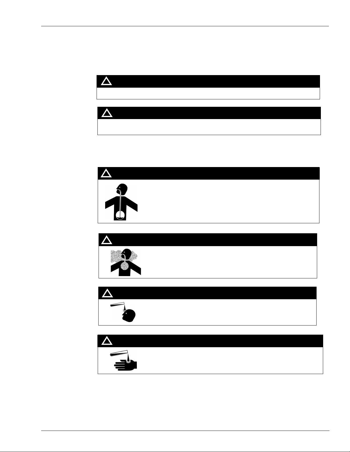
WARNING
Gasoline ingested may cause unconsciousness and burns to internal organs.
Do not induce vomiting.
Keep airway open.
Oxygen may be needed at scene.
Seek medical advice immediately.
Important Safety Information
!
WARNING
WARNING
!
!
WARNING
Gasoline inhaled may cause unconsciousness and burns to lips, mouth
and lungs.
Keep airway open.
Seek medical advice immediately.
Gasoline spilled in eyes may cause burns to eye tissue.
Irrigate eyes with water for approximately 15 minutes.
Seek medical advice immediately
Gasoline spilled on skin may cause burns.
Wash area thoroughly with clear/water.
Seek medical advice immedi ately.
MDE-4320 Gasboy UHF Pump, Blackmer® XU2A Rebuild Kit Installation Manual • June 2004 Page 7
Page 8

Important Safety Information
Informing Emergency Personnel
Compile the following information for emergency personnel:
• Location of accident (e.g. address, front/back of building, etc.)
• Nature of accident (e.g. possible heart attack, run over by car, burns, etc.)
• Age of victim (e.g. baby, teenager, middle-age, elderly)
• Whether or not victim has received first aid (e.g. stopped bleeding by pressure, etc.)
• Whether or not victim has vomited (e.g. if swallowed or inhaled something, etc.)
IMPORTANT: Oxygen may be needed at scene i f gasoli ne has b een ingest ed or inha led. Seek
medical advice immediately.
Page 8 MDE-4320 Gasboy UHF Pump, Blackmer® XU2A Rebuild Kit Ins tallat ion Ma nual • June 2004
Page 9

Pump Data
XU Pump Models Pump Size
Maximum Pum p
Speed (RPM)
Maximum Differential
Pressure
Maximum Working
Pressure
Initial Start Up Information
Model No. __________________________________________
Serial No.___________________________________________
Date of Installation:__________________________________
Pressure Gauge Reading: _____________________________
Vacuum Gauge Reading:______________________________
Flow Rate:__________________________________________
Pump Data
1.5" 2"
780 500
50psi (344 kPa)
175 psi (1207 kPa)
MDE-4320 Gasboy UHF Pump, Blackmer® XU2A Rebuild Kit Installation Manual • June 2004 Page 9
Page 10

Installation
Installation
Note: Blackmer power pumps must only be installed in systems designed by qualified
engineering personnel per NFPA 30 or 30A. system design must conform with all
applicable regulations and codes and provide warning of all system hazards.
WARNING
!
Pre-insta llation Cleaning
Hazardous voltage can shock, burn or cause death.
- Install, ground and wire to local and National Electrical Code requirements.
- Install an all-leg disconnect switch near the unit motor.
- Disconnect and lockout electrical power before installation or service.
- Electrical supply MUST match motor nam ep lat e spec ifi ca tio ns .
- Motors equipped with thermal protection automatically disconnect motor electrical
circuit when overload exists. Motor can start unexpectedly and without warning.
Location and Piping
Pump life and performance will be significantly reduced when installed in an improperly
designed system. Before starting the layout and installation of the piping system, review the
following suggestions:
1 Locate the pump as near as possible tot he source of supply to avoid excessive inlet pipe
friction.
2 The inlet line should be at least as large as the intake port on the pump. It should slope
downward to the pump, and should not contain any upward loops. Eliminate restrictions such
as sharp bends; globe valves, unnecessary elbows, and undersized strainers.
3 A strainer must be installed in the inlet line to prote ct the pump form foreign matter. The
strainer should be locat ed at least 24 in ches (0.6m) from th e pump, and have a net open ar ea of
at least four times the area of the intake piping. Strainers must be cleaned regularly to avoid
pump starvation.
CAUTION
!
Foreign matter entering the pump will cause extensive damage. Ensure that the
supply tank and intake piping have been cleaned and flushed prior to pump
installation and operation.
4 The intake and discharge piping system must be free of all leaks.
5 Expansion joints, placed at least 36 inches (0.9m) from the pump, will compensate for
expansion and contraction of the pipes. Contact the flexible connector/nose manufacturer for
required maintenance/ care and design assistance in their use.
6 All piping and fittings must be properly supported to prevent any piping loads from being
Page 10 MDE-4320 Gasboy UHF Pump, Blackmer® XU2A Rebuild Kit Installation Manu al • June 2004
Page 11

Installation
placed on the pump.
7 Install pressure gauges in the NPT ports provided in the pump casing to check pump
performance at start up.
8 Check alignment of pipes to pump to avoid strains, which might later cause misalignment.
Unbolt flanges or break union joints. Pipes should not spring away or drop down. After pump
has been in operation for a week or two, completely recheck alignment.
Pump Mounting
It is recommended that the unit be permanently mounted by securing the base plate with
adequately sized anchor bolts to a level concrete floor following recommended industry
standards. A solid foundation will reduce system noise and vibration, and will improve pump
performance. Refer to ANSI/HI standards or a suitable pump handbook for information on
typical pump mounting and foundations. Check coupling alignment after pump and base
assembly is secured to the foundation.
Figure 1: Alignment Check
Couple Alignment
The pump must be directly coupled to a gear reducer and /or driver with a flexible coupling.
Both angular and parallel coupling alignment must be maintained between the pump, gear,
motor and so on in accordance with manufacture’s inst ructions. See Figure 1:Alignment
Check.
1 Parallel alignment: The use of a laser alignment tool or dial indicator is preferred. If a laser
alignment tool or dial indictor is not available, use a straightedge. Turn both shafts by hand,
checking the reading through one complete revolution. Maximum offset should be less than
.005 inch (0.127mm).
2 Angular alignment: In sert a feel er gauge bet ween the coupli ng halves. Chec k the spacing at 90
degree increments around the coupling (four check points). Maximum variation should not
exceed 0.005 (0.127mm). Some laser alignment tools will check angular alignment as well.
3 Replace the coupling guards after setting alignment.
MDE-4320 Gasboy UHF Pump, Blackmer® XU2A Rebuild Kit Installation Manual • June 2004 Page 11
Page 12

Installation
WARNING
!
Operation without guards in place can result in serious personal injury,
major property damage, or death.
Pump Rotation
To determine pump rotation:
If the intake port and the relief valve are on the right, with the drive end of the shaft pointing
towards the observer, the pump in right-handed, or clockwise rotation.
Note: Confirm correct pump rotation by checking the pump rotation arrows respective to
pump driver rotation.
To Change Pump Rotation
T o reve rse the pump rotat ion, remove both the inboard head and outboard head (20), and r otate
the cylinder (12) 180 degrees. so that the intake port is on the opposite side. Remove and
replace the vanes (14) with the relief grooves facing in the direction of pump rotation. Refer to
the "Maintenance" Sect ion of this manual for inst ruc ti ons o n pump di sas se mb ly a nd as sembl y.
Page 12 MDE-4320 Gasboy UHF Pump, Blackmer® XU2A Rebuild Kit Installation Manu al • June 2004
Page 13

Operation
1 Inspect complete piping system and supports to ensure that no piping loads are being placed
Operation
Pressure Control Va lve Adjustment
Pressure Control Valves (PCV) must be set to the desired single hose operation pressure.
A retaining ring must be in place at all times during pressure control valve adjustment.
!
WARNING
Operation without guards in place can cause serious personal injury, major property
damage or death.
Operating pump against a closed valve can cause system component failure, personal
injury and property damage.
on the pump.
2 Ensure all valves and fittings in piping system are in the start-up or operating positions.
3 Jog the pump motor to verify proper pump rotation.
Start Up Procedures
Note: Consult the "Troubleshooting" of this manual if difficulties during start-up occur.
1 Start the motor. Priming should occur within one minute.
2 Check the vacuum and pressure gauges to ensure the system is operating within expected
parameters. Record the gauge readings in the "Initial Start Up Information" section of this
manual for future reference.
3 Inspect piping, fittings, and associated system equipment for leaks noise, vibration and
overheating.
4 If possible , check the flow rate to ensure the pump is operating within the expected
parameters. Record flow rate in the "Initial Start Up Information" section of this manual.
!
WARNING
Incorrect settings of the pressure relief valve can cause system component failure,
personal injury and property damage.
5 Check the pressure setting of the relief valve by momentarily closing a valve in the discharge
line and reading the pressure gauge, this pressure should be 10 - 20 psi (69 - 138 kPa) higher
than the maximum system operating pressure, or the external bypass valve setting
MDE-4320 Gasboy UHF Pump, Blackmer® XU2A Rebuild Kit Installation Manual • June 2004 Page 13
Page 14

Operation
(If equipped). DO NOT operate the pump against a closed discharge valve for more than 1
minute.
Reverse Rotation
Note: Pump should be operated in reverse rotation for no more than 10 minutes and only
when a separate pressure relief valve is installed to protect the pump from excessive
pressure.
It may be desira ble t o run t he p ump in rever se r otati on f or sy st em maint enance . The pump wil l
operate sat isfactorily in reverse rota tion for a LIMI TED time, at a reduced performance level.
Flushing the Pump
1 To flush the pump, run the pump with the discharge valve open and the intake valve closed.
Bleed air into t he pump th rou gh the i ntake gau ge plug hole or thro ugh a la r ger auxil iary fitt in g
in the intake piping. Pump air for 30 seconds intervals to clean out most of the pumpage.
2 Run a system compatible flushing fluid through the pump for one minute to clear out the
remainder of the original pumpage.
3 To remove the flushing fluid, follow step 1 above.
Note: Some residual fluid will re main in the pump and piping.
Note: Properly dispose of all waste fluids in accordance with the appropriate codes and
regulations.
Pump Relief Valve
Note: The pump internal relief valve is designed to protect the pump from excessive pressure
and must not be used as a system pressure control valve.
Pumping volatile liquids under suction lift may cause cavitation. Partial closing of the
discharge valve will result in internal relief valve chatter and is not recommended. For these
applications, inst all an ext ernal sy stem press ure con trol val ve and any ne cessary by pass pipi ng
back to the storage tank.
A system pressure control valve is also recommended when operating for extended periods
(more than 1 minute) against a closed discharge valve.
Relief Valve Setting
The factory relief va lve press ure sett ing is marke d on a metal ta g attache d to the valve cover. It
is recommended that the relief valve be set at least 10 -20 psi (69 - 138 kPa) higher than the
operating pressure or the system pressure control valve setting.
Page 14 MDE-4320 Gasboy UHF Pump, Blackmer® XU2A Rebuild Kit Installation Manu al • June 2004
Page 15

Operation
!
WARNING
Relief valve cap is exposed to pumpage and will contain some fluid.
!
CAUTION
Incorrect settings of the pressure relief valve can cause system component failure,
personal injury and property damage.
Relief Valve Adjustment Procedure
Note: Numerical references are include d to indicate part identification, reference the
exploded assembly drawing under Blackmer Parts List at the end of this manual.
1 To increase the pressure setting, remo ve the relief v alve cap (1) and gasket (88) if equipped.
Turn the adjusting screw (2) inward, or clock wise. Inspect R/V cap gasket (88) and repla ce as
required. Reattach R/V cap gasket (88) and replace as required. Reattach R/V cap gasket and
R/V cap if equipped.
2 To decrease the pressure setting, remove the relief valve cap (1) and gasket (88) if equipped.
Turn the adjusting screw (2) outward, or counter clockwise. Inspect R/V cap gasket (88) and
replace as required. Reattach R/V cap gasket (88) and replace as required. Reattach R/V cap
gasket and R/V cap if equipped.
Refer to corresponding Blackmer Parts List for relief valve spring pressure ranges.
MDE-4320 Gasboy UHF Pump, Blackmer® XU2A Rebuild Kit Installation Manual • June 2004 Page 15
Page 16

Pump Maintenance
Pump Maintenance
!
DANGER
Failure to disconnect and lockout electrical power before attempting maintenance can
cause serious personal injury or death.
!
WARNING
If pumping hazardous or toxic fluids, system must be flushed and decontaminated,
inside and out, prior to performing maintenance.
!
WARNING
Failure to relieve system pressure prior to performing pump service or maintenance
can cause personal injury or property damage
!
DANGER
When pump is running disconnecting any part of the liquid system, pipe, strainer,
hose, nozzle, etc. can cau se serious person al injury, death or major property dama ge.
Note: Maintenance shall b e performed by q ualified t echnicians on ly follow ing the appr opri ate
procedures and warnings as presented in this manual.
Scheduled Maintenance
Strainers:
Strainers must be cleaned regularly to avoid pump starvation. Schedule will depend upon the
application and operating conditions.
Pump Lubrication
The pump’s ball bearings must be lubricated every three months at minimum. More frequent
lubrication may be required, depending on the application and the operating conditions.
Recommended Grease:
®
Exxon
Mobile
Page 16 MDE-4320 Gasboy UHF Pump, Blackmer® XU2A Rebuild Kit Installation Manu al • June 2004
- Ronnex MP Grease
®
- Mobilith AW-2 (64353-6) Grease, or equivalent.
Page 17

Pump Maintenance
Greasing Procedure:
1 Remove the grease relief fittings (76A) from the bearing covers (27, 27A).
2 Slowly apply grease with a hand gun until the grease begins to escape from the grease relief
fitting port. Discard excess grease in accordance with the proper codes and regulations.
3 Replace the grease relief fittings (76A).
Do not over grease pump bearings. While it is normal for some grease to escape from the grease
tell-tail hole after lubrication, excessive grease on pumps equipped with mechanical seals can
cause seal failure. The tell-tall hole is located in the head between the bearing and the seal.
Vane Replacement
Note: Follow all hazard warnings and instructions provided in the "Pump Maintenance"
section of this manual.
1 Drain the pump and system as required.
2 Remove the head assembly from the outboard (non-driven) side of the pump according to
steps 5 - 8 in the "Pump Disassembly" section of this manual.
3 Turn the shaft by hand until a van (14) comes to the top (12 o’clock) position of the rotor.
Remove the vane.
4 Install a new van, ensuring that the rounded edge is up, and the relief grooves are facing
towards the direction of rotation. See Figure 2:Vane Installation.
5 Repeat steps 2 and 3 until all vanes have been replaced.
6 Reassemble the pump according to steps 2 - 6 and 10 - 13 of the "Pump Assembly" section of
this manual .
Figure 2: Vane Installation
ROUNDED EDGE OUT
RELIEF GROOVES FACE IN
DIRECTION OF ROTATION
Note: Follow all hazard Warnings and Instructions provided in the "Pump Maintenance"
MDE-4320 Gasboy UHF Pump, Blackmer® XU2A Rebuild Kit Installation Manual • June 2004 Page 17
Page 18

Pump Maintenance
section of this manual.
1 Drain the pump and system as required.
2 Starting on the inboard (driven) end of the pump, clean the pump shaft thoroughly, making
sure he sha ft is free of ni cks and burrs . This will prevent damage to the mechanical seal w hen
the inboard head assembly is removed.
3 Remove the inboard bearing cover capscrews (28) and slide the inboard bearing cover (27A)
and gasket (26) of f the shaft . Disca rd the gasket . The dir t shi eld wil l come off with the bearing
cover. Inspect dirt shield and replace as required.
4 Remove the outboard bearing cover capscrews (28) and bering cover gasket (26). Discard the
bearing cover gasket.
5 Remove the head capscrews (21) and carefully pry the head (20) away from the cylinder (12).
6 Slide the head of f the sha ft. The head O-r ing (72), b earing (24 ), and mechani cal seal ( 153) will
come off with the head assembly. Remove and discard the head O-ring.
a. Pull the bearing (24) from the housing in the head.
b. To remove the mechanical seal, use two screw drivers against the backside of the seal
jacket to gent ly pus h t he seal from the h ead (s ee Figure 3:Mechanical Seal Removal). Use
care when placing the screw drivers to prevent damage to the seal faces. Remove and
discard the seal O-rings.
Figure 3: Mechanical Seal Removal
7
Pull the rotor and shaft (13) from the cylinder. While one hand is pulling the shaft, the other
hand should be cupped underneath the rotor to prevent the vanes (14) and pushrod (77) from
falling out. Carefully set the rotor and shaft aside for future van e replaceme nt and reassembly.
8 Remove the remaining compone nts from the outboard si de of the pump a s instruc ted in step s 7
and 8 above.
Pump Assembly
Before reassembling the pump, insp ect all component parts fo r wear or da mage and replace as
required. Wash out the bearing/seal races of the head and remove any burrs or nicks from the
Page 18 MDE-4320 Gasboy UHF Pump, Blackmer® XU2A Rebuild Kit Installation Manu al • June 2004
Page 19

Pump Maintenance
rotor and shaft.
1 Reassemble the outboard side of the pump first.
a. For a clock wise rotation pump, position the pump cylinder with the intake port to the
left.
b. For a counterclockwise rotation pump, position the pump cylinder with the intake port
to the right .
2 Apply a small amount of quality O-ring lubricant in the head recess. With new O-rings
installed, push the mechanical seal assembly (153) into the recess of the head with the seal
jacket drive tangs inwa rd. The pi n in the s eal st ationa ry seat must between the lugs in the ba ck
of the head recess.
3 Apply a small amount of qual ity O-rin g lubrican t to the O-ri ng groove on t he inside f ace of the
head to facili tate inst allat ion. I nstal l a new head O-r ing ( 72) i n the groove by la yin g the O-ring
flat and starting in on one side of the groove, stretching ahead with the fingers as show in
Figure 4:Head O-Ring Installation.
4 Install the head (20) on the outboard side of the cylinder. Install and snug up four head
capscrews (21) 90° apart.
5 Hand pack the ball bearing (24) wit h grease. Refer to "Lubrication" in th e Pump Maint ena nce
Section for the recommended grease.
6 Install the bearing into the head recess. The bearing balls should face outward with the grease
shield inward. Ensure that bearing is fully and squarely seated against the mechanical seal.
7 Turn the pump cylinder around and begin assembly on the opposite inboard end.
8 Remove the vanes (14) and push rods (77) from the roto r a nd s haf t assembly. Inspect for wear
and damage and replace as follows:
a. Partially install he non-driven end of the rotor and shaft (13) into the open side of the
pump cylinder.
b. Leave part of the rotor outside of the cylinder so that the bottom vanes can be installed
and held in pla ce as the push rods a re installed in th e p u sh ro d holes of the rot or. Insert the
new vanes into the rotor sl ots wit h the rounded edges outward and th e vane rel i ef grooves
facing towards the direction of rotation. Refer to Figure 2:Vane Installation.
c. After the bottom vanes and push rods are installed, insert the rotor and shaft fully into
the cylinder.
d. Install the remaining vanes into the top positions of the rotor. Rotate the shaft by hand to
engage the drive tangs of the mechanic al seal jacket in the rotor slots.
9 Apply a thin coating of quality O-ring lubricant on the inboard shaft to aid installation.
Installation. Install the inboard head, mechanical seal, and bearing as instructed in steps 2
through 6.
10 Rotate the shaft by hand to engage t he seal dr ive tang s, and to tes t for bind ing or ti ght spots . If
the rotor does not tur n fr eely lightly tap the ri ms of t he heads with a soft faced mall et until the
correct position is found. Install all of the remaining head capscrews for each head and
uniformly tighten , torquing to 25lbs ft (34 Nm).
11 Inspect the grease seal for wear or damage and replace as required. Grease the outside
MDE-4320 Gasboy UHF Pump, Blackmer® XU2A Rebuild Kit Installation Manual • June 2004 Page 19
Page 20

Pump Maintenance
12 Attach a new bearing cover gasket (26) and the outboard bearing cover (27) to the outboard
13 Push the dirt shield (123A) over the inboard shaft and firmly against the bearing cover.
diameter of the grease seal (104) and push it into the inboard bearing cover (27A) with the lip
inward. The lip will face outward when the bearing cover is installed on the head. Attach a
new bearing cover gask et (26 ) and bearing cover (27A) to the inboard head. Ins tal l and t or que
the bearing cover capscrews (28) to 15 lbs ft (20 Nm).
head. Install and torque the bearing cover capscrews (28) to 15 lbs ft (20 Nm).
Figure 4: Head O-Ring Installation
Page 20 MDE-4320 Gasboy UHF Pump, Blackmer® XU2A Rebuild Kit Installation Manu al • June 2004
Page 21

Troubleshooting
This section provides troubleshooting and maintenance information for pumps.
NOTICE
Maintenance shall be performed by qualified technicians only. Follow
the appropriate procedures and warnings as presented in this manual.
Troubleshooting Tabl e
The following table contains a list of troubleshooting symptoms and probable causes.
Symptom Probable Cause
Pump not priming • Pump not wetting.
Reduced Capacity (Flow) • Pump speed too low.
Noise • Excessive vacuum on the pump due to:
Troubleshooting
• Worn vanes
• Suction valve closed
• Air leaks in the suction line
• Strainer clogged
• Suction line or valves clogged or too restrictive
• Pump vapor-locked
• Pump speed too low for priming
• Relief valve partially open, worn or not seating properly
• Suction valves not fully open
• Air leak in suction lines.
• Restriction in suction lines.
• Excessive restriction in the suction line (ie.: undersized
piping)
• Excessive system pressure (flow loss to pressure control
valve)
• Relief valve worn, set too low, or not seating properly
• Worn or damaged parts.
a. Undersized or restricted fittings in the suction line.
b. Pump speed too fast for the viscosity or volatility of the
liquid.
c. PUmp too far from fluid source
• Running the pump for extended periods with a closed
discharge line.
• Pump not securely mounted
• bearings worn or damaged
• Vibration from improperly anchored piping
• Bent shaft or drive coupling misaligned
• Excessively worn rotor
• Malfunctioning valve in the system
• Relief valve setting too low
• Damaged vanes (see following category)
• Vanes installed incorrectly (see "Vane Replacement")
MDE-4320 Gasboy UHF Pump, Blackmer® XU2A Rebuild Kit Installation Manual • June 2004 Page 21
Page 22

Troubleshooting
Symptom Probable Cause
Damaged Vanes • Foreign objects entering the pump
• Running the pump dry for extended periods of time
• Cavitation
• Viscosity too high for he vanes and /or the pump speed
• Incompatibility with the liquids pumped
• Excessive heat
• Worn or bent push rods or worn push rod holes
• Settled or solidified material in the pump at start-up
• Hydraulic hammer - pressure spikes
• Vanes installed incorrectly (see "Vane Replacement").
Broken Shaft • Foreign objects entering the pump
Mechanical Seal Leakage • O-rings not compatible with the liquids pumped
• Viscosity too high for the pump speed - EC Rotor & Shaft
required for fluid viscosities over 20,000 SSU
• Relief valve not opening
• Hydraulic hammer - pressure spikes
• Pump/driver misalignment
• Excessively worn vanes or vane slots
• Settled or solidified material in the pump at start-up
• O-rings nicked, cut or twisted
• Shaft at seal area damaged, worn or dirty
• Ball bearings over greased
• Excessive cavitation
• Mechanical seal faces cracked, scratched, pitted or dirty
Page 22 MDE-4320 Gasboy UHF Pump, Blackmer® XU2A Rebuild Kit Installation Manu al • June 2004
Page 23

Blackmer Parts List
Kits covered in this document are as follows:
• M04731K001 Kit, Relief Valve for Blackmer XU2A UHF Pump
• M04731K002 Kit, Vanes for Blackmer XU2A UHF Pump
• M04731K003 Kit, Rebuild for Blackmer XU2A UHF Pump
• M04731K004 Kit, Master Seals for Blackmer XU2A UHF Pump
Blackmer Parts List
212
Ref. No. Description
1 R/V Cap 1 411452 27a Bearing Cover - Inboard 1 041431
2 Adjuster - R/V 1 431407 28 Capscrews - Bearing
4 Cover - R/V 1 411401 35 Key - Shaft K003 1 909130
5 Capscrew - R/V
Cover
7 Spring Guide - R/V K001 1 423955 42A Gasket - Flange K004
8 Spring - R/V (36 - 50
psi)
Kit
Parts
K001 1 471417 42B Capscrew - Flange
Parts
Per
Pump
4 920316 42 Flange - 1.5" NPT
Part
No.
Ref.
No. Description Kit Parts
Cover
Flange - 2" NPT
Flange Elbow - 2" NPT
Capscrew - Flange Elbow
K003
Parts
Per
Pump
8 920285
2 651412
651411
651415
2 381422
8 920351
920331
Part
No.
MDE-4320 Gasboy UHF Pump, Blackmer® XU2A Rebuild Kit Installation Manual • June 2004 Page 23
Page 24

Blackmer Parts List
Ref. No. Description
9 Valve - R/V K001 1 451417 72 O-Ring - Head (Buna-N) K002
10 Ga sk et - R/V K001
12 Cy linder 1 021403 76 Grease Fitting 2 317815
13 Rotor & Shaft
XU2A
XU2
14 Vane - Duravane K002
20 Head 2 031425 88 Gasket R/V Cap K001
21 Capscrews - Head 16 920331 104 Grease Sea l K004
24 B all Bearing K003 2 903156
26 Ga sk et - Bearing
Cover
27 Bearing Cover -
Outboard
Kit
Parts
K004
K003
K003
K002
K003
Parts
Per
Pump
1 531422 73 Gage Plug 2 908195
1 261410
4 091419 77 Push Rod K003 2 123905
2 383940 153 Mechanical Seal K004
1 041433 212 Ground Lug 1 927016
Part
No.
221455
903158
Ref.
No. Description Kit Parts
K003
76A Grease Relief Fitting 2 701992
K004
K003
K003
123A Dirt Shield 1 701480
K003
Parts
Per
Pump
2 702054
1 701981
1 331918
2 331405
Part
No.
Mechanical Seal
Ref.
No. Description
153 Mechanical Seal Complete
Cast Iron Stationary Seal,
Carbon
SEal Face, Buna-N O-Rings.
(INCN)
XU2A
XU2
153D O-Ring - Stationary (Buna-N) 2 702053 K002
153L O-Ring - Rotating (Buna-N)
XU2A
XU2
Parts
Per
Pump
2 331405
331403
2 702162
702052
Part
No.
Kit
Parts
K004
K004
K002,
K004
Page 24 MDE-4320 Gasboy UHF Pump, Blackmer® XU2A Rebuild Kit Installation Manu al • June 2004
Page 25

Blackmer Parts List
MDE-4320 Gasboy UHF Pump, Blackmer® XU2A Rebuild Kit Installation Manual • June 2004 Page 25
Page 26

Blackmer Parts List
Gilbarco® and GOLD® are registered trademarks of Gilbarco Inc. Exxon® is a registered trademark of Exxon Mobil Corporation
®
Allen
is a registered trademark of Industrial Fasteners, Inc. Mobil® is a registered trademark of Mobil Oil Corporation
®
Blackmer
is a registered trademark of Dover Corporation.
© 2004 Gasboy International Inc.
7300 West Friendly Avenue • Post Office Box 22087
Greensboro, North Carolina 27420
Phone (336) 547-5000 • http://www.gasboy.com • Printed in the U.S.A.
MDE-4320 Gasboy UHF Pump, Blackmer® XU2A Rebuild Kit Installation Manual • June 2004
 Loading...