

Page 1

Introduction
Purpose
This document describes the setup parameters for the Boundless® VT 520 terminal and printer
switch settings for the Okidata
Gasboy
Boundless® VT 520 Terminal and Okidata® Printer Setup for
®
Fuel Management Systems:
• Series 1000
• Series 900 TopKAT
•CFN® Series
• “A” Systems
MDE-4974A
Gasboy® Fuel Management Systems
October 2012
®
184/186 printer, when connected to one of the following
™
This document is not intended to be a complete
latest Parameter screens are shown in this document. However, interim software changes by
Boundless may result in minor variations. For any clarifications, refer to documentation
section of the Boundless website (http://www.boundless.com).
Table of Contents
Topic Page
Introduction
Important Safety Information
VT 520 Terminal Setup
Okidata 184/186 Printer Setup
Related Documents
Gasboy Documentation
Document
Number Title GOLD Library
C01665 CFN Series SCII & Islander
C01918 CFN Series SCII Installation Manual Gasboy Fuel Management Products
C08921 Series 1000 FMS Startup Manual Gasboy Fuel Management Products
C35587 Gasboy CFN Islander I & II Inst
C35963 CFN Islander II Installation Manual Gasboy Fuel Management Products
MDE-4319 TopKAT Fuel Management System Installation Manual Gasboy Fuel Management Products
MDE-4344 Series 1000 Fuel Management System Installation Manual Gasboy Fuel Management Products
reference for the Boundless terminal. The
1
2
4
14
™
II Start-Up Manual Gasboy Fuel Management Products
allation Quot
ation Guide Gasboy Fuel Management Products
Other Documentation
Document
Number Title Where to find
598-0013029 VGB10/VGB11 Video Terminal
MDE-4974A Boundless® VT 520 Terminal and Okidata® Printer Setup for Gasboy® Fuel Management Systems · October 2012 Page 1
Inst
allation
and Operating Information
http://www.boundless.com/Documentation/598-0013029.pdf
Page 2
Important Safety Information
Important Safety Information
Notes: 1) Save this Important Safety Information section
in a readily accessible location.
2) Although DEF is non-flammable, Diesel is
flammable. Therefore, for DEF cabinets that are
attached to Diesel dispensers, follow all the
notes in this section that pertain to flammable
fuels.
This section introduces the hazards and safety precautio ns
associated with installing, inspecting, maintaining or servicing
this product. Before performing any task on this product, read
this safety information and the applicable sections in this
manual, where additional hazards and safety precaution s for
your task will be found. Fire, explosion, electrical shock or
pressure release could occur and cause death or se rious injury,
if these safe service procedures are not followed.
Preliminary Precautions
You are working in a potentially dangerous environment of
flammable fuels, vapors, and high voltage or pressures. Only
trained or authorized individuals knowledgeable in the related
procedures should install, inspect, maintain or service this
equipment.
Emergency Total Electrical Shut-Off
The first and most important information you must know is how
to stop all fuel flow to the pump/dispenser and island. Locate
the switch or circuit breakers that shut of f all p ower to all fueling
equipment, dispensing devices, and Submerged Turbine
Pumps (STPs).
!
WARNING
!
The EMERGENCY STOP, ALL STOP, and
PUMP STOP buttons at the cashier’s station
WILL NOT shut off electrical power to the
pump/dispenser. This means that even if you
activate these stops, fuel may continue to flow
uncontrolled.
You must use the TOTAL ELECTRICAL
SHUT-OFF in the case of an emergency and not
the console’s ALL STOP and PUMP STOP or
similar keys.
Total Electrical Shut-Off Before Access
Any procedure that requires access to electrical component s or
the electronics of the dispenser requires total electrical shut off
of that unit. Understand the function and location of this switch
or circuit breaker before inspecting, installing, maintaining, or
servicing Gasboy equipment.
Evacuating, Barricading and Shutting Off
Any procedure that requires access to the pump/dispenser or
STPs requires the following actions:
Read the Manual
Read, understand and follow this manual and any other labels
or related materials supplied with this equipment. If you do not
understand a procedure, call a Gasboy Authorized Service
Contractor or call the Gasboy Service Center at
1-800-444-5529. It is imperative to your safety and the safety of
others to understand the procedures before beginning work.
Follow the Regulations
Applicable information is available in National Fire Protection
Association (NFPA) 30A; Code for Motor Fuel Dispensing
Facilities and Repair Garages, NFPA 70; National Electrical
Code (NEC), Occupational Safety and Hazard Association
(OSHA) regulations and federal, state, and local codes. All
these regulations must be followed. Failure to install, inspect,
maintain or service this equipment in accordance with these
codes, regulations and standards may lead to legal citations
with penalties or affect the safe use and operation of the
equipment.
Replacement Parts
Use only genuine Gasboy replacement p arts a nd retro fit kits on
your pump/dispenser. Using parts other than genuine Gasboy
replacement parts could create a safety hazard and violate
local regulations.
Safety Symbols and Warning Words
This section provides important information about warning
symbols and boxes.
Alert Symbol
This safety alert symbol is used in this manual and on
warning labels to alert you to a precaution which must be
followed to prevent potential personal safety hazards. Obey
safety directives that follow this symbol to avoid possible injury
or death.
Signal Words
These signal words used in this manual and on warning labels
tell you the seriousness of particular safety haz ards. The
precautions below must be followed to prevent death, injury or
damage to the equipment:
DANGER: Alerts you to a hazard or unsafe practice
!
which will result in death or serious injury.
WARNING: Alerts you to a hazard or unsafe practice
!
that could result in death or serious injury.
CAUTION with Alert symbol: Designates a hazard or
!
unsafe practice which may result in minor injury.
CAUTION without Alert symbol: Designates a hazard
or unsafe practice which may result in property or
equipment damage.
Working With Fuels and Electrical Energy
Prevent Explosions and Fires
Fuels and their vapors will explode or burn, if ignited. Spilled or
• An evacuation of all unauthorized pers ons and vehicles
from the work area
• Use of safety tape, cones or barricades at the affected
unit(s)
• A total electrical shut-off of the affected unit(s)
Page 2 MDE-4974A Boundless® VT 520 Terminal and Okidata® Printer Setup for Gasboy® Fuel Management Systems · October 2012
leaking fuels cause vapors. Even filling customer tanks will
cause potentially dangerous vapors in the vicinity of the
dispenser or island.
DEF is non-flammable. Therefore, explosion and fire safety
warnings do not apply to DEF lines.
Page 3
Important Safety Information
No Open Fire
Open flames from matches, lighters, welding torches
or other sources can ignite fuels and their vapors.
No Sparks - No Smoking
Sparks from starting vehicles, starting or using power tools,
burning cigarettes, cigars or pipes can also ignite fuels and their
vapors. Static electricity, including an electrostatic charge on
your body, can cause a spark sufficient to ignite fuel vapors.
Every time you get out of a vehicle, touch the metal of your
vehicle, to discharge any electrostatic charge before you
approach the dispenser island.
Working Alone
It is highly recommended that someone who is capable of
rendering first aid be present during servicing. Familiarize
yourself with Cardiopulmonary Resuscitation (CPR) methods, if
you work with or around high voltages. This information is
available from the American Red Cross. Always advise the
station personnel about where you will be working, and caution
them not to activate power while you are working on the
equipment. Use the OSHA Lockout/Tagout procedures. If you
are not familiar with this requirement, refer to this information in
the service manual and OSHA documentation.
Working With Electricity Safely
Ensure that you use safe and established practices in working
with electrical devices. Poorly wired devices may cause a fire,
explosion or electrical shock. Ensure that grounding
connections are properly made. Take care that sealing devices
and compounds are in place. Ensure that you do not pinch
wires when replacing covers. Follow OSHA Lockout/Tagout
requirements. Station employees and service contractors need
to understand and comply with this program completely to
ensure safety while the equipment is down.
Hazardous Materials
Some materials present inside electronic enclosures may
present a health hazard if not handled correctly. Ensure that
you clean hands after handling equipment. Do not place any
equipment in the mouth.
In an Emergency
Inform Emergency Personnel
Compile the following information and inform emergency
personnel:
• Location of accident (for example, address, front/back of
building, and so on)
• Nature of accident (for example, possible heart attack, run
over by car, burns, and so on)
• Age of victim (for example, baby, teenager, middle-age,
elderly)
• Whether or not victim has received first aid (for example,
stopped bleeding by pressure, and so on)
• Whether or not a victim has vomited (for example, if
swallowed or inhaled something, and so on)
WARNING
!
Gasoline/DEF ingested may cause
unconsciousness and burns to internal organs.
Do not induce vomiting. Keep airway open.
Oxygen may be needed at scene. Seek medical
advice immediately.
WARNING
!
DEF generates ammonia gas at higher temperatures.
When opening enclosed panels, allow the unit to air out to
avoid breathing vapors.
If respiratory difficulties develop, move victim away from
source of exposure and into fresh air. If symptoms persist,
seek medical attention.
WARNING
!
Gasoline inhaled may cause unconsciousness
and burns to lips, mouth and lungs. Keep airway
WARNING
!
!
open. Seek medical advice immediately.
WARNING
!
Gasoline/DEF spilled in eyes may cause burns to
eye tissue. Irrigate eyes with water for
approximately 15 minutes. Seek medical advice
immediately.
WARNING
Gasoline spilled on skin may cause burns.
Wash area thoroughly with clear water.
Seek medical advice immediately.
WARNING
!
WARNING
The pump/dispenser contains a chemical known to the
State of California to cause cancer.
!
DEF is mildly corrosive. Avoid contact with eyes, skin, and
clothing. Ensure that eyewash stations and safety showers
are close to the work location. Seek medical advice
recommended treatment if DEF spills into eyes.
IMPORTANT: Oxygen may be needed at scene if gasoline has
WARNING
!
been ingested or inhaled. Seek medica l ad vic e imm ediately.
Lockout/Tagout
The pump/dispenser contains a chemical known to the
State of California to cause birth defects or other
reproductive harm.
Lockout/Tagout covers servicing and maintenance of machines
and equipment in which the unexpected ene rgization or start-up
of the machine(s) or equipment or release of stored energy
could cause injury to employees or personnel. Lockout/Tagout
applies to all mechanical, hydraulic, chemical or other energy,
but does not cover electrical hazards. Subpart S of 29 CFR Part
1910 - Electrical Hazards, 29 CFR Part 1910.333 contains
specific Lockout/Tagout provision for electrical hazards.
MDE-4974A Boundless® VT 520 Terminal and Okidata® Printer Setup for Gasboy® Fuel Management Systems · October 2012 Page 3
Page 4
VT 520 Terminal Setup
VT 520 Terminal Setup
Install and complete the setup of the terminal as specified in the manufacturer’s setup
instructions and enter the SET-UP mode to change parameters on several screens. This enables
the terminal to function with both the Okidata printer and Gasboy Fuel Management System.
When setting up the terminal, use the following keys as required.
Key(s) Usage
CAPS LOCK and PRINT SCREEN Press these keys simultaneously to enter or exit the SET-UP mode.
(Up/Down/Left/Right arrows)
ENTER Press this key to start action or choose the curr
IMPORTANT INFORMATION
Setup parameter values described in the following steps are critical and must be
configured as shown. All other parameters must be left at their default values.
Press these keys to move among menus or within
parameter .
ently highlighted p
value.
lists or to highlight a
arameter
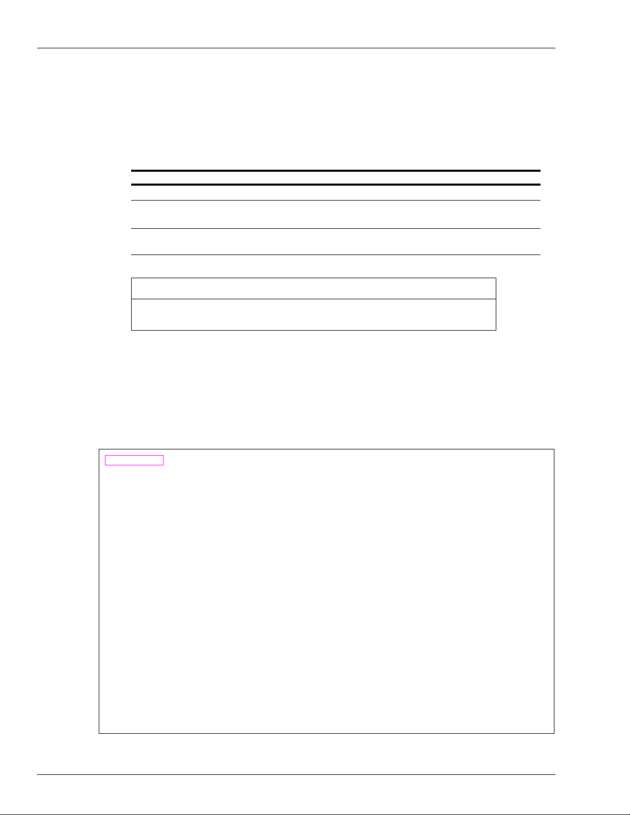
1 Press CAPS LOCK to activate the caps lock feature. Lock appears in the lower right-hand
corner of the screen.
2 Press CAPS LOCK and PRINT SCREEN simultaneously to enter SET-UP mode
(see Figure 1).
Figure 1: SET-UP Mode
Note: The status line at the bottom of the screen shows the current terminal settings.
Page 4 MDE-4974A Boundless® VT 520 Terminal and Okidata® Printer Setup for Gasboy® Fuel Management Systems · October 2012
Page 5
VT 520 Terminal Setup
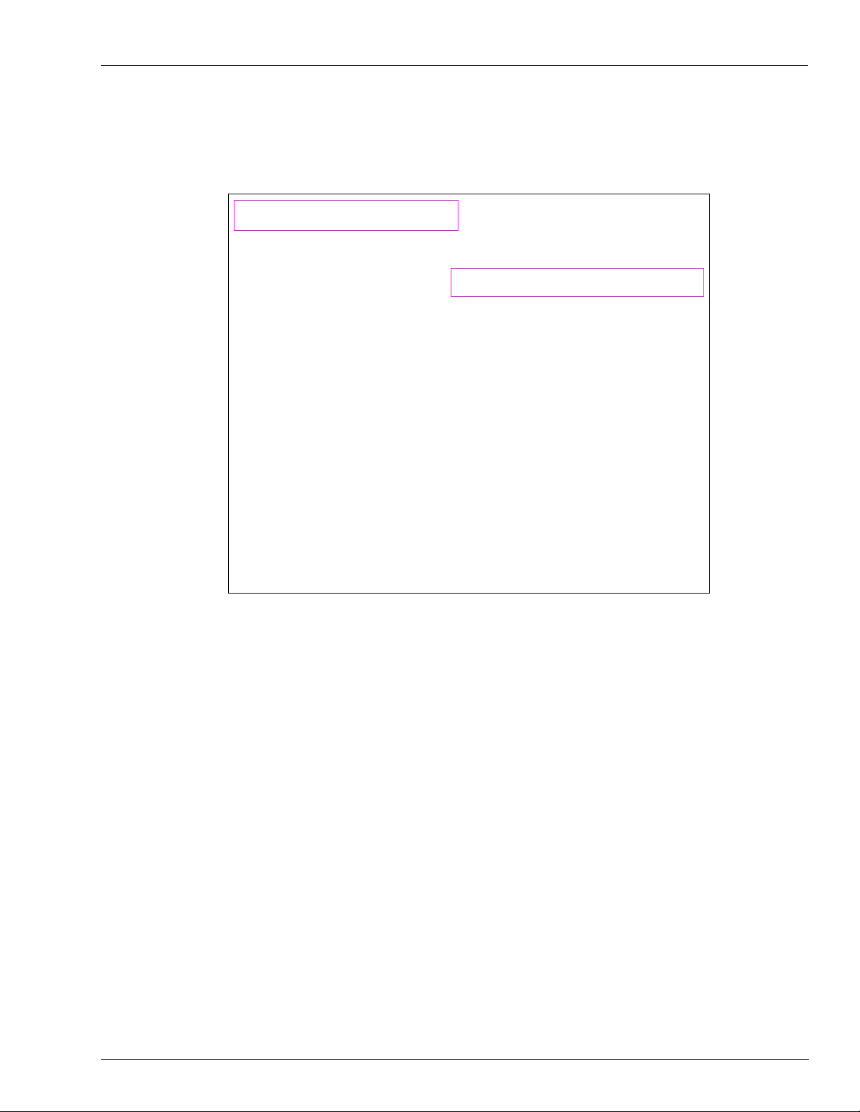
3 Use the arrow keys to highlight the Actions X Restore factory defaults option and press
ENTER to restore the factory default values (see Figure 2).
Figure 2: Restore Factory Defaults Op tion
MDE-4974A Boundless® VT 520 Terminal and Okidata® Printer Setup for Gasboy® Fuel Management Systems · October 2012 Page 5
Page 6

VT 520 Terminal Setup
4 Use the arrow keys to highlight the Display X Columns per page X 132 Columns option
and press ENTER to select the 132 column settings (see Figure 3).
Figure 3: 132 Columns Option
Note: The Columns per page setting of 132 may be changed to 80, if required. However, this
may cause transactions displayed on the screen (and on the Okidata printer) to wrap,
hindering readability.
Page 6 MDE-4974A Boundless® VT 520 Terminal and Okidata® Printer Setup for Gasboy® Fuel Management Systems · October 2012
Page 7

VT 520 Terminal Setup
5 Use the arrow keys to highlight the Display X Auto wrap option and press ENTER to
activate the auto wrap option (see Figure 4).
Figure 4: Auto Wrap Option
MDE-4974A Boundless® VT 520 Terminal and Okidata® Printer Setup for Gasboy® Fuel Management Systems · October 2012 Page 7
Page 8

VT 520 Terminal Setup
6 Use the arrow keys to highlight the Terminal type X Emulation mode option, select the
correct Emulation mode parameter, and press Enter to change the Emulation mode
(see Figure 5). The Emulation mode parameter must be set to:
• VT320 VT220
for Series 1000, FleetKey, TopKAT and “A” systems
• VT52 for CFN Series systems
Figure 5: Emulation Mode Option
Page 8 MDE-4974A Boundless® VT 520 Terminal and Okidata® Printer Setup for Gasboy® Fuel Management Systems · October 2012
Page 9

VT 520 Terminal Setup
7 Use the arrow keys to highlight the Communication X Port select option and press ENTER
(see Figure 6).
Figure 6: Port Select Option
MDE-4974A Boundless® VT 520 Terminal and Okidata® Printer Setup for Gasboy® Fuel Management Systems · October 2012 Page 9
Page 10

VT 520 Terminal Setup
8 Use the arrow keys to highlight the Print X comm3 option for session 1 and press ENTER
(see Figure 6 on page 9). Repeat the selection for all sessions. Use the arrow keys
OK and press ENTER.
to highlight
For connec
tions on the rear side of the terminal, see Figure 7.
Figure 7: Terminal Connections - Rear Side
COMM 1 Port
Parallel Port
COMM 2 Port
COMM 3 Port
Keyboard
Standard Wiring
From Gasboy System
RS-232 D Connector
~OR~
RS-232 GASBOY
Termin ation Box
~OR~
RS-422 GASBOY
Short Haul Modem
CRT Terminal (M07339B002)
and Keyboard (Q13181-02)
COM 1
25-pin D
MMJ to DB25F Adapter
(M07339B004)
COM 3
6-pin MMJ
Okidata ML 186 Printer with
Super-speed Serial
Interface (PA0373000)
Serial
25-pin D
MMJ to MMJ Cable
(M07339B003)
C03813 is the combination of
M07339B002, M07339B003,
M07339B004, and Q13181-02.
EIA 1:1 Cable (C04549)
Page 10 MDE-4974A Boundless® VT 520 Terminal and Okidata® Printer Setup for Gasboy® Fuel Management Systems · October 2012
Page 11

VT 520 Terminal Setup
9 Use the arrow keys to highlight the Printer X Print mode option (see Figure 8).
Figure 8: Print Mode Option
10 Set the Print mode parameter as follows:
Note: Ensure that you use the correct parameter setting for your
• If you have a Site Controller I, Islander I, S
ite Controller II*, or Islander II* software
software version.
version 1.0F or earlier, Series 1000, TopKAT or “A” System, then set the Print mode
parameter to Autoprint.
Note: In Autoprint, the Okidata printer acts as a logger and also prints everything
med in command mode. To temporarily suspend the output to the printer,
perfor
press CTRL and PRINT SCREEN simultaneously (the message line at the bottom
of the CRT screen toggles between Printer: Ready and Printer: Auto Print, when
these keys are pressed). Press CTRL and PRINT SCREEN simultaneously to
resume output to the printer.
MDE-4974A Boundless® VT 520 Terminal and Okidata® Printer Setup for Gasboy® Fuel Management Systems · October 2012 Page 11
Page 12

VT 520 Terminal Setup
• If you have a Site Controller II* or Islander II* software version 1.0F or later, then you
may set the Print mode parameter to Normal and configure the DIRECT PRINTOUT
CHANNEL in SYS_PAR to AUX-0.
Note: This parameter combination sends the direct printout to t
he Okidata logger and it is
not seen on the CRT screen. Any commands performed at the CRT are not logged
unless either output is directed to the logger (using ;>log with the command) or if
you press CTRL and PRINT SCREEN simultaneously to toggle the Main port
output to the logger (the message line at the bottom of the CRT screen toggles
between Printer: Ready and Printer: Auto Print, when these keys are pressed).
*If the Okidata printer is connected directly to the Site Contro
ller II or Islander II, then
configure the DIRECT PRINTOUT CHANNEL in SYS_PAR to the port to which the printer is
connected and for proper connection (RS-232), refer to Site Controller II or Islander II
Installation Manual.
11 Use the arrow keys to highlight the Printer X Serial print speed option. Select 9600 baud
and press ENTER (see Figure 9).
Figure 9: Serial Print Speed Option
Page 12 MDE-4974A Boundless® VT 520 Terminal and Okidata® Printer Setup for Gasboy® Fuel Management Systems · October 2012
Page 13

VT 520 Terminal Setup
12 If you have a Series 1000 software earlier to version 8.1, FleetKey software earlier to version
2.1, or “A” System software, use the arrow keys to highlight the Communication and Printer
options listed below and set the following parameter values:
• Communication X T
• Communication X T
• Communication X Re
• Printer X Serial print spe
• Printer X Tr
ansmit flow control parameter = NONE
• Printer X Receive flow contr
ransmit speed parameter = 1200
ransmit flow control parameter = NONE
ceive flow control parameter = NONE
ed parameter = 9600
ol parameter = NONE
For “A” Systems, set the following parameter values:
• Communication X W
• Communication X Parity parameter =
• Communication X St
13 Use the arrow keys to highlight the Save settings option and press ENTER to save the
ord size parameter = 7
Even
op Bits parameter = 2
terminal settings (see Figure 10).
Figure 10: Save Settings Option
14 Press CAPS LOCK and PRINT SCREEN simultaneously or highlight the Exit Set-Up
option and then press ENTER to exit SET-UP mode.
MDE-4974A Boundless® VT 520 Terminal and Okidata® Printer Setup for Gasboy® Fuel Management Systems · October 2012 Page 13
Page 14

Okidata 184/186 Printer Setup
Okidata 184/186 Printer Setup
T o prepare the Okidata 184/186 printer for operat ion with the Boundless VT 520 terminal and
your Gasboy Fuel Management System, proceed as follows:
1 Install and complete the setup of the printer as specified in the manufacturer’s setup
instructions.
2
Set up the switches as follows.
Switches SW1-1 through SW1-8
SW1 SET Function
SW1-1 ON Parity: Odd
SW1-2 ON Parity: Without
SW1-3 ON Data bits: 8
SW1-4 OFF Protocol: XON/XOFF (Series 1000 V8.1 or later, FleetKey V2.1 or later, CFN, or TopKAT)
ON Protocol: Ready/Busy (Series 1000 versions earlier
V2.1, and “A” systems)
SW1-5 ON Test select: Circuit
SW1-6 ON Mode select: Print
SW1-7 ON Busy line selection: DTR - Pin 20
SW1-8 ON Busy line selection: DTR - Pin 20
to V8.1, F
leetKey versions earlier to
Switches SW2-1 through SW2-3
Baud Rate* SW2-1 SW2-2 SW2-3
9600 OFF ON ON
2400 OFF OFF ON
1200 ON ON OFF
300 ON OFF OFF
*Any change made to the Baud Rate must also
be matched on th
X
Printer
Switches SW2-4 through SW2-8
SW2 SET Function
SW2-4 ON DSR output signal: Active
SW2-5 ON Buffer threshold: 32 bytes
SW2-6 OFF Busy signal timing: 1 sec (minimum)
SW2-7 ON DTR signal: Space after power on
SW2-8 OFF Not used
e Boundless ter
Serial print speed parameter.
minal setup,
Page 14 MDE-4974A Boundless® VT 520 Terminal and Okidata® Printer Setup for Gasboy® Fuel Management Systems · October 2012
Page 15

Printer Page Setup
To set up the printer page, proceed as follows:
1 Press SELECT to place the printer in offline mode. The SELECT light stops glowing.
2 Position the print head to the top of the paper and press TOF SET.
3 Press SELECT to place the printer in online mode. The SELECT light glows.
4 Press MODE until the light next to HSD glows.
5 Press PITCH until the light next to 17 glows.
Okidata 184/186 Printer Setup
Note: If transactions are less than 80 characters, then Pitch
(resulting in larger print).
may be set to a lower number
MDE-4974A Boundless® VT 520 Terminal and Okidata® Printer Setup for Gasboy® Fuel Management Systems · October 2012 Page 15
Page 16

Boundless® is a registered trademark of Boundless Technologies, Inc. CFN® is a registered trademark of FleetCor Technologies Operating
®
Company LLC. Gasboy
is a registered trademark of Gasboy International. Islander™ PLUS and TopKAT™ are trademarks of Gasboy
International. Okidata® is a registered trademark of Oki Electric Industry Co., Ltd.
© 2012 GASBOY
7300 West Friendly Avenue · Post Office Box 22087
Greensboro, North Carolina 27420
Phone 1-800-444-5529 · http://www.gasboy.com · Printed in the U.S.A.
MDE-4974A Boundless® VT 520 Terminal and Okidata® Printer Setup for Gasboy®
Fuel Management Systems · October 2012
 Loading...