

Page 1
INSTALLING THE VERIFONE PIN PAD ON THE PROFIT POINT
These instructions detail installing the Verifone Pin Pad option in a modular Profit Point. If you do not have a modular Profit
Point or if you are not sure, DO NOT proceed. Contact your service representative or Gasboy to verify the type of Profit
Point.
Pin Pad Kit for a modular Profit Point POS (C06981)
C01626 Pin Pad-Verifone
C06242 Cable Assy., 4-pos, 1:1 phone
C01271 PC Expansion Port Comm. PCB
C05991 Cable Assy., DB9F - to - DB9F, 1:1
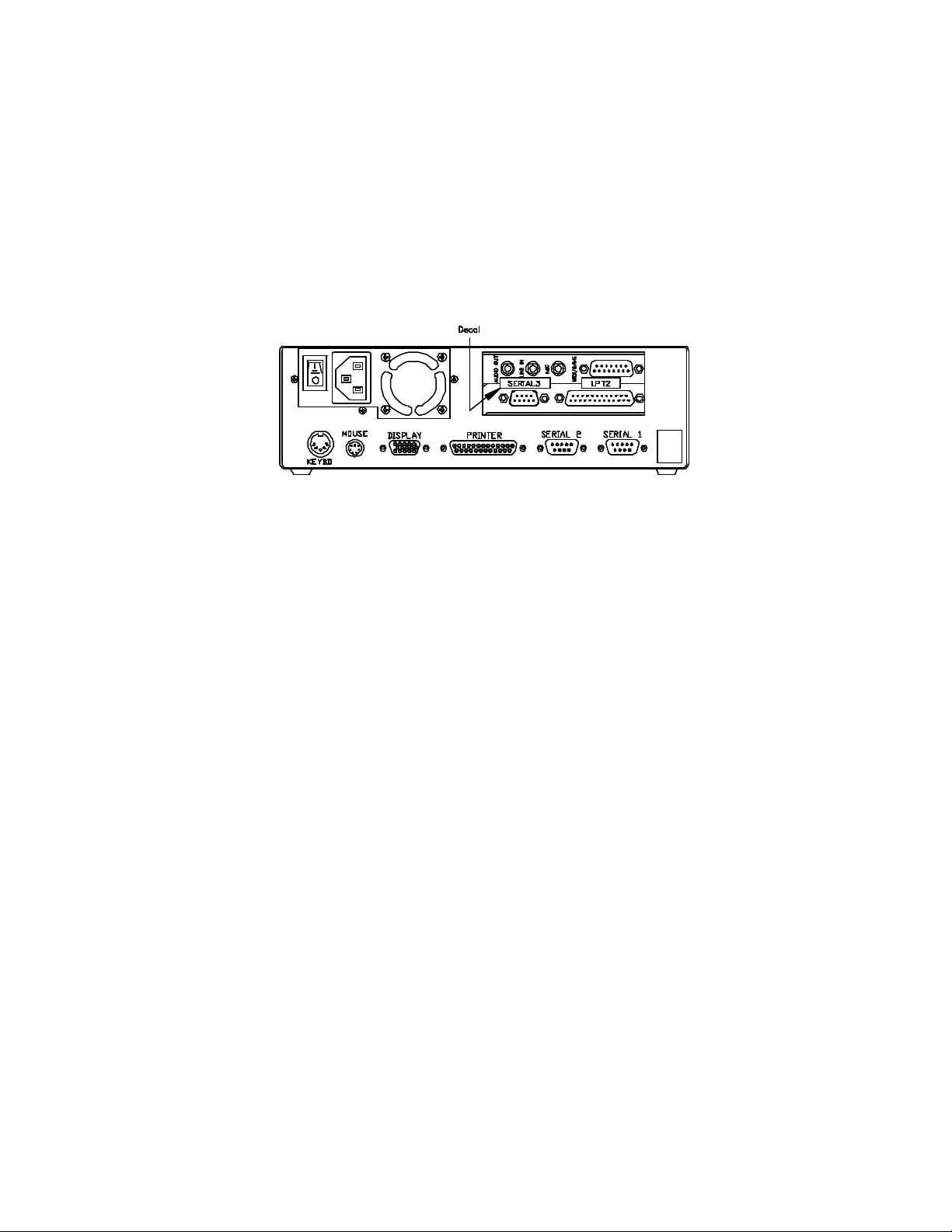
C09543 Decal, "SER3/SER4/LPT2" BLK-CLR
Static electricity can damage computer components and your Communication PCB. We recommend keeping your Comm.
PCB in its protective bag until you are ready to install it. We also recommend you observe antistatic precautions when
handling the PC and/or Comm. PCB.
Important: The Pin Pad connects to SERIAL3(COM3) on the back of the PC. If you already have a SERIAL3(COM3) port,
you do not need to install the expansion board and can skip to step 8.
1. Turn off the power to the PC and disconnect the cables from the back from the unit.
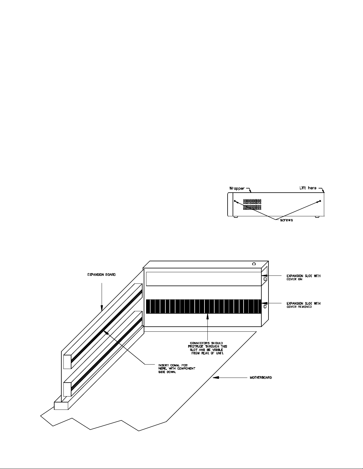
2. Remove four screws that hold the PC wrapper (2 on each side).
With the PC positioned so that you are facing the back where all
the connectors are, slide the inner part forward to remove it from the
outside wrapper, taking care not to pull the cables. It may be
necessary to gently lift up on the back of the wrapper to clear the
back of the PC.
3. Facing the front of the PC, at the left-hand side of the motherboard are two expansion slots. Unscrew and remove the
expansion slot cover retainer and remove the expansion covers. NOTE: Sound card may be present in one of the ISA
slots.
C35744 12/11/02
Page 2
4. The Comm. PCB has a jumper patch that needs to be checked before you install the board. Be sure Comm. PCB
jumper is jumpered for the following: Serial port 1 on PCB jumpered for Serial 3 (Com3/03E8), Serial port 2 on PCB
jumpered for Serial 4 (Com4/02E8), Parallel port jumpered for LPT2/0278 and NO interrupts (IRQs or INTs). Refer to
installation guide included with the Comm. PCB. This jumper patch will be on the underside of the board when it is
installed.
5. The ribbon cable and bracket assembly will not be needed. Insert the Comm PCB into the unused connector on the
expansion board (located to the left of the expansion slots) so that the connectors on the PCB protrude through the
expansion slot.
6. Install the expansion cover retainer and screw in, using screw that was removed (Step 3).
7. Reassemble Profit Point PC by replacing wrapper and four screws. Be careful not to pinch any cables or wires. Install
decals to the back of the expansion slots as shown.
8. Attach all cables to their previous connection on the back of the PC. Connect one end of the C05991 cable to SERIAL
3 (COM 3) port. Connect the other end to the POS distribution box SERIAL 3 port.
9. Attach one end of the 4-position phone cable (C06242) into the POS distribution box PIN PAD port and the other end
into the PIN pad.
10. Once installation is complete, verify the Profit Point and Site Controller are configured correctly. See the Profit Point
Reference Manual C35746, Hardware Configuration to see if the Profit Point is configured correctly. See the Site
Controller II Configuration Manual C09213 or Site Controller III Configuration Manual C09326, Console Configuration
to see if the Site Controller is configured correctly.
12/11/02 C35744
 Loading...