

Page 1
VAPOR RECOVERY KIT INSTALLATION INSTRUCTIONS
FOR MODEL 9120
This instruction sheet c overs the installation of the Model 9120, Vapor Recovery Kit (P/N 032628). Vapor recovery kit
does not include high hose retriever, hose, nozzle, swivel, and breakaway). You should have received the following:
Item Qty. P/N Description
1 1 042741 Discharge Assembly
2 1 041605 Panel, Right Side (VR)
3 1 028934 Grommet
4 1 003317 Boot, Nozzle (VR)
5 2 052857 Bolt 8-32 x 5/8
6 1 003719 Hook, Nozzle (VR)
Item Qty. P/N Description
7 1 049013 O-Ring
8 2 051805 Bolt 1/4-20 x 5/8
9 2 068891 Washer-Lock ¼
N/A 1 032627 Instruction Sheet
N/A 1 035282 Warning Sheet
Important: Read all instructions before beginning installation. Also, read and follow all precautions
regarding remote dispensers and pumps on the
Warnings and Safeguards
sheet, 035282, included in this
kit. Before performing any work which may produce sparks (e.g. drilling, use of power tools, etc.), remove
dispenser a safe distance from any flammable materials.
Installing Right Side Panel
1. Remove front door panel (key required).
2. Remove bezel assembly by unfastening two (2) Phillips head screws.
3. Remove rear door panel (key required).
4. Remove three (3) Phillips head screws and remove rear access panel.
5. Remove discharge pipe elbow.
6. Remove six (6) nuts from top cover assembly and remove top cover.
7. Remove three (3) screws from right side panel. Remove right side panel and discard.
8. Assemble new right side panel (item 2) with three (3) screws from Step 7.
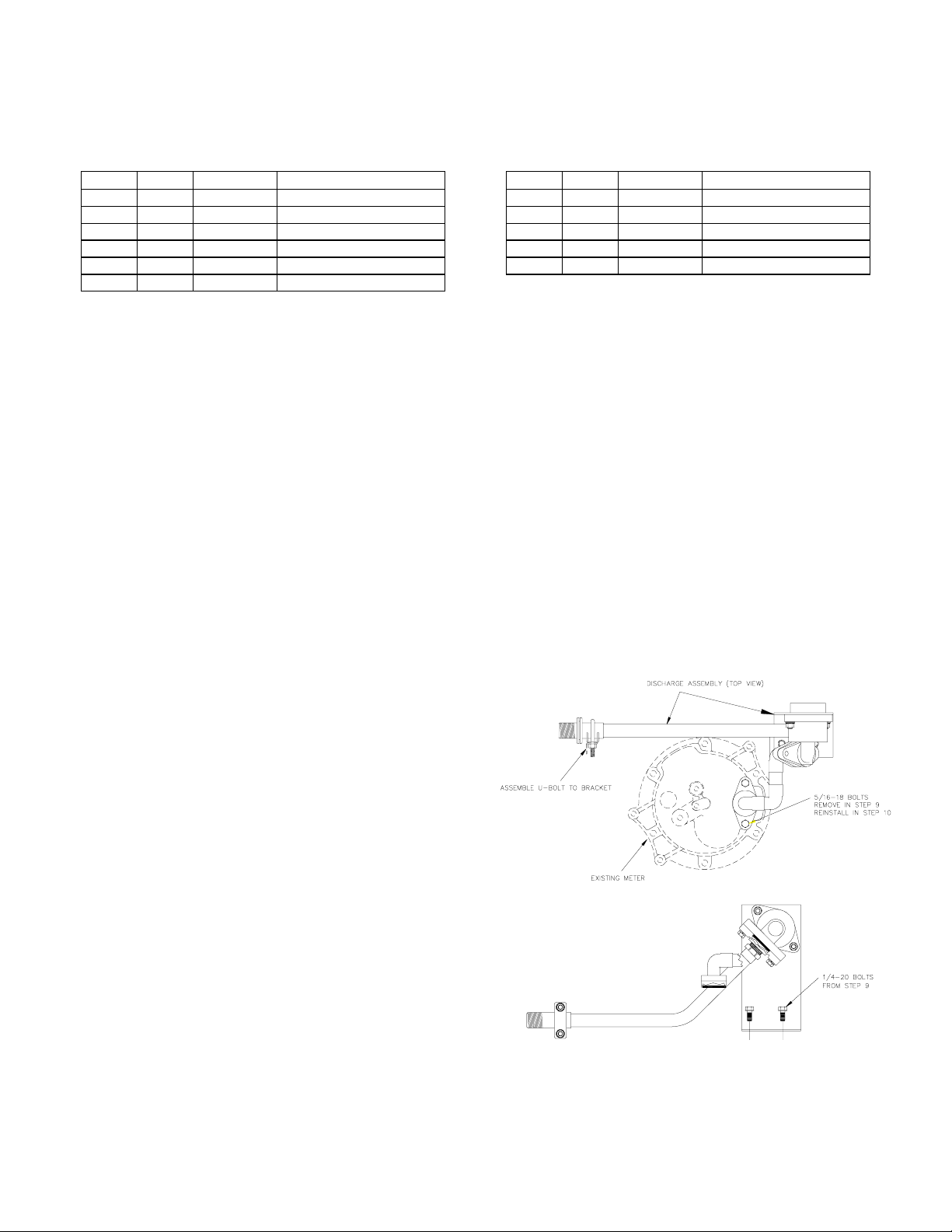
Installing Discharge Assembly
9. Remove two (2) 5/16-18 bolts from dis c harge c as ting
and two (2) 1/4-20 bolts from discharge clamp.
Remove discharge assembly from unit. NOTE:
Replace O-ring with supplied (item 7) O-ring. Apply
lithium based grease to O-ring.
10. Install new vapor recovery discharge assembly by
reinstalling two (2) 5/16-18 bolts and two (2) 1/4- 20
bolts from Step 9. N OTE: 1/4-20 bolts will secure
vapor recovery bracket to platform assembly.
11. Remove two (2) 8-32 screws from nozzle boot
casting and remove. Install vapor recovery nozzle
boot (item 4) with same screws.
12. Remove two (2) 1/4-20 bolts from nozzle hook
assembly and remove nozzle hook. Install vapor
recovery nozzle hook (item 6) with same 1/4-20
bolts.
13. Reinstall the dispenser top cover and panels by
following Steps 6 through 1.
032627 Rev. 0096 Page 1
Page 2
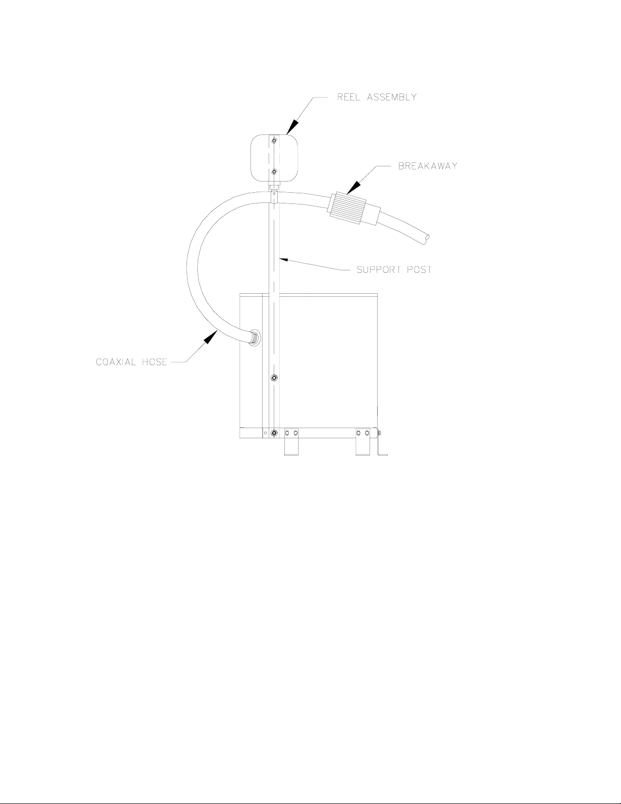
VAPOR RECOVERY W/HIGH HOSE RETRIEVER OVERVIEW
032627 Rev. 0096 Page 2
 Loading...