

Page 1
VAPOR ASSIST INSTALLATION INSTRUCTIONS
For Series 8753E, 8853E, 9153A, and 9853A Single and Twin Models
This instruction sheet cov ers the installation of the V apor Assist System for the models nam ed above. Assembly
and installation of a Vapor Assist System requires a kit containing the following:
Qty. P/N Description
1 017270 ¾” to 1” Bushing*
1 030424 ¾” Hardwall UL 1’ 9” hose
1 028930 ¾” Rubber Grommet
1 045802 Plate, Vapor Assist
1 047302 Pulley, 5/8” Bore, 2.6 Dia.
1 012163 Belt, A35
1 035282 Warnings and Safeguards
1 032169 Template
1 046631 Decal, Nozzle/Hose/Clamp
1 032170 Instruction Sheet
*Required for units with 1” discharge only.
Qty. P/N Description
1 N/A External Vapor Pump
1 N/A Pump Cover
1 N/A Bellowless Nozzle
1 N/A Breakaway
1 N/A Hose Retractor Clamp
1 N/A ¾” Elbow, 90°
2 Optional Thermoid Inverted Coaxial
Hose***
1 N/A Metal Mounting Plate **
2 N/A Locking Nuts
2 N/A Set Screws
**Discard item and use P/N 045802 plate noted at left.
***Must be a UL-Listed Inverted Coaxial Hose assembly.
1. Read all instructions before b eginnin g. Instal lation shou ld be don e accord ing to th e instruct ions on this sheet.
Also, read and follow all precautions regarding remote dispensers and pumps on the Warnings and
Safeguards sheet, 03 5282, included in the kit. SAFETY NOTE: Before drilling or performing any other
operation which may generate a spark, we recommend removing the dispenser and other pertinent
equipment a safe distance from the island.
2. Turn off power to the dispenser at the breaker and activate emergency shutoff valve.
3. On models 8853E/ ETW , 9153A/ATW , and 9853A/ATW, replace exist ing motor pulle y and V-belt wit h sup plied
pulley and V-belt. Model 8853ETW1 does not require this conversion.
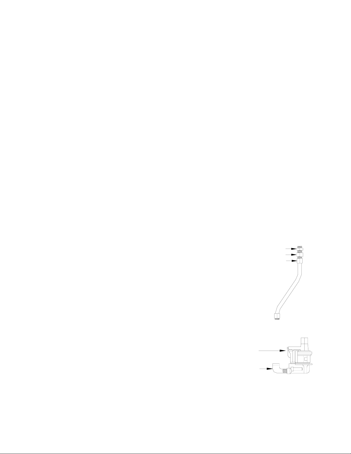
Assemble Product Jumper Hose
4. Use a UL-Classified gas- an d oil-resistant pipe com pound on all threads
when assembling these components. NOTE: All further references to
Bushing
Swivel
Jumper Hose
pipe compound in these instructions imply UL-classified pipe compound.
5. Assemble ¾”-1” bushing (017270) to ¾” jumper hose/swivel assembly
(030424).
6. Set aside.
Assembling Pumping Unit
7. Using pipe thread compound, attach ¾ x 90° elbow into product
connector on bottom of OPW pumping unit (Blackmer Model
VRFO, ID No. 2).
Pumping Unit
8. Thr ead set screws into the pump. Use a 1/8” Allen wrench to fully
tighten. Remove the protective vapor connection plug from the
vapor connection on the OPW pumping unit. Be careful not to
3/4" Elbow
allow any foreign matte r, such as dirt or metal shav ings to get
into the pump fitting. This could cause pump seizure and
malfunction.
9. G asboy recomm ends that you install a UL- Listed vapor line shear v alve, such as OPW 60VSP as part of the
new vapor line plumbing. Refer to instructions supplied with shear valve for installation details.
032170 Rev. 8279 Page 1
Page 2
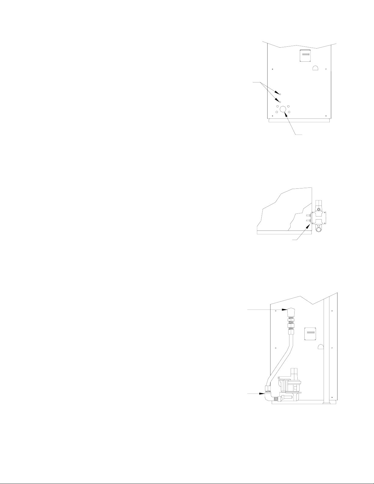
Mounting External Vapor Pump
10. Remove plastic plug (vapor connection opening) from side panel.
11. Refer to template (032169) f or instr uct ions on m arking an d dr illin g
two 5/16” diameter holes through both side panel and side frame.
Step 11
12. Replace plastic plug removed in Step 10 with rubber grommet
(028930).
Mount the Pump to the Dispenser
13. Position the OPW pump up to the dis penser. A lign the va por connecti on
of the OPW pumping un it with the side panel vapor open ing. Insert set
screws through mounting holes. From inside the dispenser, place
Gasboy metal plate (045802) over the screws and tighten locking nuts
onto screws.
Steps 10
& 12
Install Jumper Hose
14. Using pipe thread compound , thread product jumper hos e onto
90° elbow. Tighten with crescent wrench.
15. Using pipe thread compound, assemble jumper
hose/bushing/swivel assembly to existing dispenser discharge
and tighten.
Step 13
Step 15
Step 14
032170 Rev. 8279 Page 2
Page 3

Assemble Pump Cover
16. Measure the distance from the top of
the OPW pump to the dispens er island
surface. This measurement will
determine the height of the pump cover.
Steps 16 and 17
17. Mark this measurement on the pump
cover. Using a hacksaw, cut the pump
cover on the nearest r idge to meet this
dimension. Using a coping saw, cu t out
the edge section of the cover to allow
for elbow connection to the pump.
Cut Cover
Here
Pump
Height
Pump
Height
18. Loosen nuts inside dispenser . Place pump cover complete ly over the pump and tighten t he nuts inside the
dispenser with a 7/16” socket or box wrench. Do not overtighten locking nuts. Overtightening could
result in damage to the pump cover.
19. Measure ni pple length fr om pipe fitti ng to the UL-Lis ted interna l union half ( nto
Step 19
supplied). Be certain pipe thread engagement length is included in
measurement. Cut nipple and, using pipe compound, thread into pump.
Thread union half onto other end of nipple. Connect both union halves and
tighten.
Install Fueling Hose
20. Remove in verted coaxia l inlet protec tive cap from pump. Be careful n ot to allow any
foreign matter, such as dirt or metal shavings to get into the inverted coaxial
inlet. This could cause pump seizure and malfunction.
21. Lubricate the n ew inverted hos e threads and O -rings with greas e and thread the hose
onto the pump. Tighten the hose/pump connection. Do not use pipe thread
compound or Teflon tape on hose connection.
Steps 20 and 21
032170 Rev. 8279 Page 3
Page 4

22. With grease, lubricate the threads on the opposite end of the hose and
install the breakaway. Lubricat e and thread the second section of the
hose into the breakaway.
Steps 22 and 23
23. Thread OPW11VAI bellowless nozzle fitted with an efficiency
compliance device (ECD) onto the hose and tighten. NOTE: For
additional installa tion instructions, refer to specific procedures supplied
with the breakaway and nozzle.
Test System
24. Reset the emergency shutoff valve. Turn on the power to the pumping system.
25. Activate the dispens er and purge the air fr om the hose and pum p by d ispensing 1 to
1-1/2 gallons of gasoline into the authorized 5-gallon container. Upon completion,
return gasoline to the underground tank.
ECD
Check Performance
26. After the system has been completely installed, the performance of each dispensing hose point must be
measured by a trained technician with one of the following st and ar ds :
!
Latest revision of State of Califor nia Air Resources Board (CA RB), procedur e TP-201.5 – Determination
(by Volume Meter) of Air to Liquid Volume Ratio of Vapor Recovery Systems of Dispensing
Facilities. The measured A/L (Air/liquid) ratio should be between .9 and 1.1.
!
Latest revision of Stat e of Ca lif or ni a A ir Res o urc es Bo ard ( CA RB) , proc edur e T P- 201.5 A – Determination
(by Orifice Meter) of Air to Liquid Volume Ratio of Vapor Recovery Systems of Dispensing
Facilities. The measured A/L (Air/liquid) ratio should be between .9 and 1.1.
If the A/L reading does not fall between .9 and 1.1 it is not necessarily and indication of pump malfunction.
If the A/L ratio exceeds the spec ified r ange, chec k the entire vapor s ystem for poss ible leak s . If the A/L is
below the specified r ange, check the entire system for possible block ages. If A/L discrepancies per sist,
individual system components should be evaluated for proper functionality.
Important: Vent stack s must be o utfit ted w ith C ARB-approv ed pressure v acuum ven ts w it h a 3” wat er
column positive and 8” water column negative rating, such as the OPW523LP.
27. Replace decal on side panel For use only in UL Listed Interchangeable Service Station Type Hose
Nozzle Valve with the new decal (P/N 046631).
032170 Rev. 8279 Page 4
Page 5

28. If using a Gasboy High Hose Retriever, refer to the drawing below for final assembly overview.
NOTE: If you need a high hose retriever kit, order Gasboy part number 03266 0 for all units except 9800
Series. Order part number 032661 for 9800 Series units and complete as shown in the illustration.
HIGH HOSE RETRIEVER OVERVIEW
NOTE: Assemble supplied hose retractor clamp to high hose retriever reel assembly. Clamp should be
positioned so that hose does not touch the gr oun d when no zzl e is hung in no zzl e boo t.
032170 Rev. 8279 Page 5
 Loading...