

Page 1

Introduction
Purpose
This document provides installation instructions for the Card System Interface and
Electro-mechanical Totalizer Kits for Atlas™ Commercial Electronic Units:
• M06382K003 for RS-485 with Electro-mechanical Totalizers and DC Conduit
(New Bezel with Totalizer opening may be required).
• M06382K004 for Dual Units with Electro-mechanical Totalizers with Pulse-out
(Commercial Electronic Units Only).
Required Reading
Before installing a kit, the installer must read, understand, and follow:
• This manual
• NFPA 30A, The Automotive and Marine Service Station Code
• NFPA 70, The National Electric Code
• Applicable Federal, state, and local codes and regulations
MDE-4511B
Card System Interface and Electro-mechanical Totalizer
Retrofit Kits for Atlas™ Commercial Electronic Units
Installation Instructions
June 2011
Failure to do so may adversely affect the safe use and operation of the equipment.
Note: This kit must be installed by a Gasboy® Authorized Service Contractor (ASC) to
ensure warranty.
Table of Contents
Topic Page
Introduction
Important Safety Information
Installation
Completing the Installation
Required Tools
The following tools are required for the installation of the kit:
• Open-end Wrench Set
• Flat-tip Screwdriver
• Cross-tip Screwdriver
Related Documents
1
4
6
10
Document
Number
MDE-4255 Gasboy Warranty Policy St atement for USA and Canada • Gasboy Policy Documents
MDE-4511B Retrofit Kits for Atlas™ Electro-mechanical and Commercial Electronic Units Installation Instructions · June 2011 Page 1
Title GOLD Library
• Domestic Warranty & Owner’s Manuals
Page 2

Introduction
Parts List
M06382K003 for RS-485 with Electro-mechanical Totalizers and
DC Conduit (Commercial Electronic Units Only)
Note: New Bezel with Totalizer opening may be required.
Item Description Part Number Quantity
1 PCA, RS-485 Interface M06725A001 1
2 Totalizer, Electro-mechanical M00455A002 2
3 Screw, Thread Forming Metric M00417B224 4
4 Cable Tie Q10178-05 2
5 Assembly, Pulse-out Conduit and Cable M05189A002 1
6 Washer, Conduit Seal N23760-04 2
7 Faced Unilet Reducer K49827 1
8 Union, Conduit Q10016-04 1
9 Bracket, J-Box DC Shield M05235B001 1
10 Screw, Thread Forming Metric M00417B113 1
11 Card System Interface and Electro-mechanical
Totalizer Retrofit Kits for Atlas Electro-mechanical
and Commercial Electronic Units Installation
Instructions
MDE-4511 1
M06382K004 for Dual Units with Electro-mechanical Totalizers with
Pulse-out (Commercial Electronic Units Only)
Item Description Part Number Quantity
1 PCA, Atlas 9800 Pulse-out Totalizer M06587A001 1
2 Totalizer, Electro-mechanical M00455A002 2
3 Screw, Metric, M4 X 8 M00417B224 4
4 Cable Tie Q10178-05 2
5 Assembly, Pulse-out Conduit and Cable M05189A002 1
6 Washer, Conduit Seal N23760-04 2
7 Faced Unilet Reducer K49827 1
8 Union, Conduit Q10016-04 1
9 Bracket, J-Box DC Shield M05235B001 1
10 Screw, Metric, M4 X 8 M00417B113 1
11 Card System Interface and Electro-mechanical
Totalizer Retrofit Kits for Atlas Electro-mechanical
and Commercial Electronic Units Installation
Instructions
MDE-4511 1
Page 2 MDE-4511B Retrofit Kits for Atlas™ Electro-mechanical and Commercial Electronic Units Installation Instructions · June 2011
Page 3

Introduction
M06301K009 for Dual Units with Electro-mechanical Totalizers with
Pulse-out (Retail Electronic Units Only)
Item Description Part Number Quantity
1 Totalizer, Electro-mechanical M00455A004 2
2 Cable Tie Q10178-05 2
3 Cable, Totalizer M05586A001 1
4 Decal Arrow N23140-01 2
5 Card System Interface and Electro-mechanical
T ot alizer Retrofit Kits for Atlas Electro-mechanical
and Commercial Electronic Units Installation
Instructions
MDE-4511 1
M06301K010 for Dual Units with Electro-mechanical Totalizers without
Pulse-out (Retail Electronic Units Only)
Item Description Part Number Quantity
1 Totalizer, Electro-mechanical M00455A003 2
2 Cable Tie Q10178-05 2
3 Cable, Totalizer M04889A001 1
4 Decal Arrow N23140-01 2
5 Card System Interface and Electro-mechanical
Totalizer Retrofit Kits for Atlas Electro-mechanical
and Commercial Electronic Units Installation
Instructions
MDE-4511 1
Abbreviations and Acronyms
Term Description
ASC Authorized Service Contractor
CPU Central Processing Unit
DC Direct Current
NFPA National Fire Protection Association
OSHA Occupational Safety and Hazard Association
PCA Printed Circuit Assembly
Warranty
For information on warranty, refer to MDE-4255 Gasboy Warranty Policy Statement for USA
and Canada. If you have any warranty-related questions, contact Gasboy’s Warranty
Department at its Greensboro location.
MDE-4511B Retrofit Kits for Atlas™ Electro-mechanical and Commercial Electronic Units Installation Instructions · June 2011 Page 3
Page 4
Important Safety Information
Important Safety Information
This section introduces the hazards and safety precautions
associated with installing, inspecting, maintaining, or
servicing this product. Before performing any task on this
product, read this safety information and the applicable
sections in this manual, where additional hazards and safety
precautions for your task will be found. Fire, explosion,
electrical shock, or pressure release could occur and cause
death or serious injury, if these safe service procedures are
not followed.
Preliminary Precautions
You are working in a potentially dangerous environment of
flammable fuels, vapors, and high voltage or pressures. Only
trained or authorized individuals knowledgeable in the related
procedures should install, inspect, maintain, or service this
equipment.
Emergency Total Electrical Shut-Off
The first and most important information you must know is
how to stop all fuel flow to the pump/dispenser and island.
Locate the switch or circuit breakers that shut off all power to
all fueling equipment, dispensing devices, and Submerged
Turbine Pumps (STPs).
!
WARNING
!
The EMERGENCY STOP, ALL STOP, and
PUMP STOP buttons at the cashier’s station
WILL NOT shut off electrical power to the
pump/dispenser. This means that even if you
activate these stops, fuel may continue to flow
uncontrolled.
Read the Manual
Read, understand, and follow this manual and any other
labels or related materials supplied with this equipment. If you
do not understand a procedure, call a Gasboy Authorized
Service Contractor or call the Gasboy Service Center at
1-800-444-5529. It is imperative to your safety and the safety
of others to understand the procedures before beginning
work.
Follow the Regulations
Applicable information is available in National Fire Protection
Association (NFPA) 30A; Code for Motor Fuel Dispensing
Facilities and Repair Garages, NFPA 70; National Electrical
Code (NEC), Occupational Safety and Hazard Association
(OSHA) regulations and federal, state, and local codes. All
these regulations must be followed. Failure to install, inspect,
maintain, or service this equipment in accordance with these
codes, regulations, and standards may lead to legal citations
with penalties or affect the safe use and operation of the
equipment.
Replacement Parts
Use only genuine Gasboy replacement parts and retrofit kits
on your pump/dispenser. Using parts other than genuine
Gasboy replacement parts could create a safety hazard and
violate local regulations.
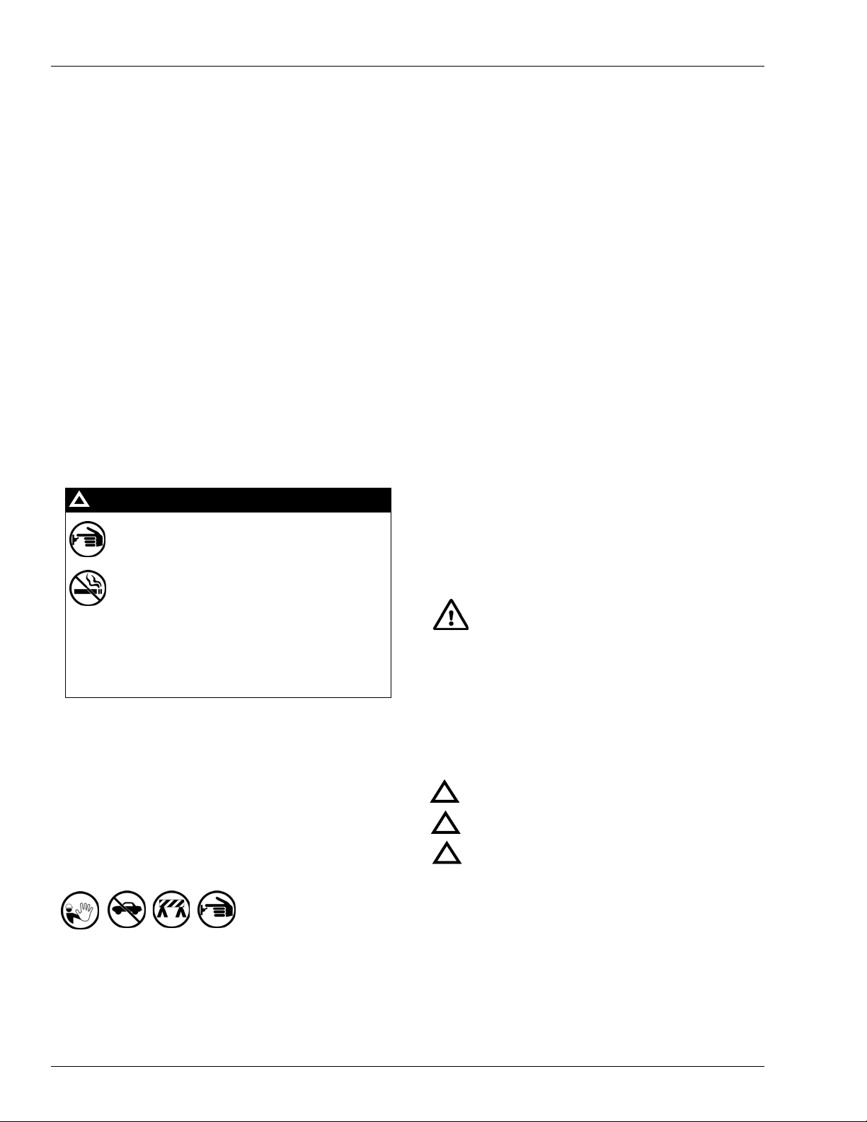
Safety Symbols and Warning Words
This section provides important information about warning
symbols and boxes.
Alert Symbol
You must use the TOTAL ELECTRICAL
SHUT-OFF in the case of an emergency and
not the console’s ALL STOP and PUMP STOP
or similar keys.
Total Electrical Shut-Off Before Access
Any procedure that requires access to electrical components
or the electronics of the dispenser requires total electrical
shut off of that unit. Understand the function and location of
this switch or circuit breaker before inspecting, installing,
maintaining, or servicing Gasboy equipment.
Evacuating, Barricading, and Shutting Off
Any procedure that requires access to the pump/dispenser or
STPs requires the following actions:
• An evacuation of all unauthorized persons and vehicles
from the work area
• Use of safety tape, cones, or barricades at the affected
unit(s)
• A total electrical shut-off of the affected unit(s)
This safety alert symbol is used in this manual and
on warning labels to alert you to a precaution which must be
followed to prevent potential personal safety hazards. Obey
safety directives that follow this symbol to avoid possible
injury or death.
Signal Words
These signal words used in this manual and on warning
labels tell you the seriousness of particular safety hazards.
The precautions below must be followed to prevent death,
injury, or damage to the equipment:
DANGER: Alerts you to a hazard or unsafe practice
!
which will result in death or serious injury.
WARNING: Alerts you to a hazard or unsafe practice
!
that could result in death or serious injury.
CAUTION with Alert symbol: Designates a hazard or
!
unsafe practice which may result in minor injury.
CAUTION without Alert symbol: Designates a hazard
or unsafe practice which may result in property or
equipment damage.
Working With Fuels and Electrical Energy
Prevent Explosions and Fires
Fuels and their vapors will explode or burn, if ignited. Spilled
or leaking fuels cause vapors. Even filling customer tanks will
cause potentially dangerous vapors in the vicinity of the
dispenser or island.
Page 4 MDE-4511B Retrofit Kits for Atlas™ Electro-mechanical and Commercial Electronic Units Installation Instructions · June 2011
Page 5

Important Safety Information
No Open Fire
Open flames from matches, lighters, welding torches,
or other sources can ignite fuels and their vapors.
No Sparks - No Smoking
Sparks from starting vehicles, starting, or using power tools,
burning cigarettes, cigars, or pipes can also ignite fuels and
their vapors. Static electricity, including an electrostatic
charge on your body, can cause a spark sufficient to ignite
fuel vapors. Every time you get out of a vehicle, touch the
metal of your vehicle, to discharge any electrostatic charge
before you approach the dispenser island.
Working Alone
It is highly recommended that someone who is capable of
rendering first aid be present during servicing. Familiarize
yourself with Cardiopulmonary Resuscitation (CPR) methods,
if you work with or around high voltages. This information is
available from the American Red Cross. Always advise the
station personnel about where you will be working, and
caution them not to activate power while you are working on
the equipment. Use the OSHA Lockout/Tagout procedures. If
you are not familiar with this requirement, refe r to this
information in the service manual and OSHA documentation.
Working With Electricity Safely
Ensure that you use safe and established practices in
working with electrical devices. Poorly wired devices may
cause a fire, explosion, or electrical shock. Ensure that
grounding connections are properly made. Take care that
sealing devices and compounds are in place. Ensure that you
do not pinch wires when replacing covers. Follow OSHA
Lockout/T agout requirements. Station employees and service
contractors need to understand and comply with this program
completely to ensure safety while the equipment is down.
Hazardous Materials
Some materials present inside electronic enclosures may
present a health hazard if not handled correctly. Ensure that
you clean hands after handling equipment. Do not place any
equipment in the mouth.
!
WARNING
The pump/dispenser contains a chemical known to the
State of California to cause cancer.
In an Emergency
Inform Emergency Personnel
Compile the following information and inform emergency
personnel:
• Location of accident (for example, address, front/back of
building, and so on)
• Nature of accident (for example, possible heart attack, run
over by car, burns, and so on)
• Age of victim (for example, baby, teenager, middle-age,
elderly)
• Whether or not victim has received first aid (for example,
stopped bleeding by pressure, and so on)
• Whether or not a victim has vomited (for example, if
swallowed or inhaled something, and so on)
WARNING
!
Gasoline ingested may cause unconsciousness
and burns to internal organs.
Do not induce vomiting.
Keep airway open.
Oxygen may be needed at scene.
Seek medical advice immediately.
WARNING
!
Gasoline inhaled may cause unconsciousness
and burns to lips, mouth, and lungs.
Keep airway open.
Seek medical advice immediately.
WARNING
!
Gasoline spilled in eyes may cause burns to eye
tissue.
Irrigate eyes with water for approximately
15 minutes.
Seek medical advice immediately.
WARNING
!
Gasoline spilled on skin may cause burns.
Wash area thoroughly with clear water.
Seek medical advice immediately.
IMPORTANT: Oxygen may be needed at scene if gasoline
has been ingested or inhaled. Seek medical advice
immediately.
WARNING
!
Lockout/Tagout
Lockout/Tagout covers servicing and maintenance of
The pump/dispenser contains a chemical known to the
State of California to cause birth defects or other
reproductive harm.
machines and equipment in which the unexpected
energization or start-up of the machine(s) or equipment or
release of stored energy could cause injury to employees or
personnel. Lockout/Tagout applies to all mechanical,
hydraulic, chemical, or other energy, but does not cover
electrical hazards. Subpart S of 29 CFR Part 1910 - Electrical
Hazards, 29 CFR Part 1910.333 contains specific
Lockout/Tagout provi sion for electrical hazards.
MDE-4511B Retrofit Kits for Atlas™ Electro-mechanical and Commercial Electronic Units Installation Instructions · June 2011 Page 5
Page 6

Installation
Installation
Preparing for Installation
Before you begin, obtain permission from the manager/owner to remove power from the unit
and then remove power using normal procedures. Follow the OSHA lockout/tagout safety
procedures.
Ensure that you have the proper kit for the dispenser to be retrofitted.
1 Unlock and remove the doors from both sides of the un it using the pr oper key for the unit. Place
the doors in a safe place to prevent damage or scratches.
2 Remove the two screws securing the dial enclosure assembly and remove the assembly using a
cross-tip screwdriver.
Note: Retain the screws for replacing assembly after installation.
3 Remove the two screws (located above the display) at Side 1 of the unit and pull the display
cover forward using a cross-tip screwdriver. The cover will pivot down in a horizontal position
allowing access to the electronics section of the unit.
Note: Retain the screws for replacing the assembly after installation.
Installing the Pulse-out/RS-485 Board (Commercial Unit Only)
To install the Pulse-out/RS-485 Board, proceed as follows:
1 Locate the correct board for your application in the kit. The board type in your kit is determined
as follows:
• M06382K003 kit has the RS-485 Board (M06725A001) (New Bezel with Totalizer opening
may be required).
• M06382K004 kit has the Pulse-out Board (M06587A001).
Note: For description of kits, refer to “Introduction” on page 1.
2 Connect the new board P2 Connector to P8 Connector of the Main Central Processing
Unit (CPU) Board (see Figure 1 on page 7).
Page 6 MDE-4511B Retrofit Kits for Atlas™ Electro-mechanical and Commercial Electronic Units Installation Instructions · June 2011
Page 7

Installation
3 Align the two holes in the corners of the Printed Circuit Assembly (PCA) with the two
standoffs (already mounted to the shelf) and secure the board with two screws (M00417B224).
Figure 1: Mounting the Pulse-out/RS-485 Board (Commercial Unit Only)
Mounting Screws (M00417B224)
P2 and P8 Connectors
Installing the Electro-mechanical Totalizer
To install the electro-mechanical totalizer in a commercial or a retail unit and to connect the
cables, proceed as follows:
1 On the back of the bezel face at the opening for the totalizer, remove the two nuts securing the
plastic glass plate (with the black tedlar decal) using the appropriate wrench and remove the
plate.
Note: Retain the nuts for remounting.
2 If installing totalizer on a commercial unit, remove the black tedlar decal from the plastic glass
plate. Remount and secure the plate with the two nuts removed in step
3 Locate the Totalizer (M00455A002) in the kit and install on the display support bracket in
position as shown in
Figure 2 on page 8. Position the screw in the totalizer in the slot in the
support bracket (as a locator for the totalizer).
4 Secure the totalizer to the support bracket with the Cable Tie (Q10178-05).
5 If working with a dual unit, repeat steps 1 through 3 for the other side of the unit.
6 If connecting cables on a commercial unit (for block diagram, see Figure 5 on page 11):
a Connect the Side A (J-Box side) totalizer cable to the totalizer A (P802 Connector) on the
Pulse-out/RS-485 board.
b Connect the Side B totalizer cable to the totalizer B (P803 Connector) on the
Pulse-out/RS-485 board.
c Locate the existing cable (M05108A001) connected to P2 on Power Supply and connect
J804 Connector to P804 on totalizer.
1.
MDE-4511B Retrofit Kits for Atlas™ Electro-mechanical and Commercial Electronic Units Installation Instructions · June 2011 Page 7
Page 8

Installation
7 If connecting cables on a retail unit with Pulse-out (for block diagram, see Figure 6 on
page 11):
a Locate the cable (M05586A001) in the kit.
b Connect P1501 Connector to the totalizer on Side A of the unit.
c Connect P1504 Connector to the totalizer on Side B of the unit.
d Connect J202 Connector to P202 on Pump Controller PCA (T20011-G1).
e Locate the existing cable (M05108A001) connected to P2 on the power supply and
connect J804 Connector to P804 on the totalizer.
8 If connecting cables on a retail unit without Pulse-out (for block diagram, see Figure 7 on
page 12):
a Locate the cable (M04889A001) in the kit.
b Connect J922A Connector to the totalizer on Side A of the unit.
c Connect J922B Connector to the totalizer on Side B of the unit.
d Connect J406 Connector to PP406 on Pump Interface PCA (T18994-G1).
e Locate the existing cable (M05108A001) connected to P2 on the power supply and
connect J804 Connector to P804 on the totalizer.
Figure 2: Mounting Position for the Electro-mechanical Totalizer
Slot in Support Bracket
Display Support Bracket
Mounting “Shelf”
Adding Decals (Dual Units Only)
Decals must be added to designate which totalizer is associated with which hose on the unit.
The totalizer on the Side A of the unit is associated with the hose on Side 1 of the unit and the
totalizer on the Side B of the unit is associated with the hose on Side 2 of the unit. The
following figure indicates the side locations:
Side B
Side 1
Junction Box
Side 2
Side A
Page 8 MDE-4511B Retrofit Kits for Atlas™ Electro-mechanical and Commercial Electronic Units Installation Instructions · June 2011
Page 9

Installation
On both sides of the unit, place a N23140-01 decal (arrow), which is part of the kit, on the
bezel face to the left of the totalizer opening. Orient the arrow pointing to the left (away from
the totalizer opening). On Side A of the unit the arrow is pointing toward Side 1. On Side B of
the unit, the arrow is pointing toward Side 2.
Installing the DC Conduit (Commercial Unit Only)
Note: If you already have a DC conduit installed and the harness does not match the harness
provided with this kit, then remove the DC conduit and install the DC conduit supplied
with this kit.
To install the DC conduit, proceed as follows:
1 Remove the cover mounting screws and the cover at the junction box.
Note: Retain screws for remounting the cover.
2 Insert and tighten the Reducer (K49827) in the opening (location of the opening is shown in
Figure 3).
Note: As a reminder, the conduit threads engage a minimum of five threads.
Figure 3: Junction Box Connections
Reducer (K49827)
Union (Q10016-04)
Shield (M05235B001)
Shield Mounting Screw
(M00417B224)
3 Insert the Conduit Union (Q10016-04) in the reducer installed in step 2.
Note: When performing steps 4 through 8 on page 10, ensur e tha t you hold the conduit in
place when mounting washers until it is connected to the union at the junction box.
4 Route the straight end of the conduit through the lower barrier plate. For conduit and washer
placement for steps
5 Place a washer on the conduit (in the air gap).
6 Continue routing the conduit through the upper barrier plate.
MDE-4511B Retrofit Kits for Atlas™ Electro-mechanical and Commercial Electronic Units Installation Instructions · June 2011 Page 9
4 through 6, see Figure 4 on page 10.
Page 10

Completing the Installation
7 Place a washer on the conduit on the top of the upper barrier plate.
Figure 4: Routing Conduit Through Barrier Plates
Washer
Upper Barrier Plate
Air Gap
Washer
Screw
(Securing Washer)
8 At the lower end of the conduit, connect to the union mounted in the junction box. Ensure that
Lower Barrier Plate
the Cable Assembly (M05189A002) cables are properly routed into the junction box.
9 Secure the washer to the lower barrier plate using a screw (M00417B224). Place the screw
from the under side of the lower barrier plate (see
Figure 4). Hold the washer securely in place
against the barrier plate when mounting and tightening the screw.
Note: There are two screw holes in the washer. However, use only one screw to secure. Place
the screw in the hole behind the conduit (looking from the Side A of the unit-side with
the junction box).
10 At the upper end of the conduit, connect the cable (M05189A001) connector to P1 on the
Pulse-out/RS-485 PCA (see
11 Place the shield (M05235B001) in the junction box and secure with the screw (M00417B113)
(see
Figure 3 on page 9).
12 Connect the four wires at the junction box.
Figure 5 on page 11).
13 Remount the junction box cover and secure with screws that were removed in step 1 on page 9.
Completing the Installation
1 After the installation is complete, proceed as follows:
a Remount the dial enclosure assemblies using the screws removed in step 2 on page 6.
b Remount the doors on both sides of the unit.
c Secure doors with the keylocks.
2 Inform the manager/owner that the unit can be returned back to service.
Page 10 MDE-4511B Retrofit Kits for Atlas™ Electro-mechanical and Commercial Electronic Units Installation Instructions · June 2011
Page 11

Completing the Installation
Figure 5: M05193 K-pump Partial Block Diagram (Showing CPU and Pulse-out PCA)
(Commercial Electronic Units Only)
Figure 6: M04228 K-pump Partial Block Diagram (With Pulse-out) (Retail Units Only)
MDE-4511B Retrofit Kits for Atlas™ Electro-mechanical and Commercial Electronic Units Installation Instructions · June 2011 Page 11
Page 12

Completing the Installation
Figure 7: M04885 K-pump Partial Block Diagram (Without Pulse-out) (Retail Units Only)
Atlas™ is a trademark of Gasboy International. Gasboy® is a registered trademark of Gasboy International.
© 2011 GASBOY
7300 West Friendly Avenue · Post Office Box 22087
Greensboro, North Carolina 27420
Phone 1-800-444-5529 · http://www.gasboy.com · Printed in the U.S.A.
MDE-4511B Retrofit Kits for Atlas™ Electro-mechanical and Commercial Electronic Units
Installation Instructions · June 2011
 Loading...