

Page 1

TopKAT™ PLUS
Installation Manual
MDE-5013C
Page 2

Computer Programs and Documentation
Gasboy, Greensboro, is an ISO 9001:2000 registered facility.
Underwriters Laboratories (UL):
UL File# Products listed with UL
MH4314
All dispensers and self-contained pumping
units
MH10581 Key con t r o l u n i t , M o d e l G K E - B S e r i e s
Card reader terminals, Models 1000, 1000P
Site Controller, Model 2000S CFN Series
Data entry terminals, Model TPK-900 Series
Fuel Point Reader System
National Conference of Weights and Measures (NCWM) - Certificate of Compliance (CoC):
Gasboy pumps and dispensers are evaluated by NCWM under the National Type Evaluation Program (NTEP). NCWM has issued the following CoC:
CoC# Product Model # CoC# Product Model # CoC# Product Model #
95-179 Dispenser
9100 Retail Series, 8700
Series, 9700 Series
91-019 Dispenser
9100 Commercial
Series
05-002 Atlas
8700K, 8800K,
9100K, 9200K, 9800K
95-136 Dispenser 9800 Series 91-057 Controller
1000 Series FMS,
2000S-CFN Series
California Air Resources Board (CARB):
Executive Order # Product
G-70-52-AM Balance Vapor Recovery
G-70-150-AE VaporVac
Non-registered trademarks
Consola
™
Infinity
™
Islander™ PLUS
Registered trademarks
ASTRA
®
Atlas
®
Fuel Point
®
Gasboy
®
Keytrol
®
Slimline
®
Additional US and foreign trademarks pending.
Other brand or product names shown may be trademarks or registered trademarks of their respective holders.
Federal Communications Commission (FCC) Warning
All Gasboy computer programs (including software on diskettes and within memory chips) and documentation are copyrighted by, and shall remain the property of, Gasboy. Such
computer programs and documents may also contain trade secret information. The duplication, disclosure, modification, or unauthorized use of computer programs or
documentation is strictly prohibited, unless otherwise licensed by Gasboy.
This equipment has been tested and found to comply with the limits for a Class A digital device pursuant to Part 15 of the FCC Rules. These limits are designed to provide
reasonable protection against harmful interference when the equipment is operated in a commercial environment. This equipment generates, uses, and can radiate radio frequency
energy, and if not installed and used in accordance with the instruction manual, may cause harmful interference to radio communications. Operation of this equipment in a
residential area is likely to cause harmful interference in which case the user will be required to correct the interference at his own expense. Changes or modifications not expressly
approved by the manufacturer could void the user’s authority to operate this equipment.
Approvals
Trademarks
This document is subject to change without notice.
This document is subject to change without notice.
http://www.gasboy.com
E-mail: literature@gasboy.com · Internet: http://www.gasboy.com
2014 GASBOY. All Rights Reserved.
2015 GASBOY. All Rights Reserved.
Page 3

Table of Contents
Table of Contents
1 – Introduction 1-1
Purpose. . . . . . . . . . . . . . . . . . . . . . . . . . . . . . . . . . . . . . . . . . . . . . . . . . . . . . . . . . . . . . . . . . . . . . . . 1-1
Intended Users . . . . . . . . . . . . . . . . . . . . . . . . . . . . . . . . . . . . . . . . . . . . . . . . . . . . . . . . . .
Description. . . . . . . . . . . . . . . . . . . . . . . . . . . . . . . . . . . . . . . . . . . . . . . . . . . . . . . . . . .
System Overview. . . . . . . . . . . . . . . . . . . . . . . . . . . . . . . . . . . . . . . . . . . . . . . . . . . . . . . . .
TopKAT PLUS System. . . . . . . . . . . . . . . . . . . . . . . . . . . . . . . . . . . . . . 1-2
Remote Web Access . . . . . . . . . . . . . . . . . . . . . . . . . . . . . . . . . . . . . . . 1-2
Head Office . . . . . . . . . . . . . . . . . . . . . . . . . . . . . . . . . . . . . . . . . . . . . . 1-3
Restrictions and Limits. . . . . . . . . . . . . . . . . . . . . . . . . . . . . . . . . . . . . . 1-3
System Workflow Example . . . . . . . . . . . . . . . . . . . . . . . . . . . . . . . . . . 1-4
TopKAT PLUS Structure . . . . . . . . . . .
Main Components . . . . . . . . . . . . . . . . . . . . . . . . . . . . . . . . . . . . . . . . . 1-4
Electrical Setup . . . . . . . . . . . . . . . . . . . . . . . . . . . . . . . . . . . . . . . . . . . . . . . . . . . . . . . .
Available Configurations . . . . . . . . . . . . . . . . . . . . . . . . . . . . . . . . . . . . . . . . . . . . . . . . . . . . .
General . . . . . . . . . . . . . . . . . . . . . . . . . . . . . . . . . . . . . . . . . . . . . . . . 1-12
Optional Printer . . . . . . . . . . . . . . . . . . . . . . . . . . . . . . . . . . . . . . . . . . 1-12
Dispensers . . . . . . . . . . . . . . . . . . . . . . . . . . . . . . . . . . . . . . . . . . . . . . 1-12
Security and Protection . . . . . . . . . . . . . . . . . . . . . . . . . . . . . . . . . . . . . . . . . . . . . . . . . . . . . .
General . . . . . . . . . . . . . . . . . . . . . . . . . . . . . . . . . . . . . . . . . . . . . . . . 1-13
Authorization Security . . . . . . . . . . . . . . . .
Network Security . . . . . . . . . . . . . . . . . . . . . . . . . . . . . . . . . . . . . . . . . 1-13
Maintenance Security. . . . . . . . . . . . . . . . .
Housing . . . . . . . . . . . . . . . . . . . . . . . . . . . . . . . . . . . . . . . . . . . . . . . . . . . . . . . . . . . . .
Specifications . . . . . . . . . . . . . . . . . . . . . . . . . . . . . . . . . . . . . . . . . . . . . . . . . . . . . . . . .
Standards . . . . . . . . . . . . . . . . . . . . . . . . . . . . . . . . . . . . . . . . . . . . . . . . . . . . . . . . . . . .
Communication Standards. . . . . . . . . . . . . . . . . . . . . . . . . . . . . . . . . . 1-14
Security Standards. . . . . . . . . . . . . . . . . . . . . . . . . . . . . . . . . . . . . . . . 1-14
Using This Manual. . . . . . . . . . . . . . . . . . . . . . . . . . . . . . . . . . . . . . . . . . . . . . . . . . . . . . . .
Related Documents. . . . . . . . . . . . . . . . . . . . . . . . . . . . . . . . . . . . . . . . . . . . . . . . . . . . . . . . .
Abbreviations and Acronyms. . . . . . . . . . . . . . . . . . . . . . . . . . . . . . . . . . . . . . . . . . . . . . . . . . .
. . . . . . . . . . . . . . . . . . . . . . . . . . . . . . . . . . . . . . . . . . . . . . . . 1-4
. . . . . . . . . . . . . . . . . . . . . 1-13
. . . . . . . . . . . . . . . . . . . . . 1-13
. . . . . . . . 1-1
. . . . . . . . . . . 1-1
. . . . . . . . 1-2
. . . . . . . . . 1-11
. . . . . 1-12
. . . . . 1-13
. . . . . . . . . . 1-13
. . . . . . . . . 1-14
. . . . . . . . . 1-14
. . . . . . . 1-15
. . . . . 1-15
. . . . 1-16
2 – Important Safety Information 2-1
3 – TopKAT PLUS Installation Procedures 3-1
General . . . . . . . . . . . . . . . . . . . . . . . . . . . . . . . . . . . . . . . . . . . . . . . . . . . . . . . . . . . . . . . . . . . . . . . . 3-1
Installation Specifications . . . . . . . . . . . . . . . . . . .
General . . . . . . . . . . . . . . . . . . . . . . . . . . . . . . . . . . . . . . . . . . . . . . . . . 3-1
Precautions and Safety Notes . . . . . . . . . . . . . . . . . . . . . . . . . . . . . . . . 3-1
Types of Cables . . . . . . . . . . . . . . . . . . . . . . . . . . . . . . . . . . . . . . . . . . . 3-2
Types of TopKAT PLUS Units . . . . . . . . . . . . . . . . . . . . . . . . . . . . . . . . 3-2
Head Assembly Dimensions . . . .
Pedestal Dimensions . . . . . . . . . . . . . . . . . . . . . . . . . . . . . . . . . . . . . . . 3-3
Conduits . . . . . . . . . . . . . . . . . . . . . . . . . . . . . . . . . . . . . . . . . . . . . . . . . . . . . . . . . . . .
General . . . . . . . . . . . . . . . . . . . . . . . . . . . . . . . . . . . . . . . . . . . . . . . . . 3-4
Conduit Requirements . . . . . . . . . . . . . . . . . . . . . . . . . . . . . . . . . . . . . . 3-4
Barrier Plate Conduit Penetration . . . . . . . . . . . . . . . . .
Sealing Conduits . . . . . . . . . . . . . . . . . . . . . . . . . . . . . . . . . . . . . . . . . . 3-6
Safety Distance . . . . . . . . . . . . . . . . . . . . . . . . . . . . . . . . . . . . . . . . . . . 3-6
MDE-5013C TopKAT™ PLUS Installation Manual · February 2015 Page i
. . . . . . . . . . . . . . . . . . . . . . . . . . . . . . . . . . . . . . . 3-1
. . . . . . . . . . . . . . . . . . . . . . . . . . . . . 3-2
. . . . . . . . . . . 3-4
. . . . . . . . . . . . . . . . . . . . . . . . . . . . . . . . . . . 3-5
Page 4

Table of Contents
TopKAT PLUS Pedestal Mounting Instructions . . . . . . . . . . . . . . . . . . . . . . . . . . . . . . . . . . . . . . . . . .3-7
Parts List. . . . . . . . . . . . . . . . . . . . . . . . . . . . . . . . . . . . . . . . . . . . . . . . .3-7
Connections to TopKAT PLUS - Pedestal Mounted
Wiring . . . . . . . . . . . . . . . . . . . . . . . . . . . . . . . . . . . . . . . . . . . . . . . . . . . . . . . . . . . . . .
Types of Wiring . . . . . . . . . . . . . . . . . . . . . . . . . . . . . . . . . . . . . . . . . . .3-11
Wiring Requirements. . . . . . . . . . . . . . . . . . . . . . . . . . . . . . . . . . . . . . .3-11
Types of Cables . . . . . . . . . . . . . . . . . . . . . . . . . . . . . . . . . . . . . . . . . .3-11
Field Wiring Requirements (LAN/WAN) . . . . . . . . . . . . . . . . . . . . . . . .3-12
AC Power Connection. . . . . . . . . . . . . . . . . . . . . . . . . . . . . . . . . . . . . .3-13
Mechanical Pump - Wiring . . . . . . . . . . . . . . . . . . . . . . . . . . . . . . . . . . . . . . . . . . . . . . . . . . . . .
General . . . . . . . . . . . . . . . . . . . . . . . . . . . . . . . . . . . . . . . . . . . . . . . . .3-14
Terminal Block - Pin-out Connections for Mechanical Pumps
Mechanical Pump - Required Connections. . . . . . . . . . . . . . . . . . . . . .3-15
Single Suction Pump . . . . . . . . . . . . . . . . . . . . . . . . . . . . . . . . . . . . . . . . . . . . . . . . . . . . . . .
Mechanical Pump - Pulser Connections. . . . . . . . . . . . . . . . . . . . . . . . . . . . . . . . . . . . . . . . . . . . . . .3
RS-485 Electronic - TopKAT PLUS on Gasboy 9800 Atlas
(Factory Installed) .
Electronic Pump Wiring - TopKAT PLUS on Pedest
Mechanical Pulser. . . . . . . . . . . . . . . . . . . . . . . . . . . . . . . . . . . . . . . . .3-22
Electronic Pump - Wiring Description (Pedestal Mount)
General . . . . . . . . . . . . . . . . . . . . . . . . . . . . . . . . . . . . . . . . . . . . . . . . .3-23
RS-485 Electronic Pump. . . . . . . . . . . . . . . . . . . . . . . . . . . . . . . . . . . .3-24
Electronic Pump - Wiring Description (Atlas Mounted TopKAT PLUS)
Post-installation Checklist. . . . . . . . . . . . . . . . . . . . . . . . . . . . . . . . . . . . . . . . . . . . . . . . . . .
Completion Checklist . . . . . . . . . . . . . . . . . . . . . . . . . . . . . . . . . . . . . .3-26
TopKAT PLUS Setup . . . . . . . . . . . . . . . . . . . . . . . . . . . . . . . . . . . . . . . . . . . . . . . . . . . . . . .
Manager Tag . . . . . . . . . . . . . . . . . . . . . . . . . . . . . . . . . . . . . . . . . . . . . . . . . . . . . . . . . . . .
Performing a Test Transaction . . . . . . . . . . . . . . . . . . . . . . . . . . . . . . .3-27
Disabling Test Transaction Option . . . . . . . . . . . . . . . . . . . . . . . . . . . .3-29
Opening Printer Front Panel . . . . . . . . . . . . . . . . . . . . . . . . . . . . . . . . .3-29
Units . . . . . . . . . . . . . . . . . . . . . . . . . . . . . . . . . .3-9
. . . . . . . . . . .3-11
. . . .3-14
. . . . . . .3-14
. . . . . .3-18
-19
. . . . . . . . . . . . . . . . . . . . . . . . . . . . . . . . . . . . . . . .3-20
al . . . . . . . . . . . . .3-21
. . . . . . . . . . . . . . . . . . . . . . . . . . . . . . . . . . .3-23
. . . . . . . . . . . . . . . . . . . . . . .3-25
. . . . . . .3-26
. . . . . .3-27
. . . . . . .3-27
4 – Printer 4-1
General. . . . . . . . . . . . . . . . . . . . . . . . . . . . . . . . . . . . . . . . . . . . . . . . . . . . . . . . . . . . . . . . . . . . . . . . .4-1
Description . . . . . . . . . . . . . . . . . . . . . . . . . . . . . . . . . . . . . . . . . . . . . . . . . . . . . . . . . .
Main Components . . . . . . . . . . . . . . . . . . . . . . . . . . . . . . . . . . . . . . . . . . . . . . . . . . . . . . . . .
Printer Connector Pin-out. .
Housing . . . . . . . . . . . . . . . . . . . . . . . . . . . . . . . . . . . . . . . . . . . . . . . . . . . . . . . . . . . .
Indicators . . . . . . . . . . . . . . . . . . . . . . . . . . . . . . . . . . . . . . . . . . . . . . . . . . . . . . . . . . .
Protection . . . . . . . . . . . . . . . . . . . . . . . . . . . . . . . . . . . . . . . . . . . . . . . . . . . . . . . . . . .
Specifications . . . . . . . . . . . . . . . . . . . . . . . . . . . . . . . . . . . . . . . . . . . . . . . . . . . . . . . . . .
Setting Printing Parameters . . . . . . . . . . . . . . . . . . . . . . . . . . . . . . . . . . . . . . . . . . . . . . . . . .
Replacement - Installation . . . . . . . . . . . . . . . . . . . . . . . . . . . . . . . . . . . . . . . . . . . . . . . . . . .
Paper Roll Replacement. . . . . . . . . . . . . . . . . . . . . . . . . . . . . . . . . . . . . . . . . . . . . . . . . . . . .
Cleaning Printer . . . . . . . . . . . . . . . . . . . . . . . . . . . . . . . . . . . . . . . . . . . . . . . . . . . . . . . .
Troubleshooting . . . . . . . . . . . . . . . . . . . . . . . . . . . . . . . . . . . . . . . . . . . . . . . . . . . . . . . . . .
Thermal Paper Storage . . . . . . . . . . . . . . . . . . . . . . . . . . . . . . . . . . . . . . . . . . . . . . . . . . . . .
. . . . . . . . . . . . . . . . . . . . . . . . . . . . . . . . . . . . . . . . . . . . . . . . . . . . . . . . .4-5
Jumpers Configuration . . . . . . . . . . . . . . . . . . . . . . . . . . . . . . . . . . . . . .4-7
Parameters for Printing . .
Cutter . . . . . . . . . . . . . . . . . . . . . . . . . . . . . . . . . . . . . . . . . . . . . . . . . . .4-8
Printing Status Report. . . . . . . . . . . . . . . . . . . . . . . . . . . . . . . . . . . . . . .4-8
Installing Printer . . . . . . . . . . . . . . . . . . . . . . . . . . . . . . . . . . . . . . . . . . .4-9
Installing Cable . . . . . . . . . . . . . . . . . . . . . . . . . . . . . . . . . . . . . . . . . . .4-10
General . . . . . . . . . . . . . . . . . . . . . . . . . . . . . . . . . . . . . . . . . . . . . . . . .4-10
Replacing Paper Roll . . . . . . . . . . . . . . . . . . . . . . . . . . . . . . . . . . . . . .4-10
Releasing Jammed or Crumpled Paper . . . . .
. . . . . . . . . . . . . . . . . . . . . . . . . . . . . . . . . . . .4-8
. . . . . . . . . . . . . . . . . . .4-13
. . . . . . . . . . . .4-2
. . . . . . .4-3
. . . . . . . . . . . .4-6
. . . . . . . . . . . .4-6
. . . . . . . . . . . .4-6
. . . . . . . . . .4-6
. . . . . . .4-7
. . . . . . .4-9
. . . . . .4-10
. . . . . . . . .4-13
. . . . . . .4-13
. . . . . .4-14
Page ii MDE-5013C TopKAT™ PLUS Installation Manual · February 2015
Page 5

Table of Contents
5 – Maintenance 5-1
General . . . . . . . . . . . . . . . . . . . . . . . . . . . . . . . . . . . . . . . . . . . . . . . . . . . . . . . . . . . . . . . . . . . . . . . . 5-1
Troubleshooting. . . . . . . . . . . . . . . . . . . . . . . . . . . . . . . . . . . . . . . . . . . . . . . . . . . . . . . . . .
TopKAT PLUS Troubleshooting. . . . . . . . . . . . . . . . . . . . . . . . . . . . . . . 5-2
OrPT Troubleshooting . . . . . . . . . . . . . . . .
Printer Troubleshooting . . . . . . . . . . . . . . . . . . . . . . . . . . . . . . . . . . . . . 5-6
Communication Troubleshooting . . . . . . . . . . . . . . . . . . . . . . . . . . . . . . 5-7
Safety Reinforcements. . . . . . .
Cleaning. . . . . . . . . . . . . . . . . . . . . . . . . . . . . . . . . . . . . . . . . . . . . . . . . 5-9
. . . . . . . . . . . . . . . . . . . . . . . . . . . . . . . 5-8
. . . . . . . . . . . . . . . . . . . . . . 5-5
. . . . . . . . 5-1
Glossary Glossary-1
FuelOmat Glossary . . . . . . . . . . . . . . . . . . . . . . . . . . . . . . . . . . . . . . . . . . . . . . . . . . . . . . . . . Glossary-1
Communication Glossary . . . . . . . . . . . . . . . . . . . . . . . . . . . . . . . . . . . . . . . . . . . . . . . . . . . . Glo
ssary-1
Appendix A: Wiring Diagrams A-1
Appendix B: Parts List B-1
Appendix C: TopKAT PLUS Parts Illustrated C-1
Index Index-1
MDE-5013C TopKAT™ PLUS Installation Manual · February 2015 Page iii
Page 6

Table of Contents
This page is intentionally left blank.
Page iv MDE-5013C TopKAT™ PLUS Installation Manual · February 2015
Page 7

Purpose Introduction
1 – Introduction
Purpose
This manual provides installation instructions for TopKAT™ PLUS, the complete station
automation solution in a dispenser-mounted compact box. The system must be installed in the
factory as described in this manual to ensure its reliability and proper operation.
This manual includes a general and functional
components, installation requirements, and procedures.
Intended Users
This manual is intended for Authorized Service Contractors (ASCs) of TopKAT PLUS and its
components. It is also intended for the factory and island electricians.
Description
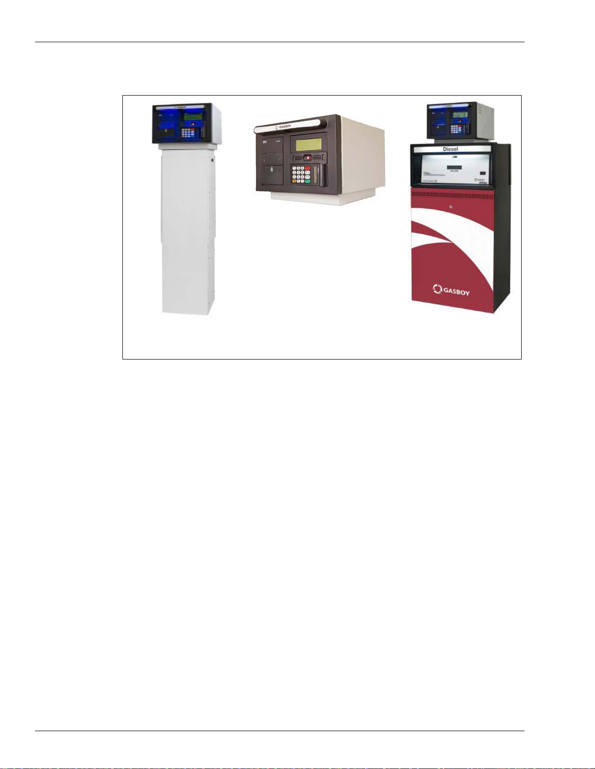
T o pKAT PLUS is a fuel control and data acquisition system. The system is self-contained in a
forecourt compatible and weather-resistant cabinet installed on top of Gasboy
mounted on a post.
TopKAT PLUS (see Figu
small home base gas stations. TopKAT PLUS provides the central function of site controller
adequate for a maximum of two nozzles in a single dispenser. It also fulfills other essential
services on the island such as driver identification system, transaction data storage, and so on.
Its ergonomic design, as well as its user-friendly operating program, enables fast and accurate
service for the driver in the refueling site.
description of the product, its main
®
dispensers or
re 1-1 on page 1-2) is a core component in Gasboy’s solution for
TopKAT PLUS is equipped with the Outdoor Payment Terminal (OrPT), a payment terminal
and communication receptacle. The payment terminal is equipped with an alphanumeric
Liquid Crystal Display (LCD) and a keyboard to interface with the client. This enables
T opKAT PLUS to support all common refueling identification devices such as magnetic cards,
®
contactless Radio Frequency Identification (RFID) tags (also known as MIFARE
keypad entry.
MDE-5013C TopKAT™ PLUS Installation Manual · February 2015 Page 1-1
tags), and
Page 8
Introduction System Overview
Post Mounted Unit for Mechanical and
Electronic Dispensers
TopKAT PLUS mounted on an
Atlas
®
9800 Dispenser
(i)
(ii)
(iii)
TopKAT PLUS - General View
Figure 1-1: TopKAT PLUS - General View
System Overview
TopKAT PLUS System
TopKAT PLUS is an innovative product that enables refueling in home base gas stations for
fleet authorized vehicles or drivers. T opKAT PLUS electronically locks the dispenser nozzles,
thereby ensuring that only appropriately authorized vehicles and plants receive the required
fuel. The system also ensures accurate recording of each transaction (see Figure 1-2
on page 1-3).
The heart of the home base station solution is the SiteOmat automation software. SiteOmat
ns on an embedded operating system on the Orpak
ru
embedded hardware platform designed to survive the harsh gas station environment. It uses a
solid state flash disk and Real Time Clock (RTC) with backup along with surge suppressors
for transient and noise immunity. The system also includes power failure recovery
mechanisms.
Remote Web Access
Remote web-based capabilities for monitoring, management, and maintenance are available.
A standard PC with Microsoft
locally or remotely (secured). A special management software is not required, thanks to the
built-in web server technology integrated into the station controller and the large variety of
communication links supported.
™
Controller Unit (OrCU). OrCU is an
®
Internet Explorer® is used for management of the site either
Page 1-2 MDE-5013C TopKAT™ PLUS Installation Manual · February 2015
Page 9
System Overview Introduction
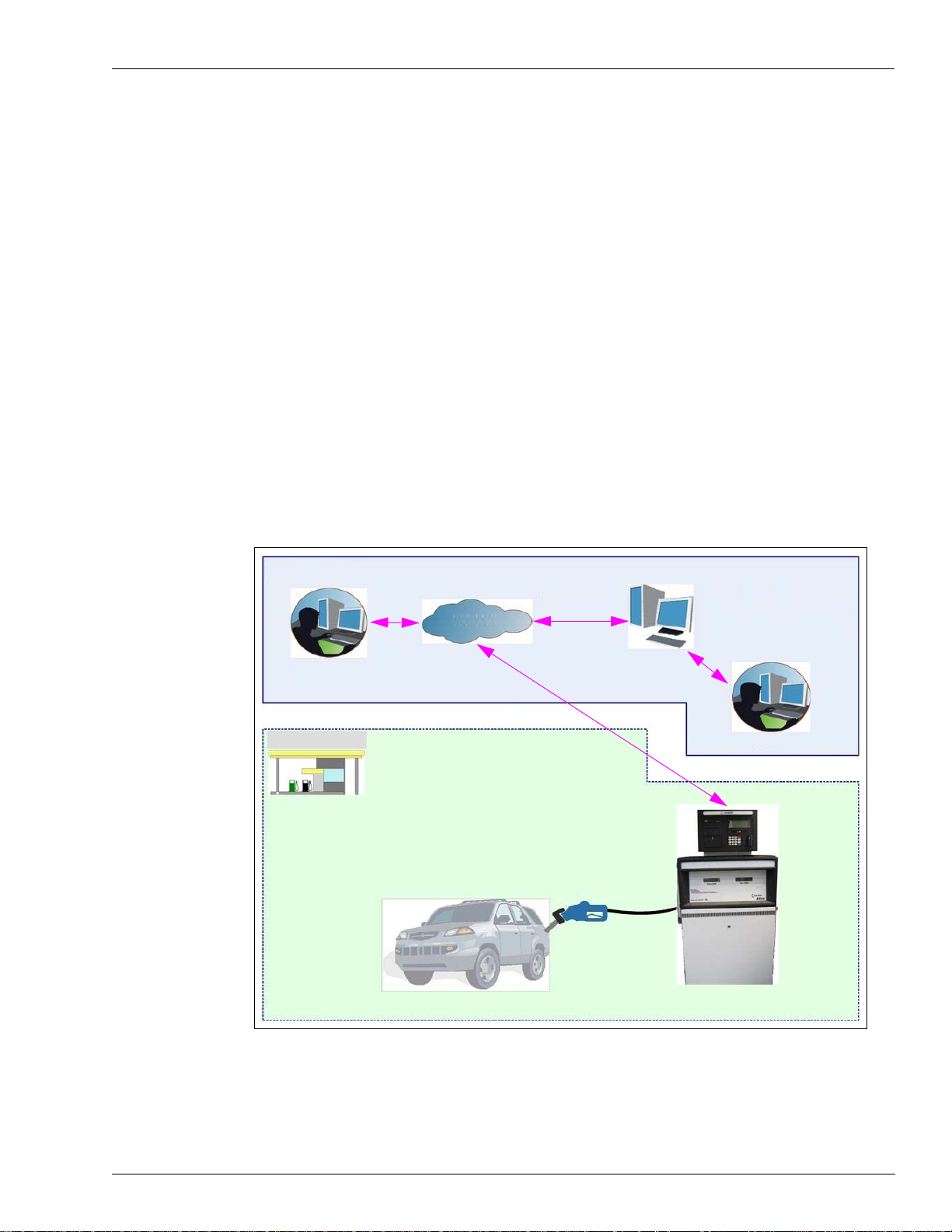
Head Office
-Site Manager
- Technician
Management &
Reporting
Fleet Manager
Home Base
Network
Fleet Head Office Web Server
- Issuing Vehicle Identification
- Authorizing Vehicle Identification
- Setting Limits & Restrictions
- Reporting and Management
- Fuel Management (Optional)
Head Office
Centralized management is provided by the optional Fleet Head Office (FHO) and Fuel
Management Software Server. The head office system consolidates the data from multiple
sites and generates reports, including exception reports. It also enables control of the limits
and restrictions placed on the various fleet vehicles. In addition, authorized fleet personnel are
able to login remotely and are always in control. Head office enables authorized users to
control and manage wet stock inventory on all stations including orders, deliveries, and
reports.
Restrictions and Limits
Control of fleet’s fuel expenses can be maximized by defining limits (day, week, month),
maximum number of refueling (day, week, month), and setting restrictions (days of the week,
fuel type, stations, time intervals). In cases where the system is configured for multiple sites,
the centralized FHO must synchronize the data between all sites so that the limits can be
applied to a whole system rather than to an individual site. In case of communication failure,
the specific site is able to refuel for a predefined grace period (parameter) using the most
recent limits stored in its database.
Figure 1-2: TopKAT PLUS in Home Base Station - General Configurat ion Diagram
MDE-5013C TopKAT™ PLUS Installation Manual · February 2015 Page 1-3
Page 10

Introduction TopKAT PLUS Structure
System Workflow Example
Following example depicts the operational workflow for self-service at the home base station:
Refueling Scenario with Magnetic Cards
A motorist stops for fuel at the station. His authorization device for the fueling transaction is a
magnetic card. The client swipes the card through the magnetic card reader on the payment
panel.
The magnetic card information is read and sent to the s
and approval. The client lifts the nozzle and inserts it in the car inlet. On approval, the fueling
transaction starts, at the end of which the transaction data is kept internally. The data is
transferred to the fuel head office for future billing.
The client may add more data to the transaction, by manually entering the information using
the payment panel keyboard. After the refueling is completed, the motorist replaces the nozzle
to pump.
The motorist may print a transaction ticket from the TopKAT PLUS printer (optional).
TopKAT PLUS Structure
Main Components
Following is a short description of the TopKAT PLUS main sub-assemblies:
OrCU
OrCU is a complete forecourt controller with its own embedded operating system. The unit
consists of an embedded hardware platform with a solid state flash hard disk, RTC with
backup, along with surge suppressors for transient and noise immunity.
ite controller (OrCU) for authentication
®
OrCU features two separate and isolated networks (TCP/IP over Ethernet
links the TopKAT PLUS system components. The second network is intended for external
remote communication (head office and third-party systems). This network is protected by
Secured Socket Layer (SSL) security.
Page 1-4 MDE-5013C TopKAT™ PLUS Installation Manual · February 2015
). One network
Page 11
TopKAT PLUS Structure Introduction
OrCU includes a built-in server for web access through an Internet browser (Internet
Explorer).
Figure 1-3: OrCU
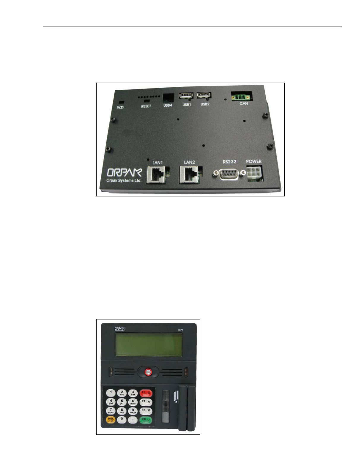
OrPT Panel
The OrPT consists of a payment panel and communication equipment. The panel is equipped
with an alphanumeric LCD (graphic LCD, optional) and a keyboard to interface with the
client. The payment panel is equipped with several authorization options such as magnetic
card reader and RFID tag reader. These authorization tools enable TopKA T PLUS to accept all
common authorization methods such as credit cards, magnetic cards, and contactless tags.
tho
OrPT supports keyboard entry for au
such as odometer, engine hours, vehicle plate number, and PIN code.
The OrPT panel is connected to the site controller (OrCU) through a Local Area Network
[LAN (Ethernet)] link.
Figure 1-4: OrPT Panel
rization, and other parameters’ input from the user
MDE-5013C TopKAT™ PLUS Installation Manual · February 2015 Page 1-5
Page 12
Introduction TopKAT PLUS Structure
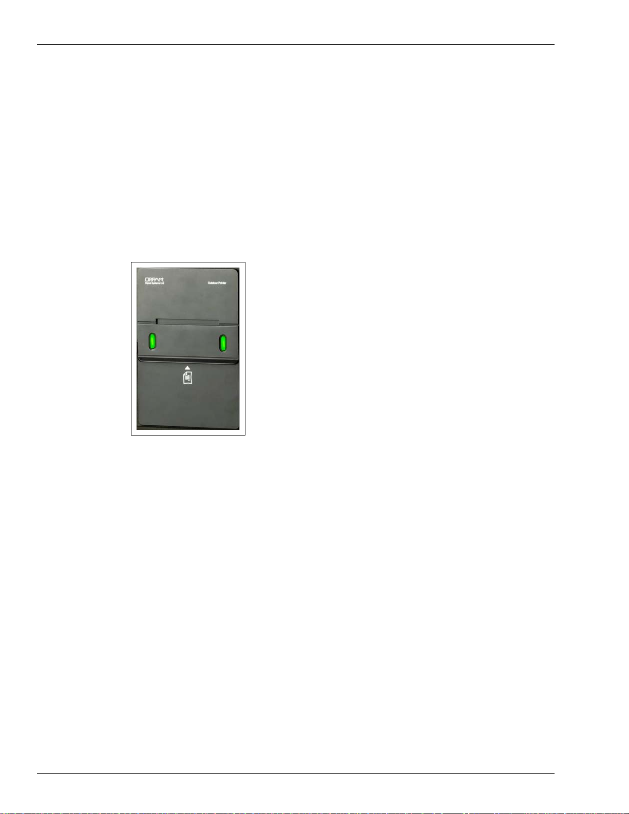
Outdoor Printer (Optional)
TopKAT PLUS includes an optional printer for receipts printout, as well as data output. The
printer is linked to the central payment terminal that sends to it the transaction data for
printout.
n
Printer module G2 is a compact, ruggedized thermal pri
of the gas station. It includes two sensors for paper usage alerts:
• Low paper sensor - activated when there is approximately 25% of
• End paper sensor - activated when printer paper runs out completely
The paper usage and receipt indications include a buzzer sound, Light E
indicators or the combination of both, dependent on its configuration.
Figure 1-5: Outdoor Printer (Optional)
ter suitable for the harsh environment
the paper roll left
m
itting Diode (LED)
8-port CommVerter
The 8-port CommVerter consists of a communication board for all TopKAT PLUS electronic
units and for the peripheral equipment interface.
The CommVerter includes an Ethernet switch, RS-485 port for electronic pumps or an
Mechanical Pump Interface
information, refer to “Printer” on page 4-1. The CommVerter communicates with the site
controller (OrCU) through a LAN (Ethernet) link.
Card (MPI-C) for interface to a mechanical pump. For more
Page 1-6 MDE-5013C TopKAT™ PLUS Installation Manual · February 2015
Page 13
TopKAT PLUS Structure Introduction
Figure 1-6: 8-port CommVerter
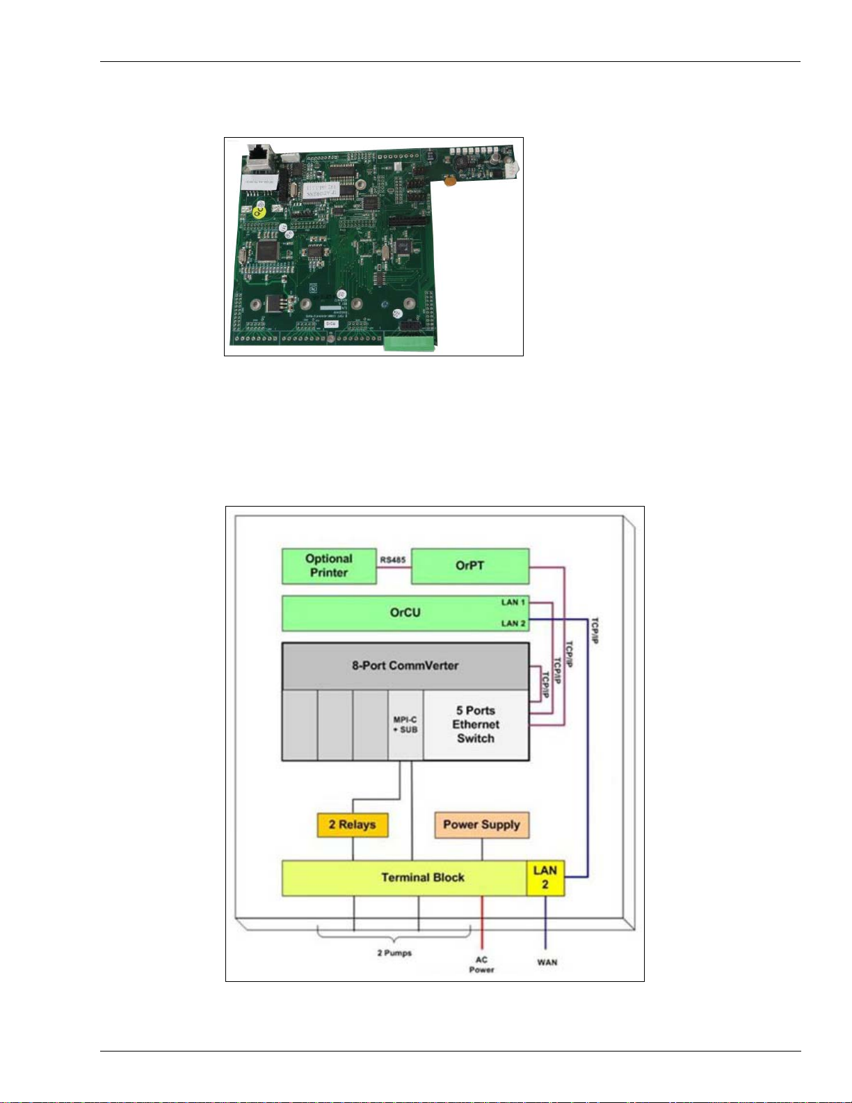
TopKAT PLUS Internal Configuration - Mechanical Pump
Figure 1-7 shows a general configuration diagram of the TopKAT PLUS up to two mechanical
pumps.
Figure 1-7: Internal Configuration Diagram - Two Mechanical Pumps
MDE-5013C TopKAT™ PLUS Installation Manual · February 2015 Page 1-7
Page 14
Introduction TopKAT PLUS Structure
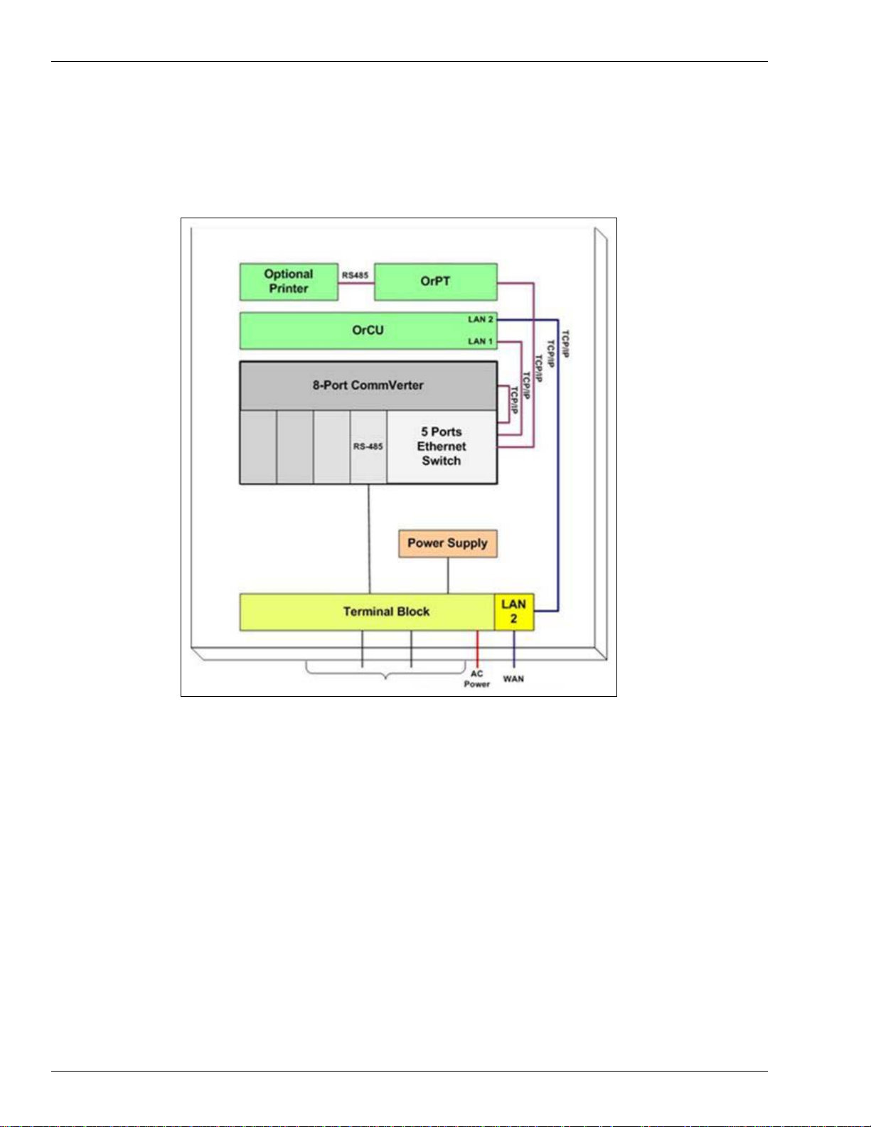
TopKAT PLUS Internal Configuration - Electronic Pump
Figure 1-8 shows a general configuration diagram of the TopKAT PLUS up to two electronic
pumps.
Figure 1-8: Internal Configuration Diagram - Two Electronic Pumps
Page 1-8 MDE-5013C TopKAT™ PLUS Installation Manual · February 2015
Page 15
TopKAT PLUS Structure Introduction
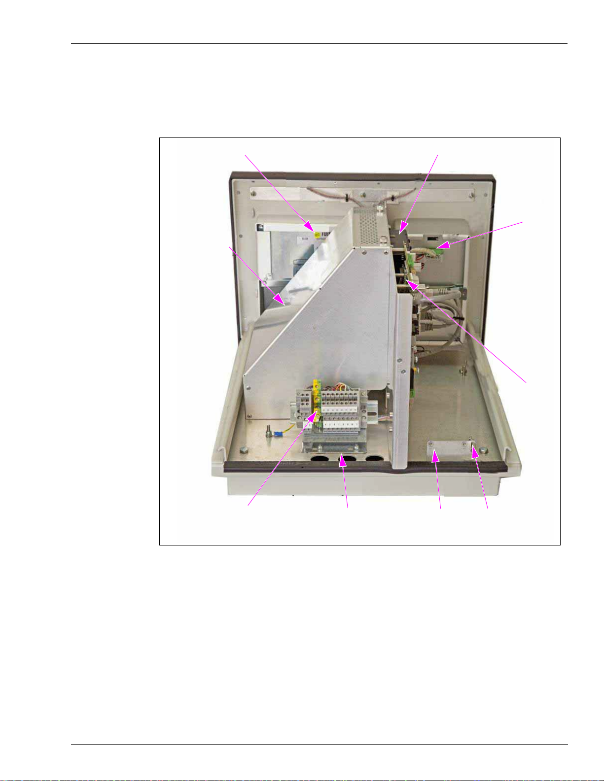
OrPT
OrCU
Printer
8-port
CommVerter
AC
Protective Cover
Terminal Block
Connection
Openings
Cover Opening
Detection
Mechanism
Ground Stud
TopKAT PLUS Main Components Location
Figure 1-9 shows the location of the main components of the TopKAT PLUS.
Figure 1-9: Internal Components Location
MDE-5013C TopKAT™ PLUS Installation Manual · February 2015 Page 1-9
Page 16
Introduction TopKAT PLUS Structure
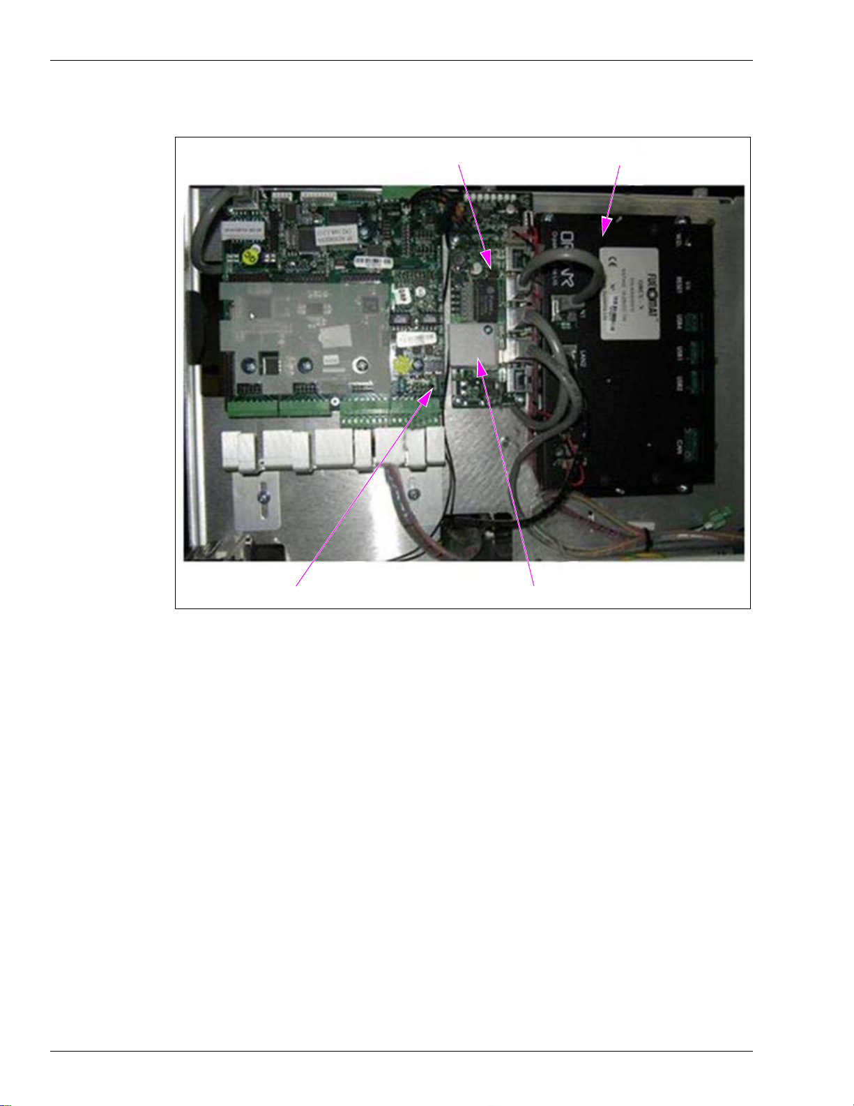
5-port Switch
OrCU
8-port CommVerter Heat Sink Cover
Figure 1-10: Internal Components Location - Right Side
Page 1-10 MDE-5013C TopKAT™ PLUS Installation Manual · February 2015
Page 17
Electrical Setup Introduction
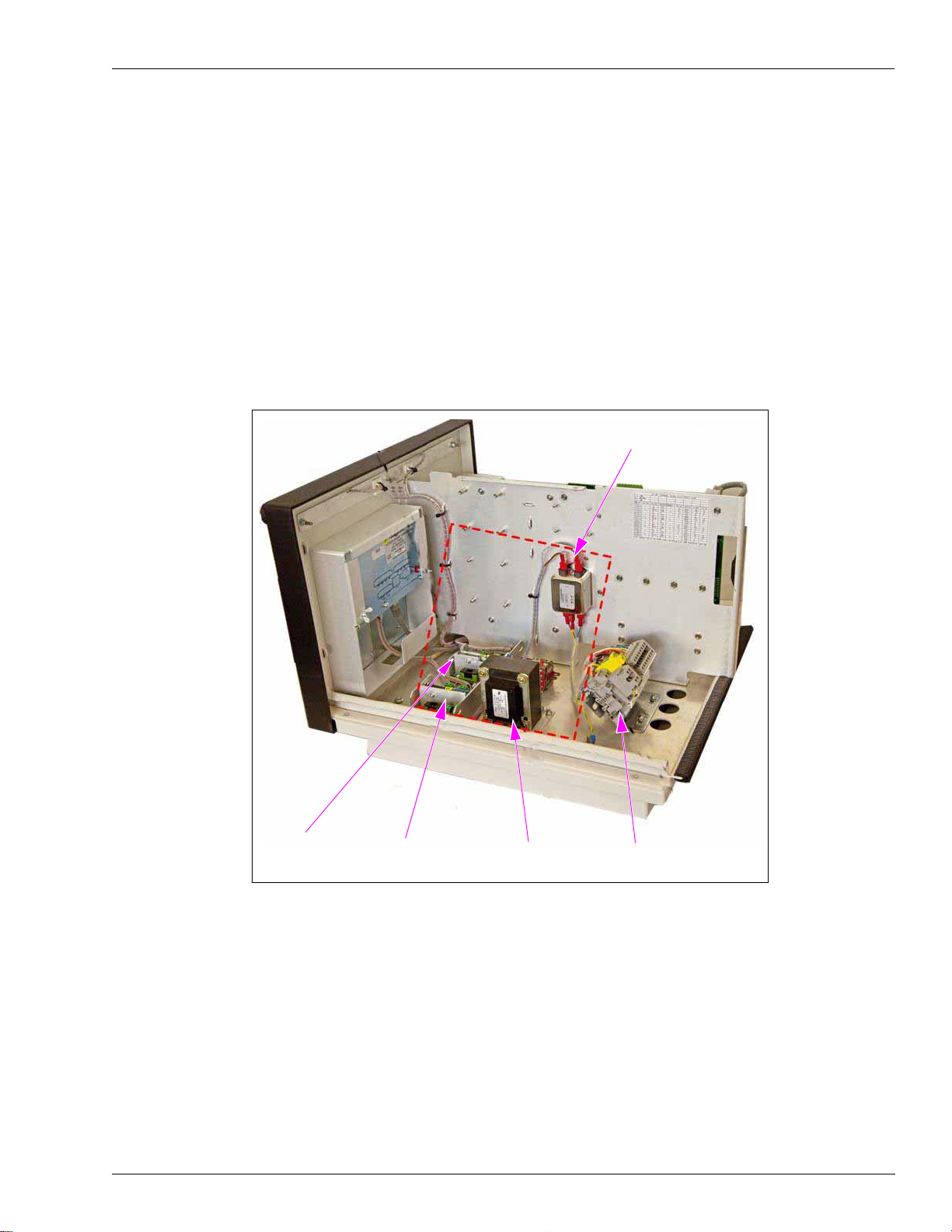
32 V Regulator
(M09680B052)
Line Filter (M09680B008)
24 V Regulator
(M09680B083)
Transformer
(M09680B022)
Terminal Block (M09680B025)
Electrical Setup
TopKAT PLUS electrical components are protected by a dedicated cover to ensure physical
separation between high voltage and low voltage in the box. The mains cable is first connected
to the terminal block. Between the terminal block and transformer, the system uses a line filter
to attenuate conducted radio frequencies - Radio Frequency Interference (RFI),
Electromagnetic Interference (EMI) - between the line and equipment. AC power is then
supplied to an AC/AC high to low transformer - 110/220 to 25 VAC.
Figure 1-11 shows the AC setup in electronic pumps configuration without the prot
cover.
Figure 1-11: AC Setup (Electronic Configuration)
ective
MDE-5013C TopKAT™ PLUS Installation Manual · February 2015 Page 1-11
Page 18

Introduction Available Configurations
Available Configurations
General
TopKAT PLUS is available in several configurations, in accordance with its intended use and
with the components installed. All configurations are manufactured in accordance with
specific customer request and receive a part number (refer to “Configurations”). Following
paragraphs describe the several configurations and t
Optional Printer
The printer in the TopKAT PLUS is provided as an option. The printer issues a printout of the
transaction to the driver.
Dispensers
TopKAT PLUS can support either mechanical or electronic dispensers, in accordance with its
configuration.
heir device composition:
Mechanical dispensers require the installation of
an MPIC card on the 8-port CommVerter.
Electronic dispensers require installation of an interface card (RS-485) on the 8-port
CommVerter.
Configurations
Following table defines all the available product numbers for the different TopKAT PLUS
configurations:
PRN
Part Number Name Dispenser
PA040500000 TopKAT PLUS (E) + - PA040501000 TopKAT PLUS (2M) - + PA040500010 TopKAT PLUS (E, PRN)* + - +
PA040501010 TopKAT PLUS (2M, PRN)* - + +
*TopKAT PLUS with printer is for inst
allation over class 1, division 2.
Note: TopKAT PLUS does not support Tank Level Gauges (TLG) or additional electronic
dispensers. Those devices require an external box or another solution.
Electronic
Mechanic 2
Printer
In the order form, customers are required
to define the part number for the specific pump card
in use (MPI-C or RS-485, refer to the following table).
No. Pump Card Description Gilbarco® Part Number
1 RS-485 Interface (8P) P.B. M09680B014
2 MPI-C + Sub Interface (8P) P.B. M09680B105
Page 1-12 MDE-5013C TopKAT™ PLUS Installation Manual · February 2015
Page 19

Security and Protection Introduction
Security and Protection
General
The transaction activities of the T opKAT PLUS are secured and protected for transmission and
authorization activities.
Authorization Security
The contactless tags include Triple-Data Encryption Standard (TDES) encrypted data for user
identification and billing. Consequently, TopKAT PLUS includes a special Security
Application Module (SAM) for decryption and matching identification. On tag reading,
TopKAT PLUS attempts to decrypt the string from the tag. TopKAT PLUS disregards tags
whose security scheme does not match the TopKAT PLUS internal SAM.
Network Security
The Ethernet LAN is isolated from the external Wide Area Network (WAN) by the site
controller (OrCU). In case of remote maintenance, a firewall must be applied either at the
router level or preferably at the home base station level.
Maintenance Security
T opKAT PLUS maintenance and setup procedures require inserting a user name and password
for access. For more information, refer to MDE-4817 SiteOmat In-House Station Controller
Setup and Maintenance Manual.
Housing
TopKAT PLUS system enclosure is made of a metal cabinet for factory installation on top of
the pump. It includes a front plastic panel and a supportive base.
The enclosure is weather-proof to sustain the harsh env
TopKAT PLUS payment panel is made of rugged plastic. The devices in its front panel are
sealed to prevent humidity and dust penetration.
TopKAT PLUS box is locked by key for safety and security. The key must be kept in a
well-kept, secure, and safe place.
The cabinet also includes an electronic mechanism for preventing unauthorized personnel
from opening the TopKAT PLUS box cover. The detection mechanism is set in the SiteOmat
application, refer to MDE-4817 SiteOmat In-house Station Contro ller Setu p and Maintenance
Manual.
ironment of a home base station.
Note: The top cover and frame are secured by a ground wire. Caution must be taken while
emoving the cover.
r
MDE-5013C TopKAT™ PLUS Installation Manual · February 2015 Page 1-13
Page 20

Introduction Specifications
Specifications
The physical, electrical, and environmental specifications applicable to the TopKAT PLUS are
displayed in the following table.
Description Specification
Supply Voltage 120-240 VAC
Power Consumption 1 A max
Operating Temperature -40 °F to +104 °F (-40 °C to +40 °C)
Storage Temperature -40 °F to +158 °F (-40 °C to +70 °C)
Humidity 80% Non-condensing
Dimensions W X H X D: 16.26 X 11.24 X 17.224” (413 X 285.5 X 437.5 mm)
Communication Interface RS-485 - 9600 bps, Half-duplex
RS-232
Ethernet RJ-45 - 10 mbps
Pump Control Maximum Current [2 Solid State
Relay Channels, (see
Power Supply Output Voltage to Pulser Unit 12 VDC +/- 20%
Power Supply Maximum Output Current 30 mA max
Pulsar Input High Level Voltage 9 to 15 VDC
Pulsar Input High Level Sink Current (at 15 V) 3 mA
In Use “On” Level (Input) 100-240 VAC, 50/60 Hz, 2 W (20 mA)
In Use “Off” Level (Input) 0 to 20 VAC
®
Recognition Suitable for Use Over Class 1, Division 2, Group D
UL
Note: When controlling 230 VAC pumps the solid state relay only con
note)]
Motor Maximum: 3/4 HP at 115 VAC or 1-1/2 HP at 230 VAC
trols one leg of the 230 VAC.
Standards
Communication Standards
TopKAT PLUS communicates, in its different models, over the following standards:
• RS-232 link
• RS-485 link
• TCP/IP over Ethernet
Security Standards
TDES encryption for payment devices (contactless tags, magnetic stripe cards, and so on).
Page 1-14 MDE-5013C TopKAT™ PLUS Installation Manual · February 2015
Page 21

Using This Manual Introduction
An operating procedure, practice, and so on, that if not correctly followed, could
result in an injury or loss of life.
WARNING
An operating procedure, practice, and so on, that if not strictly observed, could
result in damage or destruction of equipment.
CAUTION
More detailed technical/functional information in regard to relevant issue.
IMPORTANT INFORMATION
Using This Manual
This manual includes alerting comments, to draw the reader’s attention to important issues.
The comments are accompanied by symbols for ease of reference. Following comment types
are used:
Related Documents
Document
Number Description GOLD
MDE-4331 Atlas Fuel Systems Installation Manual • Gasboy Atlas
MDE-4333 Atlas Fuel Systems Site Preparation Manual • Gasboy Atlas
MDE-4334 Commercial and Retail Series Atlas Start-up/Service Manual • Gasboy Atlas
MDE-4817 SiteOmat In-House Station Controller Setup and Maintenance Manual Gasboy Fleet PLUS
MDE-4818 SiteOmat In-House Station Controller User’s Manual Gasboy Fleet PLUS
MDE-4819 OrPT Gasboy’s Payment Terminal Inst
Manual for Home-base Stations
MDE-4820 8-port CommVerter Operation and Installation Manual Gasboy Fleet PLUS
PT-1963 Illustrated Spare Parts Manual Gasboy Fleet PLUS System
allation, Setup and Oper
ation
SM
Library
• Pumps/Dispensers
• Pumps/Dispensers
• Pumps/Dispensers
t
ems
Sys
ems
Syst
Gasboy Fleet PLUS
Systems
t
ems
Sys
MDE-5013C TopKAT™ PLUS Installation Manual · February 2015 Page 1-15
Page 22

Introduction Abbreviations and Acronyms
Abbreviations and Acronyms
Term Description
ANSI American National Standards Institute
ASC Authorized Service Contractor
AWG American Wire Gauge
CAT Category
D-Box Distribution Box
DES Data Encryption Standard
EIA Electronic Industries Alliance
EMI Electromagnetic Interference
FHO Fleet Head Office
GOLD Gilbarco Online Documentation
J-box Junction Box
LAN Local Area Network
LCD Liquid Crystal Display
LED Light Emitting Diode
MPI Mechanical Pump Interface
MPI-C Mechanical Pump Interface Card
®
NEC
NFPA National Fire Protection Association
OrCU Orpak Controller Unit
OrPT Orpak/Outdoor Payment Terminal
PS Pump Server
RFI Radio Frequency Interference
RFID Radio Frequency Identification
RTC Real Time Clock
SAM Security Application Module
SSE Site Service Equipment
SSL Secured Socket Layer
STP Submersible Turbine Pump
TCP/IP Transmission Control Protocol/Internet Protocol
TDES Triple-Data Encryption Standard
TIA Telecommunications Industry Association
TLG Tank Level Gauges
UL Underwriters Laboratories
VIT Vehicle Information Transceiver
WAN Wide Area Network
National Electrical Code
Page 1-16 MDE-5013C TopKAT™ PLUS Installation Manual · February 2015
Page 23
2 – Important Safety Information
Notes: 1) Save this Important Safety Information section
in a readily accessible location.
2) Although DEF is non-flammable, diesel is
flammable. Therefore, for DEF cabine ts that are
attached to diesel dispensers, follow all the
notes in this section that pertain to flammable
fuels.
This section introduces the hazards and safety precautions
associated with installing, inspecting, maintaining or servicing
this product. Before performing any task on this product, read
this safety information and the applicable sections in this
manual, where additional hazards and safety precautions for
your task will be found. Fire, explosion, electrical shock or
pressure release could occur and cause death o r serious injury,
if these safe service procedures are not followed.
Preliminary Precautions
You are working in a potentially dangerous environment of
flammable fuels, vapors, and high voltage or pressures. Only
trained or authorized individuals knowledgeable in the related
procedures should install, inspect, maintain or service this
equipment.
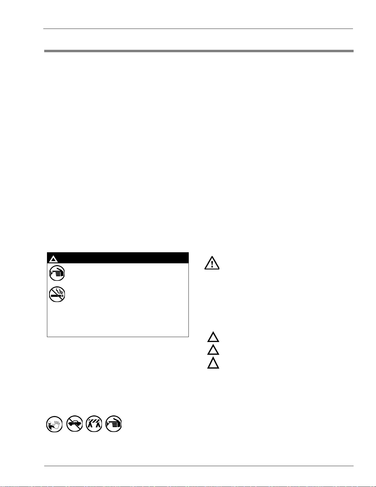
Emergency Total Electrical Shut-Off
The first and most important in formation you must know is how
to stop all fuel flow to the pump/dispenser and island. Locate
the switch or circuit breakers that shut off all power to all fueling
equipment, dispensing devices, and Submerged Turbine
Pumps (STPs).
The EMERGENCY STOP, ALL STOP, and
PUMP STOP buttons at the cashier ’s station
WILL NOT shut off electrical power to the
pump/dispenser. This means that even if you
activate these stops, fuel may continue to flow
uncontrolled.
You must use the TOTAL ELECTRICAL
SHUT-OFF in th e cas e of an emerge nc y a nd not
the console’s ALL STOP and PUMP STOP or
similar keys.
!
WARNING
!
Total Electrical Shut-Off Before Access
Any procedure that requires access to electrical component s or
the electronics of the dispenser requires total elect rical shut off
of that unit. Understand the function and location of this switch
or circuit breaker before inspecting, installing, maintaining, or
servicing Gasboy equipment.
Evacuating, Barricading and Shutting Off
Any procedure that requires access to the pump/dispenser or
STPs requires the following actions:
• An evacuation of all unauthorized persons and vehicles from
the work area
• Use of safety tape, cones or barric ades at the affected unit(s)
• A total electrical shut-off of the affected unit(s)
Read the Manual
Read, understand and follow this manual and any other labels
or related materials supplied with this equipment. If you do not
understand a procedure, call a Gasboy Authorized Serv ice
Contractor or call the Gasboy Support Center at
1-800-444-5529. It is imperative to your safety and the safe ty of
oth
e
rs to understand the procedures before beginning work .
Follow the Regulations
Applicable information is available in National Fire Protection
Association (NFPA) 30A; Code for Motor Fuel Dispensing
Facilities and Repair Garages, NFPA 70; National Electrical
Code (NEC), Occupatio nal Safety and Health Administrati on
(OSHA) regulations and federal, state, and local codes. All
these regulations must be followed. Failure to install, inspect,
maintain or service this equipment in accordance with these
codes, regulations and standards may lea d to leg al citation s
with penalties or affect the safe use and operation of the
equipment.
Replacement Parts
Use only genuine Gasboy replacement p art s and re trofit kits on
your pump/dispenser. Using parts other than genuine Gasboy
replacement parts could create a safety hazard and violate
local regulations.
Safety Symbols and Warning Words
This section provides important information about wa rn ing
symbols and boxes.
Alert Symbol
This safety alert symbol is used in this manual and on
warning labels to alert you to a precaution which must be
followed to prev
ent potential personal safety hazards. Obey
safety directives that follow this symbol to avoid possible injury
or death.
Signal Words
These signal words used in this manual and on warning labels
tell you the seriousness of particular safety hazards. The
precautions below must be followe d to prevent death, injury or
damage to the equipment:
DANGER: Al
erts yo
u to a hazard or unsafe practice
which will result in death or serious injury.
WARNING: Alerts
you to a hazard or unsafe practice
that could result in death or serious injury.
CAUTION with Alert symbol: Designates a hazard or
un
safe practice which may result in minor injury.
CAUTION w
i
thout Alert symbol: Designates a hazard or
unsafe practice which may result in property or
equipment damage.
Working With Fuels and Electrical Energy
Prevent Explosions and Fires
Fuels and their vapors will explode or burn, if ignited. Spilled or
leaking fuels cause vapors. Even filling customer tanks will
cause potentially dangerous vapors in the vicinity of the
dispenser or island.
DEF is non-flammable. Therefore, expl
osion and fire safety
warnings do not apply to DEF fluid lines.
!
!
!
Important Safety Information
MDE-5013C TopKAT™ PLUS Installation Manual · February 2015 Page 2-1
Page 24

Important Safety Information
The pump/dispenser contains a chemical known to the
State of California to cause cancer.
WARNING
!
The pump/dispenser contains a chemical known to the
State of California to ca use birth defects or other
reproductive harm.
WARNING
!
Gasoline/DEF ingested may cause
unconsciousness and burns to internal organs.
Do not induce vomiting. Keep airway open.
Oxygen may be needed at scene. Seek medical
advice immediately.
DEF generates ammonia gas at high er temperatures.
When opening enclosed panels, allow the unit to air out to
avoid breathing vapors.
If respiratory difficulties develop, move victim away from
source of exposure and into fresh air. If symptoms persist,
seek medical attention.
WARNING
!
WARNING
!
Gasoline inhaled may cause unconsciousness
and burns to lips, mouth and lungs.
Keep airway open.
Seek medical advice immediately.
WARNING
!
Gasoline/DEF spilled in eyes may cause burns to
eye tissue.
Irrigate eyes with water for approximately
15 minutes.
Seek medical advice immediately.
WARNING
!
Gasoline/DEF spilled on skin may cause burn s.
Wash area thoroughly with clear water.
Seek medical advice immediately.
WARNING
!
DEF is mildly corrosive. Avoid cont act with eyes , skin, and
clothing. Ensure that eyewash stations and safety
showers are close to the work location. Seek medical
advice/recommended treatment if DEF spills into eyes.
WARNING
!
No Open Fire
Open flames from matches, lighters, welding torches or
other sources can ignite fuels and their vapors.
No Sparks - No Smoking
Sparks from starting vehicles, starting or using power tools,
burning cigarettes, cigars or pipes can also ig nite fuels and their
vapors. Static electricity, including an electrostatic charge on
your body, can cause a spark sufficient to ignite fuel vapors.
Every time you get out of a vehicle, touch the metal of your
vehicle, to discharge any electrostatic charge before you
approach the dispenser island.
Working Alone
It is highly recommended that someone who is capab l e of
rendering first aid be present during servicing. Familiarize
yourself with Cardiopulmonary Resuscitation (CPR) methods, if
you work with or around high voltages. This informa tion is
available from the American Red Cross. Always advise the
station personnel about where you will be working, and caution
them not to activate power while you are working on the
equipment. Use the OSHA Lockout/Tagout procedures. If you
are not familiar with this requirement, refer to this information in
the service manual and OSHA documentation.
In an Emergency
Inform Emergency Personnel
Compile the following information and inform emergency
personnel:
• Location of accident (for example, address, front/back of
building, and so on)
• Nature of accident (for example, possible heart attack, run
over by car, burns, and so on)
• Age of victim (for example, baby, teenager, middle-age,
elderly)
• Whether or not victim has received first aid (for example,
stopped bleeding by pressure, and so on)
• Whether or not a victim has vomited (for example, if
swallowed or inhaled something, and so on)
Working With Electricity Safely
Ensure that you use safe and established practices in working
with electrical devices. Poorly wired devices may cause a fire,
explosion or electrical shock. Ensure that grounding
connections are properly made . Take care that sealing devices
and compounds are in place. Ensure that you do not pinch wires
when replacing covers. Follow OSHA Lockout/Tagout
requirements. Station employees and service contrac tors need
to understand and comply with this program complete ly to
ensure safety while the equipment is down.
Hazardous Materials
Some materials present inside electronic enclosures may
present a health hazard if not handled correctly . Ensure that you
clean hands after handling equipment. Do not place any
equipment in the mouth.
Page 2-2 MDE-5013C TopKAT™ PLUS Installation Manual · February 2015
IMPORTANT: Oxygen may be needed at scene if gasoline has
been ingested or inhaled. Seek medical advice immediately.
Lockout/Tagout
Lockout/Tagout covers servicing and maintenance of machines
and equipment in which the unexpecte d energization or sta rt-up
of the machine(s) or equipment or release of stored energy
could cause injury to employees or personnel. Lockout/Tagout
applies to all mechanical, hydraulic, chemical, or other energy,
but does not cover electrical hazards. Subpart S of 29 CFR Part
1910 - Electrical Hazards, 29 CFR Part 1910.333 contains
specific Lockout/Tagout provision for electrical hazards.
Page 25
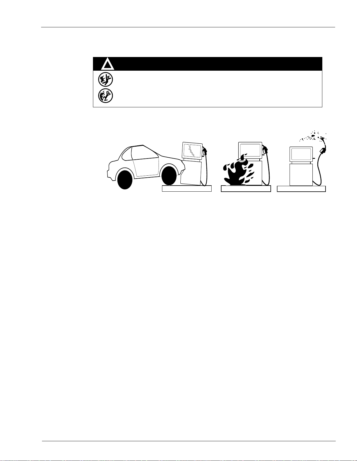
Hazards and Actions
WARNING
Spilled fuels, accidents involving pumps/dispensers, or uncontrolled fuel flow create a
serious hazard.
Fire or explosion may result, causing serious injury or death.
Follow established emergency procedures.
DEF is non-flammable. However it can create a slip hazard. Clean up spills promptly.
!
Collision of a Vehicle with Unit Fire at Island Fuel Spill
The following actions are recommended regarding these hazards:
Important Safety Information
• Do not go near a fuel spill or allow anyone else in the area.
• Use station EMERGENCY CUTOFF immediately . Turn off all system circuit breakers to the island(s).
• Do not use console E-STOP, ALL STOP, and PUMP STOP to shut off power. These keys do not
remove AC power and do not always stop product flow.
• Take precautions to avoid igniting fuel. Do not allow starting of vehicles in the area. Do not allow
open flames, smoking or power tools in the area.
• Do not expose yourself to hazardous conditions such as fire, spilled fuel or exposed wiring.
• Call emergency numbers.
MDE-5013C TopKAT™ PLUS Installation Manual · February 2015 Page 2-3
Page 26

Important Safety Information
This page is intentionally left blank.
Page 2-4 MDE-5013C TopKAT™ PLUS Installation Manual · February 2015
Page 27

General TopKAT PLUS Installation Procedures
Before installing or servicing equipment, carefully observe the warnings and precautions
provided in “Important Safety Information” on page 2-1.
WARNING
3 – TopKAT PLUS Installation Procedures
General
TopKAT PLUS units can be supplied factory mounted on an Atlas pump/dispenser or with a
pedestal for interface to mechanical or electronic register pumps/dispensers. This section
provides installation procedures for both types.
These procedures include:
• TopKAT PLUS box installation
• Wiring
• Post installation check
Installation Specifications
General
Installation procedures and requirements depend, to some extent, on the specific fuel dispenser
models. Therefore, use the information in this section to develop factory installation plans for
each specific dispenser or suction pump.
Precautions and Safety Notes
Before actual installation activities, carefully observe the following precautions and safety
notes:
• Ensure that actual installation is performed by experienced personnel as required by the
National Fire Protection Association-30 (NFP A-30) “Flammable and Combustible Liquids
Code”, NFPA-30A “Code for Motor Fuel Dispensing Facilities and Repair Garages”,
®
NFPA-70A
applicable safety codes and regulations.
• System power may come from more than one source
including pumps, before attempting to work on the system.
• Do not connect power to the TopKAT PLUS or pump, until the complete installation is
inspected and
, National Electric Code (NEC), federal, state, and local codes, and any other
certified.
. Disconnect all power sources,
MDE-5013C TopKAT™ PLUS Installation Manual · February 2015 Page 3-1
Page 28

TopKAT PLUS Installation Procedures Installation Specifications
Allow a minimum of 20-inches clearance at rear of the TopKat PLUS head assembly for
pedestal and Atlas mounted units.
IMPORTANT INFORMATION
Types of Cables
Following table lists the types of cable in use for the wiring of the TopKAT PLUS system:
No. Function Type
2
1 AC Power Power Cable, 3 X 1.5 mm
Control to Pumps (Valves or Engine)
In Use Signal
2 Pulser Data Communication Cable, 300 V RMS, 194 ºF (90 ºC), Shielded
3 LAN Category-5E (CAT-5E), Four Conductor Insulator Cable (042GA00007
4 GND Ground Cable 0.4” (10.8 mm
Note: Use the appropriate gauge wire size for the AC power for pump
standards.
w
isted-pair, Oil-resistant, 24 AWG, Low Capacitance below
T
60 PF/meter similar to Belden
or 042GALF007
300 V RMS, 194 ºF (90 ºC) similar to Belden 121700A
- Gilbarco part number M12673B001) or Shielded,
NYY (14 AWG), in accordance with local
®
9729 Cable
2
)
s, dispensers, and fueling equipment.
Types of TopKAT PLUS Units
There are three types of TopKAT PLUS configurations as follows:
• Electronic TopKAT PLUS mounted on an Atlas 9800 unit
• Electronic TopKAT PLUS mounted on a pedestal
• Mechanical TopKAT PLUS mounted on a pe destal
Head Assembly Dimensions
The T opKat PLUS head assembly that is mounted on a pedestal or Atlas 9800 electronic pump
is 116.5 X 11.4 X 18” (W X H X D).
Page 3-2 MDE-5013C TopKAT™ PLUS Installation Manual · February 2015
Page 29

Installation Specifications TopKAT PLUS Installation Procedures
23
Barrier Plate
11-3/4
48
11-1/2
1-1/4
1-1/4
9-1/4
5-3/4
11-1/2
2-1/2
2-1/2
5-7/8
11-3/4
Bottom View
A
A
AA
B
BB
A = 1/2” Mounting Holes (Bottom Plate)
B = Dual Knockouts For 3/4” or 1” Conduit
(Barrier Plate)
11.4
16.5
Front View
Note: All dimensions are in inches.
9-1/4
Pedestal Dimensions
To ensure a reliable and proper installation it is very important to know the pedestal
dimensions. The mechanical and electronic TopKAT PLUS assembly mounted on the
pedestals are shown in Figure 3-1.
Figure 3-1: Pedestal Dimensions
MDE-5013C TopKAT™ PLUS Installation Manual · February 2015 Page 3-3
Page 30

TopKAT PLUS Installation Procedures Conduits
Mechanical Pump/DispenserMechanical Pump/Dispenser
TopKAT PLUS
Optional
Possible Conduits
in Pedestal
Office
WAN
MCC
UPS
TCP/IP
CAT-5E
Junction
Box
Low Voltage Conduit
TCP/IP
GND
Low Voltage Conduit
High Voltage Conduit
Isle
Junction
Box
High Voltage Conduit
AC
Pulser
In Use
Control
Conduits
General
The installation of the TopKAT PLUS at the island requires digging and setting several
conduits in the station ground. The conduits are required for the routing and protection of the
different types of cables in use in a home base station with TopKAT PLUS. In sites where the
infrastructure is already set up, you can use the existing conduits only if they meet the
requirements defined in “Conduit Requirements”.
Conduit Requirements
Conduits must comply with:
• All conduits must be made and installed according to loca
• High-voltage AC and low-voltage DC must NOT be combined
Junction Box (J-box) or wire through.
• The maximum distance for the LAN communication is 333 feet. Cables must
in a separate low voltage conduit, away from AC wires. Communication range can be
extended with third-party devices.
• All conduits must be inserted in the TopKAT PL
US pedestal through the holes and
knockouts provided in the lower barrier plate.
• After completing the installation, there must not be any unused conduit openings in the
ba
rrier plate. The clearance between conduits and openings in the barrier plate must not be
more than 1/64-inch.
l regulations.
in a common conduit,
be inserted
Figure 3-2: Conduit Layout for Mechanical Pump
Page 3-4 MDE-5013C TopKAT™ PLUS Installation Manual · February 2015
Page 31

Barrier Plate Conduit Penetration TopKAT PLUS Installation Procedures
Electronic Pump/DispenserElectronic Pump/Dispenser
TopKAT PLUS
Possible Conduits
in Pedestal
Office
WAN
MCC
UPS
Optional
TCP/IP
CAT-5E
J-box
J-box
Low Voltage Conduit
TCP/IP
GND
AC
Low Voltage Conduit
High Voltage Conduit
Isle
Figure 3-3: Conduit Layout for Electronic Pump
Barrier Plate Conduit Penetration
The pedestal barrier plate makes the pedestal mounted TopKAT PLUS suitable for installation
over a class 1, division 2 hazardous location. Field installed conduit must run completely up
through the barrier plate. The conduit must be threaded where it passes through the barrier
plate. There must be no unused conduit openings in the barrier plate when installation is
completed. Clearance between conduits and openings in the barrier plate through which
conduit passes must not be more than 1/64-inch.
MDE-5013C TopKAT™ PLUS Installation Manual · February 2015 Page 3-5
Page 32

TopKAT PLUS Installation Procedures Barrier Plate Conduit Penetration
Approved Location for TopKAT PLUS
TopKAT PLUS
Class 1, Division 2 Safety Area
Dispenser
Dispenser
Ground Level
Isle
20”
18”
18”18”18”
Sealing Conduits
The conduits must be sealed in accordance with NFPA requirements and local regulations, to
prevent the passage of gases through conduits, cables, and conductors. The fittings are
requested wherever volatile liquids or gases are present in the surroundings (see Figure 3-4).
Figure 3-4: Conduit Fitting
Safety Distance
Figure 3-5 shows the safety distances required for the installation of the TopKAT PLUS
adjacent to the dispensers. When mounting the
18 inches (0.5 m) between the unit and any of the pumps or the dispensers must be maintained.
This clearance allows room
T opKAT PLUS is designed and approved for installation and use at a convenient location at or
ne
Figure 3-5: TopKAT PLUS - Installation Control Drawing
TopKAT PLUS, a minimum clearance of
for the wiring and maintenance of the system.
ar fuel island in the appropriate hazardous (classified) location:
• Where hazardous location is classified as class 1, division 2 an
d it does not extend higher
than 18 inches (0.5 m) from surface and
• A minimum safety separation of 18 inches (0.5 m) from any nearest
pump/dispenser.
Page 3-6 MDE-5013C TopKAT™ PLUS Installation Manual · February 2015
Page 33

TopKAT PLUS Pedestal Mounting Instructions TopKAT PLUS Installation Procedures
TopKAT PLUS Pedestal Mounting Instructions
The TopKAT PLUS head assembly and pedestal assembly are packaged in their own boxes
and shipped in a large box. After removing them from the large box, the two units must be
connected together using the following procedure.
Parts List
Following parts are required for the TopKAT PLUS pedestal mounting:
• Pedestal and Head Assembly
TopKAT PLUS
Ped
Description
i
TopKAT PLUS Pedestal - Electronic D
TopKAT PLUS Pedestal - Mechanical Dispenser OrTOP (2M) PA040501000 PA040501100 800938972
TopKAT PLUS Pedestal - Electronic D
with Printer
T opKA T PLUS Pedest al - Mechanical Dispenser
with Printer
TopKAT Pedestal M12706002 - -
spenser OrTOP (E) PA040500000 PA040500100 800938970
i
spenser
OrTOP (E, PRN) PA040500010 PA040500110 800938971
OrTOP (2M, PRN) PA040501010 PA040501110 800938973
estal
Assembly
TopKAT PLUS
Head Part
Number
Orpak
OrTOP
Part Number
• Hardware Kit
•Gasket
• Installation Instructions
To install the TopKAT PLUS pedestal, proceed as follows:
1 Install and secure the pedestal to the island using the four holes at the bottom of the pedestal
with anchor bolts before installing the head assembly. This will prevent the completed
assembly from possibly falling over.
Note: To access the four inside bottom mounting holes, re
2 Position the pedestal so that the front side faces the fueling lane. Secure the pedestal to the
move the rear lower door panel.
island using the four mounting holes inside the base of the unit.
3 Install the black rubber gasket on top of the pedestal ensuring that the holes for the wiring are
aligned properly and not blocked.
4 Mount the TopKAT head assembly onto the top of the pedestal using the four threaded studs as
a guide. Secure the head assembly using a flat washer, lockwasher, and 1/4 -20-inch nut onto
each of the four post and tighten.
a Remove the TopKAT cover by unlocking the rear key lock and slide the cover to the rear
side of the unit.
MDE-5013C TopKAT™ PLUS Installation Manual · February 2015 Page 3-7
Page 34

TopKAT PLUS Installation Procedures TopKAT PLUS Pedestal Mounting Instructions
Rear View
Side View
Top Mounting Studs
Facing Front
b Ensure that you do not remove the cover completely until the yellow ground wire that
connects the cover to the grounding lug of the unit is removed.
Note: The front of the pedestal has the over hang, an
d the mounting studs are arranged in such
a manner that the TopKAT head assembly can only be mounted one way, facing
frontwards (see Figure 3-6).
Figure 3-6: TopKAT PLUS Pedestal
Page 3-8 MDE-5013C TopKAT™ PLUS Installation Manual · February 2015
Page 35

Connections to TopKAT PLUS - Pedestal Mounted Units TopKAT PLUS Installation Procedures
Connections to TopKAT PLUS - Pedestal Mounted Units
All connections to the post mounted TopKAT PLUS must be performed to the terminal block
located at the bottom of the TopKAT PLUS box (see Figure 3-7 and Figure 3-8 on page 3-10).
The required connections are:
• Dispenser wiring connections (mechanical
- Pulser (low voltage)
- In use signal (high
- Solenoid valve (high voltage)
• Communications (Atlas 9800 electronic dispensers):
- Pump communication line (RS-485)
• Mains AC power and ground (electronic and mechanical dispensers)
• LAN connection. LAN cable is directly connected to
Figure 3-7: TopKAT PLUS Terminal Block - Mechanical Pump
voltage)
dispensers):
LAN2 connection
on the OrCU.
MDE-5013C TopKAT™ PLUS Installation Manual · February 2015 Page 3-9
Page 36

TopKAT PLUS Installation Procedures Connections to TopKAT PLUS - Pedestal Mounted Units
For the electronic TopKAT factory-installed on top of an Atlas 9800, all the required
wiring for the 9800 electronic pumps including the RS-485 communication, the LAN
communications, and AC power is pre-wired from the factory. No other connections are
made to the terminal blocks.
IMPORTANT INFORMATION
Figure 3-8: TopKAT PLUS Terminal Block - Electronic Pump (Pedestal Mount)
Page 3-10 MDE-5013C TopKAT™ PLUS Installation Manual · February 2015
Page 37

Wiring TopKAT PLUS Installation Procedures
Wiring
Types of Wiring
The wiring in the terminal block differs in accordance with the type of pump controlled by the
TopKAT PLUS. There are several types of pumps:
• Mechanical pumps
• Electronic pumps
Following section provides the “Wiring Requirements” for ea
Wiring Requirements
Before inserting any wire to the terminal block, proceed as follows:
1 Insert the wire with a terminal lug only (see Figure 3-9).
2 Attach the lug to the wire using the proper terminal crimper.
3 For UL-listing, the terminal lug must be a UL recognized component.
Figure 3-9: Terminal Lug
ch type of pump:
Note: Mark each cable at its both ends with a number or sign that will identify its functionality
in the future.
Types of Cables
Following cables are required for the TopKAT PLUS installation:
• Power cable: In accordance with local regulations
• LAN cable: CAT-5E [refer to “Field Wiring Requirements (LAN/WAN)” on page 3-12]
• RS-485/pulser: Communication cable, twisted-pair, separately
For example, Belden 8723 or equivalent.
Note: The shield must be connected to ground on one side of the cable only, preferab ly on the
pKAT PLUS side.
To
MDE-5013C TopKAT™ PLUS Installation Manual · February 2015 Page 3-11
shielded, low capacitance.
Page 38

TopKAT PLUS Installation Procedures Wiring
Field Wiring Requirements (LAN/WAN)
Wiring must be installed in accordance with ANSI/TIA/EIA 568 B standards and
amendments.
Recommendations for CAT-5E Cable
Following are Gasboy recommendations for installing the CAT-5E cable (gas-and
oil-resistant) for Site Service Equipment (SSE):
• The Ethernet cable to the pumps/dispensers
requirements, for example, gas- and oil-resistant, and vapor-resistant properties.
• CAT-5E cable is viable for typical installations un
is not run near the equipment that generates electrical noise such as large motors and
power switching equipment. An example of a noise source to avoid is a variable speed
Submersible Turbine Pump (STP).
• It is crucial that the installer follows the NEC, Article 501 requiremen
outer jacket and spreading the wire pairs at the seal-off points, so that a good vapor seal is
achieved. This is required because most CAT-5E cables will conduct vapors inside their
outer jacket (see Figure 3-10).
Note: This is not required if Four Conductor Insulator Cable (042GA00007 or
042GALF007 - Gilbarco part number M12673B001) is used. This cable will not
conduct vapors inside the outer jacket.
is designed to comply with forecourt wiring
der 280 feet of cable length, if the cable
ts by removing the
Figure 3-10: CAT-5E Cable Installation
• CAT-5E cable must not share the conduit with AC, but can share the conduit with pulsers
or other CAT-5E cables.
• If an Ethernet hub is used, it must be of commercial quality
. Commercial Ethernet
switches are a family of fixed configuration standalone devices that provide desktop.
10/100 fast Ethernet and 10/100/1000 Gigabit Ethernet connectivity for entry level
enterprise
, medium-sized, and branch office networks to enable enhanced LAN services.
• The recommended CAT-5E cable is Fou r Con ductor Insulator Cable (042GA00007 or
042GALF0
07 - Gilbarco part number M12673B001) or an equivalent. The CAT-5E
qualified cable has gas and oil-resistant inner and outer insulation, and vapor resistant
properties.
• A patch panel is recommended (optional) to connect the CAT
-5E cable to the network
RJ-45. The patch panel and LAN wiring must be LAN-certified and follow TIA/EIA LAN
568-
B wiring standards.
Page 3-12 MDE-5013C TopKAT™ PLUS Installation Manual · February 2015
Page 39

Wiring TopKAT PLUS Installation Procedures
TopKAT PLUS is shipped configured for 115 VAC po wer supply. Ensure care to set it
accordingly to your local AC power supply specifications. Failure to do so may result in
damages.
WARNING
AC Power Connection
The AC power input is connected to the terminal block. Between the terminal block and
transformer, the system uses a line filter to attenuate conducted RFI and EMI - between the
line and equipment. AC power is then supplied to an AC/AC high to low
transformer -110/220 to 25 VAC. T ransformer can be fed either to 1 10 or 2 20 VAC. The power
supply setup jumpers shown in Figure 3-11 must be set to match the AC power input to the
TopKAT PLUS. A settings label is also found beside the terminal block. For dispenser
mounted T op KAT PLUS, the power supply setup jumpers must be set to match the micro feed
input to the Atlas pump/dispenser.
• For 115 VAC input (default setting), there must be a jumper wire from position 1 of the
setup jumper to position 5 and from posi
• For 230 VAC input, there must be a jumper wire from position 5
position 2.
tion 2 to position 6.
of the setup jumper to
Figure 3-11: Power Supply Setup Jumpers
MDE-5013C TopKAT™ PLUS Installation Manual · February 2015 Page 3-13
Page 40

TopKAT PLUS Installation Procedures Mechanical Pump - Wiring
Dangerous AC voltages that can cause death or serious personal injury are used to power
the product. Always disconnect power before starting any work.
WARNING
Mechanical Pump - Wiring
General
This device is intended to be connected to UL-listed dispensers equipped with a J-box of
sufficient volume. These connections are not suitable for direct connection to intrinsically safe
devices. All wiring is to be in compliance with NFPA 70 and NFPA 30A.
The wiring for mechanical pumps
is provided in two modes:
• Following table lists the wiring in the sequential order of the terminals. This table provides
signal name and a functional description of the signal.
the
• Figure 3-12 on page 3-15 shows the wiring list for connection to the terminal,
in the wiring label attached to the inner side of the unit. The wiring l
physical location of the wires in the terminal block.
Terminal Block - Pin-out Connections for Mechanical Pumps
Following table lists the TopKAT PLUS terminal block connections for mechanical pumps:
Terminal
No. Signal Name Functional Description
1 LINE_IN_(115/230 V) Line Connection, TopKAT PLUS Power Input
2 NEUTRAL_IN_(115/230 V) Neutral Connection, TopKAT PLUS Power Input
3 GROUND_IN_(115/230 V) Ground Connection, TopKAT PLUS Power Input
4 LINE_1 Pump Control 220/110 VAC Input - Nozzle 1
5 LOAD_1 Pump Control Output - Nozzle 1
6 LINE_2 Pump Control 220/110 VAC Input - Nozzle 2
7 LOAD_2 Pump Control Output - Nozzle 2
8 IN_USE_1_ A(AC) Handle Up - In Use Signal Input - Nozzle 1
9 IN_USE_1_ B(RETURN) Handle Up - AC In Use Signal Return - Nozzle 1
10 IN_USE_2_ A(AC) Handle Up - In Use Signal Input - Nozzle 2
11 IN_USE_2_ B(RETURN) Handle Up - AC In Use Signal Return - Nozzle 2
12 -DC OUT FOR BY-PASS_2 Connection to External Bypass Nozzle 2
13 BY-PASS_2_IN Connection to External Bypass Nozzle 2
14 PULSER_1 Pulser Input - Nozzle 1
15 PULSER_2 Pulser Input - Nozzle 2
16 +12 V_2_P +12 VDC Output to Pulser - Nozzle 2
17 -DC OUT FOR BY-PASS_1 Connection to External Bypass Nozzle 1
18 BY-PASS_1_IN Connection to External Bypass Nozzle 1
19 GND_1_P Nozzle Grounding - Nozzle 1
20 GND_2_P Nozzle Grounding - Nozzle 2
21 +12 V_1_P +12 VDC Output to Pulser - Nozzle 1
as published
abel follows the
Page 3-14 MDE-5013C TopKAT™ PLUS Installation Manual · February 2015
Page 41

Mechanical Pump - Wiring TopKAT PLUS Installa tio n Pro cedures
Figure 3-12: TopKAT PLUS - Mechanical Pump Wiring List Label
Mechanical Pump - Required Connections
This paragraph describes the required wiring connections between the mechanical pump and
TopKAT PLUS. Figure 3-13 and Figure 3-14 on page 3-16 show a schematic diagram of the
connections between the TopKAT PLUS an
on page 3-17 shows a detailed wiring diagram between the TopKAT PLUS terminal block and
pump components.
Pulse Input
es
Wir
Handle Status
Input Wi
res
Authorization
Output Wi
TopKAT PLUS ratings for above signals are as follows:
The dispenser outputs pulses to the system by means of the pulser unit,
installed in accordance with the manufacturer instructions. The pulse rate
per volume (liter/gallon) is determined by the pulser unit. It is programmed
as a “factor” in the SiteOmat.
The handle signal is used to signal the system that the pump is “In Use”
mode. When the dispenser handle is lifted, this contact closes. This signals
the system that the pump is “In Use” or that the transaction ended.
The dispenser requires an authorization signal from the TopKAT PLUS to
res
start a sale transaction. Without this authorization signal, the electric valve
(or pump) does not open and the sale transaction does not begin. The
TopKAT PLUS switches the AC power signal to the valve. When the
dispenser receives the authorization signal, fuel starts to flow. This signal is
also referred to as the LOAD.
d the mechanical pump components. Figure 3-15
Signal TopKAT PLUS Rating
Pulser Input 3 mA, 15 VDC max.
Pulser Power Output 12 VDC, 30 mA max.
In Use Input 100-240 VAC, 50/60 Hz, 2 W (20 mA)
Load 3/4 HP @115 V
1.5 HP @ 240 V
MDE-5013C TopKAT™ PLUS Installation Manual · February 2015 Page 3-15
Page 42

TopKAT PLUS Installation Procedures Mechanical Pump - Wiring
Figure 3-13: Mechanical Pump - Single Dispenser Connections
Figure 3-14: Mechanical Pump - Twin Dispenser Connections
Page 3-16 MDE-5013C TopKAT™ PLUS Installation Manual · February 2015
Page 43

Mechanical Pump - Wiring TopKAT PLUS Installa tio n Pro cedures
Figure 3-15: TopKAT PLUS and Mechanical Pump - Terminal Block Detailed
Connections
MDE-5013C TopKAT™ PLUS Installation Manual · February 2015 Page 3-17
Page 44

TopKAT PLUS Installation Procedures Single Suction Pump
Single Suction Pump
Figure 3-16 shows the connections to the single suction pump.
Figure 3-16: Single Suction Pump 1 HP 115 VAC/230 VAC
GASBOY MECHANICAL PUMP
with VR/TOK Reset Color Codes
Islander Load-1 (TB-31)
SOLENOID
VALVE
OPTIONAL LIGHT ASSEMBLY
ELECTRIC RESET
120 VAC
RESET
RED
MOTOR
SW
NO
NC
NO
NC
WHT
C
C
HANDLE
BRN
BLU
YEL/WHT
BRN/WHT
BLK
SUBM FEED
LIGHT FEED
LIGHT NEUTRAL
RESET MOTOR FEED
TO SUBMERSIBLE
STARTER RELAY
OF PUMP
1 HP AT 120/240 VAC
SUBM DRIVE
FEED NEUTRAL
ORG
RESET COMPLETE
Islander In-use 1A and Line-1 (TB-19 and TB27)
Neutral to In-use 1B (TB-23)
BREAKERS
DISPENSER
Page 3-18 MDE-5013C TopKAT™ PLUS Installation Manual · February 2015
HOT
NEUT
Page 45

Mechanical Pump - Pulser Connections TopKAT PLUS Installation Procedures
Mechanical Pump - Pulser Connections
This paragraph describes the required wiring connections between the pulser in the
mechanical pump and TopKA T PLUS. The sy stem can accept many types of pulsers. For more
information, contact Gasboy. Two types of pulsers can be found in the pumps:
• Electronic pulser
• Mechanical pulser
Connect the TopKAT PLUS to the pulser in a
ccordance with its characteristics.
Following are the TopKAT PLUS ratings for above signals:
Signal TopKAT PLUS Rating
Pulser Input 3 mA, 15 VDC max.
Pulser Power Output 12 VDC, 30 mA max.
In Use Input 100-200 VAC, 50/60 Hz, 2 W (20 mA)
Load 3/4 HP @115 V
1.5 HP @ 240 V
MDE-5013C TopKAT™ PLUS Installation Manual · February 2015 Page 3-19
Page 46

TopKAT PLUS Installation Procedures Mechanical Pump - Pulser Connections
RS-485 Electronic - TopKAT PLUS on Gasboy 9800 Atlas
(Factory Installed)
Figure 3-17 shows the internal wiring connections between TopKAT PLUS and the RS-485
pump nozzle.
Figure 3-17: RS-485 Electronic Pump - Wiring Diagram - 1
Page 3-20 MDE-5013C TopKAT™ PLUS Installation Manual · February 2015
Page 47

Mechanical Pump - Pulser Connections TopKAT PLUS Installation Procedures
Electronic Pump Wiring - TopKAT PLUS on Pedestal
Figure 3-18 shows the external wiring connections between TopKAT PLUS and Gasboy Atlas
9800 unit(s).
Figure 3-18: RS-485 Electronic Pump - Wiring Diagram - 2
In Gasboy electronic J-box for pump 1, connect the red Tx+ to white Rx+ and connect the
green Tx- to black Rx- as shown in Figure 3-18.
Connect one wire from “+” and one wire from “-” to proper terminal blocks in the Islander
PLUS unit. For proper pump location, refer to Figure 3-18.
™
MDE-5013C TopKAT™ PLUS Installation Manual · February 2015 Page 3-21
Page 48

TopKAT PLUS Installation Procedures Mechanical Pump - Pulser Connections
Mechanical Pulser
The two-wire pulser is powered by the TopKAT PLUS. Figure 3-19 shows a schematic
diagram of the connections between the terminal block
Figure 3-19: Terminal Block and Two-wire Pulser - Wiring Connections
and two-wire pulser.
Page 3-22 MDE-5013C TopKAT™ PLUS Installation Manual · February 2015
Page 49

Electronic Pump - Wiring Description (Pedestal Mount) TopKAT PLUS Installation Procedures
Electronic Pump - Wiring Description (Pedestal Mount)
General
The wiring in the terminal block differs in accordance with the type of electronic pump
installed in the home base station. There are several types of electronic pumps. The wiring
required for the following pumps is described below:
•RS-485
For the wiring list label attached to the i
• The rows are the connection ports in the terminal
• Each column is dedicated for a specific pump.
Each cell defines the signal attached to the terminal block port.
•
Figure 3-20: TopKAT PLUS Terminal Block - Wiring List Label
nner side of the unit, see Figure 3-20.
block in an ascending order.
MDE-5013C TopKAT™ PLUS Installation Manual · February 2015 Page 3-23
Page 50

TopKAT PLUS Installation Procedures Electronic Pump - Wiring Description (Pedestal Mount)
Note: On the RS-485 interface board in the 9800 head assembly, the positive pins are
1 and 3 (jumper) and negative pins are 2 and 4 (jumper).
RS-485 Electronic Pump
Figure 3-21 shows the specific internal wiring connections between the TopKAT PLUS and
RS-485 interface board in the Atlas
Figure 3-21: RS-485 Electronic Pump - Internal Wiring Diagram
electronic head assembly.
Page 3-24 MDE-5013C TopKAT™ PLUS Installation Manual · February 2015
Page 51

Electronic Pump - Wiring Description (Atlas Mounted TopKAT PLUS) TopKAT PLUS Installation Procedures
Product Inlet
AC Power
Connection
Optional DC
Power Connection
Electronic Pump - Wiring Description (Atlas Mounted TopKAT PLUS)
Atlas pumps/dispensers must be installed and wired according to MDE-4331 Atlas Fuel
Systems Installation Manual. When the TopKAT PLUS is factory mounted on an Atlas unit,
all required wiring including RS-485 communications to the pump, device interconnection,
and AC power (it receives its power from the Atlas micro feed lines) is prewired from the
factory. The only external connections required to the TopKAT PLUS are the LAN
connections. For more information on the LAN connections, refer to “Field Wiring
Requirements (LAN/WAN)” on page 3-12.
Electronic Pump - External wiring
The J-box located on side A in the bottom of the unit allows the installer to make all the
required AC wiring connection including the low voltage LAN communication. For AC
wiring connections, refer to MDE-4331 Atlas Fuel Systems Installation Manual.
Figure 3-22: Atlas 9800 J-box Connections - AC/DC Connections
• AC Power connections - AC voltage with two separate circuits, pump power and micro
feed in rigit metal conduit from the circuit breaker panel.
• DC Power connections - CAT-5 LAN communication cable from a netw
ork jack from the
FHO, ran in separate rigit metal conduit.
MDE-5013C TopKAT™ PLUS Installation Manual · February 2015 Page 3-25
Page 52

TopKAT PLUS Installation Procedures Post-installation Checklist
Post-installation Checklist
After completing the installation procedure, inspect carefully the connection between the
TopKAT PLUS, external power mains, and data sources.
In particular, pay attention to the following issues:
Correct wiring
• Check if all the wiring is inserted in metal conduits.
• Check if the system is grounded properly.
• Check if the cables are correctly routed in the dispenser.
Clean dirt and wire remnant
Verify if power supply setup jumpers (see Figure 3-11 on page 3-13) are properly set BEFORE applying
power to the TopKAT PLUS. In case problems are detected after installation or during operation, repeat
the post-installation checks listed above.
Completion Checklist
Following information will help in verifying if the TopKAT PLUS is properly installed.
Review it before testing the pumps and/or dispensers in the manual override position.
Check if all the conduit is metal conduit (refer to the “Reference Information” section in
MDE-4331 Atlas Fuel Systems Installation Manual).
Check if AC and DC wirings are in separate conduits and troughs.
Check if the systems/peripheral equipment is there on a separate dedicated breaker.
Check if the system is grounded properly (refer to the “Reference Information” section in MDE-4331 Atlas
Fuel Systems Installation Manual).
Check if the correct wire gauge wire is installed (refer to the “Reference Information” section in MDE-4331
Atlas Fuel Systems Installation Manual).
Check if the communication lines are under the maximum allowable distance - LAN:280’, RS-485 = 1500’
MAX, and RS-232 = 100’.
Check if the AC power for the systems and pumps is on the same phase in the breaker panel.
Page 3-26 MDE-5013C TopKAT™ PLUS Installation Manual · February 2015
Page 53

TopKAT PLUS Setup TopKAT PLUS Installation Procedures
TopKAT PLUS Setup
For TopKAT PLUS setup, refer to MDE-4817 SiteOmat In -House Station Controller Setup
and Maintenance Manual.
Manager Tag
Following paragraphs describe the manager tag provided with TopKAT PLUS controllers. The
manager tag (see Figure 3-23) enables technicians to perform test transactions
proper integration of the controller and pump. In addition, the manager
front panel for maintenance purposes such as paper roll replacement.
Figure 3-23: TopKAT PLUS Manager Tag
to verify the
tag opens the printer
Performing a Test Transaction
To perform a test transaction, proceed as follows:
1 The OrPT We lcome screen is displayed (see Figure 3-24). Present the tag to the OrPT reader.
Figure 3-24: OrPT Welcome Screen
MDE-5013C TopKAT™ PLUS Installation Manual · February 2015 Page 3-27
Page 54

TopKAT PLUS Installation Procedures Manager Tag
The manager screen is displayed (see Figure 3-25).
Figure 3-25: OrPT Manager Screen
2 Press 2 on the keypad and press OK. Figure 3-26 is displayed.
Figure 3-26: OrPT Pump Selection Screen
3 Enter the pump number and press OK. The fueling is authorized and the Figure 3-27 appears.
Figure 3-27: OrPT Refueling Screen
Page 3-28 MDE-5013C TopKAT™ PLUS Installation Manual · February 2015
Page 55

Manager Tag TopKAT PLUS Installation Procedures
4 Lift the nozzle and refuel.
5 Verify if the transaction details on SiteOmat Pump Status screen matches to the actual
transaction.
Note: For more information on SiteOmat, refer to
Controller User’s Manual.
Disabling Test Transaction Option
After testing the unit, the technician may disable the test transaction option. In this case, the
system cleans all test transactions, initializes all counters in the database and deactivates the
test transaction option.
If the manager tag is presented after disabling the option,
printer door (refer to “Opening Printer Front Panel”).
To disable the test transaction option, proceed as follows:
1 Present the tag to the OrPT reader. The manager screen is displayed (see Figure 3-25
on page 3-28).
2 Press 3 on the keypad and press OK. The OrPT welcome screen is displayed (see Figure 3-24
on page 3-28).
Note: The manager screen o n the OrPT may b e reactivated by selecting the activate manager
tag check box
Mode > Global > Advanced. For more information on SiteOmat, refer to MDE-4817
SiteOmat In-House Station Controller Setup and Maintenance Manual.
on SiteOmat’s station parameters dialog box. Go to Setup > Advanced
MDE-4818 SiteOmat In House Station
the system automatically opens the
Opening Printer Front Panel
To open the printer front panel for maintenance purposes such as paper roll replacement,
proceed as follows:
Note: In cases where the test transaction option was
Transaction Option”), the printer front panel is automatically unlocked after pr
the tag.
1 Present the tag to the OrPT reader. The manager screen is displayed (see Figure 3-25
on page 3-28).
2 Press 1 on the keypad and press OK.
3 The front panel lock is unlocked and buzzer provides sound feedback.
4 Press in on the top of the receipt printer panel and pull to open.
disabled (refer to“Disabling Test
esenting
MDE-5013C TopKAT™ PLUS Installation Manual · February 2015 Page 3-29
Page 56

TopKAT PLUS Installation Procedures Manager Tag
This page is intentionally left blank.
Page 3-30 MDE-5013C TopKAT™ PLUS Installation Manual · February 2015
Page 57

General Printer
The receipt printer comes factory-installed per order in the T opKA T PLUS assembly and
there are no provisions to add one to an existing unit.
IMPORTANT INFORMATION
4 – Printer
General
This section provides a general overview of the optional printer module G2. It includes general
information regarding the printer module G2, its components, and functionality.
It describes the printer module G2, its
instructions on replacing the printer paper roll as well as instructions regarding several
recommended steps for checking the printer operability.
Figure 4-1: Printer Module G2 Unit
technical characteristics, and its operation. It includes
MDE-5013C TopKAT™ PLUS Installation Manual · February 2015 Page 4-1
Page 58

Printer Description
Green LED Indicator
Printer Case
Door
Receipt Aperture
(Paper Slice)
Green LED Indicator
Description
The printer module G2 is a compact, ruggedized thermal printer suitable for the harsh
environment of the gas station. It uses thermal printer paper only (55 gr., 40 X 57 mm).
The printer module G2 is connected
to the station controller through an RS-485 link and it
requires a 24-26 VDC power supply input.
The printer module G2 is packed in a compact aluminum enclosure designed to survive the
harsh forecourt environment. It uses spark gaps protection for the links and 1.5 KV isolation
between the forecourt devices.
The printer includes two sensors for paper usage alerts:
• Low paper sensor - activated when there is approximately 25% of
the paper roll left
• End paper sensor - activated when printer paper runs out completely
The paper usage and receipt indications include a buzzer sound, LED indicators or the
combination of both, dependent on the station controller.
Figure 4-2 and Figure 4-3 on page 4-3 sho
respec
tively.
Figure 4-2: Printer Module G2 Unit - General View
w front and rear view of the printer module G2,
Page 4-2 MDE-5013C TopKAT™ PLUS Installation Manual · February 2015
Page 59

Main Components Printer
Front Panel Lock Level
Printer Connector
Door
Printer Enclosure
Figure 4-3: Printer Module G2 Unit - Rear View
Main Components
The printer module G2 consists of the following main items (refer to the following table,
Figure 4-4, and Figure 4-5 on page 4-4):
Item Functionality
Advance Paper Push Button Advances the paper into the printer.
Printer Cutter Lock Unlocks the cutter lock.
Printer Cutter Cuts the paper.
Thermal Printer Prints the text on the thermal paper by means of the thermal head.
Paper Lock Lever Unlocks the paper lock by pushing the lock down.
Paper Roll Pivot Pawl Releases the paper pivot and enables insertion of a new paper roll.
Front Panel Lock Lever Bypasses the solenoid lock (for
Electronic Board Printer controller.
nician use only).
tech
MDE-5013C TopKAT™ PLUS Installation Manual · February 2015 Page 4-3
Page 60

Printer Main Components
Cutter Lock
Electronic Board
Advance Paper
Push Button
Paper Roll Pivot Pawl
Front Panel
Door Locker Pin
Paper Roll Pivot
Paper Lock Lever
Printer
Cutter
Door Locker
Printer
Jumpers
Flash Memory AVR Connector
Door
Printer Head
(M09680B102)
Figure 4-4: Printer Module G2 Unit - Main Components
Item Functionality
Jumpers Enables to determine the RS-485 address and number of copies.
Flash Memory Device Stores the printer software.
AVR Connector Enables to download/upload printer software/data.
Note: These components are intended for maintenance purposes only.
Figure 4-5: Printer Module G2 Unit - Internal Components
Page 4-4 MDE-5013C TopKAT™ PLUS Installation Manual · February 2015
Page 61

Printer Connector Pin-out Printer
Front door sense/paper
advance
User door advance
Printer
Paper
Paper
Reel
Low Paper
Sense
Buzzer
Paper Receipt
Lift door for printing
Service Door
Manual/Emergency
release lock
Power Ground
RS-485
Door Locker
Board with
control
software and
Orpak protocol
Internal status of
LEDs Internal
Jumpers
Flash Memory
AVR Connector
Figure 4-6 shows an internal diagram of the printer module G2, indicating the sensors, paper
path within the printer, and internal electronic components.
Figure 4-6: Printer Module G2 Unit - Internal View
Printer Connector Pin-out
The printer connector is located on the printer rear panel. It provides the printer both the
communication link and power supply input (24-26 VDC). The power is supplied through an
external power supply.
following table show the G2 printer connector pin-out description.
front p
the
Figure 4-7 and the
Figure 4-7: Printer Module G2 Connector - Pin-out Description
Pin Number Functionality Description
1 VIN - DC Power Supply GND
2 VIN + DC Plus Voltage
3 SLN For technician use, when connected to ground, opens
4 GND RS-485 GND
5 485 - RS-485 Communication Line
6 485 + RS-485 Communication Line
anel - optional external key for maintenance
MDE-5013C TopKAT™ PLUS Installation Manual · February 2015 Page 4-5
Page 62

Printer Housing
Housing
The printer module enclosure is made of aluminum. The front panel includes two green LED
indicators and receipt aperture, protected behind a metal lid, see Figure 4-2 on page 4-2.
Indicators
Protection
The rear panel includes the printer co
nnector and front panel lock, see Figure 4-3 on page 4-3.
The printer lock is an electro-mechanic lock (solenoid type) controlled by the station
controller.
The printer module includes two green LED indi cators l ocat ed on its fro nt pan el an d a b uzzer.
The printer indicators provide visual and audio display on the following events:
• Printing is in progress
• Paper alerts - paper run out or approximately 25% left (refer to “Genera
l” on page 4-10)
• Receipt ready
Note: The indicators activation is cont
rolled by the station controller.
The printer also includes LEDs under its front door for monitoring communication.
At turn
on, the LEDs and buzzer are activated for a short period of time.
Two types of protections are included in the printer module:
• Isolation of 1.5 KV DC to protect against galvanic connection
between the host side and
printer side.
• The printer side is protected against high voltage transient and l
ightning by using spark
gaps and transorbs for RS-485 communication. This allows the use of long
communication cables.
Specifications
Following table lists the printer physical, electrical, and environmental specifications:
Printer Specification
Power Consumption:
Maximum Current Without Heater
Maximum Current with Heater
Operating Temperature -4 °F (-20 °C) to 158 °F (70 °C)
Storage Temperature -4 °F (-20 °C) to 158 °F (70 °C)
Humidity 80% Non-condensing
Communication Interface RS-485 - 9600 bps Half-duplex
Dimensions H 197 X W 179 X D 162 mm, W: 950 g
Page 4-6 MDE-5013C TopKAT™ PLUS Installation Manual · February 2015
10 W Without Heater (21 W with Heater on)
0.7 A
1.4 A
[Optional -40 °F (-40 °C) to 158 °F (70 °C) with Internal Heater)]
Ethernet RJ-45 10 mbps (X2)
RS-232 (X2)
GPIO (DB9)
Page 63

Setting Printing Parameters Printer
On a single RS-485 bus, each device must be assigned a different address.
CAUTION
Top
Bottom
5 Jumpers
determine the
RS-485 address
3 Jumpers
determine the
number of copies
in a printout
Setting Printing Parameters
Jumpers Configuration
The printer includes jumpers that enable setting the RS-485 address and selecting the number
of copies automatically produced during each printout.
The jumpers are set in a matrix of eight jumpers, where the first five jumpers determine the
RS-485 address. The last three jumpers determine the number of copies. Figure 4-8 shows the
jumpers default configuration, where the RS-485 address = 70 Hex. Figure 4-9 on page 4-8
provides examples of jumpers configuration and corresponding RS-485 address.
Figure 4-8: Printer Module - Jumpers Default Configuration
MDE-5013C TopKAT™ PLUS Installation Manual · February 2015 Page 4-7
Page 64

Printer Setting Printing Parameters
1st Jumper
short =
71 Hex
2nd Jumper
short =
72 Hex
1st and 2nd
Jumpers
short =
73 Hex
3rd Jumper
short =
74 Hex
Figure 4-9: Printer Module - Example Jumpers Configuration
Parameters for Printing
The printer features two printing modes, as determined by the controller:
• Print only when the door is lifted - Paper save mode
•Print always
Cutter
The paper cutter may be set to one of the following three modes, as determined by the
controller:
•No Cut
• Full Cut
• Partial Cut
Printing Status Report
The G2 printer enables producing a printer status report. To produce a printer status report,
proceed as follows:
1 Turn off the printer.
2 Open the printer’s service door.
3 Turn on power to the printer.
4 The G2 printer prints a status report.
Page 4-8 MDE-5013C TopKAT™ PLUS Installation Manual · February 2015
Page 65

Replacement - Installation Printer
Housing Clamp
Wing Screw
Replacement - Installation
Following table lists the items required for the printer installation (see Figure 4-10):
No. Description Part Number Quantity
1 Connector Screw MC1.5/6-STF-3.81 mm 813326106 1
2 Clamp Housing, Printer Module 814935500 1
3 Wing Screw M6 X 12 815200100 2
Installing Printer
To install the printer in the TopKAT PLUS dedicated aperture, proceed as follows:
1 Shut down any power source at the installation and working area.
2 Insert the printer into the designated aperture.
3 Secure the printer using the clamp housing, two flat washers, two spring washers, and two
wing screws as shown in the above table.
4 Prepare the power and communication cables to be connected as described in the following
paragraph.
Figure 4-10: Installation Clamp
MDE-5013C TopKAT™ PLUS Installation Manual · February 2015 Page 4-9
Page 66

Printer Paper Roll Replacement
Green Locking Handle
Installing Cable
Note: Use shielded twisted-pair cable, designated for RS-485 communication, such as Belden
9729/8723.
To connect the power and communication cables to the printer
1 Connect the power and communication cables to the connector in accordance with the pin-out
description in the table in “Printer Connector Pin-out” on page 4-5 and Figure 4-7 on page 4-5.
2 Connect the connector to the printer connector located on the printer rear panel (see Figure 4-3
on page 4-3).
, proceed as follows:
Paper Roll Replacement
General
The printer module is a thermal printer and uses thermal printer paper only. The printer is
equipped with two sensors for paper usage alerts as follows:
• Low paper sensor - warns when there is approximately 25% of the paper roll left
• End paper sensor - warns when printer paper runs out completely
Replacing Paper Roll
This procedure applies when the printer is online and connected to a power source. In that
state, the printer pulls the paper automatically and cuts it when paper feeding is completed.
To replace the printer paper roll, proceed as follows:
1 Open the printer front panel. The front panel lock is an electro mechanic lock (solenoid type)
that can be opened from the station controller.
2 Release the green locking handle (see Figure 4-11) and release the printer (see Figure 4-12
on page 4-11).
Figure 4-11: Locking Handle
Page 4-10 MDE-5013C TopKAT™ PLUS Installation Manual · February 2015
Page 67

Paper Roll Replacement Printer
Attached Paper
Printer
Pivot Handle
Pivot Pawl
Pivot
3 Lift the printer and release the attached paper (see Figure 4-12).
Figure 4-12: Released Printer
4 Press the paper roll pivot handle (see Figure 4-12) and release the handle.
5 Lift the paper roll pivot (see Figure 4-13).
6 Press the paper roll pivot pawl (see Figure 4-13) and remove the paper roll.
Figure 4-13: Paper Roll Pivot Handle
MDE-5013C TopKAT™ PLUS Installation Manual · February 2015 Page 4-11
Page 68

Printer Paper Roll Replacement
7 Prepare a new paper roll facing down.
8 Press the paper roll pivot pawl (see Figure 4-13 on page 4-11) and slide back the new paper
roll when it is facing down.
Note: Insert the paper as shown in Figure 4-12 on page 4-11, with the thermal (shining) side
facing out.
9 Lock the paper roll pivot back (see Figure 4-12 on page 4-11).
The paper can be inserted into the printer auto
matically or manually.
Automatic Insertion of Paper
To insert the paper automatically, proceed as follows:
Note: Ensure that the green locking handle is closed.
1 Slide the paper gently along the grooves until the printer motor starts pulling the paper. At the
end of the process, the paper will exit from the cutter
Note: Do not pull the paper. The printer pulls the paper automatically and cuts it.
2 Slide the paper from the printer door slice (see Figure 4-14).
Manual Insertion of Paper
To insert the paper manually, proceed as follows:
1 Release the green locking handle (see Figure 4-11 on page 4-10).
2 Slide the paper gently along the grooves until the paper exits from the cutter.
3 Lock back the green locking handle and let the printer fall back in its place.
4 Slide the paper from the printer door slice and close the door (see Figure 4-14).
Figure 4-14: Protruding Paper from Slice in Door
Page 4-12 MDE-5013C TopKAT™ PLUS Installation Manual · February 2015
Page 69

Cleaning Printer Printer
DO NOT use any solvents such as thinner or benzene to clean the printer front
panel.
CAUTION
If the problem persists, contact Gasboy. Do not attempt to dismantle the printer
under any circumstances. The printer module G2 unit repair must be performed at
Gasboy laboratories only.
CAUTION
Cleaning Printer
The printer must be cleaned periodically at short intervals due to the harsh environment of the
home base station.
Clean the printer front panel with a damp cloth only.
Troubleshooting
In case problems are detected after installation or during operation, repeat the installation
procedures listed in “Replacement - Installation” on pag
e 4-9.
The G2 printer module indicates a faulty operation by means of its LEDs on the front panel.
For the recommended corrective actions to troubleshoot and repair the unit, refer to the
following table:
No. Failure Indication Probab le Cause of Failure
1 Left-hand green LED flickers constantly. The printer unit is stuck. 1 Check paper roll.
2 Right-hand green LED flickers constantly. The printer module G2 unit is stuck. 1 C heck paper roll.
Releasing Jammed or Crumpled Paper
This procedure applies when a paper is crumpled or jammed inside the printer. In this case, the
printer is disabled and all actions must be performed manually. To release the paper, proceed
as follows:
Notes: 1) Do not attempt to release the paper using sharp objects such as a k
screwdriver. Doing so might damage the printer paper cutter and void your warranty.
2) Do not attempt to pull the paper from the printer.
3) Doing so might damage the printer.
To release the paper when a paper jam occurs, proceed as follows:
1 Open the printer front panel. The front panel lock is an electro mechanic lock (solenoid type)
that can be opened from the controller.
Recommended
Corrective A
2 Replace unit.
2 Replace unit.
ction
nife or a
MDE-5013C TopKAT™ PLUS Installation Manual · February 2015 Page 4-13
2 Pull up the printer cover and release the green locking handle (see Figure 4-11 on page 4-10).
Page 70

Printer Thermal Paper Storage
3 Pull out any crumpled paper.
4 Clean the printer area from any paper remnants.
5 Push the green locking handle to its original state.
6 Slide the new paper roll into the pivot handle 2 in Figure 4-12 on page 4-11. Ensure that the
paper roll to be inserted is not crumpled.
7 Insert the paper into the printer either automatically (refer to “Automatic Insertion of Paper”
on page 4-12) or manually (refer to “Manual Insertion of Paper” on page 4-12).
Thermal Paper Storage
The thermal paper is sensitive to the environmental conditions. Printer module operation is
sensitive to the type of paper inserted. To store the thermal paper, proceed as follows:
• Use the right paper, as specified.
• Insert the paper edge to the printer.
• Insert the paper in the correct side.
• Store the paper in a dry, shaded area, at 64 º
• During paper replacement, avoid dust, moisture, and rain.
F (18 ºC) to 68 ºF (20 ºC).
Note: Dispose of wet or damp paper
. It may jam in the printer.
Page 4-14 MDE-5013C TopKAT™ PLUS Installation Manual · February 2015
Page 71

General Maintenance
5 – Maintenance
General
This section provides general maintenance instructions for the TopKAT PLUS.
The TopKAT PLUS cabinet is specially designed for the ease
malfunction, unlock the lock located on the rear part of the box and pull out the cover.
The cabinet layout (refer to “TopKAT PLUS Main Components Location” on page 1-9) is
intended to grant the technician full and fast access to any defective component.
Note: Only Gasboy certified technicians must perf
PLUS cabinets.
Troubleshooting
Following paragraphs provide a list of common pump/system prob lems which may be
encountered when using the TopKAT PLUS system, as well as corrective action instructions,
covering the following problems related to the system and its peripherals:
• TopKAT PLUS (refer to “TopKAT PLUS Troubleshooting” on page 5-2)
• OrPT (refer to “OrPT Troubleshooting” on
• Printer (refer to “Printer Troubleshooting” on
• Communication (refer to “Communication Troubleshooting” on
of maintenance. In case of
orm maintenance tasks on the TopKAT
page 5-5)
page 5-6)
page 5-7)
MDE-5013C TopKAT™ PLUS Installation Manual · February 2015 Page 5-1
Page 72

Maintenance Troubleshooting
TopKAT PLUS Troubleshooting
TopKAT PLUS troubleshooting procedure and consequent corrective actions are described in
the following table:
Fault Probable Cause Checks Corrective Action
System is down
LCD display is blank
Does not accept
key/card/keypad input
No communication
OrCU LEDs are not lit
Does not accept
key/card/keypad input No
mmunication
co
No magnetic card response Dirty or faulty magnetic
No key response Loose cable faulty key
Customer display is blank Faulty customer display
T o pKAT PLUS main switch
off
is
No 115 VAC feed to the
unit
Power failure Does the unit shut down immediately after
External circuit breaker is
f
of
Internal fuse blown Check the two fuses inside the protective
Power supply failure Check the power supply using an
OrPT setup is incorrect Login to OrPT and check communication
OrCU setup is incorrect Check OrCU setup:
d reader faulty
car
magnetic cards
acle
recept
Faulty Or
PT
1 Check power at the
Distribution Box (D-Box).
2 Check cabling from D-Box to the unit.
3 Ensure that power cable is properly
nnected to unit terminal block.
co
4 Is 115 V measured at the power input
terminal blo
being turne
Is breaker off or tripped? Turn breaker on, if off.
Is 115 V being switched through breaker? Replace breaker if 115 V is not being
Is 115 V measured at the power input
terminal blo
Does the breaker turn off immediately after
being turne
ver using an ohmmeter.
co
ltmeter.
vo
pa
rameters.
• OrPT bus
• OrPT parameters
• OrCU administrator parameters
1 Visually check magnetic card reader.
2 Present several magnetic cards.
1 Visually check key receptacle.
2 Insert several keys.
Ensure that the customer display board is
properly connected to OrPT interface
board.
ck?
d on?
ck?
d on?
Turn main switch on.
Correct wiring problems if 115 VAC is
not measured.
1 Check for shorts in the power line
cable.
2 Check grounding.
switched.
Correct wiring problems if 115 V is
not measured.
Check for loads or shorts in the
power line.
Replace the fuse if it is blown.
1 Replace fuse.
2 Replace power supply.
1 Set communication parameters.
2 Submit and check again.
1 Set communication parameters.
2 Save and reload check again.
1 Clean magnetic card reader.
2 Replace magnetic card reader.
3 Replace OrPT.
1 Replace Key receptacle.
2 Replace OrPT.
1 Replace customer display.
2 Replace OrPT.
Page 5-2 MDE-5013C TopKAT™ PLUS Installation Manual · February 2015
Page 73

Troubleshooting Maintenance
Fault Probable Cause Checks Corrective Action
Mechanic pump does not refuel
Pump does not supply fuel Device is not allowed to
Pump is authorized but call
ate is not detected (nozzle
st
icon in SiteOmat status
screen does not display Call
state)
Pump is authorized, pump
is running, but no fuel
motor
is supplied
refuel
Pump setup is incorrect Check pump setup:
Faulty connection to pump Check control cables from TopKAT PLUS
8-port failure Ensure that power LED is lit. If it is off, use a voltmeter to check
Pump malfunction Turn the external bypass switch on, lift the
Handle-on switch problem Is the In Use red LED in MPI-C board lit
Faulty in use switch in
pump
Faulty connections Check In Use cable
Faulty in use terminal block Replace in use terminal block.
Faulty MPI-C board Ensure that the call red LED is lit when
Faulty 8-port Replace 8-port.
Faulty solenoid valve
Faulty pump
1 Open the pump from SiteOmat status
een.
scr
2 Ensure that the vehicle/device has no
ation in FHO setup.
limit
• Pump Server
•Buses
•Prices
• Pulse rate
to pump.
Ensure that control red LED on MPI-C
d is lit.
boar
nozzle, and check that the pump
fuel.
ozzle is lifted?
when n
Power off the pump using a ohmmeter,
measure the
Check In Use terminal block connections.
nozzle is lif
Does the pump solenoid valve produce a
clicking sound?
switch in on and off states.
ted.
supplies
Enable the device to refuel.
1 Set pump parameters.
2 Save and reload.
3 Check again.
Make good electrical connection.
supply to the unit: If power
power
supply is OK, then replace the 8-port
board. If power supply is faulty,
replace the power supply.
1 Replace MPI-C board.
2 Replace 8-port.
If the problem persists:
1 Check Handle-On switch.
2 Repair pump.
1 Check in use cable and repair, if
required.
2 Check terminal wires and repair, if
required.
3 Check the in ise switch in the pump
Replace pump switch in cases where
no short was detected.
Make good electrical connection if
fault
If the red LED is not lit, replace
MPI-C board. If the LED is lit, the
problem is exter
1 Replace valve.
2 Repair pump.
and rep
y one exists.
air, if required.
nal to the controller.
MDE-5013C TopKAT™ PLUS Installation Manual · February 2015 Page 5-3
Page 74

Maintenance Troubleshooting
Fault Probable Cause Checks Corrective Action
Payment device (card, key,
tag, and fuel ring) is not
accepted
Pump is refueling but
olume remains zero
v
Pump is refueling without
any cont
rol
Communication fault
between
Communication fault
between
Device was not
defined/incorrectly defined
in F
Device limit was passed Ensure that the device is within the limits of
Device was set as driver 1 Login to FHO and go to devices
Device is blocked 1 Login to FHO and go to devices
Pulse factor is zero Check SO pump setup. Change pump settings to correct the
Faulty MPI-C board
Faulty pulser
Pump is in bypass Ensure that external bypass switch is off. Turn bypass switch off, if on.
Faulty SSR Replace the relevant SSR unit inside
If an external relay is used
to control the pump
it may be stuck due to a
small current leak
OrPT and SO
FHO and SO
HO
Pump is Authorized and refueling but volume remains zero
/valve,
1 Check LAN cable.
2 Check OrPT setup.
3 Check SO setup.
1 Check connection path with FHO
2 Ensure that the station is available and
synchronized with FHO in FH
status screen.
1 Login to FHO as Fleet manager.
2 Check that the device is defined.
3 Check device parameters.
4 Check that device rules does not limit
ling.
refue
its r
ule.
managemen
2 Select the specific device and check if it
was co
managemen
2 Check the status of the device in the
atus column in the devices grid
st
(blocked/unblocked).
Disconnect the pulser and short the
pulse-in wires to simulate pulses.
No control on refueling
t.
nfigured as driver.
t.
O stations
1 Replace LAN cable, if required.
2 Set OrPT parameters properly.
3 Set SO parameters properly.
Repair communication between FHO
and SO, provid
communication line.
Define the device parameters in FHO
proper
ly.
For testing only, remove any rule
associated to this device.
Change the device setting to
hicle.
Ve
Change device status to U
factor for the relevant pump.
If pulses are received during
refueling, replace pump pulser
If not, replace MPI-C board.
opKAT PLUS.
the T
Add a snubber (capacitor + resistor)
arallel to relay input.
in p
ing a reliable
nblocked.
.
Page 5-4 MDE-5013C TopKAT™ PLUS Installation Manual · February 2015
Page 75

Troubleshooting Maintenance
OrPT Troubleshooting
The OrPT troubleshooting procedure and consequent corrective actions are described in the
following table:
Fault Probable Cause Checks Corrective Action
OrPT display is not lit
OrPT display is blank. Internal fuse blown. Check the mini fuse at the bottom of
e power supply using an
th
ohmmeter.
Power supply failure. Ensure that green LED on power
Faulty OrPT. Replace OrPT.
OrPT display does not
respond corr
OrPT display does not
respond corr
Pressing the keypad
buttons does not gene
any sound and does not
affect the display.
5-LAN switch is dead. No power to 8-port. Are 8-port LEDs lit/blinking? 1 Check power connector to 8-port.
ectly to cards.
ectly to tags.
Bad card. Present several cards to see if
Dirty card reader. Ensure that the card reader is clean. Clean the card reader using a cleaner card
OrPT is busy performing
task.
another
Faulty card reader. Replace OrPT.
Bad tag. Replace tag and test again.
Tag is not close to the
PT antenna.
Or
OrPT is busy performing
task.
another
Faulty OrPT. Replace OrPT.
OrPT does not respond to keypad entries
Dirty keyboard. Clean the keyboard.
rate
Damaged keypad. Visually check the keypad surface
OrPT is busy performing
another
task.
Faulty OrPT. Replace OrPT.
OrPT displays “No communication” message
Communication
disconnected.
OrPT displays “No communication” message
supply is lit.
OrPT does not accept card
problem is consistent.
Ensure that the display presents the
idle message.
OrPT does not accept RFID tag
Ensure that the display presents the
idle message.
r any damage.
fo
Ensure that the display presents the
idle message.
Open TopKAT PLUS cabinet and
LAN cable from OrPT to
check
5-LAN switch.
Is 5-LAN switch LEDs are
lit/blinking?
Replace the fuse if it is blown.
Replace power supply.
Replace card and test again.
and tr
y again.
1 Press Cancel.
2 Present the card while the idle message is
displayed.
Bring the key close to the antenna located
on the red circle.
1 Press Cancel.
2 Present the tag while the idle message is
displayed.
Replace keypad if any damage is found.
1 Press Cancel.
2 Present the tag while the idle message is
displayed.
Make correct and good connection if it was
correct.
in
2 Replace 8-port.
1 Check connection of LAN switch on
8-port. It must be inserted in a socket on
port main board.
the 8-
2 Replace 5-LAN switch board.
MDE-5013C TopKAT™ PLUS Installation Manual · February 2015 Page 5-5
Page 76

Maintenance Troubleshooting
Fault Probable Cause Checks Corrective Action
OrCU problem Faulty connection Check power to OrCU. Ensure that the white power connector is
plugged into the OrCU POWER socket.
Power supply failure Is power supply on? 1 Replace fuse.
2 Replace power supply.
Faulty OrCU Replace OrCU.
Incorrect SiteOmat setup Ensure that OrPT parameters
Incorrect OrCU setup Login to OrPT and ensure that all
fined
in SiteOmat match the
de
values presented in OrPT display at
power on.
parameters ma
tch OrCU setup.
Set the OrPT bus and parameters
ding to OrPT values presented in
accor
OrPT display at power on.
Login to OrPT and change setup so it suits
OrCU setup.
Printer Troubleshooting
Following table describes printer troubleshooting procedure and consequent corrective
actions:
Fault Probable Cause Checks Corrective Action
No printing at the end of
transaction
No printing, printer does not
ce a b
produ
power on
Paper is not being cut at the
end of the
eep sound at
printing
Printer does not print
Printer is out of paper Check paper roll. Replace paper roll.
Paper lock (green) switch
is open
Jammed paper Release paper.
Incorrect SiteOmat setting Check SiteOmat printer settings. Set printer parameters properly.
Faulty printer Replace printer.
Power cable is
disconnected
Faulty power supply Check power supply outputs using a
Faulty printer Replace printer.
RS-485 cable is
sconnected
di
LAN cable is
i
sconnected
d
Incorrect address settings Check printer address jumpers (no
Faulty printer Replace printer.
ncorrect SiteOmat setting Check SiteOmat printing settings. Set SiteOmat printing settings
I
Faulty printer cutter Replace printer cutter.
Faulty printer Replace printer.
Check paper lock switch position. Close paper lock switch.
No power to Printer
Check power cable connections
between the printer and OrPT.
i
gital Voltmeter. The output voltage
d
must be 24 VDC.
No Communication to Printer
Check the RS-485 cable connections
between the printer and OrPT.
Check the OrPT LAN cable. Make correct and good connection if it
jumper means addre
Paper is not automatically cut
ss is 70 HEX).
Make correct and good connection if it
was incorrect.
Replace power supply.
Make correct and good connection if it
was incorrect.
was incorrect.
Set the correct Hex address in
SiteOmat.
accordingly.
Page 5-6 MDE-5013C TopKAT™ PLUS Installation Manual · February 2015
Page 77

Troubleshooting Maintenance
Communication Troubleshooting
The troubleshooting procedure for problems related to communication to peripherals and
consequent corrective actions are described in the following table:
Fault Probable Cause Checks Corrective Action
No communication between FHO and SO controller
No connection to the
ation
from FHO
st
stations screen
A “Warning” sign for the
pump is di
the SiteOmat status
screen
OrPT displays the
message, “No H
Communication”
splayed on
ost
Cabling issue Visually inspect the
No communication to the pump (8-port CommVerter)
Incorrect 8-port
ommVerter setup
C
Incorrect OrPT
communication
physical network setup
and/or
network cable to LAN2.
Check the physical
connection of the 8-port
CommVerter to the local
network (5-port switch
activity).
Check network
connectivity by p
a “ping” command locally
or remotely, through
PuTTY application.
No
communication to OrPT
Check the network cable
r activity on 5-port
fo
switch.
Ping the OrPT to confirm
r
oper settings in the
p
controller.
erfor
1 Verify if LAN2 port LED is blinking.
2 Unplug the cable and plug it back in.
3 Replace LAN cable, if required.
4 If the cable is in good condition, contact the IT
p
artment to confirm that the switch/router connected
de
to the LAN cable is properly set.
5 Check the controller network settings (IP addresses,
mask, gateway
1 If no activity on the LAN port connected to the 8-port
ommV
C
change the LAN port to confirm normal operation.
2 Check the status of the LEDs on the 8-port (upper right
er of the
corn
to confirm power and network connection, while second
LED must blink to confirm network activity. The last two
ming
LEDs (from left to right) must blink constantly to confirm
communication with controller.
3 In cases where all LEDs are lit periodically, (every 30
seconds), the unit is resettin
the controller.
4 Reset the IP and reconfigure the Pump Server (PS) in
oller setup.
contr
1 If no activity on the LAN port, check the cable and/or
change the port o
2 Reset the OrPT and follow the main screen messages
r the IP addr
fo
3 Change the configuration of the OrPT according to the
site setup (contro
, an
d so on).
erter, replace the short Ethernet cable or/and
board): the first and third LED must be lit
g
due to connection loss to
n the 5-port switch.
ess.
ller).
MDE-5013C TopKAT™ PLUS Installation Manual · February 2015 Page 5-7
Page 78

Maintenance Troubleshooting
Safety Reinforcements
To comply with UL and cUL safety standards, the connectors and components enumerated in
the following table are secured by tie-wraps. These reinforcements must be replaced, if
removed when performing maintenance tasks.
Reinforcement Description
CN13 - P/S connector on 8-port board
CN6 - Cover opening detection sensor
connector on 8-port board
CN1 - Illumination panel connectors (X2)
Page 5-8 MDE-5013C TopKAT™ PLUS Installation Manual · February 2015
Page 79

Troubleshooting Maintenance
DO NOT use any solvents such as thinner or benzene.
CAUTION
Reinforcement Description
Fuse boxes on 24 V and 32 V regulators
located inside the protective cover
Cleaning
General
The TopKAT PLUS itself as a standalone unit must be cleaned periodically at short intervals,
due to the harsh environment of the home base station where they operate.
Cleaning
Following instructions are valid for the OrPT front panel and TopKAT PLUS pedestal.
• Clean the OrPT front plastic panel with a cloth lightly mois
similar lubricant.
• Clean the pedestal metallic enclosure using a damp clot
tened with WD-40 or any other
h and cleaning spray.
MDE-5013C TopKAT™ PLUS Installation Manual · February 2015 Page 5-9
Page 80

Maintenance Troubleshooting
Magnetic Card Reader - Cleaning Instructions
The card reader must be cleaned periodically, preferably once in every two weeks to ensure
proper operation. The cleaning purpose is to remove any dust or foreign body that may harm
the reader and consequently prevent the completion of a sale.
To clean the magnetic card reader, proceed as follows:
1 Remove the cleaning card from its packing.
2 Insert the cleaning card all the way in the reader and then pull it out slowly.
3 Perform the previous procedures several times, until the card gets dry.
4 Insert any magnetic card and ensure that its stored data is read by the magnetic card reader.
Printer - Cleaning Instructions
Refer to “Cleaning Printer” on page 4-13.
Page 5-10 MDE-5013C TopKAT™ PLUS Installation Manual · February 2015
Page 81

FuelOmat Glossary
Glossary
FuelOmat
Term Description
®
CommVerter LAN/232/485/422/C.L./Tokheim
OrCU Orpak embedded Controller Unit
OrPT Orpak/Outdoor Payment Terminal (display, keyboard, key reader, magnetic
SAM Security Application Module (security card in the
Communication
Term Description
Data Encryption
andard (DES)
St
Ethernet A popular local area data communications network, originally developed by
TCP/IP Communication protocol used in Ethernet/Internet.
Triple DES Triple-Data Encryption Standard. A method of data encryption.
d reade
car
r, LEDs, buzzer; install in fueling area)
LANs with high level of security. A method of data encryption.
Xerox Corpor
terminals. Ethernet operates on 10/100 Mbps transmission rate over
shielded coaxial cable or over shielded twisted-pair telephone wire.
ation, which accepts transmission from computers and
Communication Converter
VIT/UPI)
MDE-5013C TopKAT™ PLUS Installation Manual · February 2015 Glossary-1
Page 82

Glossary Communication
This page is intentionally left blank.
Glossary-2 MDE-5013C TopKAT™ PLUS Installation Manual · February 2015
Page 83

Appendix A: Wiring Diagrams
This appendix provides the wiring diagrams of the TopKAT PLUS, as follows:
• TopKAT PLUS - Wiring Diagram (Mechanical Pump)
• TopKAT PLUS - Wiring Diagram (Electronic Pump)
Figure A-1: TopKAT PLUS - Wiring Diagram (Mechanical Pump)
Appendix A: Wiring Diagrams
MDE-5013C TopKAT™ PLUS Installation Manual · February 2015 Page A-1
Page 84

Appendix A: Wiring Diagrams
Figure A-2: TopKAT PLUS - Wiring Diagram (Electronic Pump)
Page A-2 MDE-5013C TopKAT™ PLUS Installation Manual · February 2015
Page 85

Appendix B: Parts List
Following table lists the TopKAT PLUS parts (for TopKAT PLUS parts illustrations, refer to
“TopKAT PLUS Parts Illustrated” on page C-1):
Description Part Number
Printer Head M09680B102
PCB Card for Printer M09680B033
Mechanical Printer Module M09680B107
Line Filter M09680B008
32 V Regulator M09680B052
24 V Regulator M09680B083
Transformer M09680B022
Terminal Block M09680B025
Printer G2 M09680B101
OrCU-N M09680B004
Kit 5-port + Heat Sink M09680B103 (see note 1)
8-port CommVerter M09680B123 (see note 1)
RS485 P.B TopKAT PLUS M09680B104 (see note 1)
OrPT M09680B124 (see note 1)
MPI + SUB P.B TopKAT PLUS M09680B105 (see note 1)
Paper TopKAT Printer M09680B100
Lock M09680B106
Sensor Islander Kit M09680B096
Manual Override Switch M09680B048
Relay SS 250 V 25 A M09680B044
Notes: 1) New PCB per UL specifications with same
functionality without jumpers.
2) The T opKA T PLUS system is NOT compatible with
current loop pump communication and
Tank Monitor™.
Appendix B: Parts List
MDE-5013C TopKAT™ PLUS Installation Manual · February 2015 Page B-1
Page 86

Appendix B: Parts List
This page is intentionally left blank.
Page B-2 MDE-5013C TopKAT™ PLUS Installation Manual · February 2015
Page 87

Appendix C: TopKAT PLUS Parts Illustrated
8-port CommVerter
(M09680B123)
Kit 5-port + Heat Sink
(M09680B103)
OrCU-N (M09680B004)
Printer G2
(M09680B101)
Line Filter (M09680B008)
32 V Regulator
(M09680B052)
24 V Regulator
(M09680B083)
Transformer
(M09680B022)
Terminal Block
(M09680B025)
Appendix C: TopKAT PLUS Parts Illustrated
Figure C-1: TopKAT PLUS - Right Side Parts
Figure C-2: TopKAT PLUS - Left Side Parts
MDE-5013C TopKAT™ PLUS Installation Manual · February 2015 Page C-1
Page 88

Appendix C: TopKAT PLUS Parts Illustrated
Printer Head
(M09680B102)
PCB Card for Printer
(M09680B033)
Mechanical Printer
Module (M09680B107)
Figure C-3: TopKAT PLUS Receipt Printer
Page C-2 MDE-5013C TopKAT™ PLUS Installation Manual · February 2015
Page 89

Index
Index
A
attenuate 1-11, 3-13
Authorized Service Contractors 1-1
B
Barrier Plate 3-5
black rubber gasket 3-7
C
Communication range 3-4
CommVerter 1-6, 1-12, 5-7, c-1, 1-1
compact box 1-1
conductors 3-6
conduit 3-5, 3-12, 3-25, 3-26
contactless tags 1-5, 1-13, 1-14
D
data acquisition system 1-1
E
Electromagnetic Interference 1-11
Electronic pulser 3-19
electronic pumps 1-6, 1-8, 3-10, 3-23
electronic pumps configuration 1-11
End paper sensor 1-6, 4-2, 4-10
environmental specifications 1-14
Ethernet 1-4, 1-13, 1-14, 4-6, c-1
F
factory installation 1-13, 3-1
flash disk 1-2
flat washer 3-7
Fleet Head Office 1-3
forecourt compatible 1-1
forecourt wiring 3-12
Fuel Management Software Server 1-3
G
gases 3-6
grace period 1-3
grounding lug 3-8
H
hazardous location 3-5, 3-6
Head Assembly 3-2
Head office 1-3
High voltage 3-9
home base gas stations 1-2
I
installation requirements 1-1
internal SAM 1-13
Internet Explorer 1-2, 1-5
island electrician 1-1
J
jumper wire 3-13
L
Line Filter 1-1
Liquid Crystal Display 1-1
LOAD 3-15
LOAD_1 3-14
LOAD_2 3-14
Local Area Network 1-5
lockwasher 3-7
Low Capacitance 3-2
Low paper sensor 1-6, 4-2, 4-10
Low voltage 3-9
M
magnetic cards 1-1, 1-5, 5-2
magnetic stripe cards 1-14
Manual Override Switch 1-1
Mechanical dispensers 1-12
Mechanical pulser 3-19
metal cabinet 1-13
motorist 1-4
MPIC card 1-12
O
operational workflow 1-4
Outdoor Payment Terminal 1-1, c-1
outer jacket 3-12
P
Paper TopKAT Printer 1-1
parameters 5-2
pedestal 3-2, 3-3
Pedestal Assembly 3-7
Post installation check 3-1
power failure recovery mechanisms 1-2
power supply setup jumpers 3-13, 3-26
Printer Head 1-1
proper operation 1-1, 5-10
pump nozzle 3-20
R
Radio Frequency Identification 1-1
Real Time Clock 1-2
reliability 1-1
RS-232 link 1-14
RS-485 link 1-14
S
Secured Socket Layer 1-4
self-service 1-4
Sensor Islander Kit 1-1
shielded 3-11, 4-9
SiteOmat automation software 1-2
Solid State 1-14
station automation 1-1
T
TCP/IP over Ethernet 1-14
TCP/IP TCP/IP over Ethernet 1-4
TDES encryption 1-14
terminal blocks 3-10, 3-21
third-party systems 1-4
TopKAT PLUS box installation 3-1
TopKAT PLUS cabinets 5-1
Transformer 1-1
Triple-Data Encryption Standard
1-13, c-1
twisted-pair 3-11, 4-9, c-1
V
volatile liquids 3-6
voltmeter 5-2
W
weather-resistant cabinet 1-1
Wide Area Network 1-13
wiring 3-2, 3-6, 3-9, 3-11, 3-14, 3-19
MDE-5013C TopKAT™ PLUS Installation Manual · February 2015 Index-1
Page 90

Belden® is a registered trademark of Belden Inc. Ethernet® is a registered trademark of Xerox Corporation. Gilbarco® is a registered
trademark of Gilbarco Inc. GOLD
Microsoft Corporation. MIFARE
SM
is a service mark of Gilbarco Inc. Internet Explorer® and Microsoft® are registered trademarks of
®
is a registered trademark of NXP Semiconductors N.V. NEC® and NFPA 70® are registered trademarks of
the National Fire Protection Association. Orpak™ is a trademark of Orpak Systems Ltd. Tank Monitor™ is a trademark of Gilbarco Inc.
Tokheim
®
is a registered trademark of Tokheim Holding B.V. Corporation. UL® is a registered trademark of Underwriters Laboratories Inc.
© 2015 GASBOY
7300 West Friendly Avenue · Post Office Box 22087
Greensboro, North Carolina 27420
Phone 1-800-444-5529 · http://www.gasboy.com · Printed in the U.S.A.
MDE-5013C TopKAT™ PLUS Installation Manual · Februa ry 2015
 Loading...