

Page 1

TopKAT™ Fuel Management System
Installation Manual
MDE-4319E
Page 2

Computer Programs and Documentation
Federal Communications Commission (FCC) Warning
All Gasboy computer programs (including software on diskettes and within memory chips) and documentation are copyrighted by, and shall remain the property of, Gasboy. Such
computer programs and documents may also contain trade secret information. The duplication, disclosure, modification, or unauthorized use of computer programs or
documentation is strictly prohibited, unless otherwise licensed by Gasboy.
This equipment has been tested and found to comply with the limits for a Class A digital device pursuant to Part 15 of the FCC Rules. These limits are designed to provide
reasonable protection against harmful interference when the equipment is operated in a commercial environment. This equipment generates, uses, and can radiate radio frequency
energy, and if not installed and used in accordance with the instruction manual, may cause harmful interference to radio communications. Operation of this equipment in a
residential area is likely to cause harmful interference in which case the user will be required to correct the interference at his own expense. Changes or modifications not expressly
approved by the manufacturer could void the user’s authority to operate this equipment.
Approvals
Gasboy, Greensboro, is an ISO 9001:2000 registered facility.
Underwriters Laboratories (UL):
UL File# Products listed with UL
MH4314
MH6418
MH7404
MH10581 Key con t r o l u n i t , M o d e l G K E - B S e r i e s
National Conference of Weights and Measures (NCWM) - Certificate of Compliance (CoC):
Gasboy pumps and dispensers are evaluated by NCWM under the National Type Evaluation Program (NTEP). NCWM has issued the following CoC:
CoC# Product Model # CoC# Product Model # CoC# Product Model #
95-179 Dispenser
95-136 Dispenser 9800 Series 91-057 Controller
All dispensers and self-contained pumping
units
Power operated Transfer Pump Models 25,
25C, 26, 27, 28, 72, 72S, 72SP , 72X, 73 and
1820
Hand operated Transfer Pump Models 1230
Series, 1243 Series, 1520 and 1720 Series
Card reader terminals, Models 1000, 1000P
Site controller, Model 2000S CFN Series
Data entry terminals, Model TPK-900 Series
Fuel Point Reader System
9100 Retail Series, 8700
Series, 9700 Series
New York City Fire Department (NYFD):
NYFD C of A # Product
4823 9100A, 9140A, 9152A, 9153A,
4997 9822A, 9823A
5046 9100Q, 9140Q, 9152Q, 9153Q,
5087 8753K, 8853K, 9153K, 9853K
5091 8752K, 9152K
5129 9122K, 9123K, 9822K, 9823K
91-019 Dispenser
9800A, 9840A, 9850A, 9852A,
9853A, 9140
9800Q, 9840Q, 9852Q, 9853Q
(restricted to diesel and nonretail gasoline sales)
9100 Commercial
Series
1000 Series FMS,
2000S-CFN Series
California Air Resources Board (CARB):
Executive Order # Product
G-70-52-AM Balance Vapor Recovery
G-70-150-AE VaporVac
05-002 Atlas
8700K, 8800K,
9100K, 9200K, 9800K
Patents
Gasboy products are manufactured or sold under one or more of the following US patents:
Dispensers
5,257,720
Point of Sale/Back Office Equipment
D335,673
Trademarks
Non-registered trademarks
Atlas™
Consola™
Infinity™
Pr
el
Registered trademarks
ASTRA
Fuel Point
Gasboy
Keytrol
Slimline
imin
®
®
®
®
®
ry
a
Additional US and foreign patents pending.
Additional US and foreign trademarks pending.
Other brand or product names shown may be
trademarks or registered trademarks of their
respective holders.
This document is subject to change without notice. · For information regarding Gasboy Literature, call (336) 547-5661
E-mail: literature@gasboy.com · Internet: http://www.gasboy.com
© 2008 GASBOY · All Rights Reserved
Page 3

Table of Contents
1 – Introduction 1
Purpose. . . . . . . . . . . . . . . . . . . . . . . . . . . . . . . . . . . . . . . . . . . . . . . . . . . . . . . . . . . . . . . . . . . . . . . . . . 1
Abbreviations and Acronyms . . . . . . . . . . . . . . . . . . . . . . . . . . . . . . . . . . . . . . . . . . . . . . . . . . . . . . . . . 1
Description . . . . . . . . . . . . . . . . . . . . . . . . . . . . . . . . . . . . . . . . . . . . . . . . . . . . . . . . . . . . . . . . . . . . . . . 2
General Information. . . . . . . . . . . . . . . . . . . . . . . . . . . . . . . . . . . . . . . . . . 2
Communication Ports . . . . . . . . . . . . . . . . . . . . . . . . . . . . . . . . . . . . . . . . 3
Using this Manual . . . . . . . . . . . . . . . . . . . . . . . . . . . . . . . . . . . . . . . . . . . . . . . . . . . . . . . . . . . . . . . . . . 4
Related Documents. . . . . . . . . . . . . . . . . . . . . . . . . . . . . . . . . . . . . . . . . . 4
Warranty . . . . . . . . . . . . . . . . . . . . . . . . . . . . . . . . . . . . . . . . . . . . . . . . . . . . . . . . . . . . . . . . . . . . . . . . . 4
2 – Important Safety Information 5
3 – FCC and DOC Customer Information 9
FCC Part 15 . . . . . . . . . . . . . . . . . . . . . . . . . . . . . . . . . . . . . . . . . . . . . . . . . . . . . . . . . . . . . . . . . . . . . . 9
FCC Part 68 . . . . . . . . . . . . . . . . . . . . . . . . . . . . . . . . . . . . . . . . . . . . . . . . . . . . . . . . . . . . . . . . . . . . . . 9
General Requirements for All Equipment . . . . . . . . . . . . . . . . . . . . . . . . . 9
DOC Certification. . . . . . . . . . . . . . . . . . . . . . . . . . . . . . . . . . . . . . . . . . . 10
4 – General Installation 11
Rules for Proper Installation . . . . . . . . . . . . . . . . . . . . . . . . . . . . . . . . . . . . . . . . . . . . . . . . . . . . . . . . . 11
Component Location and Installation Spe cif ications . . . . . . . . . . . . . . . . . . . . . . . . . . . . . . . . . . . . . . 12
System. . . . . . . . . . . . . . . . . . . . . . . . . . . . . . . . . . . . . . . . . . . . . . . . . . . 12
Data Terminal . . . . . . . . . . . . . . . . . . . . . . . . . . . . . . . . . . . . . . . . . . . . . 12
External Modem . . . . . . . . . . . . . . . . . . . . . . . . . . . . . . . . . . . . . . . . . . . 12
Internal Modem . . . . . . . . . . . . . . . . . . . . . . . . . . . . . . . . . . . . . . . . . . . . 13
Power Conditioner. . . . . . . . . . . . . . . . . . . . . . . . . . . . . . . . . . . . . . . . . . 13
Conduit Layout/Installation Specifications . . . . . . . . . . . . . . . . . . . . . . . . . . . . . . . . . . . . . . . . . . . . . . 14
Conduit Requirements . . . . . . . . . . . . . . . . . . . . . . . . . . . . . . . . . . . . . . . . . . . . . . . . . . . . . . . . . . . . . 14
Power Requirements . . . . . . . . . . . . . . . . . . . . . . . . . . . . . . . . . . . . . . . . . . . . . . . . . . . . . . . . . . . . . . 16
AC Power to the TopKAT System . . . . . . . . . . . . . . . . . . . . . . . . . . . . . . 16
TopKAT Peripheral Equipment . . . . . . . . . . . . . . . . . . . . . . . . . . . . . . . . 16
Grounding . . . . . . . . . . . . . . . . . . . . . . . . . . . . . . . . . . . . . . . . . . . . . . . . 16
Suction Pumps . . . . . . . . . . . . . . . . . . . . . . . . . . . . . . . . . . . . . . . . . . . . 17
Dispensers. . . . . . . . . . . . . . . . . . . . . . . . . . . . . . . . . . . . . . . . . . . . . . . . 17
Wire Size. . . . . . . . . . . . . . . . . . . . . . . . . . . . . . . . . . . . . . . . . . . . . . . . . . . . . . . . . . . . . . . . . . . . . . . . 17
Mechanical Interface Option . . . . . . . . . . . . . . . . . . . . . . . . . . . . . . . . . . 18
Communication Requirements . . . . . . . . . . . . . . . . . . . . . . . . . . . . . . . . . . . . . . . . . . . . . . . . . . . . . . . 19
RS-485 - ASTRA and Mechanical PCUs. . . . . . . . . . . . . . . . . . . . . . . . . 19
RS-485 - Master/Satellite Option. . . . . . . . . . . . . . . . . . . . . . . . . . . . . . . 19
RS-485 - Standalone TopKAT System or Wall-Mount PCU . . . . . . . . . . 20
RS-232 . . . . . . . . . . . . . . . . . . . . . . . . . . . . . . . . . . . . . . . . . . . . . . . . . . 21
RS-232 - Termination Box. . . . . . . . . . . . . . . . . . . . . . . . . . . . . . . . . . . . 22
RS-422 - SHMs . . . . . . . . . . . . . . . . . . . . . . . . . . . . . . . . . . . . . . . . . . . . 22
Terminal Block ID . . . . . . . . . . . . . . . . . . . . . . . . . . . . . . . . . . . . . . . . . . . . . . . . . . . . . . . . . . . . . . . . . 24
5 – Series 9820 ASTRA Installation 25
MDE-4319E TopKAT™ Fuel Management System Installation Manual · August 2008 Page i
Page 4

Description . . . . . . . . . . . . . . . . . . . . . . . . . . . . . . . . . . . . . . . . . . . . . . . . . . . . . . . . . . . . . . . . . . . . . . 25
ASTRA to TopKAT Cabling . . . . . . . . . . . . . . . . . . . . . . . . . . . . . . . . . . . . . . . . . . . . . . . . . . . . . . . . . 27
Port Communication Wiring . . . . . . . . . . . . . . . . . . . . . . . . . . . . . . . . . . . . . . . . . . . . . . . . . . . . . . . . . 28
TopKAT Master/Satellite Communications Wiring . . . . . . . . . . . . . . . . . . . . . . . . . . . . . . . . . . . . . . . . 30
Wiring for a CRT Terminal and Okidata Printer . . . . . . . . . . . . . . . . . . . . . . . . . . . . . . . . . . . . . . . . . . 31
Wiring for Modems . . . . . . . . . . . . . . . . . . . . . . . . . . . . . . . . . . . . . . . . . . . . . . . . . . . . . . . . . . . . . . . . 31
External Modems . . . . . . . . . . . . . . . . . . . . . . . . . . . . . . . . . . . . . . . . . . 31
Internal Modem. . . . . . . . . . . . . . . . . . . . . . . . . . . . . . . . . . . . . . . . . . . . 31
6 – TopKAT Master/Satellite 33
Description . . . . . . . . . . . . . . . . . . . . . . . . . . . . . . . . . . . . . . . . . . . . . . . . . . . . . . . . . . . . . . . . . . . . . . 33
Wiring for Modems . . . . . . . . . . . . . . . . . . . . . . . . . . . . . . . . . . . . . . . . . . . . . . . . . . . . . . . . . . . . . . . . 38
External Modems . . . . . . . . . . . . . . . . . . . . . . . . . . . . . . . . . . . . . . . . . . 38
Internal Modems . . . . . . . . . . . . . . . . . . . . . . . . . . . . . . . . . . . . . . . . . . . 38
7 – Mechanical Interface Option 39
Description . . . . . . . . . . . . . . . . . . . . . . . . . . . . . . . . . . . . . . . . . . . . . . . . . . . . . . . . . . . . . . . . . . . . . . 39
Dimensions. . . . . . . . . . . . . . . . . . . . . . . . . . . . . . . . . . . . . . . . . . . . . . . . . . . . . . . . . . . . . . . . . . . . . . 40
Conduit Layout . . . . . . . . . . . . . . . . . . . . . . . . . . . . . . . . . . . . . . . . . . . . . . . . . . . . . . . . . . . . . . . . . . . 41
Terminal Block ID. . . . . . . . . . . . . . . . . . . . . . . . . . . . . . . . . . . . . . . . . . . . . . . . . . . . . . . . . . . . . . . . . 42
System Pump and Dispenser Wiring . . . . . . . . . . . . . . . . . . . . . . . . . . . . . . . . . . . . . . . . . . . . . . . . . . 43
Wiring Precautions . . . . . . . . . . . . . . . . . . . . . . . . . . . . . . . . . . . . . . . . . 43
Control Lines for Mechanical Pumps/Dispensers. . . . . . . . . . . . . . . . . . . . . . . . . . . . . . . . . . . . . . . . . 44
Grounding . . . . . . . . . . . . . . . . . . . . . . . . . . . . . . . . . . . . . . . . . . . . . . . . 44
Reset Motor Feed . . . . . . . . . . . . . . . . . . . . . . . . . . . . . . . . . . . . . . . . . . 44
Pump Motor Feed . . . . . . . . . . . . . . . . . . . . . . . . . . . . . . . . . . . . . . . . . . 44
Neutral Feed . . . . . . . . . . . . . . . . . . . . . . . . . . . . . . . . . . . . . . . . . . . . . . 44
Submersible Feed, Submersible Drive . . . . . . . . . . . . . . . . . . . . . . . . . . 45
Reset Complete (Switch Detect). . . . . . . . . . . . . . . . . . . . . . . . . . . . . . . 45
Light Feed. . . . . . . . . . . . . . . . . . . . . . . . . . . . . . . . . . . . . . . . . . . . . . . . 45
Light Neutral . . . . . . . . . . . . . . . . . . . . . . . . . . . . . . . . . . . . . . . . . . . . . . 45
Phase 2 Feed . . . . . . . . . . . . . . . . . . . . . . . . . . . . . . . . . . . . . . . . . . . . . 45
Pulser - Mechanical Pump . . . . . . . . . . . . . . . . . . . . . . . . . . . . . . . . . . . 45
Control Lines for Gasboy 9800 or 9820 Electronic Pumps/Dispensers . . . . . . . . . . . . . . . . . . . . . . . . 46
Ground . . . . . . . . . . . . . . . . . . . . . . . . . . . . . . . . . . . . . . . . . . . . . . . . . . 46
Micro Feed . . . . . . . . . . . . . . . . . . . . . . . . . . . . . . . . . . . . . . . . . . . . . . . 46
Micro Neutral. . . . . . . . . . . . . . . . . . . . . . . . . . . . . . . . . . . . . . . . . . . . . . 46
Control/Pump Motor Feed. . . . . . . . . . . . . . . . . . . . . . . . . . . . . . . . . . . . 47
External Valve. . . . . . . . . . . . . . . . . . . . . . . . . . . . . . . . . . . . . . . . . . . . . 47
Neutral Feed . . . . . . . . . . . . . . . . . . . . . . . . . . . . . . . . . . . . . . . . . . . . . . 47
Control/Submersible Feed (Control/Subm Feed) . . . . . . . . . . . . . . . . . . 47
Submersible Starter Drive (Subm Starter Drive). . . . . . . . . . . . . . . . . . . 48
Submersible Drive (Subm Drive). . . . . . . . . . . . . . . . . . . . . . . . . . . . . . . 48
Reset Complete (Switch Detect)/Slow Flow . . . . . . . . . . . . . . . . . . . . . . 48
Phase 2 Feed . . . . . . . . . . . . . . . . . . . . . . . . . . . . . . . . . . . . . . . . . . . . . 48
Light Feed. . . . . . . . . . . . . . . . . . . . . . . . . . . . . . . . . . . . . . . . . . . . . . . . 48
Light Neutral . . . . . . . . . . . . . . . . . . . . . . . . . . . . . . . . . . . . . . . . . . . . . . 49
Pulser - 9800/9820 . . . . . . . . . . . . . . . . . . . . . . . . . . . . . . . . . . . . . . . . . 49
Wiring Diagrams. . . . . . . . . . . . . . . . . . . . . . . . . . . . . . . . . . . . . . . . . . . . . . . . . . . . . . . . . . . . . . . . . . 50
Pulser Wiring Notes . . . . . . . . . . . . . . . . . . . . . . . . . . . . . . . . . . . . . . . . 50
Wiring for Modems . . . . . . . . . . . . . . . . . . . . . . . . . . . . . . . . . . . . . . . . . . . . . . . . . . . . . . . . . . . . . . . . 73
External Modems . . . . . . . . . . . . . . . . . . . . . . . . . . . . . . . . . . . . . . . . . . 73
Internal Modem. . . . . . . . . . . . . . . . . . . . . . . . . . . . . . . . . . . . . . . . . . . . 73
Page ii MDE-4319E TopKAT™ Fuel Management System Installation Manual · August 2008
Page 5

8 – Mechanical PCU Option 75
Description . . . . . . . . . . . . . . . . . . . . . . . . . . . . . . . . . . . . . . . . . . . . . . . . . . . . . . . . . . . . . . . . . . . . . . 75
PCU Dimensions and Layouts . . . . . . . . . . . . . . . . . . . . . . . . . . . . . . . . . . . . . . . . . . . . . . . . . . . . . . . 75
Terminal Block ID . . . . . . . . . . . . . . . . . . . . . . . . . . . . . . . . . . . . . . . . . . . . . . . . . . . . . . . . . . . . . . . . . 80
Pump Control EXPMUX CPU Board. . . . . . . . . . . . . . . . . . . . . . . . . . . . . . . . . . . . . . . . . . . . . . . . . . . 84
Pump Control I/O PCB . . . . . . . . . . . . . . . . . . . . . . . . . . . . . . . . . . . . . . . . . . . . . . . . . . . . . . . . . . . . . 87
System Pump and Dispenser Wiring . . . . . . . . . . . . . . . . . . . . . . . . . . . . . . . . . . . . . . . . . . . . . . . . . . 89
Wiring Precautions . . . . . . . . . . . . . . . . . . . . . . . . . . . . . . . . . . . . . . . . . 89
Control Lines for Mechanical Pumps/Dispensers . . . . . . . . . . . . . . . . . . . . . . . . . . . . . . . . . . . . . . . . . 90
Grounding . . . . . . . . . . . . . . . . . . . . . . . . . . . . . . . . . . . . . . . . . . . . . . . . 90
Reset Motor Feed . . . . . . . . . . . . . . . . . . . . . . . . . . . . . . . . . . . . . . . . . . 90
Pump Motor Feed . . . . . . . . . . . . . . . . . . . . . . . . . . . . . . . . . . . . . . . . . . 90
Neutral Feed . . . . . . . . . . . . . . . . . . . . . . . . . . . . . . . . . . . . . . . . . . . . . . 91
Submersible Feed, Submersible Drive . . . . . . . . . . . . . . . . . . . . . . . . . . 91
Reset Complete (Switch Detect) . . . . . . . . . . . . . . . . . . . . . . . . . . . . . . . 91
Light Feed . . . . . . . . . . . . . . . . . . . . . . . . . . . . . . . . . . . . . . . . . . . . . . . . 91
Light Neutral . . . . . . . . . . . . . . . . . . . . . . . . . . . . . . . . . . . . . . . . . . . . . . 91
Phase 2 Feed . . . . . . . . . . . . . . . . . . . . . . . . . . . . . . . . . . . . . . . . . . . . . 91
Pulser - Mechanical Pump. . . . . . . . . . . . . . . . . . . . . . . . . . . . . . . . . . . . 91
Wiring Diagrams: Pulsers, Pumps, Dispensers . . . . . . . . . . . . . . . . . . . . . . . . . . . . . . . . . . . . . . . . . . 92
Pulser Wiring Notes. . . . . . . . . . . . . . . . . . . . . . . . . . . . . . . . . . . . . . . . . 94
Wiring Diagrams: Port Communication. . . . . . . . . . . . . . . . . . . . . . . . . . . . . . . . . . . . . . . . . . . . . . . . 105
TopKAT Master/Satellite Communications Wiring . . . . . . . . . . . . . . . . . . . . . . . . . . . . . . . . . . . . . . . 108
Wiring for a CRT Terminal and Okidata Printer . . . . . . . . . . . . . . . . . . . . . . . . . . . . . . . . . . . . . . . . . 109
Wiring for Modems . . . . . . . . . . . . . . . . . . . . . . . . . . . . . . . . . . . . . . . . . . . . . . . . . . . . . . . . . . . . . . . 109
External Modems. . . . . . . . . . . . . . . . . . . . . . . . . . . . . . . . . . . . . . . . . . 109
Internal Modem . . . . . . . . . . . . . . . . . . . . . . . . . . . . . . . . . . . . . . . . . . . 109
9 – Series 9800 Field Installation 111
Description . . . . . . . . . . . . . . . . . . . . . . . . . . . . . . . . . . . . . . . . . . . . . . . . . . . . . . . . . . . . . . . . . . . . . 111
Conduit Layout . . . . . . . . . . . . . . . . . . . . . . . . . . . . . . . . . . . . . . . . . . . . . . . . . . . . . . . . . . . . . . . . . . 113
Series 9800 to TopKAT Cabling . . . . . . . . . . . . . . . . . . . . . . . . . . . . . . . . . . . . . . . . . . . . . . . . . . . . . 114
Port Communication Wiring . . . . . . . . . . . . . . . . . . . . . . . . . . . . . . . . . . . . . . . . . . . . . . . . . . . . . . . . 115
TopKAT Master/Satellite Communications Wiring . . . . . . . . . . . . . . . . . . . . . . . . . . . . . . . . . . . . . . . 118
Wiring for a CRT Terminal and Okidata Printer . . . . . . . . . . . . . . . . . . . . . . . . . . . . . . . . . . . . . . . . . 119
Wiring for Modems . . . . . . . . . . . . . . . . . . . . . . . . . . . . . . . . . . . . . . . . . . . . . . . . . . . . . . . . . . . . . . . 119
External Modems. . . . . . . . . . . . . . . . . . . . . . . . . . . . . . . . . . . . . . . . . . 119
Internal Modem . . . . . . . . . . . . . . . . . . . . . . . . . . . . . . . . . . . . . . . . . . . 119
10 – Wireless Communications Installation 121
11 – Serial-to-LAN Connection Installation 123
12 – Testing 125
Completion Check List . . . . . . . . . . . . . . . . . . . . . . . . . . . . . . . . . . . . . . . . . . . . . . . . . . . . . . . . . . . . 125
Manual Override Test - 2-hose Mechanical Interface Option . . . . . . . . . . . . . . . . . . . . . . . . . . . . . . . 126
Manual Override Test - 4-hose Mechanical PCU Option . . . . . . . . . . . . . . . . . . . . . . . . . . . . . . . . . . 127
Appendix A: Base Layout for Shelf Mounting A-1
MDE-4319E TopKAT™ Fuel Management System Installation Manual · August 2008 Page iii
Page 6

Appendix B: Atlas CPU Board Jumper Settings B-1
Old Style (C09634). . . . . . . . . . . . . . . . . . . . . . . . . . . . . . . . . . . . . . . . . . . . . . . . . . . . . . . . . . . . . . . B-1
Switch Settings . . . . . . . . . . . . . . . . . . . . . . . . . . . . . . . . . . . . . . . . . . . B-1
New Style CPU (M06333) . . . . . . . . . . . . . . . . . . . . . . . . . . . . . . . . . . . . . . . . . . . . . . . . . . . . . . . . . B-1
Index Index-1
Page iv MDE-4319E TopKAT™ Fuel Management System Installation Manual · August 2008
Page 7

Purpose Introduction
1 – Introduction
Purpose
The Gasboy® Series 900 TopKAT™ Installation Manual is provided to assist you in installing
the TopKAT system. This manual should be supplied to the electrician prior to the installation
of the conduit and wiring to ensure that the TopKAT System is installed properly. Faulty
installations are the major cause of system malfunctions. The TopKAT system must be
installed exactly as described in this manual to ensure its reliability and proper operation.
Note: Gasboy provides a toll-free number for customers and installers who may have
questions pertaining to the installation: 1-800-444-5529.
Abbreviations and Acronyms
Term Description
AC Alternating Current
CRT Cathode Ray Tube
DC Direct Current
DOC Department of Communication
FMS Fuel Management System
FCC Federal Communications Commission
ICR Island Card Reader
LAN Local Area Network
LCD Liquid Crystal Display
PCB Printed Circuit Board
PCU Pump Control Unit
PIN Personal Identification Number
PVC Polyvinyl Chloride
RAM Random Access Memory
REN Ringer Equivalence Number
SHM Short Haul Modem
®
UL
Underwriters Laboratories
MDE-4319E TopKAT™ Fuel Management System Installation Manual · August 2008 Page 1
Page 8
Introduction Description
Description
General Information
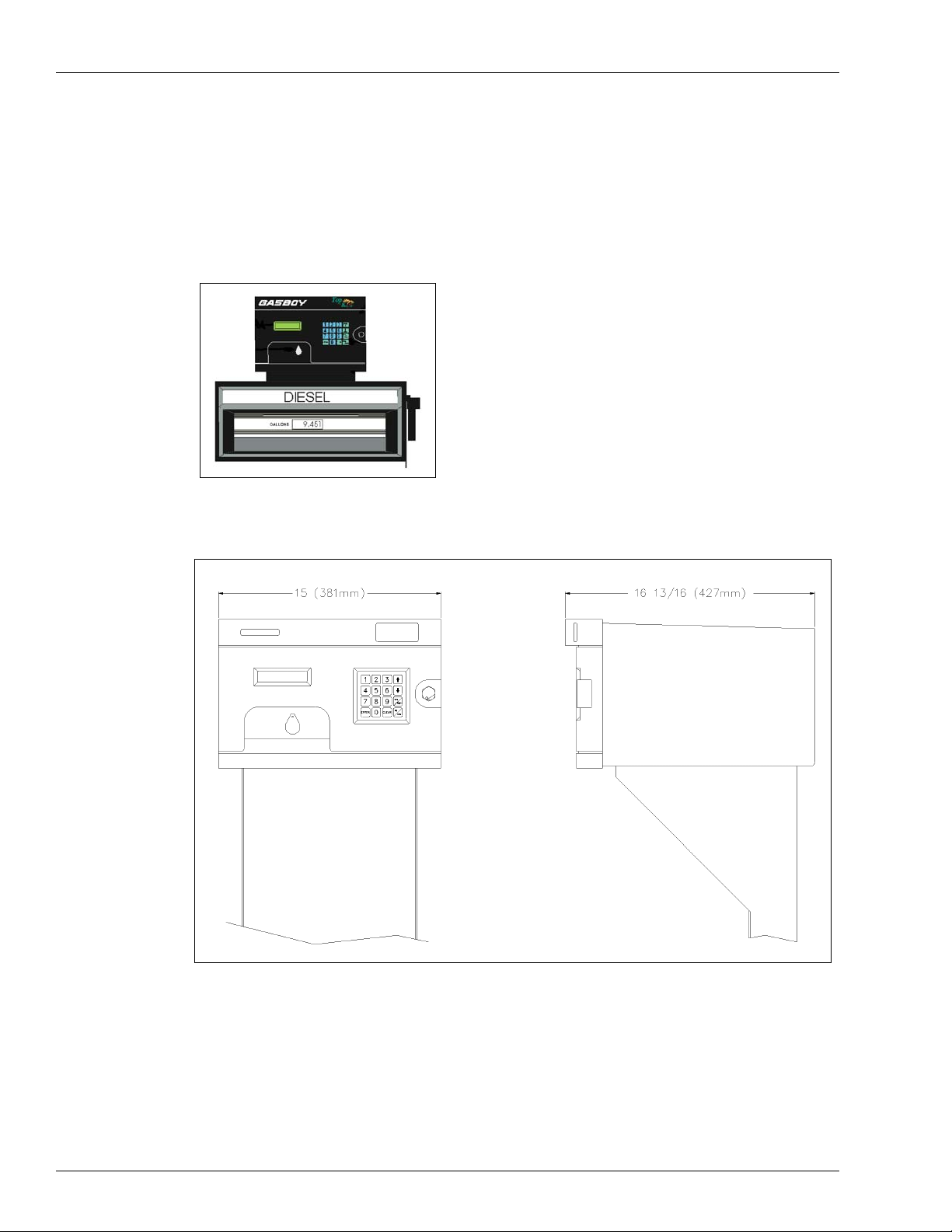
Figure 1-1: Typical TopKAT Installation
Figure 1-2: TopKAT Dimensions
The Gasboy Series 900 TopKAT is a microprocessor-based fuel control and data acquisition
system. The TopKAT system is totally self-contained in a rugged, well-designed, and
attractive weatherized cabinet. It is mounted on one of the following:
• 9800 pump/dispenser
• 9820 ASTRA® pedestal
• Pedestal
Page 2 MDE-4319E TopKAT™ Fuel Management System Installation Manual · August 2008
Page 9

Description Introduction
A standalone TopKAT system can control up to eight electronic hoses or two mechanic al
hoses. A master/satellite option allows multiple units to be linked together, with one acting as
the master controlling unit. If you have the master/satellite option, you can control the
following:
• Up to eight electronic hoses and seven satellite readers
• Up to 16 mechanical hoses (two hoses per TopKAT)
• One 9820 or 9800 single or twin electronic hose and up to 14 mech anical hoses (two hoses
per T o pKAT).
A standalone or master/satellite with a mechanical Pump Control Unit (PCU) option can
control up to eight mechanical hoses (four hoses per PCU and up to two pedestal or wallmounted PCUs).
The TopKAT is equipped with a data key receptacle. Visual prompting messages that are
displayed on the Liquid Crystal Display (LCD) guide the user through the steps required to
activate the pump/dispenser. The display is backlit so that it can be read at night. A 16-posit ion
membrane keypad is provided on the face of the unit to enter data such as Personal
Identification Number (PIN), odometer reading, pump selection, and so on. The unit may also
be equipped with an optional report printer.
The front bezel and rear of the cabinet are hinged doors secured with locks to prohibit
unauthorized access. The front bezel allows access to the optional report printer and paper.
The one-piece hood can be removed for total accessibility during installation and servicing.
When installing the system, ensure that you provide adequate clearance to allow easy access to
both front and rear doors for servicing.
Communication Ports
The TopKAT system contains three asynchronous ports. Typically, Port 1 is used for
communications to a 9800, ASTRA, or Mechanical PCU via RS-485 lines. Ports 2 and 3 can
be set for either RS-232 or RS-422 communications to a data terminal or computer. Refer to
the port wiring diagrams in
of installation. Communication is through direct wire, or by dial-up phone lines using an
optional built-in modem.
If the TopKAT system is equipped with the master/satellite option, the master is the only unit
that will need to have a data communication link. This will collect all transactions and
maintain the complete data base for the entire site. Refer to
on page 19 for more communication requirements.
If the TopKAT is equipped with the wireless option, refer to “Wireless Communications
Installation” on page 121 and MDE-4520 Enhanced Communications Installation Manual.
“Communication Requirements” on page 19 for your specific type
“RS-485 - Master/Satellite Option”
MDE-4319E TopKAT™ Fuel Management System Installation Manual · August 2008 Page 3
Page 10

Introduction Using this Manual
Using this Manual
The TopKAT system can be installed in the following ways:
• Mounted on a pedestal with a Series 9820 ASTRA
• Mounted on a free-standing pedestal for use with mechanical pumps, electronic 9800s or
ASTRAs
• As part of a master/satellite configuration
• Mounted atop a 9800 pump/dispenser
• Mounted on a freestanding pedestal, for use with internal 4-hose Mechanical PCUs or
external wall-mounted 4-hose Mechanical PCUs.
Note: The 4-hose mechanical PCU option is referred to as the Mechanical PCU option in this
manual; the 2-hose Mechanical Interface is called the Mechanical Interface option.
Related Documents
The following manuals provide additional information about the TopKAT Fuel Management
System (FMS).
Document
Number
C35965 TopKAT Host Communications Manual Series 1000/Fleetkey and TopKAT
MDE-4338 TopKAT Operation Manual Series 1000/Fleetkey and TopKAT
MDE-4490 PC/TopKAT User’s Guide CFN Series Controllers and POS
MDE-4520 Enhanced Communications Installation Manual RFID Wireless and TCP/IP Equipment
PT-1957 TopKAT Parts Manual CFN Series Controllers and POS
Title GOLD Library
Warranty
For information on warranty, refer to MDE-4255 Gasboy’s Warranty Policy Statement. If you
have any warranty-related questions, contact Gasboy’s Warranty Department at its
Greensboro location.
Page 4 MDE-4319E TopKAT™ Fuel Management System Installation Manual · August 2008
Page 11
2 – Important Safety Information
Important Safety Information
This section introduces the hazards and safety precautions
associated with installing, inspecting, maintaining or servicing
this product. Before performing any task on this product, read
this safety information and the applicable sections in this
manual, where additional hazards and safety precautions for
your task will be found. Fire, explosion, electrical shock or
pressure release could occur and cause death or serious
injury, if these safe service procedures are not followed.
Preliminary Precautions
You are working in a potentially dangerous environment of
flammable fuels, vapors, and high voltage or pressures. Only
trained or authorized individuals knowledgeable in the related
procedures should install, inspect, maintain or service this
equipment.
Emergency Total Electrical Shut-Off
The first and most important information you must know is
how to stop all fuel flow to the pump/dispenser and island.
Locate the switch or circuit breakers that shut off all power to
all fueling equipment, dispensing devices, and Submerged
Turbine Pumps (STPs).
!
WARNING
!
The EMERGENCY STOP, ALL STOP, and
PUMP STOP buttons at the cashier’s station
WILL NOT shut off electrical po wer to the p ump/
dispenser. This means that even if you activate
these stops, fuel may continue to flow
uncontrolled.
Read the Manual
Read, understand and follow this manual and any other
labels or related materials supplied with this equipment. If you
do not understand a procedure, call a Gasboy Authorized
Service Contractor or call the Gasboy Service Center at 1800-444-5529. It is imperative to your safety and the safety of
others to understand the procedures before beginning work.
Follow the Regulations
Applicable information is available in National Fire Protection
Association (NFPA) 30A; Code for Motor Fuel Dispensing
Facilities and Repair Garages, NFPA 70; National Electrical
Code (NEC), Occupational Safety and Hazard Association
(OSHA) regulations and federal, state, and local codes. All
these regulations must be followed. Failure to install, inspect,
maintain or service this equipment in accordance with these
codes, regulations and standards may lead to legal citations
with penalties or affect the safe use and operation of the
equipment.
Replacement Parts
Use only genuine Gasboy replacement parts and retrofit kits
on your pump/dispenser. Using parts other than genuine
Gasboy replacement parts could create a safety hazard and
violate local regulations.
Safety Symbols and Warning Words
This section provides important information about warning
symbols and boxes.
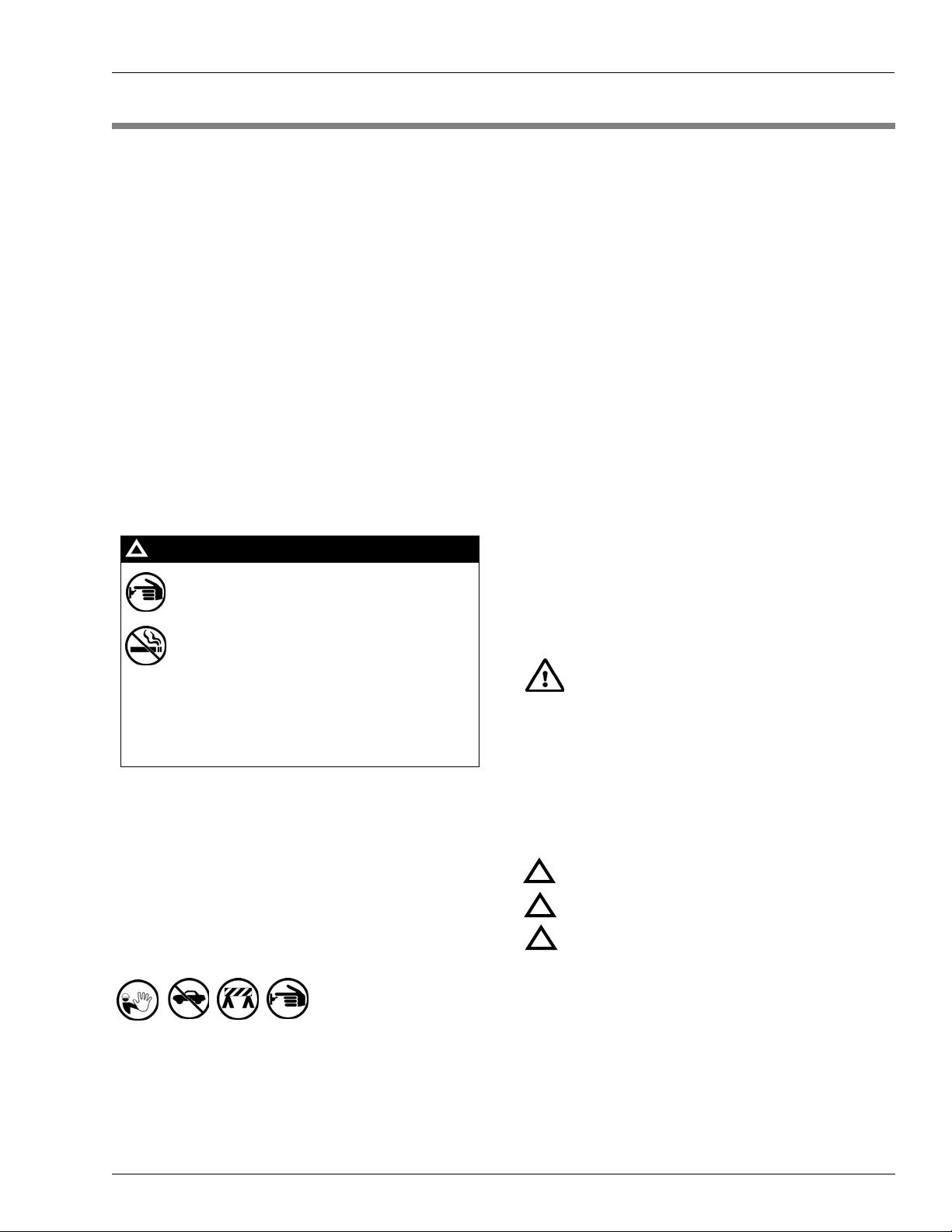
Alert Symbol
You must use the TOTAL ELECTRICAL SHUTOFF in the case of an emergency and not the
console’s ALL STOP and PUMP STOP or
similar keys.
Total Electrical Shut-Off Before Access
Any procedure that requires access to electrical components
or the electronics of the dispenser requires total electrical
shut off of that unit. Understand the function and location of
this switch or circuit breaker before inspecting, installing,
maintaining, or servicing Gasboy equipment.
Evacuating, Barricading and Shutting Off
Any procedure that requires access to the pump/dispenser or
STPs requires the following actions:
• An evacuation of all unauthorized persons and vehicles
from the work area
• Use of safety tape, cones or barricades at the affected
unit (s)
• A total electrical shut-off of the affected unit (s)
This safety alert symbol is used in this manual and
on warning labels to alert you to a precaution which must be
followed to prevent potential personal safety hazards. Obey
safety directives that follow this symbol to avoid possible
injury or death.
Signal Words
These signal words used in this manual and on warning
labels tell you the seriousness of particular safety hazards.
The precautions below must be followed to prevent death,
injury or damage to the equipment:
DANGER: Alerts you to a hazard or unsafe practice
!
which will result in death or serious injury.
WARNING: Alerts you to a hazard or unsafe practice
!
that could result in death or serious injury.
CAUTION with Alert symbol: Designates a hazard or
!
unsafe practice which may result in minor injury.
CAUTION without Alert symbol: Designates a hazard
or unsafe practice which may result in property or
equipment damage
Working With Fuels and Electrical Energy
Prevent Explosions and Fires
Fuels and their vapors will explode or burn, if ignited. Spilled
or leaking fuels cause vapors. Even filling customer tanks will
cause potentially dangerous vapors in the vicinity of the
dispenser or island.
MDE-4319E TopKAT™ Fuel Management System Installation Manual · August 2008 Page 5
Page 12
Important Safety Information
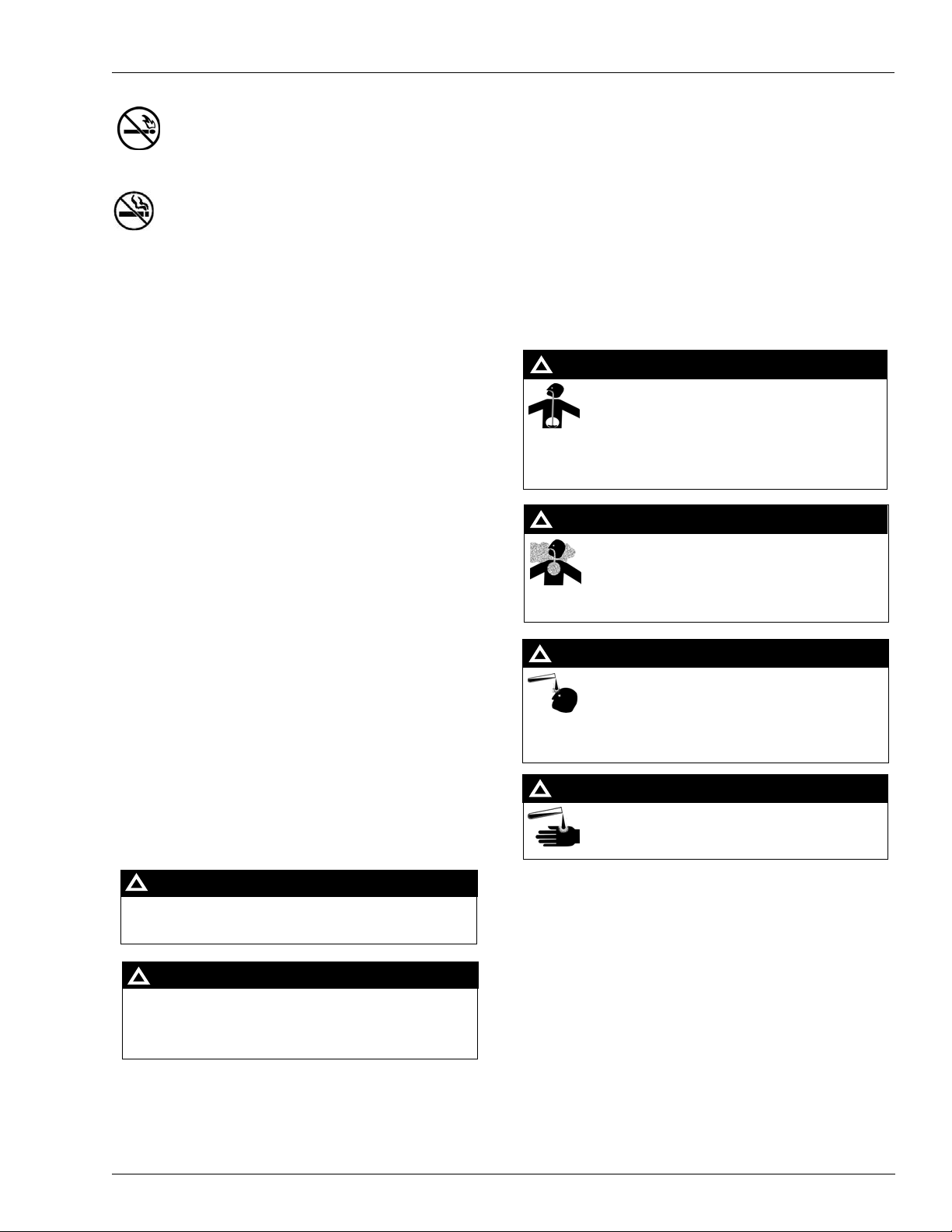
No Open Fire
Open flames from matches, lighters, welding torches
or other sources can ignite fuels and their vapors.
No Sparks - No Smoking
Sparks from starting vehicles, starting or using power tools,
burning cigarettes, cigars or pipes can also ignite fuels and
their vapors. Static electricity, including an electrostatic
charge on your body, can cause a spark sufficient to ignite
fuel vapors. Every time you get out of a vehicle, touch the
metal of your vehicle, to discharge any ele c tro static charge
before you approach the dispenser island.
Working Alone
It is highly recommended that someone who is capable of
rendering first aid be present during servicing. Familiarize
yourself with Cardiopulmonary Resuscitation (CPR) methods,
if you work with or around high voltages. This information is
available from the American Red Cross. Always advise the
station personnel about where you will be working, and
caution them not to activate power while you are working on
the equipment. Use the OSHA Lockout/ Tagout procedures. If
you are not familiar with this requirement, refer to this
information in the service manual and OSHA documentation.
Working With Electricity Safely
Ensure that you use safe and established practices in working
with electrical devices. Poorly wired devices may cause a fire,
explosion or electrical shock. Ensure that grounding
connections are properly made. Take care that sealing
devices and compounds are in place. Ensure that you do not
pinch wires when replacing covers. Follow OSHA Lockout/
Tagout requirements. Station employees and service
contractors need to understand and comply with this program
completely to ensure safety while the equipment is down.
In an Emergency
Inform Emergency Personnel
Compile the following information and inform emergency
personnel:
• Location of accident (for example, address, front/back of
building, and so on)
• Nature of accident (for example, possible heart attack, run
over by car, burns, and so on)
• Age of victim (for example, baby, teenager, middle-age,
elderly)
• Whether or not victim has received first aid (for example,
stopped bleeding by pressure, and so on)
• Whether or not a victim has vomited (for example, if
swallowed or inhaled something, and so on)
WARNING
!
Gasoline ingested may cause unconsciousness
and burns to internal organs.
Do not induce vomiting.
Keep airway open.
Oxygen may be needed at scene.
Seek medical advice immediately.
WARNING
!
Gasoline inhaled may cause unconsciousness
and burns to lips, mouth and lungs.
Keep airway open.
Seek medical advice immediately.
WARNING
!
Gasoline spilled in eyes may cause burns to eye
tissue.
Irrigate eyes with water for approximately 15
minutes.
Seek medical advice immediately.
Hazardous Materials
WARNING
Some materials present inside electronic enclosures may
present a health hazard if not handled correctly. Ensure that
you clean hands after handling equipment. Do not place any
equipment in the mouth.
!
WARNING
The pump/dispenser contains a chemical known to the
State of California to cause cancer.
!
Gasoline spilled on skin may cause burns.
Wash area thoroughly with clear water.
Seek medical advice immediately.
IMPORTANT: Oxygen may be needed at scene if gasoline
has been ingested or inhaled. Seek medical advice
immediately.
Lockout/Tagout
WARNING
!
Lockout/Tagout covers servicing and maintenance of
machines and equipment in which the unexpected
The pump/dispenser contains a chemical known to the
State of California to cause birth defects or other
reproductive harm.
energization or start-up of the machine(s) or equipment or
release of stored energy could cause injury to employees or
personnel. Lockout/Tagout applies to all mechanical,
hydraulic, chemical or other energy, but does not cover
electrical hazards. Subpart S of 29 CFR Part 1910 - Electrical
Hazards, 29 CFR Part 1910.333 contains specific Lockout/
Tagout provision for electrical hazards.
Page 6 MDE-4319E TopKAT™ Fuel Management System Installation Manual · August 2008
Page 13
Hazards and Actions
Important Safety Information
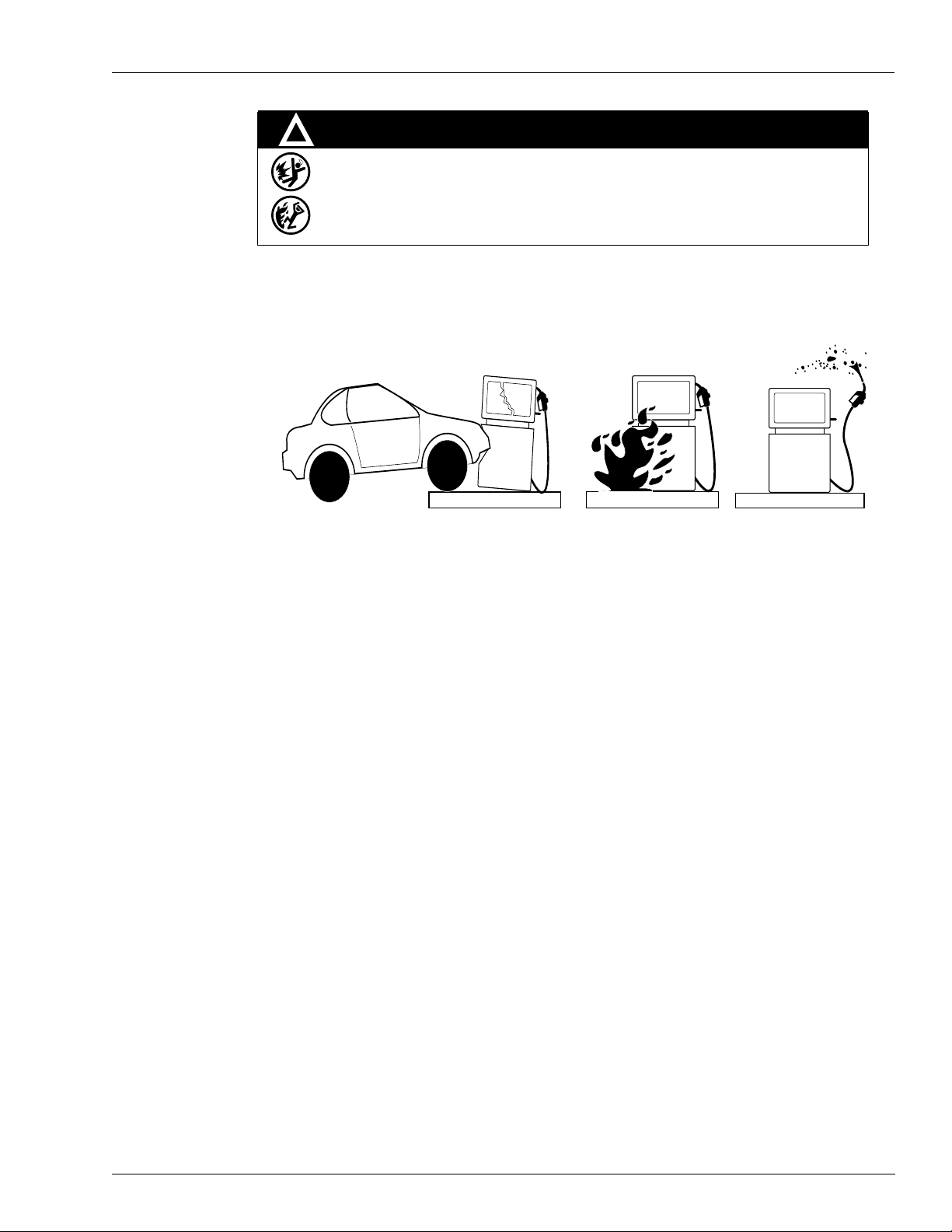
!
WARNING
Spilled fuels, accidents involving pumps/dispensers, or uncontrolled fuel flow create a
serious hazard.
Fire or explosion may result, causing serious injury or death.
Follow established emergency procedures.
The following actions are recommended regarding these hazards:
Collision of a Vehicle with Unit Fire at Island Fuel Spill
• Do not go near a fuel spill or allow anyone else in the area.
• Use station EMERGENCY CUTOFF immediately. Turn off all system circuit breakers to the
island(s).
• Do not use console E-STOP, ALL STOP and PUMP STOP to shut o ff power. These keys do not
remove AC power and do not always stop product flow.
• Take precautions to avoid igniting fuel. Do not allow starting of vehicles in the area. Do not allow
open flames, smoking or power tools in the area.
• Do not expose yourself to hazardous conditions such as fire, spilled fuel or exposed wiring.
• Call emergency numbers.
MDE-4319E TopKAT™ Fuel Management System Installation Manual · August 2008 Page 7
Page 14

Important Safety Information
This page is intentionally left blank.
Page 8 MDE-4319E TopKAT™ Fuel Management System Installation Manual · August 2008
Page 15

FCC Part 15 FCC and DOC Customer Information
3 – FCC and DOC Customer Information
Both the US Federal Communications Commission (FCC) and the Canadian Department of
Communication (DOC) require that specific information be supplied to the users of any
equipment that may emit radio frequency energy. Read the following information for details.
FCC Part 15
This equipment has been tested and found to comply with the limits for a Class A digital
device, pursuant to Part 15 of FCC rules. These limits are designed to provide reasonable
protection against harmful interference when the device is operated in a commercial
environment. This equipment generates, uses, and can radiate radio frequency energy and, if
not installed in accordance with the instruction manual, may cause harmful interference to
radio communications. Operation of this equipment in a residential area is likely to cause
harmful interference, in which case, users will be required to correct the interference at their
own expense.
FCC Part 68
General Requirements for All Equipment
• This equipment complies with Part 68 of the FCC rules. The Gasboy Internal Modem is
contained within a Gasboy FMS. On the outside of the rear access door of the FMS is a
label that contains, among other information, the FCC registration number and Ringer
Equivalence Number (REN) for this equipment. If requested, this information must be
provided to the telephone company.
• The Gasboy Internal Modem should be connected to a USOC RJ-11C jack.
• An FCC-compliant telephone cord and modular plug is provided with the equipment. This
equipment is designated to be connected to the telephone network or premises wiring
using a compatible modular jack, which is Part 68 compliant.
• The REN is used to determine the quantity of devices that may be connected to the
telephone line. Excessive RENs on the telephone line may result in the device not ringing
in response to an incoming call. In most, but not all areas, the sum of RENs should not
exceed five (5.0). To be certain of the number of devices that may be connected to a line,
as determined by the total RENs, contact the local telephone company.
• If the Gasboy Internal Modem causes harm to the telephone network, the telephone
company will notify you in advance that temporary discontinuance of service may be
required. But if the advance notice is not practical, the telephone company will notify the
customer as soon as possible. Also, you will be advised of your right to file a complaint
with the FCC if you believe it is necessary.
• The telephone company may make changes in its facilities, equipment, operations or
procedures that could affect the operation of the equipment. If such a case, the telephone
company will provide advance notice for you to make necessary modifications to maintain
uninterrupted service.
MDE-4319E TopKAT™ Fuel Management System Installation Manual · August 2008 Page 9
Page 16

FCC and DOC Customer Information FCC Part 68
• If trouble is experienced with the Gasboy Internal Modem, contact Gasboy at
1-800-444-5529 for repairs or warranty information. If the equipment is causing harm to
the telephone network, the telephone company may request that you disconnect the
equipment until the problem is resolved.
• The Gasboy Internal Modem does not have any easily repairable or replaceable parts.
Contact Gasboy in case you are experiencing trouble.
• The equipment cannot be used on the public coin phone service provided by the telephone
company . Connection to the party line service is subject to state tariffs. (Contact your state
Public Utility Commission, Public Service Commission or Corporation Commission for
information).
DOC Certification
Industry Canada Ringer Equivalence Number Notice
The Canadian Department of Communications label identifie s the certified equipment. This
certification indicates that the equipment meets certain telecommunications network
protective, operational, and safety requirements. The department does not guarantee that the
equipment will operate to the user's satisfaction.
Before installing this equipment, you should ensure that it is permissible to be connected to the
facilities of the local telecommunications company. The equipment must also be installed
using an acceptable method of connection. In some cases, the company's inside wiring
associated with a single line individual service may be extended by means of a certified
connector assembly (telephone extension cord). The customer should be aware that
compliance with the above condition may not prevent degradation of the service in some
situations.
Repairs to the certified equipment should be made by an authorized maintenance facility
designated by the supplier. Any repairs or alterations made to this equipment, or equipment
malfunctions may give the telecommunications company cause to request you to disconnect
the equipment.
You should ensure for your protection that the ground connections of the power utility,
telephone lines and internal metallic water pipe system are connected together. This
precaution may be particularly important in rural areas.
!
CAUTION
Users should not attempt to make such connections themselves and should contact the
electric inspection authority or electrician, as appropriate.
The REN assigned to each terminal device denotes the percentage of the total load to be
connected to a telephone loop that is used by the device, to prevent overloading. The
termination on a loop may consist of any combination of devices subject only to the
requirement that the total of the REN of all devices does not exceed five.
The REN for the Gasboy Internal Modem is 0.8B.
Page 10 MDE-4319E TopKAT™ Fuel Management System Installation Manual · August 2008
Page 17
Rules for Proper Installation General Installation
4 – General Installation
Rules for Proper Installation
!
WARNING
To reduce the risk of electrical shock when servicing, turn off all power to the pump/remote
dispenser. In submersible pump applications, turn off all power to the submersible pump
and any other remote dispensers that use the submersible pump. AC power can feed back
into a shut-off remote dispenser when dispensers share a common submersible pump or
starter relay.
!
AVERTISSEMENT
Pour réduire le risque de choc électrique lors de l'entretien/révision, coupez totalement le
courant à la pompe/distributeur éloigné. Dans les applications de pompe immersible, coupez
totalement le courant à la pompe immersible et tous autres distributeurs éloigné qui utilisent la
pompe immersible. Le courant alternatif peut alimenter de nouveau un distributeur éloigné à
l'arrêt quand les distributeurs partagent une pompe immersible commune ou un relais de
démarrage.
To ensure proper installation, follow these rules:
• Read this entire manual before starting installation.
• Internationally and domestically: All wiring is to be installed and used in accordance with
all applicable national, state, and local building/fire/electrical codes. Additionally, in the
USA, installations must comply with the National Electrical Code (NFPA 70), NFPA 30,
and the Automotive and Marine Service Station Code (NFPA 30A) codes and regulations.
Canadian installations must comply with the Canadian Electrical Code.
• All wiring must be in a threaded, rigid, metal conduit to provide the necessary shielding.
DO NOT use a PVC conduit.
• High-voltage AC and low-voltage DC must not be combined in a common conduit,
Junction box, or wire trough unless the cable is used as specified in
“RS-422 - SHMs” on
page 22.
• Power for the TopKAT system (when used with a mechanical interface), da ta terminal,
and external modem must come from a separate, dedicated, circuit breaker.
• The TopKAT system and peripheral equipment must be properly grounded.
• Use terminal connectors on stranded wire.
• Test pumps in the manual override position prior to the startup of the system.
• DO NOT turn on the system power switch located in the head assembly. Power will be
applied to the system by the person performing the system startup. Turning on this switch
prematurely may result in damage to the system and may void your warranty.
Note:When the TopKAT system is supplied with a Mechanical Pump Interface (2-hose
Mechanical or 4-hose PCU), it is necessary to turn on system power in order to test.
Refer to
“Testing” on page 125 for more details.
• Check through all boxes and cartons for manuals, cables, connectors, and so on before
disposing them off.
MDE-4319E TopKAT™ Fuel Management System Installation Manual · August 2008 Page 11
Page 18

General Installation Component Location and Installation Specifications
Component Location and Installation Specifications
Careful planning for the layout of the site will help eliminate possible problems with the
startup of your system and will ensure continued, reliable system operation.
System
Regardless of your installation option, the TopKAT system must be located on the fuel island.
Data Terminal
°
The unit has been designed to withstand an environment of -22
F to 122° F (-30
95% relative humidity (non-condensing). When mounting the un it, a minimum clearance of 18
inches between the post and any of the pumps or dispensers must be maintained. This
clearance meets the NFPA 30A and NFPA 70 re quirements and allows room for the wiring
and maintenance of the system. Adequate clearance around the head of the unit is important to
provide room for the maintenance of the system. A minimum of 14 inches of clearance from
the rear of the unit must be provided to allow the rear door to open.
When a data terminal is used with the system it must be UL-listed and should be located in a
clean, office type of environment. Do not install the data terminal over a hazardous location.
Data terminals supplied by Gasboy have an operative temperature range of 32
(0° C to 40° C). Locating the terminal in a dirty environment may cause premature failure.
Refer to
“Port Communication Wiring” on page 28 for your installation type to connect the
data terminal.
°
C to 50° C),
°
F to 104° F
External Modem
When an external modem is used with the system it must be UL-listed and should be located in
an office type of environment. However, if this is not possible, it should be housed in a
protective enclosure. Do not install the modem over a hazardous location. External modems
supplied by Gasboy have an operative temperature range of 32
type of phone line required for communication via an external modem is dependant on the
type of modem used and the method of communication desired. Consult the manual that
comes with the modem for specific requirements. Refer to
page 28 for your installation type to connect the external modem.
°
F to 104° F (0° C to 40° C). The
“Port Communication Wiring” on
Page 12 MDE-4319E TopKAT™ Fuel Management System Installation Manual · August 2008
Page 19

Component Location and Installation Specifications General Installation
Internal Modem
When the TopKAT system is equipped with the optional internal modem, the Port 3
communication is routed through the modem in place of being wired at the DC Junction box.
Jumper K2 should be removed. Refer to
jumpers K1 and K2. The phone line for the internal modem can be installed in the DC conduit.
If you are installing the phone line in a DC conduit, the cable must be two twisted-pair
shielded cables as specified in
“Communication Requirements” on page 19 and the shield
drain wire must be connected to the system AC ground. Check with your local phone company
for proper installation of the phone line.
If you order your TopKAT system with an optional internal modem, the modem is mounted
within the TopKAT system at the factory and power for the modem is supplied by the
TopKAT system. The 2400 baud modem is designed for 300, 1200, or 2400 baud, full duplex,
asynchronous communication. The 33600 baud modem is designed for 1200, 2400, or 9600
baud, full duplex, asynchronous communication. This modem meets or exceeds the direct
connection registration requirements of the FCC rules. The modem will connect directly
through a phone line supplied by the phone company. The customer is required to order this
phone line and have it installed.
To order this equipment from the phone company, specify:
“Terminal Block ID” on page 24 for the location of
1 The registration number of 6BHUSA-2479 3-DT-E.
2 The data transmission rate of 300 baud, 1200 baud, 2400 baud, or 9600 baud.
3 The Bell equivalent of 103J/212A.
Power Conditioner
When used, a UL-listed power conditioner helps provide clean power to the TopKAT system.
Poor power conditions are a key cause to system malfunction or failure. The power
conditioner provides transient and common mode protection for the TopKAT system,
although it cannot totally compensate for extremely poor power conditions. The power
conditioner must be located in an area protected from direct contact with the weather
(typically near the system circuit breakers) and should be no further than 50 feet from the
TopKAT system for optimum protection. It must not be used over a hazardous location.
When used with a TopKAT system that is installed on a 9800 or ASTRA, the Micro Feed line
from the pump/dispenser is routed through the power conditioner and then to the breaker . W ith
a mechanical installation, the TopKAT system is directly connected to the power conditioner
and then to the breaker. The power conditioner is designed for an operating temperat ure range
of -20
°
C to 48
°
C.
MDE-4319E TopKAT™ Fuel Management System Installation Manual · August 2008 Page 13
Page 20

General Installation Conduit Layout/Installation Specifications
Conduit Layout/Installation Specifications
• Internationally and domestically: All wiring must be installed and used in accordan ce with
all applicable national, state, and local building/fire/electrical codes. Additionally, in the
USA, installations must comply with the National Electrical Code (NFPA 70), NFPA 30,
and the Automotive and Marine Service Station Code (NFPA 30A) codes and regulations.
Canadian installations must comply with the Canadian Electrical Code.
• All peripheral equipment connected to the RS-232 ports must be listed, have an
Electronics Industrial Association (EIA) standard RS-232 communications protocol and
not be installed over a hazardous location.
• Power for the data terminal and external modem must come from a separate circuit
breaker rated at no less than 10A.
• All conduits must be made of metal to provide the necessary shielding.
• Use the Conduit Size Chart to determine the proper conduit size.
• RS-232 communication must not exceed 100 feet. RS-232 communication wires must be
in a separate metal conduit away from AC wires.
• For communication distances exceeding 100 feet, you must use a Gasboy RS-422 Short
Haul Modem.
• It is recommended that high voltage AC power wires be installed in a separate conduit,
away from the low voltage DC signal wires. However, if AC and DC wires share the
conduit, communication wiring must use the cable specified in “RS-422 - SHMs” on
page 22.
• DC RS-422 communication wires can be combined in the same conduit.
• When using the master/satellite configuration, the maximum field wiring cable length
between the first and last unit must not exceed 1500 feet (455 m). It is recommended that
high voltage AC wires be installed in a separate conduit, away from the low voltage DC
signal wires. However, if AC and DC wires share the conduit, communication wiring must
use the cable specified in
“Communication Requirements” on page 19.
Conduit Requirements
All wiring (AC and DC) connecting different components of the Gasboy FMS must be
installed in threaded, rigid, metal conduit except as noted in
on page 19 and “RS-422 - SHMs” on page 22. PVC IS NOT ACCEPTABLE. Components of
the system include pumps, dispensers, submersible pumps, submersible starter relays, circuit
breaker panels, optional wall-mount PCUs and the TopKAT system. Communications
equipment signal wires must also be run in the metal conduit, except for RS-422 wiring, as
noted in
Communication equipment signal wires must also be run in metal conduits. High-voltage
(AC) and low-voltage (DC) must not be combined in a common conduit, Junction box, or wire
trough unless the cable is used as specified in
All conduits must be connected to the TopKAT pedestal through the holes and knockouts
provided by the factory. Do not make any other holes in this unit. If you must make holes at
locations other than those provided, contact Gasboy for approval.
Page 14 MDE-4319E TopKAT™ Fuel Management System Installation Manual · August 2008
“Communication Requirements” on page 19.
“Communication Requirements” on page 19.
“Communication Requirements”
Page 21

Conduit Requirements General Installation
All wiring and conduit runs must conform to all building/fire codes, all Federal, State, and
Local codes, the National Electrical Code (NFPA 70), NFPA 30, and the Automotive and
Marine Service Stations Code (NFPA 30A). Canadian users must also comply with the
Canadian Electrical Code.
Use the tables below as a guideline to determine the proper conduit sizes for the Gasboy
TopKAT FMS. When planning the o r ientation of wiring runs, follow the applicable Gasboy
wiring diagram and consider the layout of components at the site. Long runs or a large number
of bends may require you to increase the conduit size over what is listed here.
To determine the conduit size required, use the “THHN/THWN Wire Areas” table to find the
area for each wire gauge. Add up all wire areas. Use the “Areas of Trade Size Conduit” table
to select the smallest number in the 25% fill area (based on NEC 501-1) that comes closest
without exceeding the total wire area.
THHN/THWN Wire Areas
Gauge
18 .090 2.29 .007 4.1
16 .104 2.64 .009 5.5
14 .118 2.95 .011 6.8
12 .135 3.43 .014 9.2
10 .169 4.29 .022 14.5
8 .216 5.49 .037 23.7
6 .259 6.60 .053 34.2
4 .331 8.41 .086 55.5
3 .359 9.14 .102 65.6
2 .394 10.01 .122 78.7
1063A .417 10.59 .137 88.4
Inches Millimeters Inches Millimeters
Diameter Area (square units)
Areas of Trade Size Conduit
Internal Diameter Area (square units) Fill Area (square units) 25% fill
Trade Size
1/2 .629 16 .303 196 .076 49
3/4 .826 21 .532 343 .133 86
1 1.063 27 .862 556 .215 139
1-1/4 1.378 35 1.50 968 .375 242
1-1/2 1.614 41 2.04 1314 .509 329
2 2.087 53 3.36 2165 .839 541
MDE-4319E TopKAT™ Fuel Management System Installation Manual · August 2008 Page 15
Inches Millimeters Inches Millimeters Inches Millimeters
Page 22

General Installation Power Requirements
Power Requirements
AC Power to the TopKAT System
When mounted to a 9800 or ASTRA, AC power for the TopKAT system is supplied from the
same power source used to power the 9800 or ASTRA Micro Feed. A wiring cable for AC
power from the 9800 or ASTRA to the TopKAT is supplied with the TopKAT. Refer to
“ASTRA to T opKAT Cabling” on page 27 for more information.
When mounted on a pedestal, AC power for the TopKAT system must come from a separate,
dedicated circuit breaker. No other equipment, including the system's pumps or dispensers,
may be powered from this breaker.
When the TopKAT system is pedestal-mounted with internal PCUs, AC power for the
TopKAT system must be supplied from the same power source used to power the PCUs. A
wiring cable for AC power from the TopKAT system to the PCUs is supplied. When the
TopKAT system is pedestal-mounted but is being used with wall-mounted PCUs, the AC
power for the TopKAT system and PCUs must come from a separate, dedicated circuit
breaker. No other equipment, including the system's pumps and dispensers may be powered
from this breaker.
TopKAT Peripheral Equipment
When used with a 9800 or ASTRA, AC power for the data terminal or external modem must
come from a separate, dedicated circuit breaker. No other equipment, including the system's
pump or remote dispenser control may be powered from this breaker. However, for 9800 and
ASTRA applications, it is acceptable to power the data terminal or external modem from the
breaker that supplies power to the electronic register (Micro Feed on 9800 or ASTRA). This
breaker is the same one that supplies power to the TopKAT system. Whenever possible, one
breaker should be used to supply the Micro Feed and the data terminal or external modem.
However, it is acceptable to supply power to both from multiple breakers within the same
breaker panel and the same phase of power. When necessary, power for the data terminal or
modem may be supplied from a separate, dedicated breaker located in a different breaker
panel.
When used with a pedestal TopKAT system, power for a data terminal or external modem can
come from the same breaker as the TopKAT system.
The system requires 115 VAC + 10% 47-63 Hz, or optional 230 VAC + 10% 47-63 Hz of
power. The system draws a maximum of 95 Watts.
Grounding
Proper system grounding is an extremely important part of system installation. As with the AC
power, the grounds for all system components should return to the same breaker panel. This
helps you to assure a common ground throughout the system, which is necessary for protection
of the RS-485 data loop circuitry. Grounds for all system devices should be wired to the
breaker panel ground bus bar, which in turn should be grounded to a ground rod. A conduit
ground does not provide sufficient ground. It is recommended that the neutral and ground bus
bars be bonded together when it is not prohibited by local codes.
Page 16 MDE-4319E TopKAT™ Fuel Management System Installation Manual · August 2008
Page 23

Wire Size General Installation
Suction Pumps
The TopKAT system, with Mechanical Interface or Mechanical PCU options, is capable of
directly driving pump motors up to 3/4 HP at 115 VAC or 1-1/2 HP at 230 VAC. A starter
relay must be used with pump motors that exceed this limitation. A separate circuit breaker
should be supplied for each pump to meet the current requirements and to allow isolated
control with the circuit breaker panel in case of problems.
Dispensers
The TopKAT system with the Mechanical Interface option is capable of directly driving
submersible pumps up to 3/4 HP at 115 VAC or 1-1/2 HP at 230 VAC. A dispenser with a
submersible pump exceeding this limitation requires the use of a submersible starter relay. A
separate circuit breaker should be supplied for each dispenser in cases where it will directly
drive the submersible pump. Dispensers may be grouped together on a single breaker when the
submersible pump has its own breaker . It is recommended that no mo re than two dispen sers be
powered from one breaker to maintain isolated control with the circuit breaker panel in case of
problems.
Wire Size
A wiring cable for AC power from the 9800 or ASTRA to the TopKAT system is supplied
with the TopKAT system. If you are wiring a pedestal TopKAT system or wall-mount
Mechanical PCUs, the AC power wire size must be 14 AWG or larger for runs of up to 300
feet from the breaker panel to the system. Sites with distances over 300 feet must use 12 A WG
wire or larger.
The AC wire size for power of the system data terminal or external modem must be 14 AWG
or larger. This gauge of wire will be sufficient for runs of up to 300 feet (91m) from the
breaker panel to the system. Components with distances over 300 feet (91m) must use 12
AWG wire or larger. All wires should be stranded.
The specifications for the communication wire/cable size can be found in RS-485
“Communication Requirements” on page 19 and/or “RS-422 - SHMs” on page 22 in this
chapter.
MDE-4319E TopKAT™ Fuel Management System Installation Manual · August 2008 Page 17
Page 24

General Installation Wire Size
Mechanical Interface Option
The AC wire size for a suction pump is dependent on the HP rating of the pump motor, the
voltage at which the pump will be operated (115/230), and the distance from the circuit
breaker panel to the pump. The chart below may be used as a guide to select the proper size
wire according to the specific installation requirements. The wire size for the Reset Complete
from the pump should be 14 AWG. All wires should be stranded.
The AC wire size for the control lines of a dispenser should be 12 AWG. These control lines
supply power for the reset mechanism, solenoid valve, and submersible starter relay (when the
submersible pump is not directly powered by the dispenser). The wire size for the submersible
pump power depends on the HP rating of the pump motor, the voltage at which it will be
operated (115/230), and the distance from the circuit breaker to the pump. Use the following
table as a guide to select the proper wire size according to specific installation requirements.
The wire size for the Reset Complete from the dispenser should be 14 AWG. All wires should
be stranded.
The DC wire size for the pulser must be 18 AWG (when they are used). Shielded cables, as
described in
The DC wire size for RS-422 lines should be 18 AWG and meet the specifications outlined in
“Communication Requirements” on page 19.
“Pulser Wiring Notes” on page 50 allows pulser lines to run with AC wires.
Refer to “Communication Requirements” on page 19 to determine the wire size and type for
communication wiring of your specific application.
115 Volt Wire Gauge Sizes per Feet/Meters of Run (Note)
Motor H.P.
1/2 14 12 10 8 8 8 8
3/4 14 12 10 8 8 6 4
Note: For runs over 300 feet, use the relay at the motor location.
25’
7.6M
50’
15.2M
100’
30.5M
150’
45.7M
200’
61M
250’
76.2M
300’
91.4M
230 Volt Wire Gauge Sizes per Feet/Meters of Run (Note)
25’
Motor H.P.
1/2 14 12 12 12 10 10 10
3/4 14 12 12 10 10 10 8
1-1/2 12 12 10 10 8 8 8
Note: For runs over 300 feet, use relays at the motor location.
7.6M
50’
15.2M
100’
30.5M
150’
45.7M
200’
61M
250’
76.2M
300’
91.4M
Page 18 MDE-4319E TopKAT™ Fuel Management System Installation Manual · August 2008
Page 25

Communication Requirements General Installation
Communication Requirements
The TopKAT system utilizes RS-485, RS-232, and RS-422 modes of communication for
communicating to the ASTRA, 9800, Mechanical PCUs and peripheral equipment. The
TopKAT has three ports:
• Port 1 is an RS-485 port that is dedicated to communicate with the ASTRA or satellite
TopKAT system.
• Ports 2 and 3 are configurable for either an RS-232 or RS-422 for communication with a
data terminal, modem, or PC.
Phone line (modem) communication may also be used when remote communication to the site
is desired. If a TopKAT internal modem is used, Port 3 is not available for external
communication wiring. The specific requirements for each of these modes of communication
are listed below.
RS-485 - ASTRA and Mechanical PCUs
RS-485 wiring is used for communication between the TopKAT system, ASTRA, and
Mechanical PCUs. This communication takes place over the RS-485 wiring that is supplied
with the TopKAT when the TopKAT system is mounted on an ASTRA or the Mechanical
PCU is mounted in the TopKAT pedestal.
RS-485 - Master/Satellite Option
The master/satellite option uses four wires to operate a full-duplex RS-485 communication
loop. Ports 2 and 3 of the master can be set for either RS-232 or RS-422 communications to a
data terminal or computer or used to communicate with an optional built-in modem.
• All wiring is to be installed and used in accordance with all building/fire codes, Federal,
State and Local codes, National Electrical Code (NFPA 70), NFPA 30, and Automotive
and Marine Service Station Code (NFPA 30A) codes and regulations. Wiring must also
conform to the wiring diagram supplied with the pump/remote dispenser. Canadian users
must comply with the Canadian Electrical Code.
• Power: The AC power for the short haul modem should come from the same breaker that
supplies the peripheral device or the system (Micro Feed).
• Cable: A twisted-pair shielded cable is highly recommended for RS-485 wiring. Although
it is recommended that wires be run in a conduit away from AC wires, they can be
combined in the same conduit with AC wires, provided that a UL-listed cable with the
following specifications is used:
- Conductor: 18 AWG stranded wire; one twisted-pair
- Shield: Foil-wrapped 100% coverage and/or tinned copper braid 90% coverage
- Drain Wire: Stranded, tinned copper, 20 AWG or larger/or braided shield
- Voltage Rating: Maximum operating voltage of 600 V
- Environmental: Gas and oil-resistant; suitable for wet or dry locations.
Gasboy can supply Belden® 1120A (part number C09672) that is a UL-listed, 2-conductor
cable that meets the requirements listed above.
Belden 1120A is UL-listed but not CSA-listed.
Cables with a voltage rating of less than 600 V must be installed in a conduit away from
all AC wires.
MDE-4319E TopKAT™ Fuel Management System Installation Manual · August 2008 Page 19
Page 26

General Installation Communication Requirements
• Conduit: When you use the recommended shielded twisted-pair cable, RS-485 wires can
be run with AC wires in the metal conduit. The shield drain wire must be connected to the
system AC ground. Only AC wires for the system and pumps can be installed in the AC
conduit. Do not run the cable outdoors without the use of metal conduit. Do not run this
cable overhead when outdoors.
The cable can be run indoors without the use of a metal conduit. The shield drain wire
must be connected to the system AC ground (at one end only).
If you use cables other than the ones that are recommended above, the RS-485 field wires
must be installed in a metal conduit away from AC wires.
• Distance: The maximum overall field wiring cable length between all units must not
exceed 1500 feet (455 m).
RS-485 - Standalone To pKAT System or Wall-Mount PCU
When the TopKAT system must communicate to a 9800 or wall-mount PCU through Port 1
(RS-485) of the TopKAT system and the TopKAT is not directly mounted on the 9800, the
appropriate interconnect cable must be used. It must always be used in this configuration. A
distance of up to 1500 feet (455 m) is allowed. Refer to “Port Communication Wiring” on
page 28 for the wiring diagrams.
Installation Requirements
• Internationally and domestically: All wiring is to be installed and used in accordance
with all applicable national, state and local building/fire/electrical codes. Additionally, in
the USA, installations must comply with the National Electrical Code (NFPA 70), NFPA
30, and the Automotive and Marine Service Station Code (NFPA 30A) codes and
regulations. Canadian installations must comply with the Canadian Electrical Code.
• Cable: A twisted-pair shielded cable is highly recommended for RS-485 wiring. Although
it is recommended that wires be run in a conduit away from AC wires, they can be
combined in the same conduit with AC wires, provided that a UL-listed cable with the
following specifications is used:
- Conductor: 18 AWG stranded wire; one twisted-pair
- Shield: Foil-wrapped 100% coverage and/or tinned copper braid 90% coverage
- Drain Wire: Stranded, tinned copper, 20 AWG or larger/or braided shield
- Voltage Rating: Maximum operating voltage of 600 V
- Environmental: Gas and oil-resistant; suitable for wet or dry locations.
Gasboy can supply Belden 1120A (part number C09672) which is a UL-listed,
2-conductor cable that meets the requirements listed above.
Note: Belden 1120A is UL-listed but not CSA-listed.
Cables with a voltage rating of less than 600 V must be installed in a conduit away from
all AC wires.
• Conduit: When you use the recommended shielded twisted-pair cable described
previously, RS-485 wires can be run with AC wires in a metal conduit. The shield drain
wire must be connected to the system AC ground. Only AC wires for the system and
pumps can be installed in the AC conduit. Do not run the cable outdoors without the use of
a metal conduit. Do not run this cable overhead when outdoors.
Page 20 MDE-4319E TopKAT™ Fuel Management System Installation Manual · August 2008
Page 27
Communication Requirements General Installation
The cable can be run indoors without the use of a metal conduit. The shield drain wire
must be connected to the system AC ground (at one end only).
If you are using a cable other than what was recommended previously, the RS-485 field
wires must be installed in a metal conduit away from AC wires.
• Distance: The maximum field wiring cable length must not exceed 1500 feet (455 m).
RS-232
RS-232 wiring can be used for communication between the TopKAT system and EIA RS-232
compatible peripheral devices (CRT/printer , modem, and so on). The remote end of the wiring
can be terminated with either an RS-232D connector or a Gasboy termination box. You must
follow these installation requirements when installing the RS-232 communication lines:
• All peripheral equipment connected to the RS-232 ports must be UL-listed, have an EIA
standard RS-232 communication protocol and not be installed over a hazardous location.
• Distance: The following distances must be adhered to when installing the RS-232
communication lines:
- 1 - 100 feet (1 - 31 meters): RS-232 can be directly connected to a peripheral device.
- 101 - 1500 feet (32 - 455 meters): RS-422 and Gasboy Short Haul Modem (SHM) are
required. Refer to “RS-422 - SHMs” on page 22 for details.
• Conduit: All direct connect RS-232 cables over 15 feet (5 m) must be in a metal conduit
away from any AC wires. For conduit requirements of SHMs, Refer to the installation
sheet that applies to the device being used.
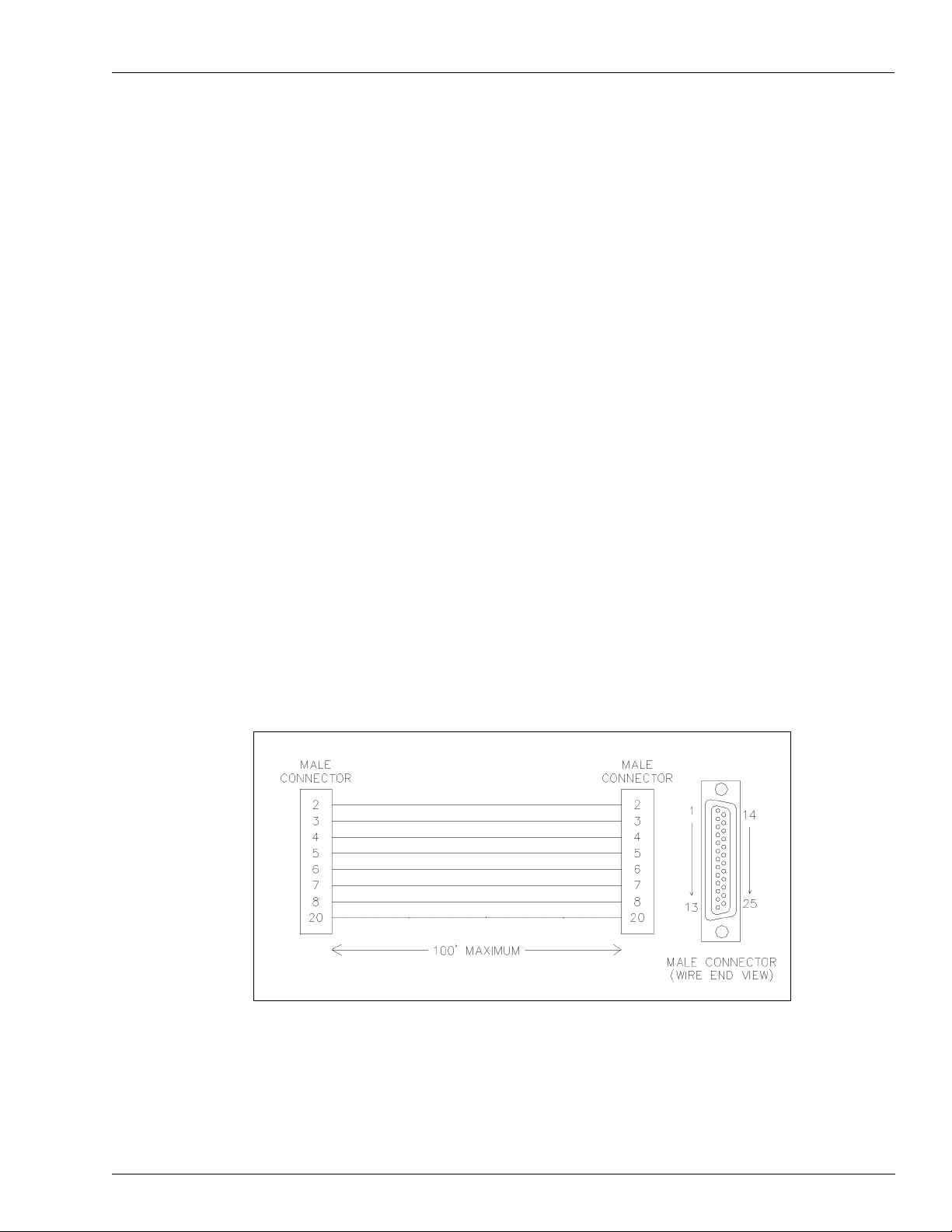
• Cables: RS-232 cables can either be purchased from Gasboy or made by the installer. The
type of cable needed will vary according to the device it connects. When making cables,
the wire used must be stranded and not a solid core.
Figure 4-1: RS-232 1:1 Cable (Part Number C04549: 8 feet M/M)
MDE-4319E TopKAT™ Fuel Management System Installation Manual · August 2008 Page 21
Page 28
General Installation Communication Requirements
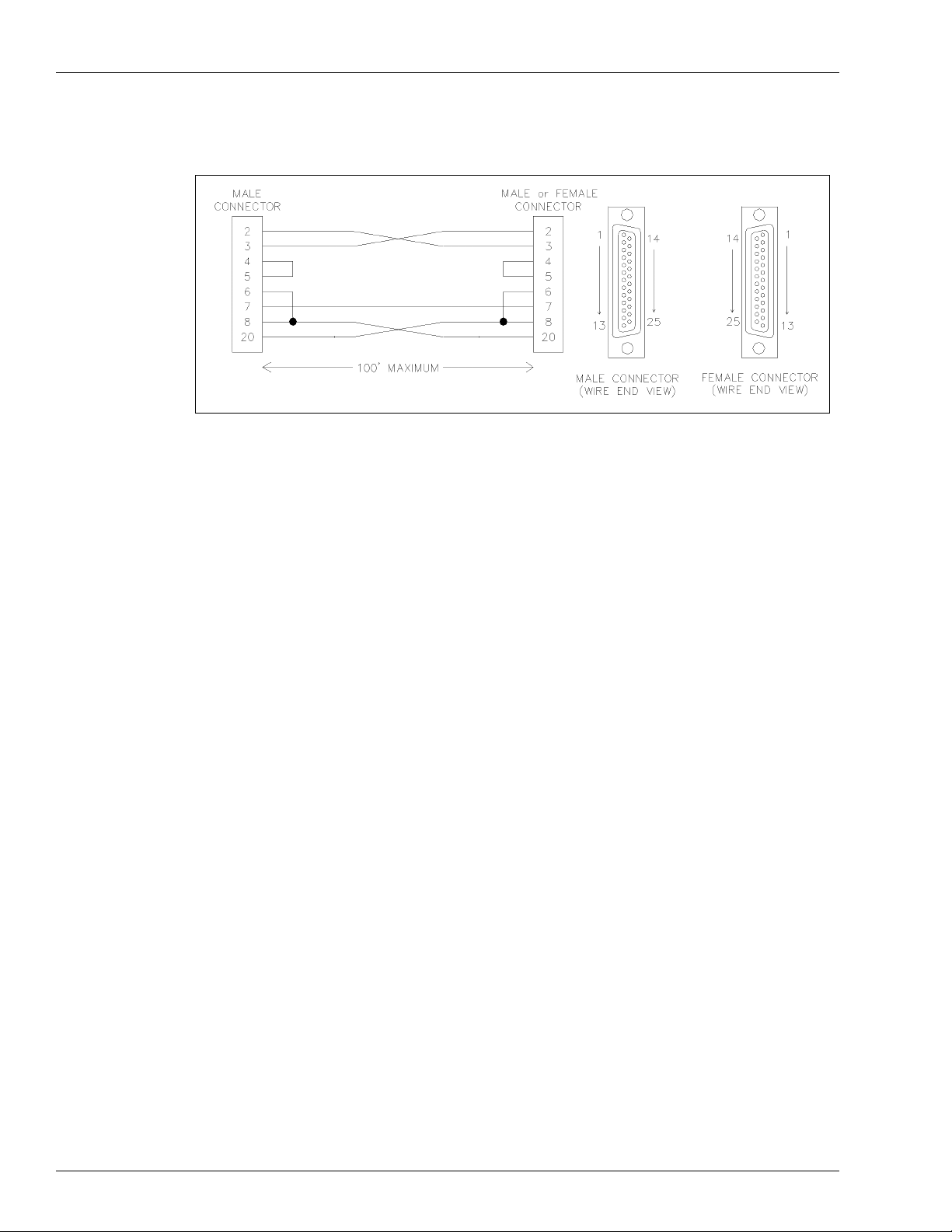
Figure 4-2: DTE Cross Cable (Part Number C05039: 8 feet M/M, Part Number C05928:
8 feet M/F)
RS-232 - Te rmination Box
A termination box can be purchased from Gasboy. Gasboy provides the installer with an easyto-wire terminal block connected to the proper pins on an RS-232D female connector. The
terminal block will accept up to 18 AWG wire.
RS-422 - SHMs
A Gasboy SHM and the appropriate interconnect cable must be used when the RS-422
communication mode is being used to communicate to the ports of the TopKAT system. It
must be used for distances between 100 and 1500 feet (31 and 455 meters). It can be used for
distances under 100 feet in place of RS-232 wiring. One SHM is required at the remote end of
the communication wiring. Refer to
diagrams.
“Port Communication Wiring” on page 28 for wiring
Page 22 MDE-4319E TopKAT™ Fuel Management System Installation Manual · August 2008
Page 29

Communication Requirements General Installation
Installation Requirements
• Internationally and domestically: All wiring is to be installed and used in accordance
with all applicable national, state and local building/fire/electrical codes. Additionally, in
the USA, installations must comply with the National Electrical Code (NFPA 70), NFPA
30, and the Automotive and Marine Service Station Code (NFPA 30A) codes and
regulations. Canadian installations must comply with the Canadian Electrical Code.
• Power: The AC power for the SHM must come from the same breaker that supplies the
peripheral device or the system (micro feed).
• Cable: A twisted-pair shielded cable is highly recommended for RS-422 wiring. Although
it is recommended that wires be run in a conduit away from AC wires, they can be
combined in the same conduit with AC wires, provided a UL-listed cable with the
following specifications is used:
- Conductor: 18 AWG stranded wire; two twisted-pairs
- Shield: Foil-wrapped 100% coverage and/or tinned copper braid 90% coverage
- Drain Wire: Stranded, tinned copper, 20 AWG or larger/or braided shield
- Voltage Rating: Maximum operating voltage of 600 V
- Environmental: Gas and oil-resistant; suitable for wet or dry locations
Gasboy can supply Belden 1063A (Part Number C09655) which is a UL-listed, 4conductor cable that meets the requirements listed above.
Note:Belden 1063A is UL-listed but not CSA-listed.
Cable with a voltage rating of less than 600 V must be installed in a separate conduit away
from all AC wires.
These modems must be connected with priv ate lines and will not work if connected into a
telephone network.
• Conduit: When you use the recommended shielded twisted-pair cable described
previously, RS-422 wires can be run with AC wires in a metal conduit. The shield drain
wire must be connected to the system AC ground. Only AC wires for the system and
pumps can be installed in the AC conduit. Do not run the cable outdoors without the use of
metal conduit. Do not run this cable overhead when outdoors.
• The cable can be run indoors without the use of a metal conduit. The shield drain wire
must be connected to the system AC ground (at one end only).
• If you use a cable other than what was recommended previously, the RS-422 field wires
must be installed in a metal conduit away from any AC wires.
• Distance: The maximum field wiring cable length must not exceed 1500 feet (455 m).
MDE-4319E TopKAT™ Fuel Management System Installation Manual · August 2008 Page 23
Page 30
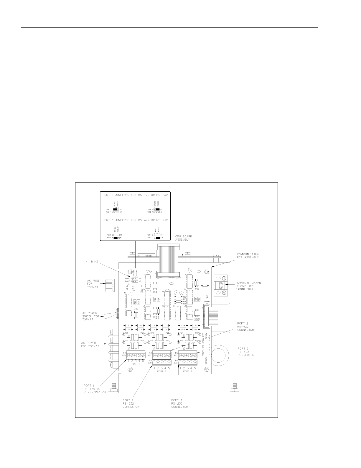
General Installation Terminal Block ID
Terminal Block ID
All communication wiring to the TopKAT system is terminated to green wiring connectors on
the communication board or the electronic housing assembly.
To gain access to the inside of the TopKAT system, proceed as follows:
1 Unlock the rear door and open it completely.
2 Unscrew the two captive screws, while holding the hood in place.
3 Slide the hood towards the rear of the unit (about 1 inch) and lift it straight up.
The left side of the electronic housing assembly is shown in Figure 4-3.
Figure 4-3: Electronic Housing Assembly - Left Side
Page 24 MDE-4319E TopKAT™ Fuel Management System Installation Manual · August 2008
Page 31

Description Series 9820 ASTRA Installation
5 – Series 9820 ASTRA Installation
Description
The Gasboy TopKAT system mounted on top of the ASTRA pedestal controls the dispenser
activation. The TopKAT system communicates with the ASTRA through the first of its three
asynchronous ports. Port 1 is a dedicated RS-485 communication loop that allows the
TopKAT system to control all functions of the ASTRA. Ports 2 and 3 can be set for either
RS-232 or RS-422 communications to a data terminal or computer. Refer to “Communication
Requirements” on page 19 for wiring considerations.
Figure 5-1: ASTRA Dimensions
MDE-4319E TopKAT™ Fuel Management System Installation Manual · August 2008 Page 25
Page 32

Series 9820 ASTRA Installation Description
Figure 5-2: 011889 Base Layout (Optional Post with TopKAT) - Models 9822 and 9823
Page 26 MDE-4319E TopKAT™ Fuel Management System Installation Manual · August 2008
Page 33

ASTRA to TopKAT Cabling Series 9820 ASTRA Installation
ASTRA to TopKAT Cabling
The interconnection of the ASTRA to the TopKAT system requires two cables:
• RS-485 communication cable
• AC power cable
Both the cables are supplied by Gasboy.
Figure 5-3: RS-485 Communication Cable
Figure 5-4: ASTRA to TopKAT AC Power Cable
For ASTRA switch settings, access, and location, refer to “Appendix B: Atlas CPU Board
Jumper Settings” on page B-1 and MDE-4652 Atlas™ 9800 Electronics Field Installation
Instructions.
MDE-4319E TopKAT™ Fuel Management System Installation Manual · August 2008 Page 27
Page 34

Series 9820 ASTRA Installation Port Communication Wiring
Port Communication Wiring
The following illustrations show the pin-to-pin layout of the possible wiring schemes for the
TopKAT ports. Each port may be wired for any of the wiring schemes, provided the
installation requirements are met as outlined in
Figure 5-5: RS-232 - D Connector
“Communication Requirements” on page 19.
Note: In the TopKAT system, the green connector must be connected to P4 on the
communication board for Port 2 , and P6 fo r P ort 3. The K1 a nd K2 jump er for the p ort
being used should be set to RS-232. Refer to
location of K1 and K2 jumpers.
“Terminal Block ID” on page 24 for the
Page 28 MDE-4319E TopKAT™ Fuel Management System Installation Manual · August 2008
Page 35
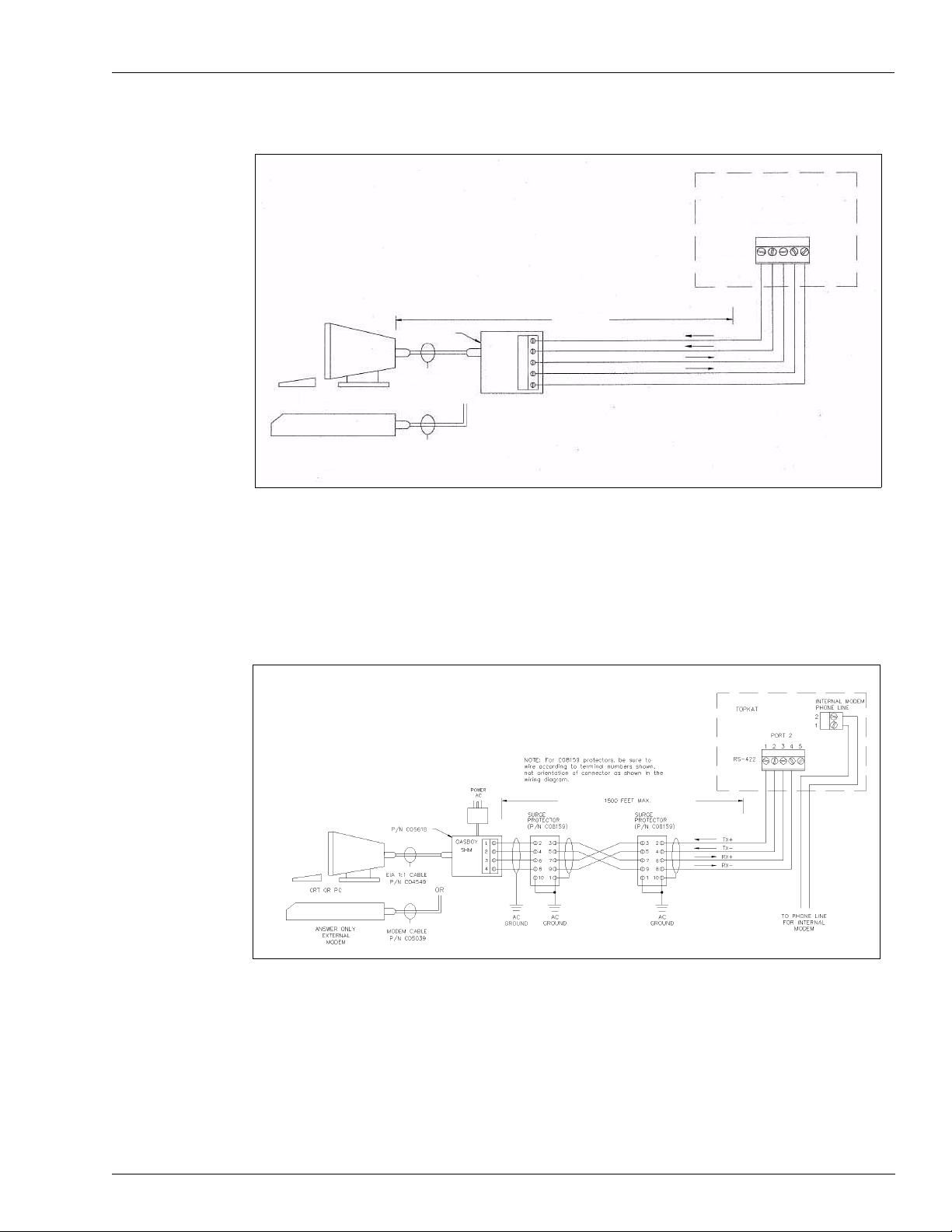
Port Communication Wiring Series 9820 ASTRA Installation
Figure 5-6: RS-232 - Gasboy Termination Box
Top KA T
PORT 2 OR 3
123 4 5
RS-232
100 FEET MAX
1
12
3
4
5
TXD
DTR
RXD
CD
GND
CRT OR PC
ANSWER ONLY
EXTERNAL MODEM
P/N C05769
EIA 1:1 CABLE
P/N C04549
MODEM CABLE
P/N C05039
GASBOY
RS-232
Note: In the TopKAT system, the green connector must be connected to P4 on the
communication board for Port 2 , and P 6 for P ort 3. The K1 and K2 jumper for the port
being used should be set to RS-232. Refer to
“Terminal Block ID” on page 24 for the
location of K1 and K2 jumpers.
Figure 5-7: RS-422 - Gasboy Short Haul Modem
Notes:1) In the TopKAT system, the green connector must be connected to P3 on the
communication board for Port 2 and P5 for Port 3.
2) If a TopKAT internal modem is used, Port 3 is not available for external
communication wiring.
3) The K1 and K2 jumper for the port being used should be set to RS-422. Refer to
“Terminal Block ID” on page 24 for the location of K1 and K2 jumpers.
MDE-4319E TopKAT™ Fuel Management System Installation Manual · August 2008 Page 29
Page 36

Series 9820 ASTRA Installation TopKAT Master/Satellite Communications Wiring
Figure 5-8: Internal Modem
Notes:1) If a TopKAT internal modem is used, Port 3 is not available for external
communication wiring.
2) The K2 jumper for Port 3 should be removed. Refer to “Terminal Block ID” on
page 24 for the location of the K2 Jumper.
TopKAT Master/Satellite Communications Wiring
Figure 5-9: Two TopKATs, Three ASTRA Pumps, with Short Haul Modem Wiring
Page 30 MDE-4319E TopKAT™ Fuel Management System Installation Manual · August 2008
Page 37

Wiring for a CRT Terminal and Okidata Printer Series 9820 ASTRA Installation
Wiring for a CRT Terminal and Okidata Printer
Figure 5-10 shows the connections between the TopKAT port and the CRT terminal and
Okidata® printer.
Figure 5-10: TopKAT Port to CRT to Okidat a Printer Connections
CRT Terminal (M07339B001)
and Keyboard (Q13181-02)
Okidata ML 186 Printer with
Super-speed Serial I/F (Part
Number PA03730000)
*Part Number C03813 is the
combination of M07339B001,
Q13181-02 and C01633
Wiring for Modems
External Modems
The type of phone line required for communication via an external modem is dependent on the
type of modem used and the method of communication desired. Consult the manual that
comes with the modem for specific requirements.
Internal Modem
When the To pKAT internal modem is installed, Port 3 communication is routed through the
modem in place of being wired at the DC Junction box. Jumper K2 should be removed. Refer
to
“Terminal Block ID” on page 24 for the location of the K1 and K2 jumpers. The phone line
for the internal modem can be installed in the DC conduit. If you install the modem in the DC
conduit, a two twisted-pair shielded cable must be used as specified in
Requirements” on page 19 and the shield drain wire must be connected to the system AC
ground. Check with your local phone company for proper installation of the phone line.
“Communication
MDE-4319E TopKAT™ Fuel Management System Installation Manual · August 2008 Page 31
Page 38

Series 9820 ASTRA Installation Wiring for Modems
This page is intentionally left blank.
Page 32 MDE-4319E TopKAT™ Fuel Management System Installation Manual · August 2008
Page 39

Description TopKAT Master/Satellite
6 – TopKAT Master/Satellite
Description
The TopKAT master/satellite option allows up to eight TopKAT units to be linked together
through a full-duplex RS-485 data loop, with one acting as the master controlling unit. The
master is the only unit that will need to have a data communication link as it will collect all
transactions and maintain the complete database for the entire site. The data communication
ports of the satellite units are disabled. The individual TopKAT units may use the standard
RS-485 loop (9800 pumps) to communicate to their pumps or the mechanical interface. The
interface must be the same for each pump within an individual TopKAT system. However,
both types of pump interfaces may be combined within a master/satellite configuration.
Note: Full-duplex communication requires four wires and is not presently supported in the
9850, as it does not have the necessary communication wires.
There are four possible configurations for the master/satellite:
• All electronic, where the TopKAT system can control up to eight electronic 9800/
ASTRAs and up to seven satellite readers
• All mechanical, where the master TopKAT system controls up to two mechanical hoses
and up to 14 other hoses (two hoses each for up to seven TopKATs)
• Combination, where the master TopKAT system controls two electronic 9800/ASTRAs
and up to 14 mechanical hoses (two hoses each for up to seven TopKATs)
• Mechanical pumps, where the master TopKAT system can control up to eight mechanical
pumps (four hoses per Mechanical PCU, up to two Mechanical PCUs) and up to seven
satellite readers.
MDE-4319E TopKAT™ Fuel Management System Installation Manual · August 2008 Page 33
Page 40

Figure 6-1: Wiring Diagram: TopKAT Master/Satellite Communications Wiring - 9820
Description
Page 34 MDE-4319E TopKAT™ Fuel Management System Installation Manual · August 2008
Page 41

Figure 6-2: Wiring Diagram: TopKAT Master/Satellite Communications Wiring - 9800
YELLOW
GRAY
VIOLET
BLUE
Description
BLACK
WHITE
MDE-4319E TopKAT™ Fuel Management System Installation Manual · August 2008 Page 35
Page 42

TopKAT Master/Satellite Description
Figure 6-3: Wiring Diagram: RS-422 - Gasboy Short Haul Modem - Master/Satellite
Modem
TWO SPARE WIRES FOR
OTHER OPTIONS “Q” AND “K”
MODELS ONLY
1
Page 36 MDE-4319E TopKAT™ Fuel Management System Installation Manual · August 2008
Page 43

Description TopKAT Master/Satellite
Figure 6-4: Wiring Diagram: Internal Modem with Master/Satellite Option
1
Notes:1) In the TopKAT system, Port 3 is not available for external communication wiring
when an internal modem is used. For Port 2, refer to the Master/Satellite Wiring
drawings (
Figure 6-1 on page 34, Figure 6-2 on page 35, or Figure 6-3 on page 36).
2) The K2 jumper for Port 3 should be r emoved when you use an internal modem. Refer
“Terminal Block ID” on page 24 for the location of K1 and K2 jumpers.
to
MDE-4319E TopKAT™ Fuel Management System Installation Manual · August 2008 Page 37
Page 44

TopKAT Master/Satellite Wiring for Modems
Figure 6-5: Wiring Diagram: CRT Terminal and Okidata Printe r
CRT Terminal (M07339B001)
and Keyboard (Q13181-02)
Okidata ML 186 Printer with
Super-speed Serial I/F (Part
Number PA03730000)
*Part Number C03813 is the
combination of M07339B001,
Q13181-02 and C01633
Wiring for Modems
External Modems
The type of phone line required for communication via an external modem is dependant on the
type of modem used and the method of communication desired. Refer to the manual that is
provided with the modem for specific requirements.
Internal Modems
When the TopKAT internal modem is installed, Port 3 communication is routed through the
modem in place of being wired at the DC Junction box. Jumper K2 should be removed. Refer
to
“Terminal Block ID” on page 24 for the location of K1 and K2 jumpers. The phone line for
the internal modem can be installed in the DC conduit. If you install the modem in the DC
conduit, a two twisted-pair shielded cable must be used as specified in
Requirements” on page 19 and the shield drain wire must be connected to the system AC
ground. Check with your local phone company for proper installation of the phone line.
“Communication
Page 38 MDE-4319E TopKAT™ Fuel Management System Installation Manual · August 2008
Page 45

Description Mechanical Interface Option
7 – Mechanical Interface Option
Description
The Mechanical Interface option for the TopKAT system allows the unit to control fueling and
gather information from up to two mechanical hose outlets (two singles or one twin). The
TopKAT system with mechanical interface is mounted on top of a 50 inch high pedes ta l . All
mechanical interface components are mounted within the head of the TopKAT system and all
wiring connections are made within the TopKAT system. Electronics or control devices are
not present in the pedestal. The TopKAT system with mechanical interface can also be used in
a master/satellite configuration.
The mechanical interface includes two solid-state relays and one manual override switch for
each hose outlet, which control power to the fuel dispensing equipment (for the override
switches to place the pump in MANUAL position, power must be supplied to the TopKAT
system). The TopKAT system can handle quantity pulsing rates of 1, 10, 100, 500, and 1000
per gallon measurement and 1, 10, 100 and 250 per liter measurement.
MDE-4319E TopKAT™ Fuel Management System Installation Manual · August 2008 Page 39
Page 46

Mechanical Interface Option Dimensions
Dimensions
Figure 7-1: TopKAT Dimensions (with Pedestal)
Page 40 MDE-4319E TopKAT™ Fuel Management System Installation Manual · August 2008
Page 47

Conduit Layout Mechanical Interface Option
Conduit Layout
Refer to “General Installation” on page 11 for conduit, power requirements, and wire size
considerations.
Figure 7-2: TopKAT Conduit Layout
MDE-4319E TopKAT™ Fuel Management System Installation Manual · August 2008 Page 41
Page 48

Mechanical Interface Option Terminal Block ID
Terminal Block ID
Figure 7-3 shows the mechanical interface components. Refer to “Terminal Block ID” on
page 24 for the TopKAT Comm Assembly.
To gain access to the inside of the TopKAT system, proceed as follows:
1 Unlock the rear door and open it completely.
2 Unscrew the two captive screws holding the hood in place.
3 Slide the hood towards the rear of the unit (about 1”) and lift it straight up.
The view in Figure 7-3 is from the rear of the electronic housing assembly.
Figure 7-3: Mechanical Interface Components
Page 42 MDE-4319E TopKAT™ Fuel Management System Installation Manual · August 2008
Page 49

System Pump and Dispenser Wiring Mechanical Interface Option
System Pump and Dispenser Wiring
Wiring Precautions
!
WARNING
To reduce the risk of electrical shock when servicing, turn off all power to the pump/dispenser.
In submersible pump applications, turn off all power to the submersible pump and any other
dispensers which use that submersible pump. AC power can feed back into a shutoff dispenser
when dispensers share a common submersible pump or starter relay.
!
AVERTISSEMENT
Pour réduire le risque de choc électrique lors de l'entretien/révision, coupez totalement le
courant à la pompe/distributeur. Dans les applications de pompe immersible, coupez
totalement le courant à la pompe immersible et tous autres distributeurs qui utilisent la pompe
immersible. Le courant alternatif peut alimenter de nouveau un distributeur à l'arrêt quand les
distributeurs partagent une pompe immersible commune ou un relais de démarrage.
The quality of the electrical installation is a major factor in maintaining proper safety levels
and providing trouble-free operation of your Gasboy pump/dispenser. To ensure a quality
installation, follow these rules:
• All wiring must be installed and used in accordance with local building/fire codes, all
Federal, State, and Local codes, the National Electrical Code (NFPA 70), NFPA 30, and
the Automotive and Marine Service Station Code (NFPA 30A) codes and regulations.
Canadian users must also comply with the Canadian Electrical Code.
• Use approved conduit and insulated gasoline and oil resistant copper wiring of the proper
size.
• Wire connections must be tightly spliced and secured with a wire nut; close off the open
end of the wire nut with electrical tape.
• Install an emergency power cutoff. In addition to circuit breaker requirements of NFPA
70, NFPA 30, NFPA 30A and the Canadian Electrical Code (Canadian users only), a
single control that simultaneously removes AC power from all site dispensing equipment
is recommended. This control must be readily accessible, clearly labeled, and in
accordance with local codes.
In order to provide the highest level of safety to you, your employees, and customers, all
employees must be trained as to the location of the power supply and the procedure for turning
off power to the entire system.
MDE-4319E TopKAT™ Fuel Management System Installation Manual · August 2008 Page 43
Page 50

Mechanical Interface Option Control Lines for Mechanical Pumps/Dispensers
Control Lines for Mechanical Pumps/Dispensers
Descriptions of the control lines are provided to familiarize the installer with the control inputs
and outputs that are used to control a mechanical pump/dispenser. Reading these descriptions
will give the installer a better working knowledge of the system and aid in planning the site
wiring.
Grounding
T o ensure proper operation of the equipment and provide the necessary safety factors, this unit
must be grounded. A ground wire (preferably green) must be connected between the ground
wire of the system and the main electrical service panel. One (1) earth ground connection is
required per unit. A ground rod must be installed at the main electrical panel in accordance
with the National Electrical Code. This ground rod must be a solid, corrosion-resistant
conductor. It should be properly tied into the ground bus strip of the panel. The neutral and
ground bus strips must be bonded together (unless prohibited by local codes).
Reset Motor Feed
This is a 115 VAC input which is supplied through the pump handle switch to activate the
reset motor. This line should be switched through the TopKAT system and should only be on
when the pump/dispenser is authorized or in Manual mode. Without power supplied to this
line, the pump/dispenser will not reset when the pump handle is turned on. Two feed lines are
provided for twins. This feed is also connected to the input of one of the internal switches of
the electric reset. When the reset finishes its cycle, the 115 VAC input to the switch will be
passed through as an output, causing the solenoid valve (optional in some models) to open,
and the Reset Complete line to indicate 115 VAC.
Pump Motor Feed
This is a 115 VAC input which is supplied to the input side of one of the internal switches of
the electric reset. This line should be switched through the TopKAT system and should only
be on when the pump/dispenser is authorized or in Manual mode. When the reset finishes its
cycle, the 115 VAC input to the switch is passed through as an output causing the pump motor
to receive power and begin fueling. Without power to this line, the unit would reset, but be
unable to fuel. Two feed lines are provided in twins which contain two motors. The gauge of
this wire (and its neutral wire) must be determined according to the size of the motor, the
voltage at which the motor will be powered (115 VAC or 230 VAC), and the distance from the
breaker panel to the pump. It is possible to combine the pump motor feeds for twins and
supply them from one breaker. However, the gauge of the wire needs to be adjusted to handle
the load of two motors.
Note: 230 VAC is developed across a motor when the other leg of the motor is connected to a
Neutral Feed
This is the AC current return line to the breaker panel for all attached devices (pump motor,
reset motor, solenoid valves). The gauge of this wire must be equal to that of the pump motor
feed (suction pumps) or submersible feed (dispensers).
Phase 2 Feed.
Page 44 MDE-4319E TopKAT™ Fuel Management System Installation Manual · August 2008
Page 51

Control Lines for Mechanical Pumps/Dispensers Mechanical Interface Option
Submersible Feed, Submersible Drive
This is a 115 VAC input which is supplied to the input side of one of the internal switches of
the electric reset. This line must be switched through the TopKAT system and only be on
when the pump/dispenser is authorized or in Manual mode. When the reset finishes its cycle,
the 115 VAC input to the switch is passed through as an output (submersible drive) to drive a
starter relay or to directly drive a submersible motor up to 3/4 HP at 115 VAC or 1-1/2 HP at
230 VAC. Any submersible motor exceeding this limitation must use a starter relay.
Note: 230 VAC is developed across a motor when the other leg of the motor is connected to a
Phase 2 Feed.
Reset Complete (Switch Detect)
This is a 115 VAC output which is used to indicate the reset is complete and the pump/
dispenser is ready to dispense the product. Two lines are provided for twins. This line must
only be used when monitoring of the pump/dispenser is desired (for example, when used with
a fuel management system). This line must be capped when not in use.
Light Feed
This is a 115 VAC input required to power optional fluorescent lights that may be available in
a pump/dispenser. In a site configuration using multiple dispensers (or pumps), the power for
the lights of up to eight units can be supplied by one breaker. The light feed is not controlled
by the TopKAT system.
Light Neutral
This is a return line for AC current from the lights to the breaker panel.
Phase 2 Feed
This is a hot feed which is the opposite phase of the pump motor feed. This line and the pump
motor feed are used for 230 VAC motor applications.
Pulser - Mechanical Pump
This supplies a DC output which is provided to indicate the quantity dispensed.
MDE-4319E TopKAT™ Fuel Management System Installation Manual · August 2008 Page 45
Page 52

Mechanical Interface Option Control Lines for Gasboy 9800 or 9820 Electronic Pumps/Dispensers
Control Lines for Gasboy 9800 or 9820 Electronic Pumps/ Dispensers
Note: This section pertains to 9800 electronic pumps/dispensers running as mechanical units
(standalone operation). This scenario would only be used when controlling two pumps:
one mechanical and one electronic running as mechanical, from a single TopKAT
system.
Descriptions of the control lines are provided to familiarize the installer with the control inputs
and outputs that are used to control the Series 9800 and 9820 dispensing units. Reading these
descriptions will give the installer a better working knowledge of the system and aid in
planning the site wiring.
The Series 9800 may be provided for use with 230 VAC power for international applications.
The operating voltage for control lines to these units is shown in parentheses as (230 VAC
International).
Ground
To ensure proper operation of the equipment and provide the necessary safety factors, a good
ground line must be provided. A ground wire (preferably green) must be connected between
the ground wire of the system and the main electrical service panel. One (1) earth ground
connection is required per unit. The ground rod is to be a solid, corrosion-resistant conductor
and must be installed at the main electrical panel in accordance with the National Electrical
Code. It should be properly tied into the ground bus strip of the panel. The neutral and ground
bus strips must be bonded together (unless prohibited by local codes).
Micro Feed
Micro Neutral
The Micro Feed is a 115 VAC (230 VAC International) input required to power the
microprocessor of the register's electronics. This power must always remain on and must be on
a separate breaker from the control lines (Control/Pump Motor Feed or Control/Subm Feed Side 1, Side 2). This must also be on a separate breaker from the fluorescent lights to reduce
electrical noise and allow for separate control of the lights. In a site configuration using
multiple dispensing units, the power for the microprocessors of up to 8 units can be supplied
by one breaker.
The Micro Neutral is a return line for AC current from the microprocessor of the dispensing
unit to the breaker panel.
Page 46 MDE-4319E TopKAT™ Fuel Management System Installation Manual · August 2008
Page 53

Control Lines for Gasboy 9800 or 9820 Electronic Pumps/Dispensers Mechanical Interface Option
Control/Pump Motor Feed
The Control/Pump Motor Feed is a 115 VAC (230 VAC International) input which is required
to power and authorize the control line. This line is used to provide authorization for the
dispensing unit (when enabled through the DIP switches). A resistor assembly must be
installed between the Control Feed line and Feed Neutral to prevent false triggering of the
authorization input. The resistor assembly is 8.2 kilo-ohm, 10 Watt (part number C05818) for
115/230 VAC domestic and 30 kilo-ohm, 10 Watt (part number C06683) for 230 VAC
International wiring. Two Control/Pump Motor Feed lines are provided for twins.
The Control/Pump Motor Feed line is used to power the slow flow and fast flow valves (when
installed). The power used to control the pump is also provided by this line. It is possible to
combine the control lines for twins and supply them from one breaker. However, the gauge of
the wire needs to be adjusted to handle the load of two motors. The Reset Complete signal
used for external monitoring of the pump also originates from the Control/Pump Motor Feed
line.
External Valve
The External Valve line is used to directly power an anti-siphon valve mounted on top of an
aboveground tank. The valve must operate at the same voltage as the pump motor and the
current draw must not exceed 1 A, or the valve must be switched through an external relay
controlled by the External Valve line. Do not connect two or more External Valve lines
together. If more than one pump is drawing from the tank, separate anti-siphon valves must be
installed, or each External Valve line must operate an external relay which then operates the
valve.
Neutral Feed
The Neutral Feed is the AC current return line to the breaker panel for all attached devices
(pump motor, solenoid valves).
Control/Submersible Feed (Control/Subm Feed)
The Control/Subm Feed is a 115 VAC (230 VAC International) input which is required to
power and authorize the control line. This line is used to provide authorization for the
dispensing unit (when enabled through the DIP switches). A resistor assembly must be
installed between the Control Feed line and Feed Neutral to prevent false triggering of the
authorization input. The resistor assembly is 8.2 kilo-ohm, 10 Watt (part number C05818) for
115/230 VAC domestic and 30 kilo-ohm, 10 Watt (part number C06683) for 230 VAC
International wiring. This line also supplies the power which is switched to the slow flow and
fast flow valves along with the Reset Complete signal. Two lines are provided for twins.
Units with Standard Submersible Drive (Subm Drive)
Power for the Subm Drive line originates from this input. The submersible starter relay line, in
standard dispensers, is not capable of directly powering a submersible pump. A starter relay
must be used. The control lines for twin dispensers can be combined together and powered by
one breaker if individual control of each side is not desired. In a site configuration using
multiple dispensers, the power for the control lines of up to eight hose outlets (eight singles or
four twins) can be supplied from one breaker.
MDE-4319E TopKAT™ Fuel Management System Installation Manual · August 2008 Page 47
Page 54

Mechanical Interface Option Control Lines for Gasboy 9800 or 9820 Electronic Pumps/Dispensers
Units with Optional Direct Submersible Drive
Power for the Subm Drive line originates from this input. 9800 Series dispensing units
equipped with the optional relays for direct submersible pump drive can be connected directly
to submersible pumps up to 3/4 HP at 115 VAC or 1-1/2 HP at 230 VAC. The gauge of this
wire should be determined according to the size of the motor, the voltage at which the motor
will be powered, and the distance from the breaker panel to the pump.
Submersible Starter Drive (Subm Starter Drive)
The Subm Starter Drive is a 115 VAC (230 VAC International) output used to control a
submersible starter relay. Two lines are provided for twins. This line is capable of supplying
300 mA of AC current to control the coil of the submersible motor contactor (starter relay).
This is sufficient for directly connecting to the popular models. However, refer to the
contactor (relay) manufacturer's data sheet for the sealed VA rating. Divide the sealed VA by
the coil voltage to determine the current. This line must not be connected directly to the
submersible pump, shorted to any conduit or chassis metal, or wired incorrectly, or the CPU
PC board will be instantly damaged. This line must be capped when not in use.
Submersible Drive (Subm Drive)
This line is always present for dispensers, but is active only when Subm Drive relays are
supplied. The Subm Drive is a 115/230 VAC (230 VAC International) output used to control
the submersible starter relay or submersible pump. When connected directly to the
submersible pump, the motor size cannot exceed 3/4 HP at 115 VAC or 1-1/2 HP at 230 VAC.
Two lines are provided for twins. In cases where both lines are controlling the same starter
relay or pump, they can be combined.
Reset Complete (Switch Detect)/Slow Flow
The Reset Complete/Slow Flow is a 115 VAC (230 VAC International) output which is used
to indicate that the reset process is complete and the unit is ready to dispense the product. It is
required when used with a TopKAT fuel management system. It may also be used to control a
remote (satellite) slow flow valve. Two lines are provided for twins.
Phase 2 Feed
The phase 2 feed is a hot feed which is the opposite phase of the pump motor feed. This line
and the pump motor feed are used for 230 VAC motor applications. The Phase 2 Feed must be
switched through a separate relay to prevent false triggering of the authorization signal.
Light Feed
The Light Feed is a 115 VAC input required to power the fluorescent lights. In a site
configuration using multiple dispensers (or pumps), the power for the lights of up to 8 units
can be supplied by one breaker. This must be on a separate breaker from the Micro/Heater
Feed to reduce electrical noise and allow for separate control of the lights.
Page 48 MDE-4319E TopKAT™ Fuel Management System Installation Manual · August 2008
Page 55

Control Lines for Gasboy 9800 or 9820 Electronic Pumps/Dispensers Mechanical Interface Option
Light Neutral
The Light Neutral is a return line for AC current from the lights to the breaker panel. When a
separate breaker is not used to control the lights, the light neutral is attached to the Micro
Neutral.
Pulser - 9800/9820
CAUTION
The TopKAT Pump Control Printed Circuit Board (PCB) must be set for electronic pulser (100:1
or higher) as shown in “Terminal Block ID” on page 42. Failure to set the Pump Control PCB
jumpers properly will damage the TopKAT.
When a 9800 Series dispensing unit is wired to the TopKAT using the mechanical interface,
the dispensing unit must include the optional pulser interface PCB (C06425, M05158A001,
M05158A002, and M06587A001) to provide a pulse output. This pu lser output pr ovides a DC
output to indicate the quantity dispensed. This is an open collector output. This output can sink
up to 100 milliamps DC at voltages up to 24 VDC. The output pulse rate can be configured by
a DIP switch on the 9800 CPU PCB for rates of 1, 10, 100, 250, or 500 pulses p e r gallo n or 1,
10, or 100 pulses per liter. For the 9850 pump, the pulse rates are 1, 10, or 100 pulses per
gallon or 1 or 10 pulses per liter. For 9840K (liters), the pulse rate is 10 pulses per liter. An
additional output is provided for a twin. A DC ground line from the TopKAT must be
connected to the DC ground line provided from the electronic register.
MDE-4319E TopKAT™ Fuel Management System Installation Manual · August 2008 Page 49
Page 56

Mechanical Interface Option Wiring Diagrams
Wiring Diagrams
Figure 7-4: Wiring Diagram: Veeder-Root® Reed Switch Pulser, 1871 Series 10:1
Figure 7-5: Wiring Diagram: Veeder-Root Electronic Pulser, 7671 Series 100:1
Pulser Wiring Notes
Notes:1) All the pulsers shown above are connected to Hose 1.
2) Jumpers on the Pump Control PCB must be properly jumpered according to the
pulser type. This must be done by the person performing the start-up . Power to the
system must not be turned on prior to this setup.
3) Refer to “Conduit Layout” on page 41 for detailed system installation specifications.
Page 50 MDE-4319E TopKAT™ Fuel Management System Installation Manual · August 2008
Page 57
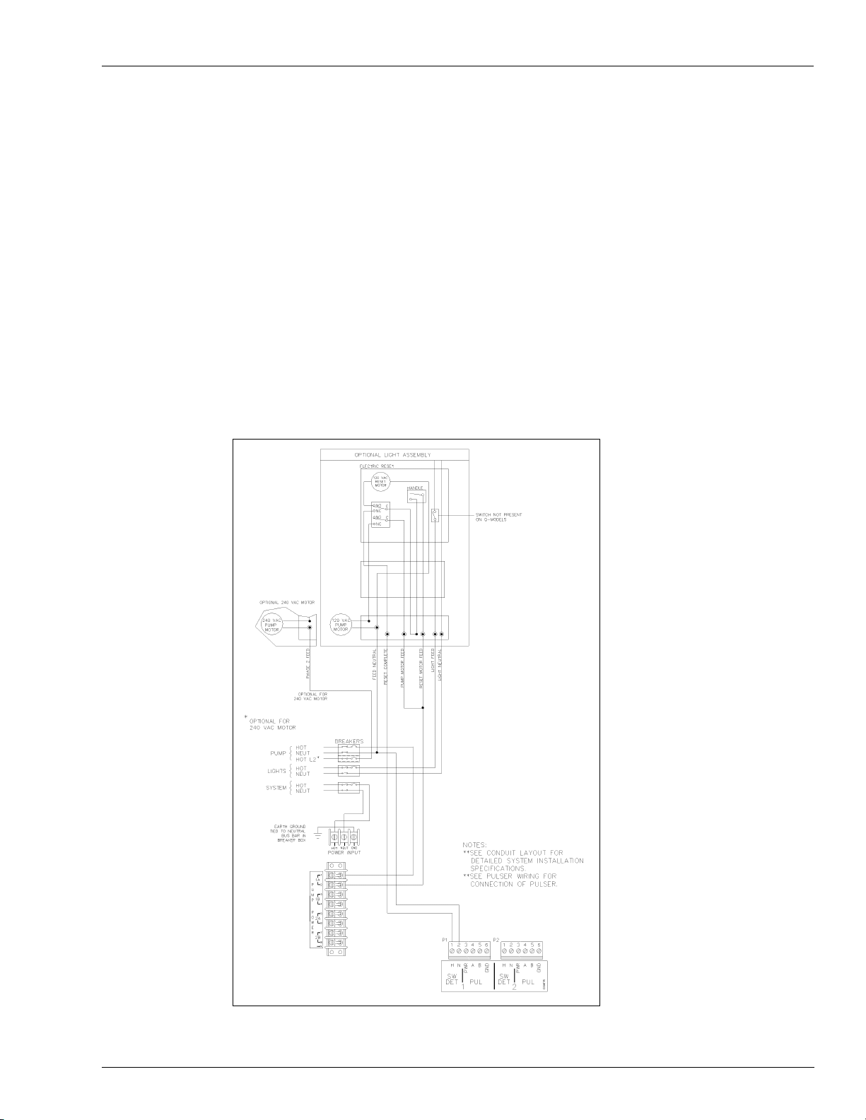
Wiring Diagrams Mechanical Interface Option
4) When installed in a separate DC conduit, 18 AWG wires are required for
installation. Although it is recommended that DC pulser wires be run in a separate
conduit away from AC wires, they can be combined in the same conduit with AC
wires if UL-listed cable with the following specifications is used:
• Conductor: 18 AWG stranded wire. Number of conductors to be determined by the
pulser
• Shield: Foil-wrapped 100% coverage and/or tinned copper braid 90% coverage
• Drain Wire: Stranded, tinned copper, 20 AWG or larger/or braided shield
• Voltage Rating: Maximum operating voltage of 600 VDC
• Environmental: Gas and oil-resistant; suitable for wet or dry locations.
Gasboy can supply Belden 1063A (part number C09655) which is a UL-listed, 4-conductor
cable that meets the requirements listed above.
Note: Belden 1063A is UL-listed but not CSA-listed.
Figure 7-6: Wiring Diagram: Single Suction Pump, 115 VAC/230 VAC, Veeder-Root
Reset
MDE-4319E TopKAT™ Fuel Management System Installation Manual · August 2008 Page 51
Page 58
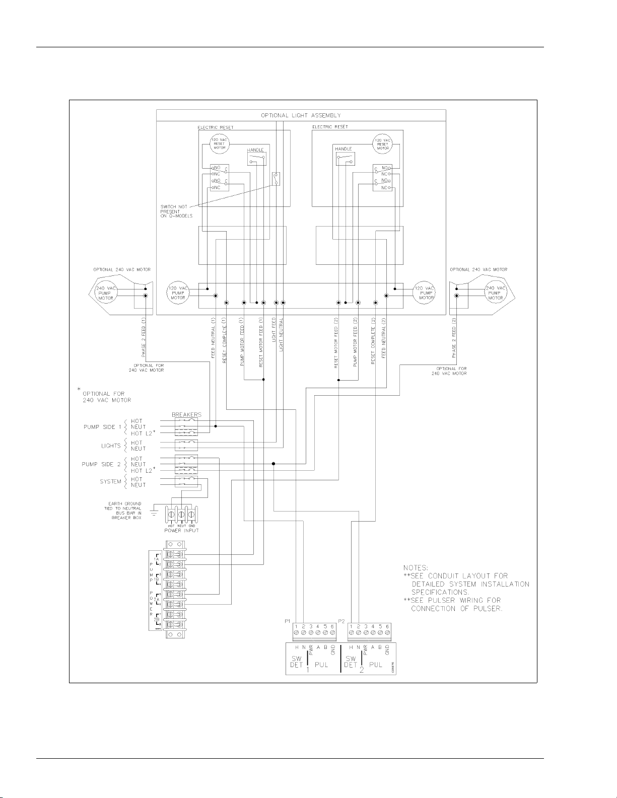
Mechanical Interface Option Wiring Diagrams
Figure 7-7: Twin Suction Pump, 115 VAC/230 VAC, Veeder-Root Reset
Page 52 MDE-4319E TopKAT™ Fuel Management System Installation Manual · August 2008
Page 59

Wiring Diagrams Mechanical Interface Option
Figure 7-8: Wiring Diagram: Twin Suction Pump, Single Motor, 115 VAC/230 VAC,
Veeder-Root Reset
MDE-4319E TopKAT™ Fuel Management System Installation Manual · August 2008 Page 53
Page 60

Mechanical Interface Option Wiring Diagrams
Figure 7-9: Wiring Diagram: Single Dispenser, Veeder-Root Reset
Page 54 MDE-4319E TopKAT™ Fuel Management System Installation Manual · August 2008
Page 61

Wiring Diagrams Mechanical Interface Option
Figure 7-10: Wiring Diagram: Twin Dispenser, Veeder-Root Reset
MDE-4319E TopKAT™ Fuel Management System Installation Manual · August 2008 Page 55
Page 62

Mechanical Interface Option Wiring Diagrams
Figure 7-11: Wiring Diagram: Single Suction Pump, 115 VAC/230 VAC, Gasboy Reset
Note: For units with two motors, the pump may have to be operated at 240 VAC to limit the
AC current required.
Page 56 MDE-4319E TopKAT™ Fuel Management System Installation Manual · August 2008
Page 63

Wiring Diagrams Mechanical Interface Option
Figure 7-12: Wiring Diagram: Twin Suction Pump, 115 VAC/230 VAC, Gasboy Reset
MDE-4319E TopKAT™ Fuel Management System Installation Manual · August 2008 Page 57
Page 64

Mechanical Interface Option Wiring Diagrams
Figure 7-13: Wiring Diagram: Twin Suction Pump, Single Motor, 115 VAC/230 VAC,
Gasboy Reset
Page 58 MDE-4319E TopKAT™ Fuel Management System Installation Manual · August 2008
Page 65

Wiring Diagrams Mechanical Interface Option
Figure 7-14: Wiring Diagram: Single Dispenser, Gasboy Reset
MDE-4319E TopKAT™ Fuel Management System Installation Manual · August 2008 Page 59
Page 66

Mechanical Interface Option Wiring Diagrams
Figure 7-15: Wiring Diagram: Twin Dispenser, Gasboy Reset
Page 60 MDE-4319E TopKAT™ Fuel Management System Installation Manual · August 2008
Page 67

Wiring Diagrams Mechanical Interface Option
Figure 7-16: Wiring Diagram: 9852, 9853 Pumps
Diagrams shown are for Q Model pumps. If your pump is an A model, DC Junction box will be separate.
Notes:
1. The power resistor assembly is 8.2 kilo-ohm, 10 W (part number C05818) for 115/230 V AC domestic unit s and 30 kilo-ohm,
10 W (part number C06683) for 230 VAC International units.
2. Before applying power, the TopKAT Pump Control PCB jumpers must be set for electronic pulser as shown in “Terminal
Block ID” on page 42. Failure to properly set the jumpers will damage the TopKAT.
3. The wire colors may vary. Refer to current pump wiring diagrams.
4. When used with an aboveground tank, the anti-siphon valve mounted on the tank must be driven from the External Valve
line, have the same operating voltage as the pump motor, and the current draw must not exceed 1 Amp. If these conditions
are not met, it must be controlled by an external relay driven from the External Valve line. DO NOT connect the anti-siphon
valve or external relay to the Reset Complete line. DO NOT connect two or more External Valve lines together. If more than
one pump is drawing from the tank, separate anti-siphon valves must be installed, or each External Valve line must operate
an external relay which then operates the valve.
MDE-4319E TopKAT™ Fuel Management System Installation Manual · August 2008 Page 61
Page 68

Mechanical Interface Option Wiring Diagrams
Figure 7-17: Wiring Diagram: 9852TW2, 9853TW2, 9853TW1M Pumps
Diagrams shown are for Q Model pumps. If your pump is an A model, DC Junction box will be separate.
Notes:
1. The power resistor assembly is 8.2 kilo-ohm, 10 W (part number C05818) for 115/230 VAC domestic units and 30 kiloohm, 10 W (part number C06683) for 230 VAC International units.
2. Before applying power, the TopKAT Pump Control PCB jumpers must be set for electronic pulser as shown in “Terminal
Block ID” on page 42. Failure to properly set the jumpers will damage the TopKAT.
3. The wire colors may vary. Refer to current pump wiring diagrams.
4. When used with an aboveground tank, the anti-siphon valve mounted on the tank must be driven from the External Valve
line, have the same operating voltage as the pump motor, and the current draw must not exceed 1 Amp. If these
conditions are not met, it must be controlled by an external relay driven from the External Valve line. DO NOT connect
the anti-siphon valve or external relay to the Reset Complete line. DO NOT connect two or more External Valve lines
together. If more than one pump is drawing from the tank, separate anti-siphon valves must be installed, or each
External Valve line must operate an external relay which then operates the valve.
Page 62 MDE-4319E TopKAT™ Fuel Management System Installation Manual · August 2008
Page 69

Wiring Diagrams Mechanical Interface Option
Figure 7-18: Wiring Diagram: 9853HC, 9840 Pumps
Diagrams shown are for Q Model pumps. If your pump is an A model, DC Junction box will be separate.
Notes:
1. The power resistor assembly is 8.2 kilo-ohm, 10 W (part number C05818) for 115/230 VAC domestic units and 30 kilo-ohm,
10 W (part number C06683) for 230 VAC International units.
2. Before applying power, the TopKAT Pump Control PCB jumpers must be set for electronic pulser as shown in “Terminal
Block ID” on page 42. Failure to properly set the jumpers will damage the TopKAT.
3. The wire colors may vary. Refer to current pump wiring diagrams.
MDE-4319E TopKAT™ Fuel Management System Installation Manual · August 2008 Page 63
Page 70

Mechanical Interface Option Wiring Diagrams
Figure 7-19: Wiring Diagram: 9852TW1 Pump
Diagrams shown are for Q Model pumps. If your pump is an A model, DC Junction box will be separate.
Notes:
1. The power resistor assembly is 8.2 kilo-ohm, 10 W (part number C05818) for 115/230 VAC domestic units and 30 kiloohm, 10 W (part number C06683) for 230 VAC International units. Two assemblies required for twins.
2. Before applying power, the TopKAT Pump Control PCB jumpers must be set for electronic pulser as shown in “Terminal
Block ID” on page 42. Failure to properly set the jumpers will damage the TopKAT.
3. The wire colors may vary. Refer to current pump wiring diagrams.
4. When used with an aboveground tank, the anti-siphon valve mounted on the tank must be driven from the External
Valve line, have the same operating voltage as the pump motor, and the current draw must not exceed 1 Amp. If these
conditions are not met, it must be controlled by an external relay driven from the External Valve line. DO NOT connect
the anti-siphon valve or external relay to the Reset Complete line. DO NOT connect two or more External Valve lines
together. If more than one pump is drawing from the tank, separate anti-siphon valves must be installed, or each
External Valve line must operate an external relay which then operates the valve.
Page 64 MDE-4319E TopKAT™ Fuel Management System Installation Manual · August 2008
Page 71

Wiring Diagrams Mechanical Interface Option
Figure 7-20: Wiring Diagram: 9852X, 9853X, 9840X, 9850AX, 9850AXS Dispensers
Diagrams shown are for Q Model pumps. If your pump is an A model, DC Junction box will be separate.
Notes:
1. The power resistor assembly is 8.2 kilo-ohm, 10 W (part number C05818) for 115/230 VAC domestic units and
30 kilo-ohm, 10 W (part number C06683) for 230 VAC International units.
2. Before applying power, the TopKAT Pump Control PCB jumpers must be set for electronic pulser as shown in
“Terminal Block ID” on page 42. Failure to properly set the jumpers will damage the TopKAT.
3. The wire colors may vary. Refer to current pump wiring diagrams.
4. When multiple dispensers are used to control a common submersible starter relay or pump, and the 9800 is
controlled (authorized) through the Control/Subm Feed line (as in the case of some fuel management systems),
it is important that the lines from the 9800 to the submersible equipment be isolated from each other. This can
be accomplished by running the submersible control lines through a secondary set of relay contacts in the fuel
management system. If a secondary set of contacts is not available, external control relays must be used
between the 9800 and the submersible starter relay or pump. Another option is to provide a separate
submersible starter relay for each hose outlet. The submersible drive lines from the 9800 cannot be tied
together.
MDE-4319E TopKAT™ Fuel Management System Installation Manual · August 2008 Page 65
Page 72

Mechanical Interface Option Wiring Diagrams
Figure 7-21: Wiring Diagram: 9852XTW1, 9852XTW2, 9853XTW1, 9853XTW2 Dispensers
Diagrams shown are for Q Model pumps. If your pump is an A model, DC Junction box will be separate.
Notes:
1.The power resistor assembly is 8.2 kilo-ohm, 10 W (part number C05818) for 115/230 VAC domestic units and 30 kilo-ohm,
10 W (part number C06683) for 230 VAC International units. Two assemblies required for twins.
2. Before applying power, the TopKAT Pump Control PCB jumpers must be set for electronic pulser as shown in “Terminal
Block ID” on page 42. Failure to properly set the jumpers will damage the TopKAT.
3. The wire colors may vary. Refer to current pump wiring diagrams.
4. When multiple dispensers are used to control a common submersible starter relay or pump, and the 9800 is controlled
(authorized) through the Control/Subm Feed line (as in the case of some fuel management systems), it is important that the
lines from the 9800 to the submersible equipment be isolated from each other. This can be accomplished by running the
submersible control lines through a secondary set of relay contacts in the fuel management system. If a secondary set of
contacts is not available, external control relays must be used between the 9800 and the submersible starter relay or pump.
Another option is to provide a separate submersible starter relay for each hose outlet. The submersible drive lines from the
9800 cannot be tied together.
Page 66 MDE-4319E TopKAT™ Fuel Management System Installation Manual · August 2008
Page 73

Wiring Diagrams Mechanical Interface Option
Figure 7-22: Wiring Diagram: 9820 115/230 VAC Domestic Dispensers
Notes:
1. The power resistor assembly is 8.2 kilo-ohm, 10 W (part number C05818) for 115/230 VAC domestic units and 30 kiloohm, 10 W (part number C06683) for 230 VAC International units.
2. Before applying power, the TopKAT Pump Control PCB jumpers must be set for electronic pulser as shown in “Terminal
Block ID” on page 42. Failure to properly set the jumpers will damage the TopKAT.
MDE-4319E TopKAT™ Fuel Management System Installation Manual · August 2008 Page 67
Page 74

Mechanical Interface Option Wiring Diagrams
Figure 7-23: Wiring Diagram: 9820 230 VAC International Dispensers
Notes:
1. The power resistor assembly is 8.2 kilo-ohm, 10 W (part number C05818) for 115/230 VAC domestic units and 30
kilo-ohm, 10 W (part number C06683) for 230 VAC International units.
2. Before applying power, the TopKAT Pump Control PCB jumpers must be set for electronic pulser as shown in
“Terminal Block ID” on page 42. Failure to properly set the jumpers will damage the TopKAT.
Page 68 MDE-4319E TopKAT™ Fuel Management System Installation Manual · August 2008
Page 75

Wiring Diagrams Mechanical Interface Option
The next four figures show the pin-to-pin layout of the possible wiring schemes for the
TopKAT ports. Each port may be wired for any of the wiring schemes provided the
installation requirements are met as outlined in
Figure 7-24: Wiring Diagram: RS-232 - D Connector
“Communication Requirements” on page 19.
Note: In the TopKAT, the green connector must be connected to P4 on the communication
board for Port 2, and P6 for Port 3. The K1 and K2 jumper for the port being used
should be set to RS-232. Refer to
“Terminal Block ID” on page 42 for the location of K1
and K2 jumpers.
MDE-4319E TopKAT™ Fuel Management System Installation Manual · August 2008 Page 69
Page 76

Mechanical Interface Option Wiring Diagrams
Figure 7-25: Wiring Diagram: RS-232 - Gasboy Termination Box
TopKAT
PORT 2 OR 3
123 4 5
RS-232
100 FEET MAX
1
12
3
4
5
TXD
DTR
RXD
CD
GND
CRT OR PC
ANSWER ONLY
EXTERNAL MODEM
P/N C05769
EIA 1:1 CABLE
P/N C04549
MODEM CABLE
P/N C05039
GASBOY
RS-232
Note: In the TopKAT, the green connector must be connected to P4 on the communication
board for Port 2, and P6 for Port 3. The K1 and K2 jumper for the port being used
should be set to RS-232. Refer to
“Terminal Block ID” on page 42 for the location of K1
and K2 jumpers.
Page 70 MDE-4319E TopKAT™ Fuel Management System Installation Manual · August 2008
Page 77

Wiring Diagrams Mechanical Interface Option
Figure 7-26: Wiring Diagram: RS-422 - Gasboy Short Haul Modem
Notes:1) In the TopKAT, the green connector must be connected to P3 on the communication
board for Port 2, and P5 for Port 3.
2) In cases where a TopKAT internal modem is used, Port 3 is not available for external
communication wiring.
3) The K1 and K2 jumper for the port being used should be set to RS-422. Refer to
“Terminal Block ID” on page 42 for the location of K1 and K2 jumpers.
MDE-4319E TopKAT™ Fuel Management System Installation Manual · August 2008 Page 71
Page 78
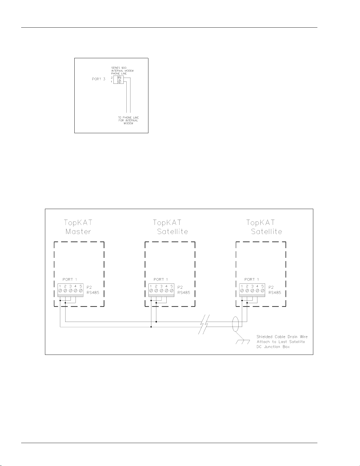
Mechanical Interface Option Wiring Diagrams
Figure 7-27: Wiring Diagram: Internal Modem
Notes:1) In cases where a TopKAT internal modem is used, Port 3 is not available for external
communication wiring.
2) The K2 jumper for Port 3 should be removed. Refer to “Terminal Block ID” on
page 42 for the location of the K2 jumper.
Figure 7-28: Wiring Diagram: TopKAT Master/Satellite Communications Wiring
Page 72 MDE-4319E TopKAT™ Fuel Management System Installation Manual · August 2008
Page 79

Wiring for Modems Mechanical Interface Option
Figure 7-29: Wiring Diagram: CRT Terminal and Okidata Printer
CRT Terminal (M07339B001)
and Keyboard (Q13181-02)
Okidata ML 186 Printer with
Super-speed Serial I/F (Part
Number PA03730000)
*Part Number C03813 is the
combination of M07339B001,
Q13181-02 and C01633
Wiring for Modems
External Modems
The type of phone line required for communication via an external modem depends upon the
type of modem used and the method of communication desired. Refer to the manual that is
provided with the modem, for specific requirements.
Internal Modem
When the To pKAT internal modem is installed, Port 3 communication is routed through the
modem in place of being wired at the DC Junction box. Jumper K2 should be removed. Refer
to
“Terminal Block ID” on page 42 for location of jumpers K1 and K2. The phone line for the
internal modem can be installed in the DC conduit. If you are installing it in the DC conduit,
the cable must be two twisted-pair shielded cable as specified in
Requirements” on page 19 and the shield drain wire must be connected to the system AC
ground. Check with your local phone company for proper installation of the phone line.
“Communication
MDE-4319E TopKAT™ Fuel Management System Installation Manual · August 2008 Page 73
Page 80

Mechanical Interface Option Wiring for Modems
This page is intentionally left blank.
Page 74 MDE-4319E TopKAT™ Fuel Management System Installation Manual · August 2008
Page 81

Description Mechanical PCU Option
8 – Mechanical PCU Option
Description
The Mechanical PCU option for the TopKAT syst em allows the unit to control fueling and
gather information from up to eight mechanical hose outlets (Four per PCU, with a maximum
of two PCUs). The TopKAT system with Mechanical PCU configuration is mounted on top of
a pedestal. PCUs can be mounted within the pedestal or wall-mounted.
• PCUs mounted within the pedestal require a large square pedestal. When using pedestalmounted PCUs, all pump/dispenser wiring connections are made within the TopKAT
system pedestal.
• Wall-mounted PCUs use a triangular pedestal. When using wall-mounted PCUs, all pump/
dispenser wiring connections are made within the wall-mounted PCUs.
The TopKAT system with the Mechanical PCU option can also be used in a master/satellite
configuration.
The mechanical PCU includes two solid-state relays and one manual override switch for each
hose outlet, which control power to the fuel dispensing equipment (for the override switches to
place the pump in MANUAL position, individual PCU power must be present). The TopKAT
system can handle quantity pulsing rates of 1, 10, 100, 500, and 1000 per gallon measurement
and 1, 10, 100 and 250 per liter measurement.
PCU Dimensions and Layouts
See the following figures for dimension and layout information:
• Figure 8-1 on page 76
• Figure 8-2 on page 77
• Figure 8-3 on page 78
• Figure 8-4 on page 79
MDE-4319E TopKAT™ Fuel Management System Installation Manual · August 2008 Page 75
Page 82

Mechanical PCU Option PCU Dimensions and Layouts
Figure 8-1: Pedestal Dimensions - Pedestal-mounted PCU
Page 76 MDE-4319E TopKAT™ Fuel Management System Installation Manual · August 2008
Page 83

PCU Dimensions and Layouts Mechanical PCU Option
Figure 8-2: Wall-mount PCU Dimensions
MDE-4319E TopKAT™ Fuel Management System Installation Manual · August 2008 Page 77
Page 84

Mechanical PCU Option PCU Dimensions and Layouts
Figure 8-3: Conduit Layout - Pedestal PCU
Page 78 MDE-4319E TopKAT™ Fuel Management System Installation Manual · August 2008
Page 85

PCU Dimensions and Layouts Mechanical PCU Option
Figure 8-4: Conduit Layout - Wall-mounted PCU
Note: Refer to “General Installation” on page 11 for conduit, power requirements, and wire
size considerations.
MDE-4319E TopKAT™ Fuel Management System Installation Manual · August 2008 Page 79
Page 86

Mechanical PCU Option Terminal Block ID
Terminal Block ID
To gain access to the inside of the TopKAT system, proceed as follows:
1 Unlock the rear door and open it completely.
2 Unscrew the two captive screws holding the hood in place.
3 Slide the hood toward the rear of the unit (about 1 inch) and lift it straight up.
See the following figures for Terminal Block ID information:
• Figure 8-5 on page 81
• Figure 8-6 on page 82
• Figure 8-7 on page 83
Page 80 MDE-4319E TopKAT™ Fuel Management System Installation Manual · August 2008
Page 87
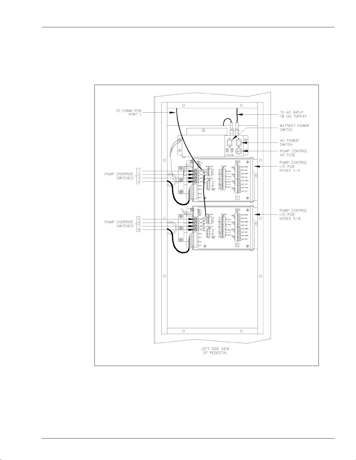
Terminal Block ID Mechanical PCU Option
Figure 8-5 shows the mechanical PCU components. Refer to “T erminal Block ID” on page 24
for the TopKAT Comm Assembly.
Figure 8-5: Terminal Block ID: Standard Pedestal - Left Side
MDE-4319E TopKAT™ Fuel Management System Installation Manual · August 2008 Page 81
Page 88

Mechanical PCU Option Terminal Block ID
Figure 8-6: Terminal Block ID: Standard Pedestal - Right Side
Page 82 MDE-4319E TopKAT™ Fuel Management System Installation Manual · August 2008
Page 89

Terminal Block ID Mechanical PCU Option
Figure 8-7: Terminal Block ID: Wall-mounted PCU
MDE-4319E TopKAT™ Fuel Management System Installation Manual · August 2008 Page 83
Page 90

Mechanical PCU Option Pump Control EXPMUX CPU Board
Pump Control EXPMUX CPU Board
1 Unlock and open the front door of the wall-mounted pump control unit or open the pedestal
access.
2 Ensure that all override switches are in the AUTO position. See Figure 8-8.
3 Ensure that the AC power and battery switches located in the upper right corner of the power
supply are turned off (down).
4 Loosen the screw for the card cage section, and swing out the card cage.
5 Remove the pump control EXPMUX CPU board (Figure 8-8), located in the rear portion of
the card cage, by pulling the top white tab.
6 Locate the K1 jumper patch and install the jumper. This jumper allows battery voltage to the
RAM. It should be installed for normal operation and removed for storage to prevent battery
discharge.
Figure 8-8: EXPMUX CPU Board
7 Verify if the pump control CPU board switch bank, SB (1 through 4), is set for the proper
address.
Page 84 MDE-4319E TopKAT™ Fuel Management System Installation Manual · August 2008
Page 91

Pump Control EXPMUX CPU Board Mechanical PCU Option
An address must be set to identify the pump control unit when it is connected to the TopKAT
system. This address is a unique identifier for multiple PCUs that are connected on the same
RS-485 line. Addressing should start at 1 and continue sequentially through 16. The physical
wiring order does not have to correspond with the address order, that is, the first unit on the
RS-485 line does not have to be address 1.
Switches 1 through 4 denote the address. This is factory set and does not have to be corrected.
The table below provides the switch settings for the address selections.
SB-1 SB-2 SB-3 SB-4
Address
1 Closed Closed Closed Closed
2 Open Closed Closed Closed
3 Closed Open Closed Closed
4 Open Open Closed Closed
5 Closed Closed Open Closed
6 Open Closed Open Closed
7 Closed Open Open Closed
8 Open Open Open Closed
9 Closed Closed Closed Open
10 Open Closed Closed Open
11 Closed Open Closed Open
12 Open Open Closed Open
13 Closed Closed Open Open
14 Open Closed Open Open
15 Closed Open Open Open
16 Open Open Open Open
ADDR1 ADDR2 ADDR3 ADDR4
8 Switches SB-5 through SB-8 are not relevant to the op eratio n of this uni t and should be set to
Closed.
9 The settings for switch bank SC (1 through 4) determine when the pump control unit begins
counting pulses for a particular pump. When a switch is open, the PCU begins counting pulses
when the corresponding pump is activated. When a switch is closed, as it should be for most
configurations using mechanical pumps, the PCU does not count pulses for the corresponding
pump until the mechanical reset has completed. The table below provides the switch settings
for SC-1 through SC-4.
Switch Function
SC-1 Mode pump 1 Open = Normal, Closed = Reset Complete
SC-2 Mode pump 2 Open = Normal, Closed = Reset Complete
SC-3 Mode pump 3 Open = Normal, Closed = Reset Complete
SC-4 Mode pump 4 Open = Normal, Closed = Reset Complete
MDE-4319E TopKAT™ Fuel Management System Installation Manual · August 2008 Page 85
Page 92

Mechanical PCU Option Pump Control EXPMUX CPU Board
10 In switch bank SC, between 5 through 8, only switch 6 and 8 are active. Switch SC-6 is the
Deadman Timer Switch. If enabled, the pump control unit must be polled at least every 15
seconds by the TopKAT. If it fails to sense a poll at that time, it turns off all relays. If Reset
Complete Mode is used on any pump on a particular PCU, the deadman timer should be
disabled. Switch SC-8 enables the test mode allowing the basic PCU functions to be tested
without the use of a site controller.
The table below gives the switch settings for SC-5 through SC-8.
Switch Function
SC-5 No function in on-line mode
SC-6 DEAD Open = deadman timer enabled
SC-7 No function in on-line mode
SC-8 TEST Open = Test mode, Closed = On-line mode
11 Reinstall the EXPMUX Pump Control CPU board.
Page 86 MDE-4319E TopKAT™ Fuel Management System Installation Manual · August 2008
Page 93
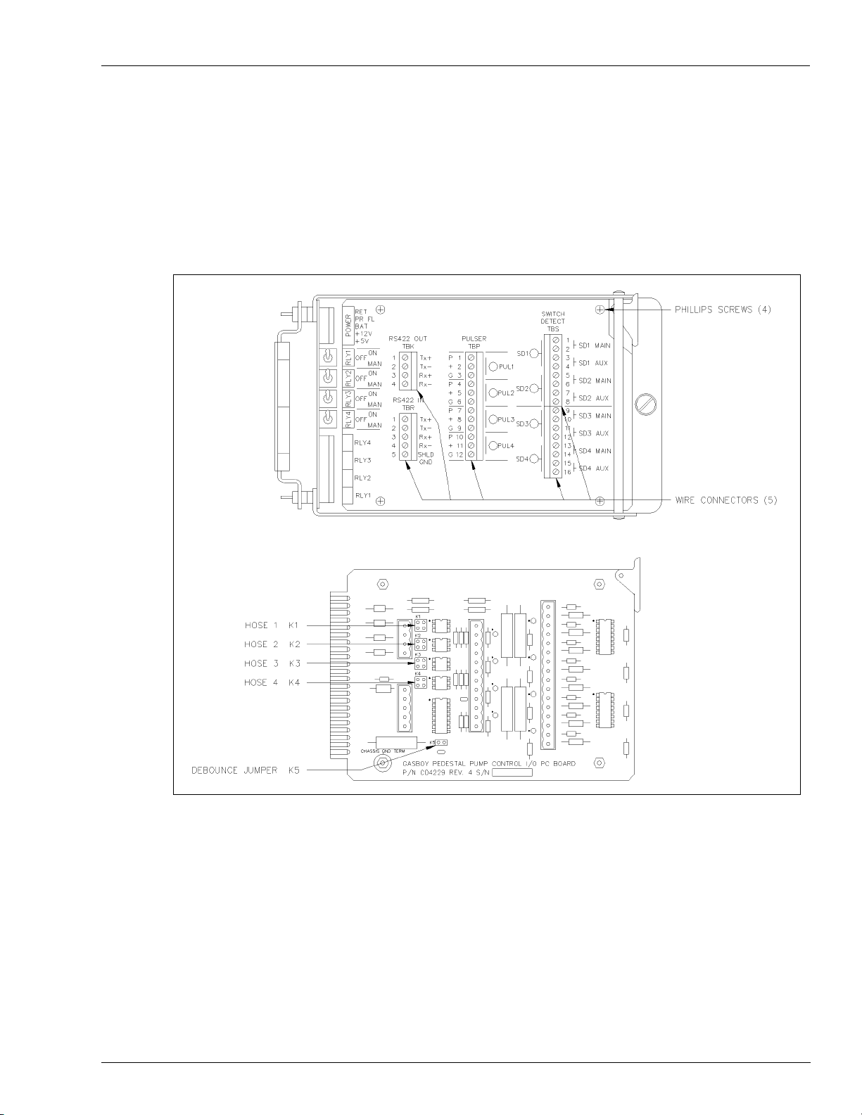
Pump Control I/O PCB Mechanical PCU Option
Pump Control I/O PCB
The Pump Control I/O PCB, shown in Figure 8-9, consists of two parts, the PCB and a cover
plate. T o set the jumpers and switches on the I/O PCB, you must remove all the connectors and
the cover plate.
Figure 8-9: Pump Control I/O Cover Plate and PCB
1 Remove the five green connectors from the front of the Pump Control I/O board.
2 Remove the board from the card cage in the same manner as the EXPMUX Pump Control
CPU board (see step
3 Remove the four Phillips
5 below “Pump Control EXPMUX CPU Board” on page 84).
®
screws securing the cover plate to the PCB and remove the cover
plate.
MDE-4319E TopKAT™ Fuel Management System Installation Manual · August 2008 Page 87
Page 94

Mechanical PCU Option Pump Control I/O PCB
4 Pulse Connection: Verify if the K1 through K4 jumpers (pulse type jumpers) match the Type
pulser being used for each pump position. Use the following table to determine your settings.
CAUTION
K1 to K4 jumpers must be set in the configurations shown below before turning on power to the
PCU or damage to the system components may occur.
Jumper Pin Function Voltage
VR Reed Switch Pulser, 1871 Series
P Pulser signal input (sink) 12 VDC square wave signal when pulsing
1
+ No connection
2
K1
VR Electronic Pulser, 7671 Series
K1
VR Totalizer Pulser, 7874 Series
K1
G DC ground for pulser DC ground
P Pulser signal input (sink) 12 VDC square wave signal when pulsing
1
+ +12 VDC supply voltage for pulser +12 VDC
2
G DC ground for pulser DC ground
P Pulser signal input (sink) Square wave signal when pulsing
1
+ Voltage for opto-isolator from pulser Voltage level of pulser
2
G DC ground for pulser DC ground
5 Debounce Configuration: Verify if the K5 jumper (debounce) is set properly as per the
following table. The K5 jumper should remain jumpered for all Reed Switch Quantity pulsers
and unjumpered for all Electronic and Money pulsers.
Jumper Speed Function
K5 Jumpered
K5 Open
Slow 10:1 quantity pulsers
Fast 10:1 money pulsers
All electronic pulsers
6 Replace the cover plate on the pump control I/O board and reinstall the board into the card
cage.
7 Replace the five green connectors into the proper sockets on the front of the Pump Control I/O
board (
Figure 8-9 on page 87).
8 Repeat all steps for both the EXPMUX Pump Control CPU and Pump Control I/O PCBs for
each PCU.
Page 88 MDE-4319E TopKAT™ Fuel Management System Installation Manual · August 2008
Page 95

System Pump and Dispenser Wiring Mechanical PCU Option
System Pump and Dispenser Wiring
Wiring Precautions
!
WARNING
To reduce the risk of electrical shock when servicing, turn off all power to the pump/
dispenser. In submersible pump applications, turn off all power to the submersible pump
and any other dispensers which use that submersible pump. AC power can feed back into a
shut off dispenser when dispensers share a common submersible pump or starter relay.
!
AVERTISSEMENT
Pour réduire le risque de choc électrique lors de l'entretien/révision, coupez totalement le
courant à la pompe/distributeur. Dans les applications de pompe immersible, coupez
totalement le courant à la pompe immersible et tous autres distributeurs qui utilisent la
pompe immersible. Le courant alternatif peut alimenter de nouveau un distributeur à l'arrêt
quand les distributeurs partagent une pompe immersible commune ou un relais de
démarrage.
The quality of the electrical installation is a major factor in maintaining proper safety levels
and providing trouble-free operation of your Gasboy pump/dispenser. To ensure a quality
installation, follow these rules:
• All wiring must be installed and used in accordance with local building/fire codes, all
Federal, State, and Local codes, the National Electrical Code (NFPA 70), NFPA 30, and
the Automotive and Marine Service Station Code (NFPA 30A) codes and regulations.
Canadian users must also comply with the Canadian Electrical Code.
• Use approved conduit and insulated gasoline and oil resistant copper wiring of the proper
size.
• Wire connections must be tightly spliced and secured with a wire nut. Close of f the open
end of the wire nut with electrical tape.
• Install an emergency power cutoff. In addition to circuit breaker requirements of NFPA
70, NFPA 30, NFPA 30A and the Canadian Electrical Code (Canadian users only), a
single control which simultaneously removes AC power from all site dispensing
equipment is recommended. This control must be readily accessible, clearly labeled, and
in accordance with local codes.
In order to provide the highest level of safety to you, your employees, and customers, all
employees must be trained as to the location of the power supply and the procedure for turning
off power to the entire system.
MDE-4319E TopKAT™ Fuel Management System Installation Manual · August 2008 Page 89
Page 96

Mechanical PCU Option Control Lines for Mechanical Pumps/Dispensers
Control Lines for Mechanical Pumps/Dispensers
Descriptions of the control lines are provided to familiarize the installer with the control inputs
and outputs that are used to control a mechanical pump/dispenser. Reading these descriptions
will give the installer a better working knowledge of the system and aid in planning the site
wiring.
Grounding
T o ensure proper operation of the equipment and provide the necessary safety factors, this unit
must be grounded. A ground wire (preferably green) must be connected between the ground
wire of the system and the main electrical service panel. One earth ground connection is
required for each unit. A ground rod must be installed at the main electrical panel in
accordance with the National Electrical Code. This ground rod must be a solid, corrosionresistant conductor. It should be properly tied into the ground bus strip of the panel. We
recommend the neutral and ground bus strips be bonded together (unless prohibited by local
codes).
Reset Motor Feed
This is a 115 VAC input which is supplied through the pump handle switch to activate the
reset motor. This line should be switched through the TopKAT system and should only be on
when the pump/dispenser is authorized or in manual mode. Without power supplied to this
line, the pump/dispenser will not reset when the pump handle is turned on. Two feed lines are
provided for twins. This feed is also connected to the input of one of the internal switches of
the electric reset. When the reset finishes its cycle, the 115 VAC input to the switch will be
passed through as an output, causing the solenoid valve (optional in some models) to open and
the Reset Complete line to indicate 115 VAC.
Pump Motor Feed
This is a 115 VAC input which is supplied to the input side of one of the internal switches of
the electric reset. This line should be switched through the TopKAT system and should only
be on when the pump/dispenser is authorized or in the Manual mode. When the reset finishe s
its cycle, the 115 VAC input to the switch is passed through as an output causing the pump
motor to receive power and begin fueling. Without power to this line, the unit will reset, but
will be unable to fuel. Two feed lines are provided in twins, which contain two motors. The
gauge of this wire (and its neutral wire) should be determined according to the size of the
motor, the voltage at which the motor will be powered (115 VAC or 230 VAC), and the
distance from the breaker panel to the pump. It is possible to combine the pump motor feeds
for twins and supply them from one breaker. However, the gauge of the wire needs to be
adjusted to handle the load of two motors.
Note: 230 VAC is developed across a motor when the other leg of the motor is connected to a
Phase 2 Feed.
Page 90 MDE-4319E TopKAT™ Fuel Management System Installation Manual · August 2008
Page 97

Control Lines for Mechanical Pumps/Dispensers Mechanical PCU Option
Neutral Feed
This is the AC current return line to the breaker panel for all attached devices (pump motor,
reset motor, solenoid valves). The gauge of this wire must be equal to that of the pump motor
feed (suction pumps) or submersible feed (dispensers).
Submersible Feed, Submersible Drive
This is a 115 VAC input which is supplied to the input side of one of the internal switches of
the electric reset. This line should be switched through the TopKAT system and only be on
when the pump/dispenser is authorized or in manual mode. When the reset finishes its cycle,
the 115 VAC input to the switch is passed through as an output (submersible drive) to drive a
starter relay or to directly drive a submersible motor up to 3/4 HP at 115 VAC or 1-1/2 HP at
230 VAC. Any submersible motor exceeding this limitation must use a starter relay.
Note: 230 VAC is developed across a motor when the other leg of the motor is connected to a
Phase 2 Feed.
Reset Complete (Switch Detect)
This is a 115 VAC output which is used to indicate if the reset is complete and the pump/
dispenser is ready to dispense the product. Two lines are provided for twins. This line should
only be used when monitoring of the pump/dispenser is desired (such as when used with a fuel
management system). This line must be capped when not in use.
Light Feed
This is a 115 VAC input required to power optional fluorescent lights that may be available in
a pump/dispenser. In a site configuration using multiple dispensers (or pumps), the power for
the lights of up to eight units can be supplied by one breaker. The light feed is not controlled
by the TopKAT system.
Light Neutral
This is a return line for AC current from the lights to the breaker panel.
Phase 2 Feed
This is a hot feed which is the opposite phase of the pump motor feed. This line and the pump
motor feed are used for 230 VAC motor applications.
Pulser - Mechanical Pump
This supplies a DC output which is provided to indicate the quantity dispensed.
MDE-4319E TopKAT™ Fuel Management System Installation Manual · August 2008 Page 91
Page 98

Mechanical PCU Option Wiring Diagrams: Pulsers, Pumps, Dispensers
Wiring Diagrams: Pulsers, Pumps, Dispensers
Mechanical PCU Option wiring diagrams are as follows:
• Figure 8-10: Wiring Diagram: Pulsers on page 93
• Figure 8-11: Wiring Diagram: Single Suction Pump, Veeder-Root Reset on page 95
• Figure 8-12: Wiring Diagram: Twin Suction Pump, Veeder-Root Reset on page 96
• Figure 8-13: Wiring Diagram: Twin Suction Pump, Single Motor, Veeder-Root Reset on
page 97
• Figure 8-14: Wiring Diagram: Single Remote Dispenser, Veeder-Root Reset on page 98
• Figure 8-15: Wiring Diagram: Twin Re mote Dispenser, Veeder-Root Reset on page 99
• Figure 8-16: Wiring Diagram: Single Suction Pump, Gasboy Reset on page 100
• Figure 8-17: Wiring Diagram: Twin Suction Pump, Gasboy Reset on page 101
• Figure 8-18: Wiring Diagram: Twin Suction Pump, Single Motor, Gasboy Reset on
page 102
• Figure 8-19: Wiring Diagram: Single Remote Dispenser, Gasboy Reset on page 103
• Figure 8-20: Wiring Diagram: Twin Remote Dispenser, Gasboy Reset on page 104
Page 92 MDE-4319E TopKAT™ Fuel Management System Installation Manual · August 2008
Page 99

Wiring Diagrams: Pulsers, Pumps, Dispensers Mechanical PCU Option
Figure 8-10: Wiring Diagram: Pulsers
MDE-4319E TopKAT™ Fuel Management System Installation Manual · August 2008 Page 93
Page 100

Mechanical PCU Option Wiring Diagrams: Pulsers, Pumps, Dispensers
Pulser Wiring Notes
Notes: 1) All the pulsers shown above are connected to Hose 1.
2) Jumpers on the Pump Control PCB must be properly jumpered according to the
pulser type. This should be done by the person performing the start-up. Power to the
system must not be turned on prior to this setup.
3) Refer to “Conduit Layout/Installation Specifications” on page 14 for detailed system
installation specifications.
4) When installed in a separate DC conduit, 18 AWG wires are required for
installation. Although it is recommended that DC pulser wires be run in a separate
conduit away from AC wires, they can be combined in the same conduit with AC
wires providing UL-listed cable with the following specifications is used:
• Conductor: 18 AWG stranded wire. Number of conductors to be determined by
pulser
• Shield: Foil-wrapped 100% coverage and/or tinned copper braid 90% coverage
• Drain Wire: Stranded, tinned copper, 20 AWG or larger/or braided shield
• Voltage Rating: Maximum operating voltage of 600 V
• Environmental: Gas- and oil-resistant; suitable for wet or dry locations.
Gasboy can supply Belden 1063A (part number C09655) which is a UL-listed, 4-conductor
cable that meets the requirements listed above.
Note: Belden 1063A is UL-listed but not CSA-listed.
Page 94 MDE-4319E TopKAT™ Fuel Management System Installation Manual · August 2008
 Loading...