

Page 1

TopKAT™ Fuel Management System
Operation Manual
MDE-4338A
Page 2

Computer Programs and Documentation
Federal Communications Commission (FCC) Warning
All Gasboy computer programs (including software on diskettes and within memory chips) and documentation are copyrighted by, and shall remain the property of, Gasboy. Such
computer programs and documents may also contain trade secret information. The duplication, disclosure, modification, or unauthorized use of computer programs or
documentation is strictly prohibited, unless otherwise licensed by Gasboy.
This equipment has been tested and found to comply with the limits for a Class A digital device pursuant to Part 15 of the FCC Rules. These limits are designed to provide
reasonable protection against harmful interference when the equipment is operated in a commercial environment. This equipment generates, uses, and can radiate radio frequency
energy, and if not installed and used in accordance with the instruction manual, may cause harmful interference to radio communications. Operation of this equipment in a
residential area is likely to cause harmful interference in which case the user will be required to correct the interference at his own expense. Changes or modifications not expressly
approved by the manufacturer could void the user’s authority to operate this equipment.
Approvals
Gasboy, Greensboro, is an ISO 9001:2000 registered facility.
Underwriters Laboratories (UL):
UL File# Products listed with UL
MH4314
MH6418
MH7404
MH10581 Key control unit, Model GKE-B Series
All dispensers and self-contained pumping
units
Power operated Transfer Pump Models 25,
25C, 26, 27, 28, 72, 72S, 72SP, 72X, 73 and
1820
Hand operated Transfer Pump Models 1230
Series, 1243 Series, 1520 and 1720 Series
Card reader terminals, Models 1000, 1000P
Site controller, Model 2000S CFN Series
Data entry terminals, Model TPK-900 Series
Fuel Point Reader System
New York City Fire Department (NYFD):
NYFD C of A # Product
4823 9100A, 9140A, 9152A, 9153A,
4997 9822A, 9823A
5046 9100Q, 9140Q, 9152Q, 9153Q,
5087 8753K, 8853K, 9153K, 9853K
5091 8752K, 9152K
5129 9122K, 9123K, 9822K, 9823K
9800A, 9840A, 9850A, 9852A,
9853A, 9140
9800Q, 9840Q, 9852Q, 9853Q
(restricted to diesel and nonretail gasoline sales)
National Conference of Weights and Measures (NCWM) - Certificate of Compliance (CoC):
Gasboy pumps and dispensers are evaluated by NCWM under the National Type Evaluation Program (NTEP). NCWM has issued the following CoC:
CoC# Product Model # CoC# Product Model # CoC# Product Model #
95-179 Dispenser
95-136 Dispenser 9800 Series 91-057 Controller
9100 Retail Series, 8700
Series, 9700 Series
91-019 Dispenser
9100 Commercial
Series
1000 Series FMS,
2000S-CFN Series
California Air Resources Board (CARB):
Executive Order # Product
G-70-52-AM Balance Vapor Recovery
G-70-150-AE VaporVac
05-002 Atlas
8700K, 8800K,
9100K, 9200K, 9800K
Patents
Gasboy products are manufactured or sold under one or more of the following US patents:
Dispensers
5,257,720
Point of Sale/Back Office Equipment
D335,673
Trademarks
Non-registered trademarks
Atlas™
Consola™
Infinity™
Registered trademarks
ASTRA
Fuel Point
Gasboy
Keytrol
Slimline
Additional US and foreign patents pending.
®
®
®
®
®
Additional US and foreign trademarks pending.
Other brand or product names shown may be
trademarks or registered trademarks of their
respective holders.
This document is subject to change without notice.
E-mail: literature@gasboy.com · Internet: http://www.gasboy.com
© 2009 GASBOY · All Rights Reserved
Page 3

Table of Contents
1 – Introduction 1
Abbreviations and Acronyms. . . . . . . . . . . . . . . . . . . . . . . . . . . . . . . . . . . . . . . . . . . . . . . . . . . . . . . . . . 2
Warranty . . . . . . . . . . . . . . . . . . . . . . . . . . . . . . . . . . . . . . . . . . . . . . . . . . . . . . . . . . . . . . . . . . . . . . . . . 4
2 – Important Safety Information 5
3 – System Overview 9
Hardware Description . . . . . . . . . . . . . . . . . . . . . . . . . . . . . . . . . . . . . . . . . . . . . . . . . . . . . . . . . . . . . . .9
CPU Printed Circuit Board. . . . . . . . . . . . . . . . . . . . . . . . . . . . . . . . . . . . . . . . . . . . . . . . . . . . . . . . . . . 10
CPU PCB Switch Settings . . . . . . . . . . . . . . . . . . . . . . . . . . . . . . . . . . . . 10
CPU LEDs . . . . . . . . . . . . . . . . . . . . . . . . . . . . . . . . . . . . . . . . . . . . . . . . 11
Battery Maintenance/Replacement . . . . . . . . . . . . . . . . . . . . . . . . . . . . . 12
Communications . . . . . . . . . . . . . . . . . . . . . . . . . . . . . . . . . . . . . . . . . . . . . . . . . . . . . . . . . . . . . . . . . . 12
Communications Ports . . . . . . . . . . . . . . . . . . . . . . . . . . . . . . . . . . . . . . . 12
Communications Protocol . . . . . . . . . . . . . . . . . . . . . . . . . . . . . . . . . . . .12
Initiating Communications . . . . . . . . . . . . . . . . . . . . . . . . . . . . . . . . . . . . 13
Operating Modes . . . . . . . . . . . . . . . . . . . . . . . . . . . . . . . . . . . . . . . . . . .13
9800 Switch Settings . . . . . . . . . . . . . . . . . . . . . . . . . . . . . . . . . . . . . . . .13
Report Printer Interface Option - Standalone or Master Only . . . . . . . . . . . . . . . . . . . . . . . . . . . . . . . . 15
Accessing the Printer . . . . . . . . . . . . . . . . . . . . . . . . . . . . . . . . . . . . . . . . 15
Printer Controller PCB . . . . . . . . . . . . . . . . . . . . . . . . . . . . . . . . . . . . . . . 15
Setting Switches. . . . . . . . . . . . . . . . . . . . . . . . . . . . . . . . . . . . . . . . . . . .16
Adjusting Contrast . . . . . . . . . . . . . . . . . . . . . . . . . . . . . . . . . . . . . . . . . . 16
Loading Paper . . . . . . . . . . . . . . . . . . . . . . . . . . . . . . . . . . . . . . . . . . . . . 17
PCMCIA Interface Option - Standalone or Master Only . . . . . . . . . . . . . . . . . . . . . . . . . . . . . . . . . . . . 18
PCMCIA Interface PCB . . . . . . . . . . . . . . . . . . . . . . . . . . . . . . . . . . . . . . 18
Master/Satellite (T/Net) Option . . . . . . . . . . . . . . . . . . . . . . . . . . . . . . . . . . . . . . . . . . . . . . . . . . . . . . . 19
Mechanical Interface Option . . . . . . . . . . . . . . . . . . . . . . . . . . . . . . . . . . . . . . . . . . . . . . . . . . . . . . . . . 20
Hardware . . . . . . . . . . . . . . . . . . . . . . . . . . . . . . . . . . . . . . . . . . . . . . . . . 20
Software . . . . . . . . . . . . . . . . . . . . . . . . . . . . . . . . . . . . . . . . . . . . . . . . . . 20
Mechanical PCU Option . . . . . . . . . . . . . . . . . . . . . . . . . . . . . . . . . . . . . . . . . . . . . . . . . . . . . . . . . . . . 21
Hardware . . . . . . . . . . . . . . . . . . . . . . . . . . . . . . . . . . . . . . . . . . . . . . . . . 21
Software . . . . . . . . . . . . . . . . . . . . . . . . . . . . . . . . . . . . . . . . . . . . . . . . . . 21
Typical Fueling Sequence - Standalone or Master/Satellite . . . . . . . . . . . . . . . . . . . . . . . . . . . . . . . . . 22
Delivery or Dipstick Key Sequence . . . . . . . . . . . . . . . . . . . . . . . . . . . . . . . . . . . . . . . . . . . . . . . . . . . . 24
Supervisor Key Sequence . . . . . . . . . . . . . . . . . . . . . . . . . . . . . . . . . . . . . . . . . . . . . . . . . . . . . . . . . . . 24
4 – Getting Started/System Setup 25
Setting Up the System. . . . . . . . . . . . . . . . . . . . . . . . . . . . . . . . . . . . . . . . . . . . . . . . . . . . . . . . . . . . . . 25
Navigating the Keypad . . . . . . . . . . . . . . . . . . . . . . . . . . . . . . . . . . . . . . . . . . . . . . . . . . . . . . . . . . . . . 25
Setting Up Your System for the First Time . . . . . . . . . . . . . . . . . . . . . . . . . . . . . . . . . . . . . . . . . . . . . . 26
Keypad Setup for Standalone or Master Mode . . . . . . . . . . . . . . . . . . . . 26
Keypad Setup for Satellite Mode . . . . . . . . . . . . . . . . . . . . . . . . . . . . . . . 28
Terminal Mode Setup. . . . . . . . . . . . . . . . . . . . . . . . . . . . . . . . . . . . . . . . 29
Accessing the Main Menu Options . . . . . . . . . . . . . . . . . . . . . . . . . . . . . . . . . . . . . . . . . . . . . . . . . . . . 30
Setup Menu . . . . . . . . . . . . . . . . . . . . . . . . . . . . . . . . . . . . . . . . . . . . . . . . . . . . . . . . . . . . . . . . . . . . . . 30
Accessing the Setup Commands . . . . . . . . . . . . . . . . . . . . . . . . . . . . . . . 30
MDE-4338A TopKAT™ Fuel Management System Operation Manual · February 2009 Page i
Page 4

5 – Vehicle File Setup - Keypad 35
About the Vehicle File. . . . . . . . . . . . . . . . . . . . . . . . . . . . . . . . . . . . . . . . . . . . . . . . . . . . . . . . . . . . . . 35
Limitation Codes. . . . . . . . . . . . . . . . . . . . . . . . . . . . . . . . . . . . . . . . . . . . . . . . . . . . . . . . . . . . . . . . . . 36
Authorization Codes . . . . . . . . . . . . . . . . . . . . . . . . . . . . . . . . . . . . . . . . . . . . . . . . . . . . . . . . . . . . . . . 37
Check Digit . . . . . . . . . . . . . . . . . . . . . . . . . . . . . . . . . . . . . . . . . . . . . . . . . . . . . . . . . . . . . . . . . . . . . . 37
Lockout . . . . . . . . . . . . . . . . . . . . . . . . . . . . . . . . . . . . . . . . . . . . . . . . . . . . . . . . . . . . . . . . . . . . . . . . . 38
PIN . . . . . . . . . . . . . . . . . . . . . . . . . . . . . . . . . . . . . . . . . . . . . . . . . . . . . . . . . . . . . . . . . . . . . . . . . . . . 38
Vehicle Record Maintenance . . . . . . . . . . . . . . . . . . . . . . . . . . . . . . . . . . . . . . . . . . . . . . . . . . . . . . . . 39
Edit/View Record. . . . . . . . . . . . . . . . . . . . . . . . . . . . . . . . . . . . . . . . . . . 39
Add Vehicle Record . . . . . . . . . . . . . . . . . . . . . . . . . . . . . . . . . . . . . . . . 39
Delete Vehicle Record . . . . . . . . . . . . . . . . . . . . . . . . . . . . . . . . . . . . . . 40
Encode Key. . . . . . . . . . . . . . . . . . . . . . . . . . . . . . . . . . . . . . . . . . . . . . . 41
Initialize File . . . . . . . . . . . . . . . . . . . . . . . . . . . . . . . . . . . . . . . . . . . . . . 42
Clear File. . . . . . . . . . . . . . . . . . . . . . . . . . . . . . . . . . . . . . . . . . . . . . . . . 42
6 – Manual Entry File Setup - Keypad 43
About the Manual Entry File . . . . . . . . . . . . . . . . . . . . . . . . . . . . . . . . . . . . . . . . . . . . . . . . . . . . . . . . . 43
Manual Entry File Maintenance . . . . . . . . . . . . . . . . . . . . . . . . . . . . . . . . . . . . . . . . . . . . . . . . . . . . . . 44
Accessing the Manual Entry File . . . . . . . . . . . . . . . . . . . . . . . . . . . . . . . 44
Edit/View Manual Entry . . . . . . . . . . . . . . . . . . . . . . . . . . . . . . . . . . . . . . 44
Add Manual Entry Record . . . . . . . . . . . . . . . . . . . . . . . . . . . . . . . . . . . . 44
Delete Manual Entry Record . . . . . . . . . . . . . . . . . . . . . . . . . . . . . . . . . . 45
Initialize File . . . . . . . . . . . . . . . . . . . . . . . . . . . . . . . . . . . . . . . . . . . . . . 45
Clear File. . . . . . . . . . . . . . . . . . . . . . . . . . . . . . . . . . . . . . . . . . . . . . . . . 45
7 – Tank, Pump, and PCU File Setup - Keypad 47
About the Tank File . . . . . . . . . . . . . . . . . . . . . . . . . . . . . . . . . . . . . . . . . . . . . . . . . . . . . . . . . . . . . . . 47
Access the Tank File. . . . . . . . . . . . . . . . . . . . . . . . . . . . . . . . . . . . . . . . 47
Load # of Tanks . . . . . . . . . . . . . . . . . . . . . . . . . . . . . . . . . . . . . . . . . . . 47
Initialize File . . . . . . . . . . . . . . . . . . . . . . . . . . . . . . . . . . . . . . . . . . . . . . 48
Load Tank Table . . . . . . . . . . . . . . . . . . . . . . . . . . . . . . . . . . . . . . . . . . . 48
Add to Inventory . . . . . . . . . . . . . . . . . . . . . . . . . . . . . . . . . . . . . . . . . . . 48
Subtract from Inventory . . . . . . . . . . . . . . . . . . . . . . . . . . . . . . . . . . . . . . 49
About the Pump File . . . . . . . . . . . . . . . . . . . . . . . . . . . . . . . . . . . . . . . . . . . . . . . . . . . . . . . . . . . . . . . 49
Access the Pump File . . . . . . . . . . . . . . . . . . . . . . . . . . . . . . . . . . . . . . . 49
Initialize File . . . . . . . . . . . . . . . . . . . . . . . . . . . . . . . . . . . . . . . . . . . . . . 49
Load # of Pumps (Standalone TopKAT, Master Electronic,
Master Mechanical PCU) . . . . . . . . . . . . . . . . . . . . . . . . . . . . . . . . . . . . 50
Load Base Pump (Standalone TopKAT and Master Electronic,
Master Mechanical PCU) . . . . . . . . . . . . . . . . . . . . . . . . . . . . . . . . . . . . 50
Load Pump Table . . . . . . . . . . . . . . . . . . . . . . . . . . . . . . . . . . . . . . . . . . 50
Load Pump Timeouts . . . . . . . . . . . . . . . . . . . . . . . . . . . . . . . . . . . . . . . 51
About the PCU File. . . . . . . . . . . . . . . . . . . . . . . . . . . . . . . . . . . . . . . . . . . . . . . . . . . . . . . . . . . . . . . . 52
Access PCU Setup . . . . . . . . . . . . . . . . . . . . . . . . . . . . . . . . . . . . . . . . . 52
PCU Setup/PCU Assignments (Standalone, All Electronic; Master,
All Electronic; Mechanical PCUs) . . . . . . . . . . . . . . . . . . . . . . . . . . . . . . 52
PCU Assignments/Edit PCUs (Master Mechanical I/F,
Master Combination). . . . . . . . . . . . . . . . . . . . . . . . . . . . . . . . . . . . . . . . 53
Page ii MDE-4338A TopKAT™ Fuel Management System Operation Manual · February 2009
Page 5

8 – Transaction File Setup - Keypad 55
About the Transaction File. . . . . . . . . . . . . . . . . . . . . . . . . . . . . . . . . . . . . . . . . . . . . . . . . . . . . . . . . . . 55
Config Trans File . . . . . . . . . . . . . . . . . . . . . . . . . . . . . . . . . . . . . . . . . . . . . . . . . . . . . . . . . . . . . . . . . . 56
Move Trans Pointer . . . . . . . . . . . . . . . . . . . . . . . . . . . . . . . . . . . . . . . . . 56
Load Trans Number . . . . . . . . . . . . . . . . . . . . . . . . . . . . . . . . . . . . . . . . . 56
Clear Trans in Prog . . . . . . . . . . . . . . . . . . . . . . . . . . . . . . . . . . . . . . . . . 56
Clear Trans File . . . . . . . . . . . . . . . . . . . . . . . . . . . . . . . . . . . . . . . . . . . . 56
Record Error Trans . . . . . . . . . . . . . . . . . . . . . . . . . . . . . . . . . . . . . . . . . 57
Config Trans Logger . . . . . . . . . . . . . . . . . . . . . . . . . . . . . . . . . . . . . . . . 57
Memory Full Protection . . . . . . . . . . . . . . . . . . . . . . . . . . . . . . . . . . . . . . 57
9 – Modem Initialization - Keypad 59
About Modem Initialization . . . . . . . . . . . . . . . . . . . . . . . . . . . . . . . . . . . . . . . . . . . . . . . . . . . . . . . . . . 59
PRINT MODEM INIT . . . . . . . . . . . . . . . . . . . . . . . . . . . . . . . . . . . . . . . . . . . . . . . . . . . . . . . . . . . . . . . 60
INIT MODEM . . . . . . . . . . . . . . . . . . . . . . . . . . . . . . . . . . . . . . . . . . . . . . . . . . . . . . . . . . . . . . . . . . . . . 60
10 – Serial-to-LAN Configuration 61
11 – Wireless Communications Configuration 63
12 – Reports 65
About Reports . . . . . . . . . . . . . . . . . . . . . . . . . . . . . . . . . . . . . . . . . . . . . . . . . . . . . . . . . . . . . . . . . . . . 65
Printing Reports. . . . . . . . . . . . . . . . . . . . . . . . . . . . . . . . . . . . . . . . . . . . . . . . . . . . . . . . . . . . . . . . . . . 65
Accessing the Report Menu . . . . . . . . . . . . . . . . . . . . . . . . . . . . . . . . . . . . . . . . . . . . . . . . . . . . . . . . . 65
Print Date/Time . . . . . . . . . . . . . . . . . . . . . . . . . . . . . . . . . . . . . . . . . . . . . . . . . . . . . . . . . . . . . . . . . . . 66
Print System Configuration (PRINT SYS CONFIG) . . . . . . . . . . . . . . . . . . . . . . . . . . . . . . . . . . . . . . .66
Department/Vehicle Report (DEPT/VEHICLE RPT) or
Account Vehicle Report (ACCT/VEHICLE RPT) . . . . . . . . . . . . . . . . . . . . . . . . . . . . . . . . . . . . . . . . . . 66
Inventory Report . . . . . . . . . . . . . . . . . . . . . . . . . . . . . . . . . . . . . . . . . . . . . . . . . . . . . . . . . . . . . . . . . . 67
Pump Report . . . . . . . . . . . . . . . . . . . . . . . . . . . . . . . . . . . . . . . . . . . . . . . . . . . . . . . . . . . . . . . . . . . . . 67
Vehicle File Report (VEH FILE REPORT). . . . . . . . . . . . . . . . . . . . . . . . . . . . . . . . . . . . . . . . . . . . . . . 68
Vehicle Lockout Report (VEH LOCKOUT REPORT) . . . . . . . . . . . . . . . . . . . . . . . . . . . . . . . . . . . . . . 68
Manual Entry Lockout Report (MAN LOCKOUT REPORT) . . . . . . . . . . . . . . . . . . . . . . . . . . . . . . . . . 68
Department Manual Entry Report (DEPT MAN ENT RPT) . . . . . . . . . . . . . . . . . . . . . . . . . . . . . . . . . . 69
Manual Entry Report . . . . . . . . . . . . . . . . . . . . . . . . . . . . . . . . . . . . . . . . . . . . . . . . . . . . . . . . . . . . . . . 69
Events Report . . . . . . . . . . . . . . . . . . . . . . . . . . . . . . . . . . . . . . . . . . . . . . . . . . . . . . . . . . . . . . . . . . . . 70
13 – Diagnostics and Utilities 71
About Diagnostics and Utilities . . . . . . . . . . . . . . . . . . . . . . . . . . . . . . . . . . . . . . . . . . . . . . . . . . . . . . . 71
Accessing the Keypad Diagnostics Menu . . . . . . . . . . . . . . . . . . . . . . . . . . . . . . . . . . . . . . . . . . . . . . . 72
Keypad Diagnostics Menu . . . . . . . . . . . . . . . . . . . . . . . . . . . . . . . . . . . . 72
Keypad: PCU STATUS . . . . . . . . . . . . . . . . . . . . . . . . . . . . . . . . . . . . . . 72
Keypad: RAM TEST. . . . . . . . . . . . . . . . . . . . . . . . . . . . . . . . . . . . . . . . . 72
Keypad: ROM TEST . . . . . . . . . . . . . . . . . . . . . . . . . . . . . . . . . . . . . . . .72
Keypad: DIP SWITCH TEST . . . . . . . . . . . . . . . . . . . . . . . . . . . . . . . . . . 73
Keypad: KEYPAD TEST . . . . . . . . . . . . . . . . . . . . . . . . . . . . . . . . . . . . . 73
Keypad: DISPLAY TEST . . . . . . . . . . . . . . . . . . . . . . . . . . . . . . . . . . . . . 73
Keypad: KEY READ TOTALIZER . . . . . . . . . . . . . . . . . . . . . . . . . . . . . . 73
Keypad: PROGRAM VERSION . . . . . . . . . . . . . . . . . . . . . . . . . . . . . . . . 74
Keypad: PORT TEST. . . . . . . . . . . . . . . . . . . . . . . . . . . . . . . . . . . . . . . . 74
MDE-4338A TopKAT™ Fuel Management System Operation Manual · February 2009 Page iii
Page 6

Keypad: DATAKEY READ . . . . . . . . . . . . . . . . . . . . . . . . . . . . . . . . . . . 74
Keypad: PCMCIA TEST . . . . . . . . . . . . . . . . . . . . . . . . . . . . . . . . . . . . . 75
Accessing the Utilities Menu. . . . . . . . . . . . . . . . . . . . . . . . . . . . . . . . . . . . . . . . . . . . . . . . . . . . . . . . . 75
PCMCIA Backup/Restore Utility (optional) . . . . . . . . . . . . . . . . . . . . . . . 76
Accessing the Terminal Diagnostics Menu. . . . . . . . . . . . . . . . . . . . . . . . . . . . . . . . . . . . . . . . . . . . . . 79
Terminal: RAM TEST . . . . . . . . . . . . . . . . . . . . . . . . . . . . . . . . . . . . . . . 80
Terminal: ROM TEST . . . . . . . . . . . . . . . . . . . . . . . . . . . . . . . . . . . . . . . 80
Terminal: DIP SWITCH TEST . . . . . . . . . . . . . . . . . . . . . . . . . . . . . . . . . 81
Terminal: HEALTH LIGHT TEST . . . . . . . . . . . . . . . . . . . . . . . . . . . . . . 81
Terminal: BEEPER TEST . . . . . . . . . . . . . . . . . . . . . . . . . . . . . . . . . . . . 82
Terminal: DISPLAY TEST. . . . . . . . . . . . . . . . . . . . . . . . . . . . . . . . . . . . 82
Terminal: KEYPAD TEST . . . . . . . . . . . . . . . . . . . . . . . . . . . . . . . . . . . . 83
Terminal: DATAKEY TEST . . . . . . . . . . . . . . . . . . . . . . . . . . . . . . . . . . . 83
Terminal: PORT TEST . . . . . . . . . . . . . . . . . . . . . . . . . . . . . . . . . . . . . . 83
Terminal: DEADMAN TIMER RESET . . . . . . . . . . . . . . . . . . . . . . . . . . . 84
Terminal: PCMCIA TEST . . . . . . . . . . . . . . . . . . . . . . . . . . . . . . . . . . . . 85
Terminal: PRINTER TEST . . . . . . . . . . . . . . . . . . . . . . . . . . . . . . . . . . . 86
14 – Terminal Commands 87
About Terminal Commands . . . . . . . . . . . . . . . . . . . . . . . . . . . . . . . . . . . . . . . . . . . . . . . . . . . . . . . . . 87
Accessing the Terminal Commands. . . . . . . . . . . . . . . . . . . . . . . . . . . . . . . . . . . . . . . . . . . . . . . . . . . 88
Add Inventory (A I) . . . . . . . . . . . . . . . . . . . . . . . . . . . . . . . . . . . . . . . . . 88
Add RECord (A REC) . . . . . . . . . . . . . . . . . . . . . . . . . . . . . . . . . . . . . . . 89
CLear File (CL F) . . . . . . . . . . . . . . . . . . . . . . . . . . . . . . . . . . . . . . . . . . 90
CLear Key (CL K) . . . . . . . . . . . . . . . . . . . . . . . . . . . . . . . . . . . . . . . . . . 90
CLear Transaction In Progress (CL TIP). . . . . . . . . . . . . . . . . . . . . . . . . 90
COnfigure Bulk (CO B) . . . . . . . . . . . . . . . . . . . . . . . . . . . . . . . . . . . . . . 91
COnfigure LOGger (CO LOG). . . . . . . . . . . . . . . . . . . . . . . . . . . . . . . . . 91
COnfigure MAnual (CO MA) . . . . . . . . . . . . . . . . . . . . . . . . . . . . . . . . . . 91
COnfigure PCUs (CO PC) - Standalone Electronic;
Master/Satellite Electronic; Mechanical PCUs . . . . . . . . . . . . . . . . . . . . 92
COnfigure PCus (CO PC) - Master/Satellite Mechanical;
Master/Satellite Combination . . . . . . . . . . . . . . . . . . . . . . . . . . . . . . . . . 92
COnfigure PIn (CO PI) . . . . . . . . . . . . . . . . . . . . . . . . . . . . . . . . . . . . . . 94
COnfigure SYstem (CO SY) - Standalone Electronic or
Mechanical PCU . . . . . . . . . . . . . . . . . . . . . . . . . . . . . . . . . . . . . . . . . . . 94
COnfigure SYstem (CO SY) - Standalone Mechanical . . . . . . . . . . . . . . 95
COnfigure SYstem (CO SY) - Master/Satellite Mechanical;
Master/Satellite Combination . . . . . . . . . . . . . . . . . . . . . . . . . . . . . . . . . 96
COnfigure SYstem (CO SY) - Master/Satellite Electronic or
Mechanical PCU . . . . . . . . . . . . . . . . . . . . . . . . . . . . . . . . . . . . . . . . . . . 97
COnfigure Units (CO U) . . . . . . . . . . . . . . . . . . . . . . . . . . . . . . . . . . . . . 98
DElete RECord (DE REC). . . . . . . . . . . . . . . . . . . . . . . . . . . . . . . . . . . . 98
DIAGnostics (DIAG) . . . . . . . . . . . . . . . . . . . . . . . . . . . . . . . . . . . . . . . . 99
DISable PUmp (DIS PU) . . . . . . . . . . . . . . . . . . . . . . . . . . . . . . . . . . . . . 99
EDit RECord (ED REC). . . . . . . . . . . . . . . . . . . . . . . . . . . . . . . . . . . . . . 99
ENable PRotection (EN PR) . . . . . . . . . . . . . . . . . . . . . . . . . . . . . . . . . 100
ENable PUmp (EN PU) . . . . . . . . . . . . . . . . . . . . . . . . . . . . . . . . . . . . . 100
EXit (EX) . . . . . . . . . . . . . . . . . . . . . . . . . . . . . . . . . . . . . . . . . . . . . . . . 100
Help (H). . . . . . . . . . . . . . . . . . . . . . . . . . . . . . . . . . . . . . . . . . . . . . . . . 100
INitialize File (I F) . . . . . . . . . . . . . . . . . . . . . . . . . . . . . . . . . . . . . . . . . 101
Initialize MODem (I MOD) . . . . . . . . . . . . . . . . . . . . . . . . . . . . . . . . . . . 101
Load DAte (L DA) . . . . . . . . . . . . . . . . . . . . . . . . . . . . . . . . . . . . . . . . . 102
LOad MODem (LO MOD) . . . . . . . . . . . . . . . . . . . . . . . . . . . . . . . . . . . 102
Page iv MDE-4338A TopKAT™ Fuel Management System Operation Manual · February 2009
Page 7

Load MOre (L MO) . . . . . . . . . . . . . . . . . . . . . . . . . . . . . . . . . . . . . . . . . 102
Load PAssword (L PA) . . . . . . . . . . . . . . . . . . . . . . . . . . . . . . . . . . . . . . 103
Load PUmp (L PU). . . . . . . . . . . . . . . . . . . . . . . . . . . . . . . . . . . . . . . . . 103
Load RAnge (L RA) . . . . . . . . . . . . . . . . . . . . . . . . . . . . . . . . . . . . . . . . 103
Load RETry (L RET) . . . . . . . . . . . . . . . . . . . . . . . . . . . . . . . . . . . . . . . 104
Load TAnk (L TA) . . . . . . . . . . . . . . . . . . . . . . . . . . . . . . . . . . . . . . . . . . 104
Load TIMe (L TIM) . . . . . . . . . . . . . . . . . . . . . . . . . . . . . . . . . . . . . . . . . 104
Load TRansactions (L TR) . . . . . . . . . . . . . . . . . . . . . . . . . . . . . . . . . . . 104
Move POinter (M PO). . . . . . . . . . . . . . . . . . . . . . . . . . . . . . . . . . . . . . . 105
PRint DAte (PR DA) . . . . . . . . . . . . . . . . . . . . . . . . . . . . . . . . . . . . . . . . 105
PRint DEPTMan (PR DEPTM) . . . . . . . . . . . . . . . . . . . . . . . . . . . . . . . . 105
PRint DEPTVeh (PR DEPTV) or PRint Acctveh (PR A) . . . . . . . . . . . . 106
PRint EVents (PR EV) . . . . . . . . . . . . . . . . . . . . . . . . . . . . . . . . . . . . . . 106
PRint KEy (PR KE). . . . . . . . . . . . . . . . . . . . . . . . . . . . . . . . . . . . . . . . .106
PRint LOCkout (PR LOC) . . . . . . . . . . . . . . . . . . . . . . . . . . . . . . . . . . . 107
PRint MAnual (PR MA) . . . . . . . . . . . . . . . . . . . . . . . . . . . . . . . . . . . . .107
Print MODem (P MOD) . . . . . . . . . . . . . . . . . . . . . . . . . . . . . . . . . . . . . 107
PRint PUmp (PR PU) . . . . . . . . . . . . . . . . . . . . . . . . . . . . . . . . . . . . . . . 107
PRint SYstem (PR SY). . . . . . . . . . . . . . . . . . . . . . . . . . . . . . . . . . . . . . 108
PRint TAnks (PR TA) . . . . . . . . . . . . . . . . . . . . . . . . . . . . . . . . . . . . . . . 108
PRint TRansaction (PR TR) . . . . . . . . . . . . . . . . . . . . . . . . . . . . . . . . . . 108
PRint Vehicle (PR V) . . . . . . . . . . . . . . . . . . . . . . . . . . . . . . . . . . . . . . . 108
REcord ERror (RE ER) . . . . . . . . . . . . . . . . . . . . . . . . . . . . . . . . . . . . . 108
RUN (RUN) . . . . . . . . . . . . . . . . . . . . . . . . . . . . . . . . . . . . . . . . . . . . . . 109
SElect Name (SE N) . . . . . . . . . . . . . . . . . . . . . . . . . . . . . . . . . . . . . . . 109
STOP (STOP) . . . . . . . . . . . . . . . . . . . . . . . . . . . . . . . . . . . . . . . . . . . . 109
SUbtract Inventory (SU I) . . . . . . . . . . . . . . . . . . . . . . . . . . . . . . . . . . . . 110
Appendix A: HELP Command A-1
Appendix B: Menu Flow Chart B-1
Appendix C: Display Messages C-1
Appendix D: Transaction Error Codes D-1
Appendix E: Loading TopKAT Files from Microsoft® Excel® E-1
Creating Your TopKAT Vehicle Records in Excel . . . . . . . . . . . . . . . . . . . . . . . . . . . . . . . . . . . . . . . . E-1
Sequential Numbering Hint . . . . . . . . . . . . . . . . . . . . . . . . . . . . . . . . . . E-3
Transferring Vehicle Records from Excel to TopKAT . . . . . . . . . . . . . . . . . . . . . . . . . . . . . . . . . . . . . E-4
Reasons for Errors . . . . . . . . . . . . . . . . . . . . . . . . . . . . . . . . . . . . . . . . . E-6
Creating Your TopKAT Manual Entry Records in Excel . . . . . . . . . . . . . . . . . . . . . . . . . . . . . . . . . . . E-7
Transferring Manual Entry Records from Excel to TopKAT . . . . . . . . . . . . . . . . . . . . . . . . . . . . . . . . E-8
Index Index-1
MDE-4338A TopKAT™ Fuel Management System Operation Manual · February 2009 Page v
Page 8

This page is intentionally left blank.
Page vi MDE-4338A TopKAT™ Fuel Management System Operation Manual · February 2009
Page 9
1 – Introduction
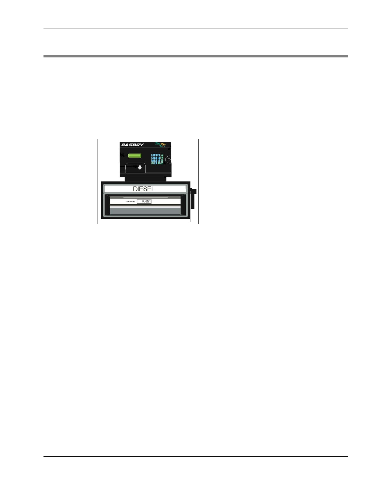
The Gasboy TopKAT is a microprocessor-based fuel control and data acquisition system,
mounted on top of a 9800 pump/dispenser or on a pedestal with the 9820 ASTRA
mechanical pump/dispenser, that is designed to gather and record specific information about
your fuel management operation as well as provide unattended access to your fuel site.
Figure 1-1: Typical TopKAT Installation
Introduction
®
or
Access to the system is controlled by vehicle code keypad entry (also called keyless entry) or
by special data keys that relate to vehicle file records maintained on the system. There are six
possible key types available:
• Vehicle: Key type 0. Linked to the vehicle that will be fueling and the department to
which it belongs. This is the most common key for accessing fuel.
• Supervisor: Key type 3. Provides access for fueling by a supervisor manually entering a
key number or a vehicle number and department number.
• Manager: Key type 8. Provides access to system configuration and setup functions,
utilities and diagnostics, and reports.
• Report*: Key type 9. Provides access to report printing capabilities, while restricting
access to other manager functions.
• Dipstick*: Key type 5. Allows dipstick readings to be entered at the TopKAT keypad.
• Delivery*: Key type 4. Allows delivery transactions to be entered at the TopKAT keypad.
* Available for use at standalone TopKAT or TopKAT master unit.
MDE-4338A TopKAT™ Fuel Management System Operation Manual · February 2009 Page 1
Page 10

Introduction Abbreviations and Acronyms
There are six possible system configurations for the TopKAT:
• Standalone electronic: one TopKAT up to eight electronic hoses
• Standalone mechanical: one TopKAT, one or two mechanical hoses
• Standalone or master/satellite controlling up to eight mechanical hoses (four hoses per
PCU, up to two PCUs). This option is referred to as Mechanical PCU in this manual.
• Master/Satellite, all electronic: Up to eight electronic hoses; one TopKAT acts as the
master and controls all hoses. It also allows up to seven satellite readers which can access
all pumps.
• Master/Satellite, all mechanical, up to 16 hoses; (two hoses per TopKAT)
• Master Satellite, one 9820 or 9800 single or twin, electronic controlled by the master. Up
to 14 mechanical hoses (two hoses per TopKAT) controlled by the satellites.
Abbreviations and Acronyms
Term Description
&F load a read-only factory configuration (a modem command to not be used)
&V display current configuration (a modem command to not be used)
AC Alternating Current
ARP Address Resolution Protocol
ASC Authorized Service Contractor
ASCII American Standard Code for Information Interchange
ATR go off hook (a modem command to not be used)
C
CD Carrier Detect
COMM Communications
CPU Central Processing Unit
CRC Cyclical Redundancy Check (as in CRC1 or CRC2)
CRT Cathode Ray Tube
DC Direct Current
DD (or dd) Day of month (01 - 31)
DIP Dual Inline Package
E1 modem displays keyboard commands (a modem command to not be used)
EIA Electronic Industries Alliance (formerly Electronic Industries Association)
EPROM Erasable Programmable Read-Only Memory
F
HPG Hours Per Gallon
HPL Hours Per Liter
I/F Interface
ID Identification
IEEE Institute of Electrical & Electronics Engineers
IP Internet Protocol
K Kilo or One Thousand (as in 64K, 128K, or 256K)
KM/L Kilometers Per Liter
Celsius (as in 0°C)
Fahrenheit (as in 32°F)
Page 2 MDE-4338A TopKAT™ Fuel Management System Operation Manual · February 2009
Page 11

Abbreviations and Acronyms Introduction
Term Description
L/100KM Liters Per 100 Kilometers
LAN Local Area Network
LCD Liquid Crystal Display
LED Light Emitting Diode
LPH Liters Per Hour
MAC Machine Address Code (also known as Hardware or Ethernet address)
MM (or mm) Month (01 - 12)
Modem Modulator-Demodulator
MPG Miles Per Gallon
N/A Non Applicable
P/N Part Number
PBX Private Branch Exchange
PC Personal Computer
PCB Printed Circuit Board
PCMCIA Peripheral Component Micro Channel Interconnect Architecture
PCU Pump Control Unit
PIN Personal Identification Number
POS Point Of Sale
Q0 displays result codes (a modem command)
Q1 quiet mode, no result codes display (a modem command)
QTY Quantity
RAM Random Access Memory
RDY Ready
ROM Read-Only Memory
RS Recommended Standard of IEEE (as in RS-232 or RS-422)
SNMP Simple Network Management Protocol
SRAM Static Random Access Memory
SW Switch
T/Net TopKAT Network
TCP Transmission Control Protocol
TFTP Trivial File Transfer Protocol
TP Test Point (as in TP1, TP2, and so on)
TPI Transport Service Programmers Interface
TTY Teletypewriter
V Version (as in V1.0, V1.1, or V2.0)
Volt or Volts (as in 5V DC)
VEH Vehicle
VPP (or Vpp) programable power supply
VR Variable Resistor
WP Write Protect
YY (or yy) Year, last two digits (00 - 99)
MDE-4338A TopKAT™ Fuel Management System Operation Manual · February 2009 Page 3
Page 12

Introduction Warranty
Warranty
For information on warranty, refer to MDE-4255 Gasboy’s Warranty Policy Statement. If you
have any warranty-related questions, contact Gasboy’s Warranty Department at its
Greensboro location.
Page 4 MDE-4338A TopKAT™ Fuel Management System Operation Manual · February 2009
Page 13
2 – Important Safety Information
Important Safety Information
This section introduces the hazards and safety precautions
associated with installing, inspecting, maintaining or servicing
this product. Before performing any task on this product, read
this safety information and the applicable sections in this
manual, where additional hazards and safety precautions for
your task will be found. Fire, explosion, electrical shock or
pressure release could occur and cause death or serious
injury, if these safe service procedures are not followed.
Preliminary Precautions
You are working in a potentially dangerous environment of
flammable fuels, vapors, and high voltage or pressures. Only
trained or authorized individuals knowledgeable in the related
procedures should install, inspect, maintain or service this
equipment.
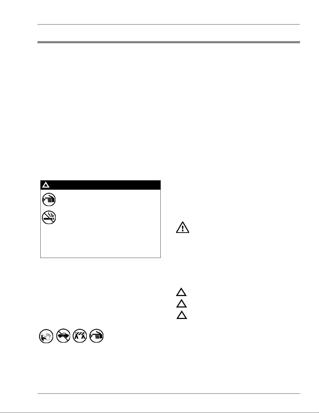
Emergency Total Electrical Shut-Off
The first and most important information you must know is
how to stop all fuel flow to the pump/dispenser and island.
Locate the switch or circuit breakers that shut off all power to
all fueling equipment, dispensing devices, and Submerged
Turbine Pumps (STPs).
!
WARNING
!
The EMERGENCY STOP, ALL STOP, and
PUMP STOP buttons at the cashier’s station
WILL NOT shut off electrical power to the pump/
dispenser. This means that even if you activate
these stops, fuel may continue to flow
uncontrolled.
Read the Manual
Read, understand and follow this manual and any other
labels or related materials supplied with this equipment. If you
do not understand a procedure, call a Gasboy Authorized
Service Contractor or call the Gasboy Service Center at 1800-444-5529. It is imperative to your safety and the safety of
others to understand the procedures before beginning work.
Follow the Regulations
Applicable information is available in National Fire Protection
Association (NFPA) 30A; Code for Motor Fuel Dispensing
Facilities and Repair Garages, NFPA 70; National Electrical
Code (NEC), Occupational Safety and Hazard Association
(OSHA) regulations and federal, state, and local codes. All
these regulations must be followed. Failure to install, inspect,
maintain or service this equipment in accordance with these
codes, regulations and standards may lead to legal citations
with penalties or affect the safe use and operation of the
equipment.
Replacement Parts
Use only genuine Gasboy replacement parts and retrofit kits
on your pump/dispenser. Using parts other than genuine
Gasboy replacement parts could create a safety hazard and
violate local regulations.
Safety Symbols and Warning Words
This section provides important information about warning
symbols and boxes.
Alert Symbol
You must use the TOTAL ELECTRICAL SHUTOFF in the case of an emergency and not the
console’s ALL STOP and PUMP STOP or
similar keys.
Total Electrical Shut-Off Before Access
Any procedure that requires access to electrical components
or the electronics of the dispenser requires total electrical
shut off of that unit. Understand the function and location of
this switch or circuit breaker before inspecting, installing,
maintaining, or servicing Gasboy equipment.
Evacuating, Barricading and Shutting Off
Any procedure that requires access to the pump/dispenser or
STPs requires the following actions:
• An evacuation of all unauthorized persons and vehicles
from the work area
• Use of safety tape, cones or barricades at the affected
unit (s)
• A total electrical shut-off of the affected unit (s)
This safety alert symbol is used in this manual and
on warning labels to alert you to a precaution which must be
followed to prevent potential personal safety hazards. Obey
safety directives that follow this symbol to avoid possible
injury or death.
Signal Words
These signal words used in this manual and on warning
labels tell you the seriousness of particular safety hazards.
The precautions below must be followed to prevent death,
injury or damage to the equipment:
DANGER: Alerts you to a hazard or unsafe practice
!
which will result in death or serious injury.
WARNING: Alerts you to a hazard or unsafe practice
!
that could result in death or serious injury.
CAUTION with Alert symbol: Designates a hazard or
!
unsafe practice which may result in minor injury.
CAUTION without Alert symbol: Designates a hazard
or unsafe practice which may result in property or
equipment damage
Working With Fuels and Electrical Energy
Prevent Explosions and Fires
Fuels and their vapors will explode or burn, if ignited. Spilled
or leaking fuels cause vapors. Even filling customer tanks will
cause potentially dangerous vapors in the vicinity of the
dispenser or island.
MDE-4338A TopKAT™ Fuel Management System Operation Manual · February 2009 Page 5
Page 14
Important Safety Information
No Open Fire
Open flames from matches, lighters, welding torches
or other sources can ignite fuels and their vapors.
No Sparks - No Smoking
Sparks from starting vehicles, starting or using power tools,
burning cigarettes, cigars or pipes can also ignite fuels and
their vapors. Static electricity, including an electrostatic
charge on your body, can cause a spark sufficient to ignite
fuel vapors. Every time you get out of a vehicle, touch the
metal of your vehicle, to discharge any electrostatic charge
before you approach the dispenser island.
Working Alone
It is highly recommended that someone who is capable of
rendering first aid be present during servicing. Familiarize
yourself with Cardiopulmonary Resuscitation (CPR) methods,
if you work with or around high voltages. This information is
available from the American Red Cross. Always advise the
station personnel about where you will be working, and
caution them not to activate power while you are working on
the equipment. Use the OSHA Lockout/ Tagout procedures. If
you are not familiar with this requirement, refer to this
information in the service manual and OSHA documentation.
Working With Electricity Safely
Ensure that you use safe and established practices in working
with electrical devices. Poorly wired devices may cause a fire,
explosion or electrical shock. Ensure that grounding
connections are properly made. Take care that sealing
devices and compounds are in place. Ensure that you do not
pinch wires when replacing covers. Follow OSHA Lockout/
Tagout requirements. Station employees and service
contractors need to understand and comply with this program
completely to ensure safety while the equipment is down.
In an Emergency
Inform Emergency Personnel
Compile the following information and inform emergency
personnel:
• Location of accident (for example, address, front/back of
building, and so on)
• Nature of accident (for example, possible heart attack, run
over by car, burns, and so on)
• Age of victim (for example, baby, teenager, middle-age,
elderly)
• Whether or not victim has received first aid (for example,
stopped bleeding by pressure, and so on)
• Whether or not a victim has vomited (for example, if
swallowed or inhaled something, and so on)
WARNING
!
Gasoline ingested may cause unconsciousness
and burns to internal organs.
Do not induce vomiting.
Keep airway open.
Oxygen may be needed at scene.
Seek medical advice immediately.
WARNING
!
Gasoline inhaled may cause unconsciousness
and burns to lips, mouth and lungs.
Keep airway open.
Seek medical advice immediately.
WARNING
!
Gasoline spilled in eyes may cause burns to eye
tissue.
Irrigate eyes with water for approximately 15
minutes.
Seek medical advice immediately.
WARNING
Hazardous Materials
Some materials present inside electronic enclosures may
present a health hazard if not handled correctly. Ensure that
you clean hands after handling equipment. Do not place any
!
Gasoline spilled on skin may cause burns.
Wash area thoroughly with clear water.
Seek medical advice immediately.
equipment in the mouth.
!
WARNING
The pump/dispenser contains a chemical known to the
State of California to cause cancer.
IMPORTANT: Oxygen may be needed at scene if gasoline
has been ingested or inhaled. Seek medical advice
immediately.
Lockout/Tagout
Lockout/Tagout covers servicing and maintenance of
WARNING
!
machines and equipment in which the unexpected
energization or start-up of the machine(s) or equipment or
The pump/dispenser contains a chemical known to the
State of California to cause birth defects or other
reproductive harm.
release of stored energy could cause injury to employees or
personnel. Lockout/Tagout applies to all mechanical,
hydraulic, chemical or other energy, but does not cover
electrical hazards. Subpart S of 29 CFR Part 1910 - Electrical
Hazards, 29 CFR Part 1910.333 contains specific Lockout/
Tagout provision for electrical hazards.
Page 6 MDE-4338A TopKAT™ Fuel Management System Operation Manual · February 2009
Page 15
Hazards and Actions
Important Safety Information
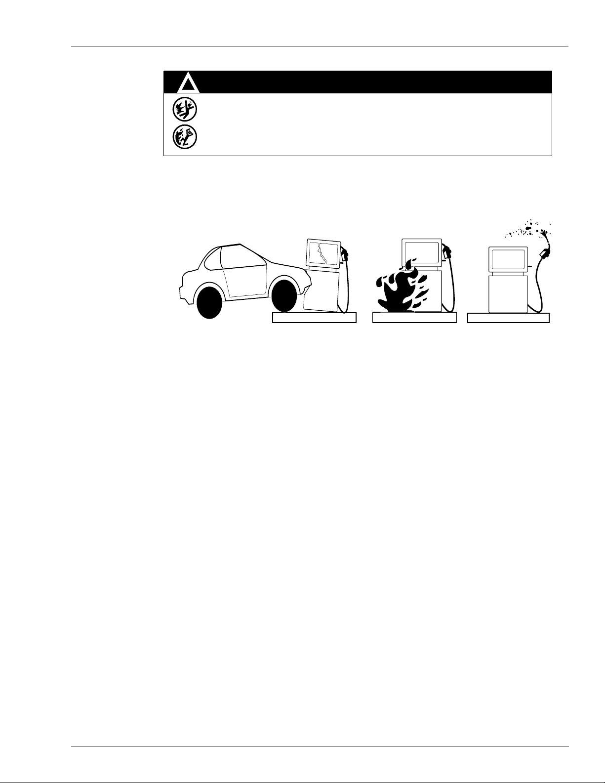
!
WARNING
Spilled fuels, accidents involving pumps/dispensers, or uncontrolled fuel flow create a
serious hazard.
Fire or explosion may result, causing serious injury or death.
Follow established emergency procedures.
The following actions are recommended regarding these hazards:
Collision of a Vehicle with Unit Fire at Island Fuel Spill
• Do not go near a fuel spill or allow anyone else in the area.
• Use station EMERGENCY CUTOFF immediately. Turn off all system circuit breakers to the
island(s).
• Do not use console E-STOP, ALL STOP and PUMP STOP to shut off power. These keys do not
remove AC power and do not always stop product flow.
• Take precautions to avoid igniting fuel. Do not allow starting of vehicles in the area. Do not allow
open flames, smoking or power tools in the area.
• Do not expose yourself to hazardous conditions such as fire, spilled fuel or exposed wiring.
• Call emergency numbers.
MDE-4338A TopKAT™ Fuel Management System Operation Manual · February 2009 Page 7
Page 16

Important Safety Information
This page is intentionally left blank.
Page 8 MDE-4338A TopKAT™ Fuel Management System Operation Manual · February 2009
Page 17

Hardware Description System Overview
3 – System Overview
Hardware Description
The TopKAT is totally self-contained in a rugged, well-designed, and attractive weatherized
cabinet. The front bezel and rear of the cabinet are hinged doors secured with locks to prohibit
unauthorized access. The front bezel allows access to the optional report printer and paper.
When installing, be sure to provide adequate clearance to allow easy access to both front and
rear doors for servicing.
The wiring for all equipment connected to the TopKAT is terminated in the head. A
standalone TopKAT can control up to eight electronic hoses or two mechanical hoses. If you
have the master/satellite option, you can control up to eight electronic hoses and seven satellite
readers or up to 16 mechanical (two hoses per TopKAT), or one 9820 or 9800 single or twin
electronic and up to 14 mechanical hoses (two hoses per TopKAT). A standalone or master/
satellite with the mechanical PCU option can control up to eight mechanical hoses (four hoses
per PCU, up to two PCUs). The system can handle quantity pulsing rates of 1000 pulses per
unit of product.
The unit is equipped with a data key receptacle. Visual prompting messages, displayed on the
two-line Liquid Crystal Display (LCD), guide the user through the steps required to activate
the pump/remote dispenser, as well as configure the system. The display is backlit so that it
can be read at night. A 16-position non-tactile keypad is provided on the face of the unit for
entering data such as Personal Identification Number (PIN), odometer reading, pump
selection, and so on. A beeper indicates when a key is pressed.
Power: AC power for the TopKAT comes from the same power connection used to power the
9800 Micro Feed. No customer connections are required between the 9800 and TopKAT.
Connections to the 9820 are made as detailed in MDE-4319 TopKAT Fuel Management
System Installation Manual.
Operating Environment: The unit has been designed to withstand an environment of -22
°
F (-30°C to 50°C), 95% relative humidity, non-condensing.
122
Location: The TopKAT is located on the fueling island. Adequate clearance around the head
of the unit is important to provide room for maintenance of the system. A minimum of 14
inches of clearance from the rear of the unit must be provided to allow the rear door to open.
°
F to
MDE-4338A TopKAT™ Fuel Management System Operation Manual · February 2009 Page 9
Page 18
System Overview CPU Printed Circuit Board
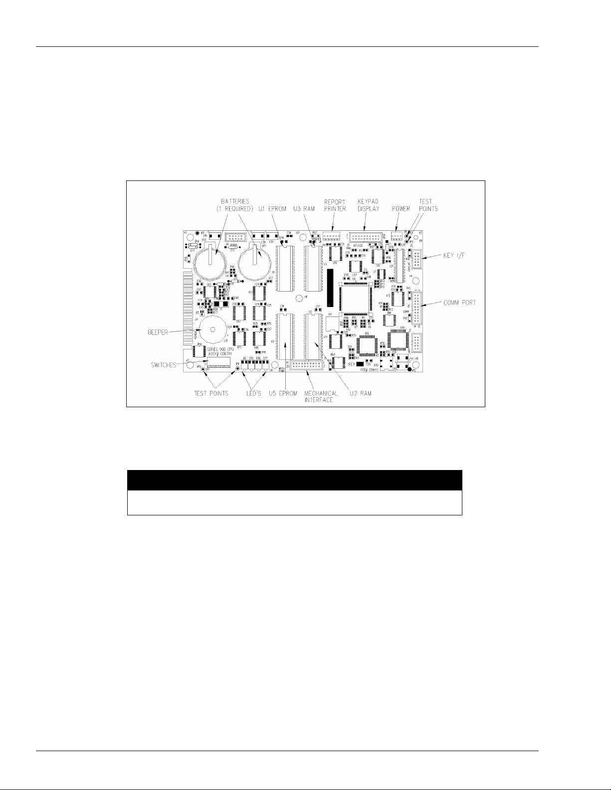
CPU Printed Circuit Board
The Central Processing Unit (CPU) Printed Circuit Board (PCB) and its relevant components
are shown in Figure 3-1.
Figure 3-1: CPU PCB Components
CPU PCB Switch Settings
CAUTION
All switch settings, except SW1-1 should be changed with the system power OFF.
• Switch settings SW1-3 through SW1-8 are read once by the CPU PCB directly after power
is turned on.
• SW1-1 is read by the CPU periodically during normal operation.
• When setting switches, open=up; closed=down.
Page 10 MDE-4338A TopKAT™ Fuel Management System Operation Manual · February 2009
Page 19

CPU Printed Circuit Board System Overview
The CPU PCB switches should be set as follows:
Switch Function Setting
SW1-1 Manager Mode Open
Normal Operation Closed
SW1-2 Not used
SW1-3 Report Printer Enabled Open
Report Printer Disabled Closed
SW1-4 Internal Modem Enabled Open
Internal Modem Disabled Closed
Port 2 Baud Rate SW1-5 SW1-6
300 Closed Closed
1200 Closed Open
2400 Open Closed
9600 Open Open
CPU LEDs
Port 3 Baud Rate SW1-7 SW1-8
300 Closed Closed
1200 Closed Open
2400 Open Closed
9600 Open Open
The purpose of the CPU LEDs (left to right) is as follows:
LED Color Indicates
D9 Yellow System Health: should flash approximately 2 times per second
D15 Green Power On
D16 Amber Battery Low
D17 Red CPU PCB Reset Active
MDE-4338A TopKAT™ Fuel Management System Operation Manual · February 2009 Page 11
Page 20

System Overview Communications
Battery Maintenance/Replacement
Check Battery Low LED periodically. If lit, replace the battery using the following procedure.
CAUTION
Do not turn off system power! This could cause irrevocable loss of data.
1 Insert a new battery, C09415, into the empty battery receptacle on the CPU PCB.
2 Remove the old battery from its battery receptacle. Battery Low (Amber) LED should go out.
Communications
Communications Ports
The TopKAT contains three asynchronous ports:
• Port 1 is used for communications to the 9800, mechanical PCU, and satellites via RS-485
lines.
• Ports 2 and 3 can be set for either RS-232 or RS-422 communications to a data terminal or
computer. If used with the 9800, wiring restrictions dictate that only one of these two ports
can be used for terminal/computer communication, unless Port 3 is connected to an
internal modem. The 9820 ASTRA and the mechanical PCU option have no wiring
restrictions.
MDE-4340/MDE-4341 Series 9800 Q/A Installation/Operation Manual, MDE-4319 TopKAT
Installation Manual, MDE-4331 Atlas
Enhanced Communications Installation Manual contain detailed communication requirements
for port wiring and exceptions. Communication is through direct wire, by dial-up phone lines
using an optional internal modem, by serial-to-LAN connection, or wireless communications.
Communications Protocol
Devices that communicate with the TopKAT must be able to transmit and receive full duplex,
ASCII asynchronous data via an EIA RS-232 connection.
The TopKAT supports both a simple and a structured computer protocol. With the simple
terminal protocol, no special characters are transmitted to designate the beginning or end of
data blocks. Data is transmitted in serial bit format per character as follows: one start bit, eight
data bits, one stop bit. Each character is echoed back to the transmitting device. This checks
the integrity and enables the CRT operators to display transmitted data.
The structured computer protocol is covered in a separate manual, C35965 TopKAT Host
Communications Manual.
™
Fuel Systems Installation Manual, and MDE-4520
Page 12 MDE-4338A TopKAT™ Fuel Management System Operation Manual · February 2009
Page 21

Communications System Overview
Initiating Communications
You can communicate with the TopKAT by one of the following methods:
• Via the LCD menu system using SW1-1 Manager Mode switch
• Via the LCD menu system using the Manager’s key
• Via terminal commands using a data terminal or PC
During initial power-up, you must use the Manager Mode switch which is located on the CPU
Board. Setting DIP switch (SW1-1) to the Open position places the system in Manager mode
and activates the LCD Menu System. The system displays COMMAND: SETUP.
You can access the LCD menu system using the Manager key any time after the System ID,
Password, and Vehicle Record for the Manager Key are entered into the Database.
You can access the TopKAT command mode via a data terminal or PC for the first time by
setting the Manager Mode switch (SW1-1) to OPEN and entering terminal commands (no
password is required). Later, when the switch is in its normally closed position, you can access
the commands by entering the correct password at the SIGN ON: prompt then entering
terminal commands. This ensures system security.
Operating Modes
There are two modes of operation, direct printout mode and command mode. In direct printout
mode, the TopKAT displays transactions and system events on the data terminal (or logger) as
they occur.
Note: The Configure Logger command (CO LOG) must be set to enabled for this to occur.
In command mode, you enter terminal commands to input data, change data, or print reports
on the system. When you are in command mode, transactions do not print as they occur,
instead they are stored in memory and printed when the system returns to direct printout mode.
Note: When you sign on in command mode, the system automatically signs off after 5 minutes
of keyboard inactivity and returns the system to direct printout mode.
9800 Switch Settings
The table below contains the proper switch /jumper settings for the 9800 CPU PCB for
operation with the TopKAT. Refer to MDE-4334 Atlas
additional information on setting 9800 switches/jumpers.
Switch SW1/Jumper Function Setting
Old CPU
SW1-1 JP1 9600 Baud Open
SW1-2 JP2 On-Line Mode Open
SW1-3/SW1-4 JP3/JP4 Delay Time Setting
SW1-5 JP5 Not used N/A
SW1-6 JP6 No Authorization Open
SW1-7 JP7 Reset Totalizers Closed
New CPU
(M06333KXXXX)
™
Start-up/Service Manual for
0 seconds Closed/Closed
4 seconds Closed/Open
5 seconds Open/Closed
6 seconds Open/Open
Normal Open
MDE-4338A TopKAT™ Fuel Management System Operation Manual · February 2009 Page 13
Page 22

System Overview Communications
Switch SW1/Jumper Function Setting
New CPU
Old CPU
SW1-8 JP8 RS-485 Pump Stop Detection
N/A JP9 Not used N/A
(M06333KXXXX)
Closed
Disabled
JP3 and JP4 set the delay time used by leak detectors in submersible pump applications. The
delay time is the period between activation of the submersible pump and activation of the slow
flow valve. Set this time according to the type of leak detector installed on the submersible
pump to allow a normal leak test for each transaction. The delay time should be set to 0
seconds for suction pumps.
JP7 should be open for normal operation. When closed, this switch enables the reset of
electronic totalizers.
JP8 is available only with 9800 software, version 5.3 or higher. Switch 1-8 is set to Closed to
disable RS485 pump stop detection. This is necessary because the TopKAT operates in a halfduplex configuration and it is possible for the 98xx to detect a false break character when the
half duplex lines switch from receive mode to transmit mode and vice-versa. These random
false break characters will cause the 98xx to terminate the transaction.
SW2-1 through SW2-4
(Only on M06333KXXXX CPU)
Function Setting
Address 1 All Closed
SW2-5 and SW2-6 - Unit of Measure Selection
(Only on M06333KXXXX CPU)
These two switches set the unit of measure (US gallons, liters, or Imperial gallons) that the
pump/dispenser will be using to meter fuel.
Unit of Measure SW2-5 SW2-6
US Gallons Closed Closed
Liters Open Closed
Imperial Gallons Closed Open
NOT USED (default US Gallons) Open Open
SW2-7 - Electro-mechanical Totalizer Enable
(Only on M06333KXXXX CPU)
This switch is only used on K model dispensers/pumps (excluding the 9850K model). When
closed (“On”), it enables the pump/dispenser to drive electro-mechanical totalizers used on
some K pump models. On A and Q models, this switch is ignored.
EM Totalizer SW2-7
Enabled Closed
Disabled Open
Page 14 MDE-4338A TopKAT™ Fuel Management System Operation Manual · February 2009
Page 23
Report Printer Interface Option - Standalone or Master Only System Overview
SW2-8 - Background Debug Module (BDM) Enable
(Only on M06333KXXXX CPU)
This switch must be OPEN for normal operation.
SW2-9 - Software Load Enable
(Only on M06333KXXXX CPU)
This switch must be OPEN for normal operation. When this switch is closed, it enables
loading the new M06333KXXXX CPU software.
SW2-10
(Only on M06333KXXXX CPU)
This switch is not used. Set to the Open position.
Report Printer Interface Option - Standalone or Master Only
A report printer interface is available as an option for the TopKAT. TopKAT is equipped with
a report printer have a printer controller board and a print mechanism mounted in the lower
right-hand side of the bezel. Printer output exits the base of the bezel through a weatherprotection printer door. This door should remain closed except while printing reports. The
system prompts you to open the printer door before printing reports. The report printer option
is available only at a standalone or master TopKAT unit.
Accessing the Printer
To access the printer, insert the key into the key slot located at the right-hand side of the bezel.
Turn it clockwise, then pull outward to open the bezel.
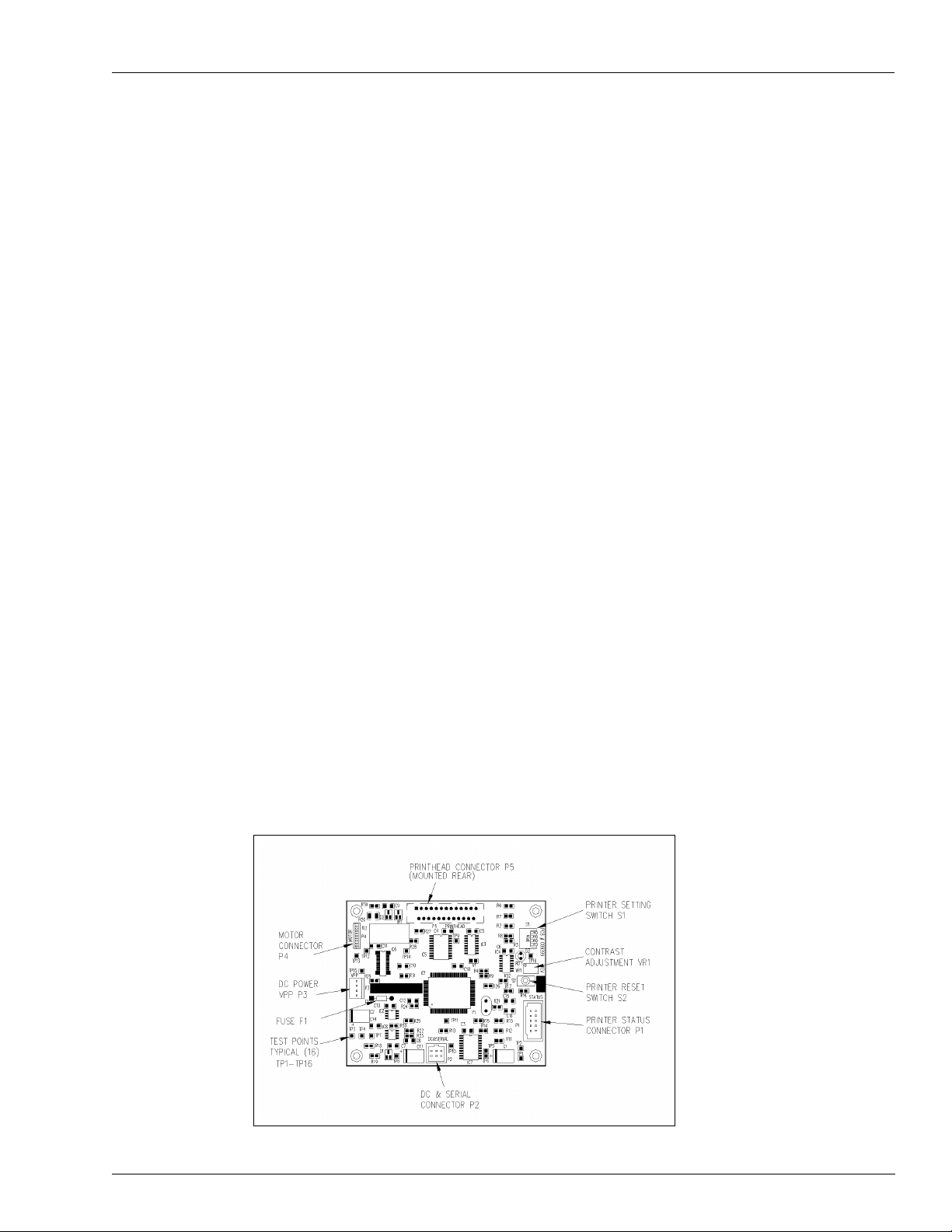
Printer Controller PCB
Figure 3-2: Printer Controller PCB Components
MDE-4338A TopKAT™ Fuel Management System Operation Manual · February 2009 Page 15
Page 24

System Overview Report Printer Interface Option - Standalone or Master Only
Setting Switches
Setting switches on the Printer Controller PCB can be done with the power ON. When the
required switch settings are made, press S2 Reset on the Printer Controller PCB and the
system will read the new settings. The RDY light on the Printer Controller PCB indicates that
the printer is online and ready to print. If the printer does not print, press Reset and verify that
the RDY light comes on.
Your switches should be set properly at the factory; however, you can verify their settings as
follows:
Switch SW1 Function Setting
SW1-1 Not used N/A
SW1-2 Paper Thickness: 1-ply Open (factory setting)
Paper Thickness: 2-ply Closed
SW1-3, SW1-4 Head Rank: A Open, Open
Head Rank: B Open, Closed
Head Rank: C Closed, Open
SW1-3 and SW1-4 indicate print head resistance. The settings for SW1-3 and SW1-4 must
correspond to the head rank (A, B, or C) indicated on the label on the top left of the printer
mechanism.
Adjusting Contrast
If contrast adjustment is necessary, adjust VR1 on the Printer Controller PCB. It is set to mid
range at the factory. Adjusting the print contrast to darker will slow the print speed; adjusting
the print contrast lighter will increase the print speed.
Page 16 MDE-4338A TopKAT™ Fuel Management System Operation Manual · February 2009
Page 25
Report Printer Interface Option - Standalone or Master Only System Overview
Loading Paper
When printer paper is getting low, a pink band will appear on the edge of the paper.
Replacement paper is available from Gasboy, P/N C01819. Follow these steps to replace the
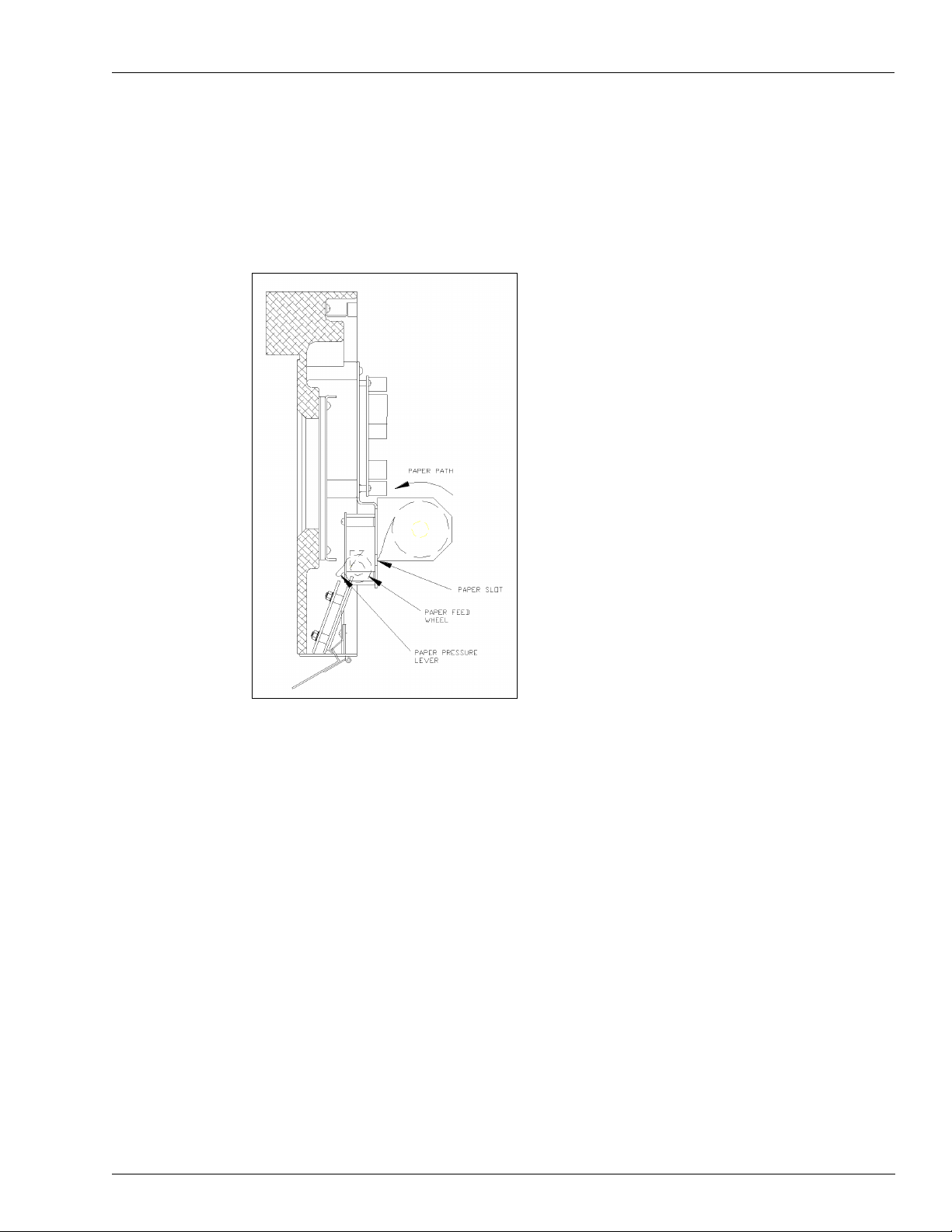
paper and see
Figure 3-3: Printer - Side View
Figure 3-3.
1 To access the printer, insert the key into the key slot located at the right-hand side of the bezel.
Turn it clockwise, then pull outward to open the bezel.
2 Looking at the rear side of the bezel, locate the printer paper holder and printhead mechanism.
At the right-hand side of the printhead, locate the printhead paper feed wheel.
3 Turn the paper feed wheel counterclockwise until the paper is removed.
Note: If the paper does not move when the paper feed wheel is rotated, the paper pressure
lever is in the pressure release position. Rotate the lever toward you so that it points
straight downward. This places the lever in the pressure engage position.
4 Using a flat-blade screwdriver, remove the screw and the small metal plate securing the left
side of the paper holder. Remove the old paper roll.
5 Take the new paper roll and feed the paper into the paper slot. Turn the paper feed wheel
clockwise until paper catches.
6 Install the paper roll on the spindle with the paper feeding counterclockwise, over the top of
the roll and into the slot.
MDE-4338A TopKAT™ Fuel Management System Operation Manual · February 2009 Page 17
Page 26
System Overview PCMCIA Interface Option - Standalone or Master Only
7 Reattach small metal plate and screw.
8 Press S2 Reset on the printer controller board to put the printer back online. The RDY light
should go on.
9 Close bezel and lock turning the key counterclockwise and pressing the bezel inward until
locked.
PCMCIA Interface Option - Standalone or Master Only
An optional Peripheral Component Micro Channel Interconnect Architecture (PCMCIA)
interface allows a user to back up and restore all or part of the system’s memory which
includes the vehicle and employee file data, transactions, and system configuration.
The PCMCIA option consists of a PCMCIA interface board with a socket for insertion of a
PCMCIA card. The PCMCIA socket/board is accessible through the back door of the cabinet.
User prompts at the display guide the user through the backup or restore process.
The PCMCIA option is available only at a standalone or master TopKAT unit.
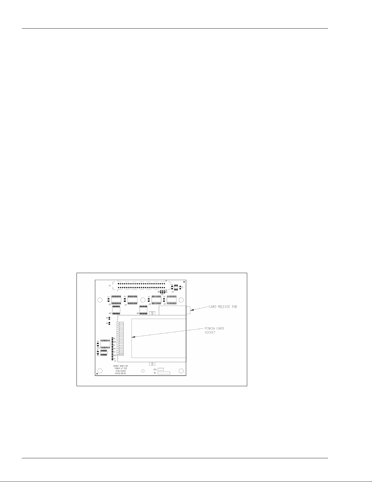
PCMCIA Interface PCB
Figure 3-4: PCMCIA Interface PCB Components
Page 18 MDE-4338A TopKAT™ Fuel Management System Operation Manual · February 2009
Page 27

Master/Satellite (T/Net) Option System Overview
Master/Satellite (T/Net) Option
The master/satellite option (also called the T/Net option), allows you to network up to 8
TopKAT units together to control a maximum of 16 hoses (electronic and mechanical
combination). If all your pumps are 9800 electronic pumps or you have mechanical PCUs, up
to 8 hoses may be controlled. One TopKAT functions as the master unit, the remaining units
function as satellites. A single database resides at the master consisting of system data, vehicle
file data, manual entry file data, transaction, pump, and tank data.
The master TopKAT provides the satellite with the vehicle and (if configured) the manual
entry records required to authorize a transaction. If your configuration is all 9800 electronics
or uses mechanical PCUs, the TopKAT master controls all pumps. If you are using a
combination of 9800 electronic and mechanical pumps, the master controls the electronic
pump (one PCU, single or twin pump) and the satellite controls its local mechanical pump(s)
and returns completed transaction data to the master upon completion of a sale. The master
TopKAT then updates its database with transaction information.
The TopKAT with the master/satellite option is set up and configured slightly differently from
a standalone TopKAT. The differences are as follows:
• Load Mode (refer to “Setup Menu” on page 30)
This new prompt is present in all TopKAT units. When your TopKAT is a standalone
unit, this prompt is set to standalone. When using the master/satellite option, the master
unit is designated as Master. This prompt must be set to Satellite at each satellite unit.
• Poll Address (refer to “Setup Menu” on page 30)
Functions the same as for standalone TopKAT units; however the master must be set as 01
and the satellites must be set as 01 through 07.
• Password (refer to “Setup Menu” on page 30)
Can be loaded at master and at satellites.
• Config Trans File (refer to “Transaction File Setup - Keypad” on page 55)
All functions available at master unit; only Clear Trans in Progress, available at satellite
unit.
• Satellites controlling mechanical pumps are recognized as individual Pump Control Units
(PCUs) and are configured at the TopKAT master, using the PCU SETUP keypad
sequence (refer to
CONFIGURE SYSTEM and CONFIGURE PCUS terminal commands (refer to
“Terminal Commands” on page 87).
• Diagnostics are available at the keypad of both the master and satellite units; however, the
system must be stopped or the satellite must be offline. Enhanced diagnostics from the
terminal are effective only for the master unit.
• Certain options, such as PCMCIA backup and restore and report printing are available
only at the master unit.
“Tank, Pump, and PCU File Setup - Keypad” on page 47) and/or the
MDE-4338A TopKAT™ Fuel Management System Operation Manual · February 2009 Page 19
Page 28

System Overview Mechanical Interface Option
Mechanical Interface Option
The mechanical interface option (Mechanical I/F) allows the TopKAT to control and monitor
up to two mechanical pumps. TopKATs equipped with the mechanical interface can also be
used as part of a master/satellite configuration. Use of this interface results in additional
hardware (Pump Control PCB and solid-state relays) and additional software parameters.
Hardware
The Pump Control PCB is mounted on the inside rear of the chassis; solid state relays which
control power to the pump are located within the chassis. The Pump Control PCB controls all
mechanical pumps by driving the relays which control the pump power, monitors status of the
pump handle to turn relays off, monitors incoming pulses to count quantity, and contains
status LEDs and manual override switches for each hose outlet. Wiring connections and
switch settings for the Pump Control PCB are discussed in more detail in the Installation
Manual.
Software
When a mechanical interface-equipped TopKAT is used as part of a master/satellite
configuration, the TopKAT is configured using PCU assignments (refer to
File” on page 52). When used in standalone mode (one TopKAT controlling two mechanical
hoses), two parameters in the Pump File are used with the mechanical interface option: pump
switch timer and pulse rate. The parameters are loaded via the keypad under LOAD PUMP
TABLE in the Pump file or via the terminal using the L PU (LOAD PUMP) command.
“About the PCU
Pump Switch Timer Parameter
The pump switch timer parameter prevents new fueling transactions at a pump when the
handle has been left on from a previous transaction. In this case, when a new transaction is
initiated, the pump cannot reset and, if pumping is allowed, the quantity shown at the pump
includes the previous transaction quantity.
When the pump switch timer parameter is set, the handle is checked at the beginning of each
transaction. If it is found to be on, the user will see the message TURN OFF PUMP HANDLE
and the transaction will be terminated. A transaction is generated with the message PUMP
SWITCH ERROR. The user must turn off the pump handle and begin a new transaction in
order to fuel.
The pump switch timer parameter sets a time period during which the pump is checked. This
time period must be less than the time that it takes for your pump to reset and transmit a switch
detect signal back to the fuel management system. Nearly all pumps take more than one
second to reset and transmit switch detect, so the values for this option range from .1 to 1
second, in tenths of a second, with .5 being a commonly used value. This value may need to be
adjusted for your pumps. A setting of zero disables this option.
Page 20 MDE-4338A TopKAT™ Fuel Management System Operation Manual · February 2009
Page 29

Mechanical PCU Option System Overview
Pulse Rate Parameter
Set the pulse rate parameter with the appropriate pulse rate for your pump. The mechanical
interface supports pulse rates of 1, 10, 100, 500, and 1000 in gallons; 1, 10, 100, and 250 in
liters. If using a 9800 as a mechanical pump, pulsing should be set to 1000:1 for gallons; 250:1
for liters. If using bulk fueling, the pulse rates for gallons will be 1:1, 10:1 and 100:1 for
gallons and those listed above for liters.
Transaction Changes
If you have the mechanical interface option, the transaction quantity decimal places are
truncated to match the pulse rate (that is 10:1 pulse rate would display xxxxx.x; 100:1 pulse
rate would display xxxxx.xx, and so on).
Mechanical PCU Option
The Mechanical Pump Control Unit (Mechanical PCU) option for the TopKAT allows the unit
to control fueling and gather information from up to eight mechanical hose outlets (four per
PCU, with a maximum of two PCUs). The TopKAT with Mechanical PCU is mounted on top
of a pedestal. All PCUs can be mounted within the pedestal or wall-mounted. All pump/
dispenser wiring connections are made within the TopKAT pedestal, when using internal
PCUs or within the wall-mounted PCUs. The TopKAT with the Mechanical PCU option can
also be used in a master/satellite configuration. Use of this interface results in additional
hardware and software parameters.
Hardware
Software
Each mechanical PCU includes two solid-state relays and one manual override switch per hose
outlet which control power to the fuel dispensing equipment. The TopKAT can handle
quantity pulsing rates as listed below in the Pulse Rate Parameter section. Wiring connections
and switch settings for the Pump Control PCB are discussed in more detail in the Installation
Manual.
When used with the Mechanical PCU option in standalone mode or master/satellite (one
TopKAT controlling up to eight hoses on two mechanical PCUs), two parameters in the Pump
File are used: pump switch timer and pulse rate. The parameters are loaded via the keypad
under LOAD PUMP TABLE in the Pump file or through the terminal using the L PU (LOAD
PUMP) command.
Pump Switch Timer Parameter
The pump switch timer parameter prevents new fueling transactions at a pump when the
handle has been left on from a previous transaction. In this case, when a new transaction is
initiated, the pump cannot reset and, if pumping is allowed, the quantity shown at the pump
includes the previous transaction quantity.
MDE-4338A TopKAT™ Fuel Management System Operation Manual · February 2009 Page 21
Page 30

System Overview Typical Fueling Sequence - Standalone or Master/Satellite
When the pump switch timer parameter is set, the handle is checked at the beginning of each
transaction. If it is found to be on, the user will see the message TURN OFF PUMP HANDLE
and the transaction will be terminated. A transaction is generated with the message PUMP
SWITCH ERROR. The user must turn off the pump handle and begin a new transaction in
order to fuel.
The pump switch timer parameter sets a time period during which the pump is checked. This
time period must be less than the time that it takes for your pump to reset and transmit a switch
detect signal back to the fuel management system. Nearly all pumps take more than one
second to reset and transmit switch detect, so the values for this option range from .1 to 1
second, in tenths of a second, with .5 being a commonly used value. This value may need to be
adjusted for your pumps. A setting of zero disables this option.
Pulse Rate Parameter
Set the pulse rate parameter with the appropriate pulse rate for your pump. The mechanical
interface supports pulse rates of 1, 10, 100, 500, and 1000 in gallons; 1, 10, 100, and 250 in
liters. If using a 9800 as a mechanical pump, pulsing should be set to 1000:1 for gallons; 250:1
for liters. If using bulk fueling, the pulse rates for gallons will be 1:1, 10:1 and 100:1 for
gallons and those listed above for liters.
Transaction Changes
If you have the mechanical interface option, the transaction quantity decimal places are
truncated to match the pulse rate (that is, 10:1 pulse rate would display xxxxx.x; 100:1 pulse
rate would display xxxxx.xx, and so on).
Typical Fueling Sequence - Standalone or Master/Satellite
A typical fueling using a TopKAT vehicle key is accomplished as follows.
1 Position your vehicle adjacent to the fuel dispensing equipment. Be sure to note the odometer
reading (if your system requires you to enter the odometer reading).
2 In its idle state, the TopKAT LCD displays one of the following three messages:
• INSERT KEY
• ENTER VEHICLE CODE
• INSERT KEY OR ENTER VEHICLE CODE
Note: If system is stopped, OUT OF SERVICE displays on master and all satellites.
3 Insert the vehicle key into the key receptacle and turn it clockwise, or enter vehicle code* (if
not using keys). *Vehicle code is key number.
Note: If your daily limit has been exceeded, the message DAILY LIMIT EXCEEDED displays
and fueling is denied.
4 If your key requires an odometer entry, proceed to step 5. If your key requires a Manual Entry
only, skip to step 6. If your key requires a PIN entry only, skip to step 7. If your key requires
neither, skip to step 8.
Page 22 MDE-4338A TopKAT™ Fuel Management System Operation Manual · February 2009
Page 31

Typical Fueling Sequence - Standalone or Master/Satellite System Overview
5 If you are required to enter an odometer reading, the LCD displays: ENTER ODOMETER.
Use the keypad to enter the mileage that appears on your vehicle’s odometer (up to six digits,
no tenths). The digits appear as they are entered. If you make a mistake, press CLEAR and
enter the reading again. When you enter the correct reading, press ENTER. The system
performs a reasonability check and if the reading is accepted, it writes the value to the key
(into the last odometer field). If the entered odometer is not accepted, you can retry entry up to
the number of times specified in the LOAD ODOMETER RETRIES command.
6 If your system requires a manual entry, the LCD displays the prompt for that field. Enter the
data requested using the keypad. The digits appear as they are entered. If you make a mistake,
press CLEAR and reenter the data. When you enter the correct data, press ENTER.
7 If you are required to enter a PIN, the LCD displays: ENTER PIN.
Using the keypad, enter your PIN number and press ENTER. To ensure security, an asterisk
(*) appears for each digit that you press. If you make a mistake while entering your PIN, press
CLEAR and enter it again.
You have three tries to enter the correct PIN. If you have a key system, after the third
unsuccessful try, the display instructs you to TURN KEY LEFT, REMOVE. Turn and remove
your key, then start again at step 3. If you have a non-key system, after the third unsuccessful
try, the display returns to the configured idle message (step 2) and you must restart at step 3.
If your system uses the Auto Pin Lockout feature, the key is automatically locked out
(invalidated) after the third unsuccessful PIN entry.
8 The LCD displays SELECT PUMP. Enter the required pump number and press ENTER. If
you have only one pump, the system automatically selects it and does not prompt.
If the pump you selected cannot be accessed, one of the following messages appears:
• INVALID PUMP
• PUMP IN USE
• PUMP DISABLED
• INVALID FUEL
You have three tries to select a correct pump. If after three attempts, you have not chosen a
correct pump, the display for a key system instructs you to TURN KEY LEFT, REMOVE.
Turn and remove your key, then start again at step 3. For a non-key system, the display returns
to the configured idle message (step 2) and you must restart at step 3.
If the pump is available and you are authorized to use it, the display will show:
PUMP #xx IS READY
TURN KEY LEFT, REMOVE.
Note: Non-key systems will display the top line message only. Skip to step 10.
9 Remove the key from the receptacle. If you leave the key in the receptacle for more than five
seconds, an alarm sounds to remind you to remove it.
MDE-4338A TopKAT™ Fuel Management System Operation Manual · February 2009 Page 23
Page 32

System Overview Delivery or Dipstick Key Sequence
10 Proceed to dispense fuel. When you finish fueling your vehicle, turn off the dispenser handle
and return the nozzle to its holder. The transaction information is automatically recorded in the
system’s memory for later recall. The transaction information may also be printed on the data
terminal or logger.
Delivery or Dipstick Key Sequence
This is now available at Master and all on-line satellites. To enter into the Delivery or Dipstick
Key Sequence, proceed as follows:
1 Observe the selected idle message.
Note: In its idle state, the TopKAT LCD displays the selected idle message.
2 After completion of the delivery or to record a dipstick reading, insert the delivery or dipstick
key into the key receptacle and turn it clockwise.
The system responds ENTER TANK #.
3 Enter the appropriate tank number and press ENTER.
The system responds ENTER TANK QTY.
4 Enter the appropriate quantity and press ENTER.
The system responds QUAN. RECORDED TURN KEY LEFT, REMOVE.
5 Remove key.
Supervisor Key Sequence
To enter into the Supervisor Key Sequence, proceed as follows:
1 Observe the selected idle message.
Note: In its idle state, the TopKAT LCD displays the selected idle message.
2 Insert supervisor key into the key receptacle and turn it clockwise.
The system responds KEY #(0) or VEH # (1).
3 If you are entering a key number, press 0. The KEY # prompt appears.
~ OR ~
If you are entering a vehicle number; press 1. The VEH # prompt appears.
4 Enter the appropriate key or vehicle number and press ENTER.
At this point, the system follows its normal fueling sequence.
Page 24 MDE-4338A TopKAT™ Fuel Management System Operation Manual · February 2009
Page 33

Setting Up the System Getting Started/System Setup
4 – Getting Started/System Setup
Setting Up the System
When you first set up the TopKAT system, you will have to perform setup functions to define
your system attributes and vehicle file. There are several methods for this depending on your
system configuration. Setup can be performed from the TopKAT keypad, via a data terminal
and a set of terminal commands, the PCMCIA restore option, or through a Gasboy PC
Software package.
The procedure for setting up the TopKAT varies. With the keypad, you must progress through
a series of displayed commands and fill in the data for each. With the terminal, you can
execute commands individually. If you have a Gasboy PC/TopKAT software package, a series
of menus guides you through system configuration.
This section describes the steps required for setting up your system for the first time, and
keypad system setup sequences. Section 10 describes setting up the system using commands at
a data terminal. PC/TopKAT software is described in another manual, MDE-4490 PC/
TopKAT User’s Guide.
Navigating the Keypad
To access the keypad options, insert and turn the manager key. The PASSWORD prompt
appears. Enter the appropriate password and the COMMAND: SETUP prompt appears.
Note: The password may be overridden by setting CPU PCB switch SW1-1 to Open. The
COMMAND: SETUP prompt appears.
The keypad for the TopKAT consists of numeric keys 0-9 and the following keys:
ENTER transmits entered information to the TopKAT and allows you to select menu options.
It is also used to acknowledge and clear error or status messages.
CLEAR clears the entry.
NO/ESC is used as a no response to a verification prompt or to move to the first option in a
menu.
YES/PREV is used as a yes response to a verification prompt or to move back to the previous
menu level from a submenu.
UP and DOWN arrow keys move from one menu item to the next.
During command actions, the system sometimes displays this symbol <. When you see this
symbol at the end of a command display, you must press the ENTER key to acknowledge the
action and return to the previous selection.
MDE-4338A TopKAT™ Fuel Management System Operation Manual · February 2009 Page 25
Page 34

Getting Started/System Setup Setting Up Your System for the First Time
Setting Up Your System for the First Time
• Perform Setup commands to configure the system.
• Set up the files you will need for fuel management: vehicle file, manual entry file, tank
file, pump file, PCU setup file, and the transaction file.
The start-up commands for your system may be executed through the system keypad, through
the optional terminal interface, or via a PC/TopKAT software package. The commands
essential for system operation are listed with the proper access path for keypad or terminal
interface. PC/TopKAT software information is contained in a separate manual.
In addition you may use additional commands to customize your system to your personal
preferences. These commands are detailed in the chapters that follow.
Keypad Setup for Standalone or Master Mode
To enter into the Keypad Setup for Standalone or Master Mode, proceed as follows:
1 Enter Setup mode; move CPU board switch SW1, position 1 to Open.
2 Stop the pumps.
Sequence: Setup/Stop
3 Load the system mode (STANDALONE or MASTER).
Sequence: Setup/Load Mode/selection
4 Load the type of PCUs from this list:
• ALL 9800
• 4-HOSE MECH. PCU(S)
• 2-HOSE MECH I/F
• 9800 + MECH (master only).
Sequence: Setup/Load PCU Type/selection
5 Load the type of entry mode to be used from this list:
• KEY ONLY
• KEYPAD ONLY
• KEY OR KEYPAD
Sequence: Setup/Select Entry Mode/selection
6 Load the system date.
Sequence: Setup/Load Date
7 Determine if the validation of manually entered numbers will be required. You will complete
defining your manual entry file in steps
9 and 10. If not using manual entry, go to step 8.
Sequence: Setup/Manual Entry Config
8 Clear the Vehicle File.
Sequence: Setup/Vehicle File/Clear File
Page 26 MDE-4338A TopKAT™ Fuel Management System Operation Manual · February 2009
Page 35

Setting Up Your System for the First Time Getting Started/System Setup
9 Add the required vehicle records into the system file. Remember that keys purchased through
Gasboy will be encoded as key #1 through key #50, and then as specified. Load vehicle
records to correspond to existing key numbers.
Sequence: Setup/Vehicle File/Veh Rec Maintenance/Key#/Add Vehicle Record
Note: FOR KEYLESS: When using the vehicle code entry as the main identification method,
most users want the entered code to represent their vehicle number. In the system, the
vehicle code links to the key number in the vehicle file. Therefore, when you set up the
vehicle file for keyless entry, set the key numbers to match the vehicle numbers.
Consequently, when you are requested to enter your vehicle code, it will be the same as
entering your vehicle number.
10 If you are using manual entries, clear the Manual Entry File. If not, skip to step 12.
Sequence: Setup/Manual Entry File/Clear File
11 Add the required manual entry records into the system file.
Sequence: Setup/Manual Entry File/Man Rec Maintenance/Add Man Ent Record
12 Load the number of tanks.
Sequence: Setup/Tank File/Load # of Tanks
13 Initialize the tanks to clear delivery information.
Sequence: Setup/Tank File/Initialize File
14 Load the tank table.
Sequence: Setup/Tank File/Load Tank Table
15 Load PCU assignments (With standalone TopKATs or master/satellite with multiple PCUs
attached; for 9800 units attached to TopKAT; for master/satellite option, to identify
mechanical master/satellite units). If you are identifying satellites in a master/satellite
configuration, skip step
16.
Sequence: Setup/PCU Setup
16 Load the number of pumps.
Sequence: Setup/Pump File/Load # of Pumps
17 Initialize the pumps to clear the totalizers and the reset date.
Sequence: Setup/Pump File/Initialize File
18 Load the pump table.
Sequence: Setup/Pump File/Load Pump Table
19 Clear the transaction file.
Sequence: Setup/Config Trans File/Clear Trans File
20 Load the initial transaction number to 1.
Sequence: Setup/Config Trans File/Load Trans Number
MDE-4338A TopKAT™ Fuel Management System Operation Manual · February 2009 Page 27
Page 36

Getting Started/System Setup Setting Up Your System for the First Time
21 For systems with the terminal option on port 2, determine whether the logger option should be
enabled. It is disabled at the factory. When enabled, transactions will print to the terminal upon
completion. To change the setting of this command:
Sequence: Setup/Config Trans File/Config Trans Logger
22 Determine whether Memory Protection is required. The system is shipped with the Memory
Protection enabled, which means if transactions are not polled out of the system, the memory
could fill up and stop accepting new transactions until polling is completed. Disabling
Memory Protection means transactions may be overwritten as memory fills.
Sequence: Setup/Config Trans File/Memory Full Protect
23 Execute the RUN command to start communications between the dispensing equipment and
the TopKAT. This command is valid at the master only when used in master/satellite
combinations.
Sequence: Setup/Run
24 Exit Setup mode. Move CPU board switch SW1, position 1 to Closed.
Keypad Setup for Satellite Mode
To enter into the Keypad Setup for Satellite Mode, proceed as follows:
1 Enter Setup mode; move CPU board switch SW1, position 1 to Open.
2 Load the system mode (SATELLITE).
Sequence: Setup/Load Mode/selection
3 Load the type of entry mode to be used from this list:
• KEY ONLY
• KEYPAD ONLY
• KEY OR KEYPAD
Sequence: Setup/Select Entry Mode/selection
4 Load the Poll Address.
Sequence: Setup/Load Poll Address
5 Clear the transaction file.
Sequence: Setup/Config Trans File/Clear Trans File
6 Load the initial transaction number to 1.
Sequence: Setup/Config Trans File/Load Trans Number
7 For systems with the terminal option on port 2, determine whether the logger option should be
enabled. It is disabled at the factory. When enabled, transactions will print to the terminal upon
completion. To change the setting of this command:
Sequence: Setup/Config Trans File/Config Trans Logger
8 Determine whether Memory Protection is required. The system is shipped with the Memory
Protection enabled, which means if transactions are not polled out of the system, the memory
could fill up and stop accepting new transactions until polling is completed. Disabling
Memory Protection means transactions may be overwritten as memory fills.
Sequence: Setup/Config Trans File/Memory Full Protect
9 Exit Setup mode. Move CPU board switch SW1, position 1 to Closed.
Page 28 MDE-4338A TopKAT™ Fuel Management System Operation Manual · February 2009
Page 37

Setting Up Your System for the First Time Getting Started/System Setup
Terminal Mode Setup
To enter into the Terminal Mode Setup, proceed as follows:
1 Enter command mode. Press ENTER to bring up SIGN ON: message. The password is
factory loaded to GASBOY.
2 Stop the pumps if running. Type STOP.
3 Load the current date. Type LO DA.
4 Define your manual entry field name. Type CO MA. Select the name.
5 Clear files using clear file command. Type CL F and select option 5 to clear all files.
6 Add records to your vehicle file and manual entry file. Use AD REC V for the vehicle file; use
AD REC x for the manual entry file where x is the first character of the manual entry name.
Note: When loading vehicle records, remember that keys purchased through Gasboy will be
encoded as key #1 through key #50, and then as specified. Load vehicle records to
correspond to existing key numbers.
7 Configure system parameters. Use the CO SY and CO PC commands depending on your
configuration. Refer to the details for each command in
8 Initialize the pump and tank files. Type the initialize file command, I F and select option 3 to
“Terminal Commands” on page 87.
initialize the pump file and option 4 to initialize the tank file.
9 Load the pump and tank files. Type L PU and load the pump data, then type L TA and load
the tank data.
10 Load the starting transaction number. Type LO TR and enter the number.
11 For systems with the terminal option on port 2, determine whether the logger option should be
enabled. It is disabled at the factory. When enabled, transactions will print to the terminal upon
completion. Type the configure logger (CO LOG) command.
12 Determine whether Memory Protection is required. The system is shipped with the Memory
Protection enabled, which means if transactions are not polled out of the system, the memory
could fill up and stop accepting new transactions until polling is completed. Disabling
Memory Protection means transactions may be overwritten as memory fills. Type enable
protection command (EN PR).
13 Execute the RUN command to start communications between the dispensing equipment and
the TopKAT. Type RUN.
MDE-4338A TopKAT™ Fuel Management System Operation Manual · February 2009 Page 29
Page 38

Getting Started/System Setup Accessing the Main Menu Options
Accessing the Main Menu Options
To access the Main Menu Options, proceed as follows:
1 Insert and turn the Manager key.
2 Enter the password. The COMMAND: SETUP prompt displays.
3 Use the up and down arrow keys to scroll through the menu choices: SETUP, REPORTS,
DIAGNOSTICS, and UTILITIES.
Setup Menu
Accessing the Setup Commands
To access the Setup Commands, proceed as follows:
1 Access the Main Menu. When COMMAND: SETUP appears, press ENTER.
2 Use the up and down arrow keys to scroll through the SETUP commands. Press ENTER when
the required command is displayed.
3 Type any command input and press ENTER again.
4 Repeat steps 2 and 3 as needed. To exit from the SETUP commands, press PREV as many
times as necessary.
5 Use the up and down arrow keys to scroll through the main menu choices.
STOP (only for Master and Standalone Modes)
Use STOP to stop the fuel site. All ongoing transactions are terminated and site is stopped
until a RUN command is issued. This command is valid only from the master unit in master/
satellite combinations. When the system is stopped, OUT OF SERVICE displays on the
master and all satellite displays.
RUN (only for Master and Standalone Modes)
Use RUN to start (or re-start after a stop) the site. During initial system power-up, if all
essential system operating data is not correct, the system will not start and will have to be
started with the RUN command after the fault conditions are corrected. This command is valid
only from the master unit in master/satellite combinations.
LOAD MODE
Use LOAD MODE to select the operating mode for the TopKAT. Available choices are
STANDALONE, MASTER, or SATELLITE. This option must be set individually at the
master and at each satellite. When the mode is changed, you are prompted to confirm the
change.
Page 30 MDE-4338A TopKAT™ Fuel Management System Operation Manual · February 2009
Page 39

Setup Menu Getting Started/System Setup
LOAD PCU TYPE (only for Master and Standalone Modes)
Use LOAD PCU TYPE to load the configuration for the types of pumps you are using.
Available choices for standalone and master are: ALL 9800, 4-HOSE MECH PCU(S),
2-HOSE MECH. I/F. An additional choice appears on the master: 9800 + MECH.
SELECT ENTRY MODE
Use SELECT ENTRY MODE to indicate the ways the system will be accessed. Available
choices are: KEY ONLY, KEYPAD ONLY, KEY OR KEYPAD. This option must be set
individually at the master and at each satellite.
LOAD DATE (only for Master and Standalone Modes)
Use LOAD DATE to load the current date. The TopKAT should be factory-loaded with the
correct date, but occasionally, you may need to change it.
LOAD TIME (only for Master and Standalone Modes)
Use LOAD TIME to load the current time on 24-hour format (00:00 to 23:59). The TopKAT is
factory-loaded to Eastern time with the correct time, but occasionally, you may need to change
it.
LOAD SITE NO (only for Master and Standalone Modes)
Use LOAD SITE NO to load the four-digit site number. This number appears at the beginning
of each transaction listing and as the first four digits when you print compacted transactions.
LOAD POLL ADDRESS
Use LOAD POLL ADDRESS to load a two-digit address to be used for computer mode
communication with the TopKAT. For standalone, master and first satellite, this address
should be loaded to 1. If setting up a satellite, the poll address must be between 1 and 7. The
poll address becomes the assigned satellite number.
This entry also contains a subprompt that will enable you to default your terminal mode
password to GASBOY.
LOAD SYSTEM ID (only for Master and Standalone Modes)
Use LOAD SYSTEM ID to load the four-digit system ID. This number is unique to your
system, assigned at the factory, and is encoded onto your access keys. It guards against users
of other systems accessing your system.
LOAD PASSWORD
Use LOAD PASSWORD to load the manager key password. The password you enter when
using the manager key at the keypad is limited to four digits. It is factory-loaded as 1234. The
password you use when entering commands through a data terminal is limited to 10
alphanumeric characters. When using the master/satellite option, the password can be loaded
at the master and the satellites.
MDE-4338A TopKAT™ Fuel Management System Operation Manual · February 2009 Page 31
Page 40

Getting Started/System Setup Setup Menu
LOAD REAS RANGE (only for Master and Standalone Modes)
Use LOAD REAS RANGE to load a four-digit value for the maximum number of miles/hours
that may be traveled between fuelings for an odometer to be considered reasonable. If this
field is loaded as 0, the system does not use a maximum miles traveled range when it validates
the odometers, but it does expect the odometer entered to exceed any previous odometer entry.
LOAD ODOM RETRIES (only for Master and Standalone Modes)
Use LOAD ODOM RETRIES to load up to 2 digits for the number of times the odometer will
be re-prompted for when an incorrect odometer has been entered.
Note: When both LOAD REAS RANGE and LOAD ODOM RETRIES are set to 0, the system
will not perform a reasonable odometer check for any odometer entered. During a
fueling, when an odometer entry is detected, any entered odometer is accepted. If the
entered odometer is less than the previous odometer entry, fueling is allowed and an
ODOM RANGE ERROR is logged.
INVALID PIN LOCKOUT (only for Master and Standalone Modes)
Use INVALID PIN LOCKOUT to indicate whether the system should lock out a vehicle
record when an invalid PIN is entered. This is a YES or NO value. If this value is set to yes,
the vehicle record is locked out after the number of PIN tries (3) has been exceeded. If this
value is set to no, the system will not lock out the record if 3 invalid PIN tries are received.
SELECT FIELD NAME (only for Master and Standalone Modes)
Use SELECT FIELD NAME to select either DEPT or ACCT as the field name which is input
into the vehicle file and printed on reports. If you do not select this prompt, DEPT is the
default value.
MANUAL ENTRY CONFIG (only for Master and Standalone Modes)
Use MANUAL ENTRY CONFIG and its corresponding subentries to indicate how manual
entry is handled (refer to
At Manual Entry Name, select the name to be used for your manual entry field. Available
names are:
EMPLOYEE # JOB #
ACCOUNT # AUXILIARY #
TRIP # DRIVER #
MISC #
At MANUAL ENTRY CHECK, indicate required or not required.
• If manual entry check is required, a record must exist in the manual entry file. The entry
made by the user at the keypad must match a field in the manual entry record.
• If manual entry check is not required, the user can enter anything at the manual entry field
and it will be accepted.
“COnfigure MAnual (CO MA)” on page 91 for more information).
Page 32 MDE-4338A TopKAT™ Fuel Management System Operation Manual · February 2009
Page 41

Setup Menu Getting Started/System Setup
MEASUREMENT UNITS (only for Master and Standalone Modes)
This command allows you to indicate, for reporting and transactions, the type/format of units
of measure.
• DISTANCE provides 3 options: MILES, KILOMETERS, HOURS.
• QUANTITY provides 3 options: GALLONS, LITERS, LITRES.
• DATE FORMAT provides 3 options: MM/DD/YY, YY/MM/DD, DD/MM/YY.
• RATE allows you to indicate how you want your fuel efficiency monitored: MPG=miles
per gallon; HPG=hours per gallon; L/100KM=liters per 100 kilometers; LPH=liters per
hour; KM/L=kilometers per liter; HPL=hours per liter.
Note: When you select hours, instead of miles, kilometers, or liters, no system prompts are
changed. The system will still request ENTER ODOMETER. However, in reports (Print
System or Department/Vehicle) or print transactions, units will appear as hours.
• PUMP TIMEOUT MODE allows one of two time-out modes to be selected: USA or
INTERNATIONAL. USA allows for a maximum of 180 seconds, as required by Weights
and Measures. INTERNATIONAL allows for a maximum of 255 seconds.
BULK FUELING (only for Master and Standalone Modes)
This command allows you to indicate whether bulk fueling operations will be active at this
site. Select YES or NO accordingly.
Note: The PCU Type must be set to four-hose mechanical or two-hose mechanical to use bulk
fueling. If bulk fueling is set to Yes, All 9800 and 9800 + Mech cannot be selected as
PCU types.
MDE-4338A TopKAT™ Fuel Management System Operation Manual · February 2009 Page 33
Page 42

Getting Started/System Setup Setup Menu
This page is intentionally left blank.
Page 34 MDE-4338A TopKAT™ Fuel Management System Operation Manual · February 2009
Page 43

About the Vehicle File Vehicle File Setup - Keypad
5 – Vehicle File Setup - Keypad
About the Vehicle File
The vehicle file is where all vehicle information is defined. The vehicle file options are
presented in the order they appear on the menu; however, the first thing you will do is add
vehicle records.
All vehicle records must have a unique key number and vehicle/department number
combination. The vehicle/department number is combined by the system for sorting purposes.
You can access vehicle records by key number or by the vehicle/department number. Up to
2000 vehicle records may be stored.
In addition to each vehicle in your fleet, you must also provide a vehicle record for any special
keys you wish to encode (supervisor, manager, report, dipstick, or delivery). As with all
vehicle records, each special key record must have a unique key number and vehicle/
department combination, but you can just press ENTER through the remaining vehicle file
fields.
The vehicle file format is as follows:
Key No 5 digits (typically set to match vehicle number in keyless applications)
Vehicle No 5 digits
Dept or Acct* 4 digits
Limit 1 digit
Authorization 1 digit
Check Digit 1 digit
Lockout Status 1 digit
PIN # 4 digits
Beginning Odometer 6 digits
Last Odometer 6 digits
Total Quantity 8 digits (xxxxx.xxx)
Max Fuelings/Day 2 digits
# Fuelings Today 2 digits
# Fuelings to Date 3 digits - totalizer reset when file is initialized.
*As determined by Select Name prompt in Setup.
MDE-4338A TopKAT™ Fuel Management System Operation Manual · February 2009 Page 35
Page 44

Vehicle File Setup - Keypad Limitation Codes
Limitation Codes
Product limitation codes are one-digit codes that are used to restrict the maximum quantity of
product dispensed per transaction.
Product limitation is provided mainly as a safeguard to minimize accidental spillage. The
appropriate limitation code is loaded in the Limit field of the vehicle file. The value assigned
should be the nearest quantity greater than the vehicle’s tank size. If the user dispenses fuel to
the quantity limit of his key, the transaction automatically terminates. If the user wants
additional product, he can initiate another transaction and dispense additional product up to the
limit cutoff.
The table below shows the pre-assigned limitation codes available for use. When using bulk
fueling, use the table columns to the right regardless of whether bulk measurement is in
gallons.
Gallons Liter or Bulk
Limit Code Limit Cutoff Quantity Limit Code Limit Cutoff Quantity
05 0 20
115 1 60
220 2 80
3 25 3 100
42 4 8
5 50 5 200
6 100 6 400
7 200 7 800
8 300 8 1200
9 999 9 9999
Page 36 MDE-4338A TopKAT™ Fuel Management System Operation Manual · February 2009
Page 45

Authorization Codes Vehicle File Setup - Keypad
Authorization Codes
Authorization code is a one-digit numeric field (0 - 9) used to specify the type of fuels one
may access. You can load one of these code types into the Authorization field of the vehicle
file. The user is permitted to access only the product types represented by that code. Code 0
allows access to all fuels.
Up to 4 product codes (1 - 4) are supported. You decide which product code is associated with
each fuel type (that is, 1=unleaded, 2=super unleaded, 3=diesel, 4=kerosene).
The table below shows the pre-assigned authorization codes available for use.
Auth Code Product Codes Allowed
0 All Products
1 Product 1
2 Product 2
3 Product 3
4 Product 4
5 Product 1, 2
6 Product 1, 3
7 Product 2, 3
8 Product 1, 2, 3
9 Product 1, 3, 4
Check Digit
Check digit is a one-digit numeric field used to determine what data must be entered at the
keypad. The table below shows the available codes.
Code Required Manual Keypad Entries
*See “PIN” on page 38 for explanation of vehicle PIN.
0 No entries required
1 Odometer entry required
2 Manual entry required
3 Odometer and manual entry required
4 Vehicle PIN required*
5 Odometer and vehicle PIN required*
6 Manual entry and vehicle PIN required*
7 Odometer, manual entry, and vehicle PIN required*
MDE-4338A TopKAT™ Fuel Management System Operation Manual · February 2009 Page 37
Page 46

Vehicle File Setup - Keypad Lockout
Lockout
Lockout can be against the vehicle file (by Key # or Vehicle/dept combination) or the manual
entry file (by the manual entry field).
When a key is used for fueling, the system accesses the vehicle record and checks the lockout
status field.
• If it is set to LOCKED OUT, the transaction is denied.
• If it is ACTIVE, the transaction proceeds as follows.
The check digit is read and if a manual entry is required [and if manual entry check
(SETUP: MANUAL ENTRY CHECK) is set to REQUIRED], the manual entry file is
accessed.
• If the lockout status field in the manual entry file is set to LOCKED OUT, the
transaction is denied.
• If the lockout status field in the manual entry file is set to ACTIVE, the transaction
proceeds and the system prompts for the next entry.
PIN
PIN entry is required and validated against the manual entry PIN field if all of the following
conditions are met:
• manual entry is required by the vehicle record
• the system parameter MANUAL ENTRY CHECK is set to required
• the manual entry record PIN field is not 0000
PIN entry is required and validated against the vehicle record PIN if all the conditions under
any of the following scenarios are met:
Scenario 1: Vehicle PIN required and manual entry not required by vehicle record.
Scenario 2: Vehicle PIN required, manual entry required by vehicle record, and system
parameter MANUAL ENTRY CHECK is set to NOT REQUIRED.
Scenario 3: Vehicle PIN required, manual entry required by vehicle record, system parameter
MANUAL ENTRY CHECK is set to REQUIRED, manual entry record PIN field is 0000.
Page 38 MDE-4338A TopKAT™ Fuel Management System Operation Manual · February 2009
Page 47

Vehicle Record Maintenance Vehicle File Setup - Keypad
Vehicle Record Maintenance
To perform Vehicle Record Maintenance, proceed as follows:
1 Insert and turn the Manager key.
2 Enter the password. The COMMAND: SETUP prompt displays. Press ENTER.
3 Press either arrow key until VEHICLE FILE appears. Press ENTER.
4 At VEH REC MAINTENANCE, press ENTER.
5 At SEARCH BY, indicate how you want the vehicle file to be sorted. Use the arrow keys to
display one of two available options: SEARCH BY KEY # or SEARCH BY VEH/DEPT # or
VEH/ACCT # and press ENTER. The EDIT/VIEW VEHICLE prompt appears.
Edit/View Record
To edit or view the Record, proceed as follows:
1 At EDIT/VIEW VEHICLE, press ENTER. Depending on the method by which you elected to
sort the file, the following prompts appear. If you selected KEY #, the KEY # prompt and first
key record in the file appears. If you selected VEH/DEPT # or VEH/ACCT #, the VEHICLE #
prompt and the first vehicle record in the file appears.
2 Type a number at the keypad or use the arrow keys to scroll through the key or veh/dept and
veh/acct numbers using arrow keys until you reach the one you wish to edit/view and press
ENTER.
3 Use the arrow keys to display the vehicle record fields. If you wish to view the field, press
ENTER when the field name appears. Then press ENTER to return to the vehicle record files.
If you wish to edit the field, press ENTER, type a new value and press ENTER again. Then
resume using the arrow keys to view the rest of the fields.
Add Vehicle Record
To add Vehicle Record, proceed as follows:
1 At EDIT/VIEW VEHICLE, press the arrow key until ADD VEHICLE RECORD appears and
press ENTER.
The KEY # prompt appears.
2 Enter the appropriate information for key, vehicle and department or account, pressing
ENTER after each entry.
Note: The remainder of the vehicle record fields are set to zero and will remain so unless you
change them. If you do not wish to enter data into a field, press the down arrow key at
that field and the next prompt will display.
MDE-4338A TopKAT™ Fuel Management System Operation Manual · February 2009 Page 39
Page 48

Vehicle File Setup - Keypad Vehicle Record Maintenance
3 At LIMIT, press ENTER, type a limitation code (0 - 9) and press ENTER.
The LIMIT prompt reappears; use the down arrow key to proceed.
4 At AUTHORIZATION, press ENTER, type an authorization code (0 - 9) and press ENTER.
The AUTHORIZATION prompt reappears; use the down arrow key to proceed.
5 At CHECK DIGIT, press ENTER, type a one-digit check digit code (0 - 7) and press
ENTER. The CHECK DIGIT prompt reappears; use the down arrow key to proceed.
6 At LOCKOUT STATUS, press ENTER. Use the up and down arrow keys to toggle between
ACTIVE and LOCKED OUT. When the appropriate choice is displayed, press ENTER. Use
the down arrow to proceed.
7 At PIN, press ENTER, type a four-digit PIN and press ENTER.
The PIN prompt reappears; use the down arrow key to proceed.
8 At BEGINNING ODOMETER, press ENTER, then enter the odometer (six-digits; no tenths)
for the vehicle (if required) and press ENTER.
The BEGINNING ODOMETER prompt reappears; use the down arrow key to proceed.
9 At LAST ODOMETER, press ENTER, then enter the current vehicle odometer (six-digits; no
tenths), and press ENTER. Use the down arrow to proceed.
Note: Setting the odometer values to zero instructs the TopKAT to initialize the record using
the odometer received the first time the key is used.
10 At TOTAL QUANTITY, press ENTER. This field accumulates the quantity of all fueling
transactions for that vehicle record. This field is reset to zero when the vehicle file is
initialized. This allows you to monitor fuel usage for a given period, typically weekly,
monthly, or yearly based on how often you initialize the vehicle field. Enter 8 digits
(xxxxx.xxx). The decimal point is fixed, so enter the appropriate number of zeros to form the
correct number and press ENTER. Use the down arrow to proceed.
11 At MAX FUELINGS PER DAY, press ENTER. Type a two-digit number up to 15 for the
maximum amount of times one vehicle can fuel in a 24-hour period and press ENTER. Zero
allows unlimited fuelings. Use the down arrow to proceed.
12 At # FUELINGS TODAY, enter nothing. This field is updated in the vehicle file each time a
user completes a fueling transaction. This value is reset each night between 00:00 and 00:05,
depending on which time the key receptacle is idle (no key in receptacle). If no opportunity
exists for this value to reset, another 24-hour period will elapse before the system retries the
reset. Use the down arrow to proceed.
13 At # FUELINGS TO DATE, enter nothing. This field is updated from the beginning of the
system start-up or vehicle file initialization.
Delete Vehicle Record
Allows you to delete a vehicle record by whichever field you elected to sort the vehicle file. If
you sorted by key, the KEY prompt appears; if you sorted by vehicle/dept or vehicle/acct, the
vehicle number prompt appears, followed by the department or account prompt. The TopKAT
then asks you to verify your deletion by pressing the YES or NO key. Then, the record is
deleted.
Page 40 MDE-4338A TopKAT™ Fuel Management System Operation Manual · February 2009
Page 49

Vehicle Record Maintenance Vehicle File Setup - Keypad
Encode Key
Allows you to encode a key from vehicle file data. This option is available under the Edit/
View Vehicle Record and is activated by using the Manager Mode switch.
If encoding a key other than a vehicle key, remember that each key (supervisor, manager,
report, dipstick, or delivery) must have a corresponding vehicle record. As with all vehicle
records, each special key record must have a unique key number and vehicle/department
combination, but you can just press ENTER through the remaining vehicle file fields.
Note: Do not activate the Manager mode switch (SW1) while in the vehicle file. This will lock
the record and inhibit further access.
1 Activate the Manager Mode by turning switch SW1 to open. The COMMAND: SETUP
prompt displays. Press ENTER.
2 Press either arrow key until VEHICLE FILE appears. Press ENTER.
3 At VEH REC MAINTENANCE, press ENTER.
4 At SEARCH BY, indicate how you want the vehicle file to be sorted. Use the arrow keys to
display one of two available options: SEARCH BY KEY # or SEARCH BY VEH/DEPT # (or
VEH/ACCT) and press ENTER. The EDIT/VIEW VEHICLE prompt appears. Press ENTER.
5 If you selected KEY #, the KEY # prompt and first key record in the file appears. Type a
number at the keypad or use the arrow keys to scroll through the key numbers until you reach
the one you wish to encode and press ENTER.
If you selected VEH/DEPT # (or VEH/ACCT #), the VEHICLE # prompt and the first vehicle
record in the file appears. Use the arrow keys to scroll through the vehicle numbers. When you
reach the correct vehicle number, press ENTER. The DEPARTMENT or ACCOUNT prompt
appears. Use the arrow keys to scroll through the department/account records. When you reach
the one you wish to encode, press ENTER.
6 Use the arrow keys to display the vehicle record fields. If you wish to change a field, press
ENTER at the field name, type a new value and press ENTER again. Then resume using the
arrow keys to view the rest of the fields. The last option will be ENCODE KEY.
7 To encode the key using the data in that vehicle record, press ENTER. The system responds
SELECT KEY TYPE: VEHICLE. Use the arrow keys to select an alternate key type. Choices
are vehicle, supervisor, manager, report, dipstick, or delivery. Press ENTER when the proper
key type is displayed. The system responds INSERT KEY TO ENCODE.
8 Insert the key in the receptacle and turn. The key is encoded and the system displays
FINISHED, REMOVE KEY TURN KEY LEFT, REMOVE.
9 Ensure that you take the system out of manager mode by returning switch SW1 to the closed
position.
MDE-4338A TopKAT™ Fuel Management System Operation Manual · February 2009 Page 41
Page 50

Vehicle File Setup - Keypad Vehicle Record Maintenance
Initialize File
Use INITIALIZE FILE only at initial startup or if doing periodic reconciliations. Be sure to
print any required reports before running INITIALIZE FILE, otherwise you will end up with
reports containing initialized values.
This command copies the last odometer to the beginning odometer, clears all cumulative
quantity totalizers, resets the # of fuelings to date, and resets the initialization date to the
current date for the file.
Clear File
Use CLEAR FILE to clear all records from the vehicle file. This command erases any vehicle
records previously stored in the vehicle file; they cannot be retrieved unless you have the
PCMCIA backup option with a current backup of your vehicle file or a Gasboy PC/900
computer program with a current backup of your vehicle file. Important: On initial startup, be
sure to run this command before entering any vehicle records.
Page 42 MDE-4338A TopKAT™ Fuel Management System Operation Manual · February 2009
Page 51

About the Manual Entry File Manual Entry File Setup - Keypad
6 – Manual Entry File Setup - Keypad
About the Manual Entry File
The manual entry file is used when you include a check digit in the vehicle record requesting a
manual entry. Your manual entry field name is identified when you perform system SETUP
(refer to
Your system can be configured to check or not check manual entry (refer to “MANUAL
ENTRY CONFIG (only for Master and Standalone Modes)” on page 32 and “COnfigure
MAnual (CO MA)” on page 91). If manual entry check is required, a record must exist in the
manual entry file. The entry made by the user at the keypad must match a record in the manual
entry file. If manual entry check is not required, the user can enter anything at the manual
entry field and it will be accepted.
“Getting Started/System Setup” on page 25).
Your manual entry file contains all pertinent manual entry information in the following
format:
Field Format
Manual entry field 4 digits
Department* 4 digits
Total fuel 8 digits
# of fuelings 3 digits
Lockout Status 1 digit
PIN 4 digits
*This field remains as Department regardless of what you select in the SELECT NAME setup prompt.
The manual entry file can contain up to 4000 manual entry records. Like the vehicle file, the
manual entry file also contains a PIN field. Refer to “PIN” on page 38 for details on how the
PIN function operates.
MDE-4338A TopKAT™ Fuel Management System Operation Manual · February 2009 Page 43
Page 52

Manual Entry File Setup - Keypad Manual Entry File Maintenance
Manual Entry File Maintenance
Accessing the Manual Entry File
To access the Manual Entry File, proceed as follows:
1 Insert and turn the Manager key.
2 Enter the password. The COMMAND: SETUP prompt displays. Press ENTER.
3 Press the arrow key until MANUAL ENTRY FILE appears. Press ENTER.
4 At MAN REC MAINTENANCE, press ENTER.
The EDIT/VIEW MAN ENT prompt appears.
Edit/View Manual Entry
To edit or view Manual Entry, proceed as follows:
1 At EDIT/VIEW MAN ENT, press ENTER. Type a number at the keypad or use arrow keys to
scroll through the manual entry numbers until you reach the one you wish to edit/view and
press ENTER.
2 Use the arrow keys to display the manual entry record fields. If you wish to view the field,
press ENTER when the field name appears. Press ENTER again when finished. If you wish
to change the field, press ENTER, type a new value and press ENTER again. Then resume
using the arrow keys to view the rest of the fields.
Add Manual Entry Record
To add Manual Entry Record, proceed as follows:
1 At EDIT/VIEW MAN ENT, press the arrow key until ADD MAN ENT RECORD appears
and press ENTER.
2 Enter the appropriate information for your manual entry field and press ENTER.
3 At Dept. #, enter the four-digit department and press ENTER. Use the down arrow to proceed.
4 At LOCKOUT STATUS, press ENTER. Use the up and down arrow keys to toggle between
ACTIVE and LOCKED OUT. When the appropriate choice is displayed, press ENTER. Use
the down arrow to proceed.
5 At PIN (if used), press ENTER, type a four-digit PIN and press ENTER.
The PIN prompt reappears; use the down arrow key to proceed.
Page 44 MDE-4338A TopKAT™ Fuel Management System Operation Manual · February 2009
Page 53

Manual Entry File Maintenance Manual Entry File Setup - Keypad
6 At TOTAL QUANTITY, press ENTER. Enter eight digits (xxxxx.xxx) and press ENTER.
The decimal point is fixed, so enter the appropriate number of zeros to form the correct
number. Use the down arrow to proceed.
7 At # FUELINGS TO DATE, enter nothing. This field is updated from the beginning of the
system start-up or manual entry file initialization.
Delete Manual Entry Record
Allows you to delete a manual entry record. Select DELETE MANUAL ENTRY. The manual
entry name prompt appears. Type the manual entry number and press ENTER. The TopKAT
then asks you to verify your deletion by pressing the YES or NO key. If YES is selected, the
record is deleted.
Initialize File
Use INITIALIZE FILE only at initial startup or if doing periodic reconciliations. Be sure to
print any required reports before running INITIALIZE FILE, otherwise you will end up with
reports containing initialized values.
Clear File
This command clears all cumulative quantity totalizers, resets the # of fuelings, and resets the
initialization date to the current date for the file.
Use CLEAR FILE to clear all records from the manual entry file. This command erases any
manual entry records previously stored in the file; they cannot be retrieved unless you have the
PCMCIA backup option with a current backup of your manual entry file or a Gasboy PC/900
computer program with a current backup of your manual entry file.
MDE-4338A TopKAT™ Fuel Management System Operation Manual · February 2009 Page 45
Page 54

Manual Entry File Setup - Keypad Manual Entry File Maintenance
This page is intentionally left blank.
Page 46 MDE-4338A TopKAT™ Fuel Management System Operation Manual · February 2009
Page 55

About the Tank File Tank, Pump, and PCU File Setup - Keypad
7 – Tank, Pump, and PCU File Setup - Keypad
About the Tank File
The TopKAT maintains inventory for your tanks. When you start up your TopKAT, you load
the product code for the tank and the starting inventory.
When you get deliveries of fuel, you use the Add to Inventory command to add the amount to
the existing inventory. You can also use the Subtract from Inventory command to subtract
inventory from a tank. You might need to do this to keep inventory amounts accurate (such as
if the TopKAT was down and fuel was being accessed manually).
If you have a key encoded as a delivery key, your supplier can enter delivery amounts right at
the TopKAT as soon as the delivery is complete. This automatically increments your tank
inventory and generates a transaction noted DELIVERY.
At any time, you can print an inventory report which lists the latest amount and date.
Refer to “Inventory Report” on page 67 for more information.
The tank inventory file contains the following:
Tank Number 1 digit
Product Number 1 digit
Quantity 10 digits (xxxxxxx.xxx)
Last Delivery Amount 8 digits (xxxxx.xxx)
Last Delivery Date xx/xx/xx
Access the Tank File
To access the Tank File, proceed as follows:
1 Insert and turn the Manager key.
2 Enter the password. The COMMAND: SETUP prompt displays. Press ENTER.
3 Press the arrow key until TANK FILE appears. Press ENTER.
Load # of Tanks
At LOAD # OF TANKS, indicate how many tanks are being accessed by your pumps. Valid
values are 1 through 9.
1 Access the Tank File. At LOAD # OF TANKS, press ENTER.
2 Enter a number (1 - 9) and press ENTER. Use the arrow keys to proceed.
MDE-4338A TopKAT™ Fuel Management System Operation Manual · February 2009 Page 47
Page 56

Tank, Pump, and PCU File Setup - Keypad About the Tank File
Initialize File
Use INITIALIZE FILE only at initial startup. Be sure to print any required reports before
running INITIALIZE FILE, otherwise you will end up with reports containing initialized data.
Load Tank Table
Use LOAD TANK TABLE to indicate the product contained in the tank and the current
inventory. Use the product codes defined earlier (refer to
1 Access the Tank File. Press the arrow keys until LOAD TANK TABLE appears. Press
ENTER.
2 Use the arrow keys to scroll to the tank number you want and press ENTER.
The Tank #x, PRODUCT CODE prompt appears.
3 Press ENTER. Then enter the product code (1 - 4) and press ENTER. Press the down arrow
key. The Tank # x, QUANTITY prompt appears.
4 Press ENTER. Type a quantity value. Enter up to 10 digits (xxxxxxx.xxx) and press ENTER.
The decimal point is fixed.
“Authorization Codes” on page 37).
5 Press PREV once, and repeat this from Step 2 to load another tank; otherwise, press PREV
until the LOAD TANK TABLE prompt reappears.
Add to Inventory
Use ADD TO INVENTORY to record the amount of fuel added to a specific tank. Use this
command to record deliveries when a delivery key is not used.
1 Access the Tank File. Press the arrow keys until ADD TO INVENTORY appears. Press
ENTER.
2 To enter inventory for tank 1, press ENTER; otherwise press the down arrow key until the
required tank appears, then press ENTER.
3 At TANK #x AMOUNT, type 8 digits. The decimal point is fixed, so enter the appropriate
number of zeros to form the correct number. Press ENTER.
The DELIVERY? [YES] [NO] prompt appears.
4 If the addition is a delivery, press YES; if it is an inventory adjustment, press NO.
The ADD TO INVENTORY prompt reappears.
Page 48 MDE-4338A TopKAT™ Fuel Management System Operation Manual · February 2009
Page 57

About the Pump File Tank, Pump, and PCU File Setup - Keypad
Subtract from Inventory
Use SUBTRACT FROM INVENTORY to subtract an amount of fuel from your tank. You
may need to do this to keep inventory amounts accurate (such as if the TopKAT was down and
fuel was being accessed manually).
1 Access the Tank File. Press the arrow keys until SUBTRACT FROM INVTY appears. Press
ENTER.
2 To subtract inventory from tank 1, press ENTER; otherwise press the down arrow key until
the required tank appears, then press ENTER.
3 At TANK #x AMOUNT, enter eight digits. The decimal point is fixed, so enter the appropriate
number of zeros to form the correct number. Press ENTER.
The SUBTRACT FROM INVTY prompt reappears.
About the Pump File
Use the Pump file to define your pump’s characteristics. The pump file is arranged in the
following format:
pump number 2 digits
totalizer 10 digits (xxxxxxx.xxx)
product number 1 digit
tank number 1 digit
totalizer reset date xx/xx/xx
Access the Pump File
To access the Pump File, proceed as follows:
1 Insert and turn the Manager key.
2 Enter the password. The COMMAND: SETUP prompt displays. Press ENTER.
3 Press the arrow key until PUMP FILE appears. Press ENTER. Pumps are stopped. If a
transaction is in progress, access to the pump file is denied. Pumps are restarted when the
pump file is exited.
Initialize File
Use INITIALIZE FILE only at initial startup. This command resets initialization date and
pump totalizer. Be sure to print any required reports before running INITIALIZE FILE,
otherwise you will end up with reports containing initialized values. When you have the
master/satellite option, both master and satellite pump files are initialized.
1 At INITIALIZE FILE, press ENTER.
The system responds INIT PUMP FILE? Press [YES] or [NO].
2 Press appropriate response key. Press arrow keys to proceed.
MDE-4338A TopKAT™ Fuel Management System Operation Manual · February 2009 Page 49
Page 58

Tank, Pump, and PCU File Setup - Keypad About the Pump File
Load # of Pumps (Standalone TopKAT, Master Electronic, Master Mechanical PCU)
Use this to load the number of pumps in your configuration (1 through 8).
1 Access the Pump File. At LOAD # OF PUMPS, press ENTER.
2 Type the number (1 through 8) and press ENTER. Use the down arrow key to proceed.
Load Base Pump (Standalone TopKAT and Master Electronic, Master Mechanical PCU)
Use LOAD BASE PUMP to enter a starting pump number (from 1 - 99) depending on how
you wish your pumps to be numbered.
1 Access the Pump File. Press the arrow keys until LOAD BASE PUMP appears. Press
ENTER.
2 Indicate the base pump number (01 - 99) and press ENTER. Use the down arrow to proceed.
Load Pump Table
Use LOAD PUMP TABLE to load specific information about a pump.
1 Access the Pump File. Press the arrow keys until LOAD PUMP TABLE appears. Press
ENTER. If your TopKAT is standalone, the system displays PUMP #xx, TK:x,EN. If you
have the master/satellite option, the prompt displays the pump numbers in numeric pump
(master/satellite) pairs: PUMP #xx(y), TK:x,EN. (y) is set to M (master) for electronic or
mechanical PCU options. If you use the mechanical I/F option or have combination electronic
and mechanical, (y) is set to M or the satellite number.
Consider the following example:
PUMP #01(1), TK:1,ENPump 1(satellite 1), tank 1, enabled.
PUMP #02(M), TK:1,ENPump 2(master), tank 1, enabled.
PUMP #03(2), TK:2,ENPump 3(satellite 2), tank 2, enabled.
PUMP #04(2), TK:2,ENPump 4(satellite 2), tank 2, enabled.
2 Use the arrow key to display the required pump and press ENTER.
3 At TANK ASSIGNMENT, press ENTER. Type the tank number assigned to the pump. Tank
numbers can be 1 - 9. Press ENTER. Use the down arrow key to proceed.
4 At TOTALIZER, press ENTER, then enter the totalizer reading from the pump. Enter up to
10 digits (xxxxxxx.xxx). The decimal point is fixed, so enter the appropriate number of zeros
to form the correct number. Press ENTER. This number is incremented as fueling transactions
occur. Use the down arrow key to proceed.
5 At TOTALIZER RESET DATE, press ENTER. The system displays TOT RESET:
MMDDYY. Type the date the totalizer is reset and press ENTER. Use the down arrow key to
proceed. Skip to step
Page 50 MDE-4338A TopKAT™ Fuel Management System Operation Manual · February 2009
8 unless you have a standalone TopKAT with mechanical pumps.
Page 59

About the Pump File Tank, Pump, and PCU File Setup - Keypad
6 Press the arrow key until PULSE RATE is displayed, then press ENTER. Use the arrow keys
to scroll through the available pulse rates (refer to
“Mechanical Interface Option” on page 20
or “Mechanical PCU Option” on page 21 for information on this parameter). When the
appropriate rate displays, press ENTER. Use the down arrow key to proceed.
7 At PUMP SWITCH TIMER, press ENTER. Use the keypad to enter a value from .1 to 1.0
(refer to
“Mechanical Interface Option” on page 20 or “Mechanical PCU Option” on page 21
for information on this parameter) and press ENTER. Use the down arrow key to proceed
until the ENABLE PUMP prompt appears.
8 The next prompt is ENABLE PUMP. To do this, press ENTER. If the pump is already
enabled, the system displays ERROR: ALREADY ENABLED. Press ENTER, then press the
down arrow.
9 At PUMP DISABLED, press ENTER if you wish to do this. The system displays
DISABLED <. Press ENTER. To load another pump, press PREV and repeat from step 2. To
return to the Pump file menu, press PREV twice.
Load Pump Timeouts
Use LOAD PUMP TIMEOUTS to load a value indicating the allowable interval between the
time the pump is activated by the system and fueling begins and between releasing the nozzle
(fueling ends) and turning off the pump handle.
Time-out periods range from 1 to 180 seconds for US and 1 to 255 seconds for international
applications. A typical time-out is 80 seconds. If either time-out is exceeded during a
transaction, the transaction ends automatically and a TIMED OUT message appears in the
transaction error field.
1 Access the Pump File. Press the arrow keys until LOAD PUMP TIMEOUTS appears. Press
ENTER.
2 Type a value from 1 - 255 and press ENTER. The system returns to LOAD PUMP
TIMEOUTS. Press PREV to return to Pump File menu.
MDE-4338A TopKAT™ Fuel Management System Operation Manual · February 2009 Page 51
Page 60

Tank, Pump, and PCU File Setup - Keypad About the PCU File
About the PCU File
The PCU file contains information on the physical setup of your electronic and master/satellite
pumps. The TopKAT can control a total of eight PCUs (or two four-hose mechanical PCUs).
• When you use electronic pumps (9800 or ASTRA), the electronic pump is the PCU (up to
eight electronic hoses can be controlled by a single TopKAT).
• When you use the mechanical I/F, the TopKAT serves as the PCU controlling one or two
mechanical hoses; a master TopKAT can control up to 7 additional satellite TopKATs.
On a 9800 (viewed from the electronic totalizer switch side), the physical left-hand side of the
pump is side 1 or slot 1; the physical right-hand side of the pump is side 2 or slot 2. On a 9820
ASTRA, since there is only one hose, it is always slot 1. The PCU file options allow you to
change slot assignments to vary which side of the pump activates when a pump number is
selected. There can be four slots per PCU for mechanical PCUs.
Because there are six different TopKAT configurations (refer to “Introduction” on page 1 for a
description of each), the PCU setup differs. Use the applicable PCU Assignments section for
your configuration.
Access PCU Setup
To access PCU Setup, proceed as follows:
1 Insert and turn Manager key.
2 Enter password (if required). The COMMAND: SETUP prompt displays. Press ENTER.
3 Press the arrow key until PCU SETUP appears. Press ENTER.
4 Pumps are stopped. If a transaction is in progress, access to the pump file is denied. Pumps are
restarted when the pump file is exited.
PCU Setup/PCU Assignments (Standalone, All Electronic; Master, All Electronic; Mechanical PCUs)
To enter into the PCU Setup or PCU Assignments, proceed as follows:
1 At PCU SETUP: press ENTER. TopKAT displays Stopping Pumps. At PCU SETUP: PCU
ASSIGNMENTS, press the down arrow.
2 At LOAD # OF PCUs, press ENTER. Load the number of PCUs in your configuration and
press ENTER. Press the down arrow. If your system is standalone, skip to step
applicable).
3 At LOAD # OF SATELLITES, press ENTER. Load the number of satellites (if applicable)
and press ENTER. Press the down arrow again to return to PCU SETUP: PCU
ASSIGNMENTS.
4 (step 3 is not
4 To enter PCU ASSIGNMENTS, press ENTER. The system displays the current slots
assigned to each pump starting with the lowest pump number. For example:
PCU ASSIGNMENTS
PUMP#01 PCU: 1 SLOT: 1
Press the down arrow to display other pumps.
Page 52 MDE-4338A TopKAT™ Fuel Management System Operation Manual · February 2009
Page 61

About the PCU File Tank, Pump, and PCU File Setup - Keypad
5 To change assignments, press ENTER. The prompt PCU # appears. Press ENTER. Type the
required PCU number (1 - 8) and press ENTER.
6 Press the down arrow to display PCU SLOT.
7 To change assignments, press ENTER. The prompt PCU SLOT appears. Type the required
slot number and press ENTER.
8 Press PREV until PCU SETUP appears.
Note: If your configuration is Standalone Mechanical I/F, PCU Setup is disabled and your
pump setup is done through the pump file.
PCU Assignments/Edit PCUs (Master Mechanical I/F, Master Combination)
Configure Master Unit for Mechanical Pumps
To configure Master Unit for Mechanical Pumps, proceed as follows:
1 At PCU SETUP: LOAD # SATELLITES, press ENTER.
2 Type the number of satellite units (1 - 7) and press ENTER. Use the down arrow to proceed.
3 At EDIT PCUS, press ENTER.
4 At EDIT PCUS: MASTER, press ENTER. Define the characteristics of your master unit.
• At LOAD # of PUMPS, press ENTER. Type the number of pumps attached to the master
(1 or 2) and press ENTER. Use the down arrow key to proceed.
• At LOAD BASE PUMP, press ENTER. Indicate the base pump number (01 - 99) and
press ENTER. Use the down arrow to proceed.
• At MECH PUMP SETUP, press ENTER. The system displays the current pump numbers.
Press ENTER at the required pump number. Use the down arrow to proceed.
• At PULSE RATE, press ENTER. Use the down arrow until the required pulse rate
displays and press ENTER. Use the down arrow to proceed.
• At PUMP SWITCH TIMER, press ENTER. Type a value from .1 to 1.0 and press
ENTER (refer to
“Mechanical Interface Option” on page 20 for details on this parameter).
• Press PREV until EDIT PCUS: MASTER displays.
5 Press the down arrow until EDIT PCUS: SATELLITES displays. Press ENTER. Continue
with the procedure
“Configure Satellite PCUs for Mechanical I/F Pumps” on page 54.
MDE-4338A TopKAT™ Fuel Management System Operation Manual · February 2009 Page 53
Page 62

Tank, Pump, and PCU File Setup - Keypad About the PCU File
Configure Master Unit for Electronic Pump
To configure Master Unit for Electronic Pump, proceed as follows:
1 At PCU SETUP: LOAD # SATELLITES, press ENTER.
2 Type the number of satellite units (1 - 7) and press ENTER. Use the down arrow to proceed.
3 At EDIT PCUS, press ENTER.
4 At EDIT PCUS: MASTER, press ENTER. Define the characteristics of your master unit.
• At LOAD # of PUMPS, press ENTER. Type the number of pumps attached to the master
(1 - 8) and press ENTER. Use the down arrow key to proceed.
• At LOAD BASE PUMP, press ENTER. Indicate the base pump number (01 - 99) and
press ENTER. Use the down arrow to proceed.
• At PCU ASSIGNMENTS, press ENTER. The system displays the current slots assigned
to each pump starting with the lowest pump number. Use the down arrow to display other
pumps.
• At PUMP #nn SLOT, press ENTER. The prompt PCU SLOT appears. Type the required
slot number and press ENTER.
• Press PREV until EDIT PCUS: MASTER displays.
5 Press the down arrow until EDIT PCUS: SATELLITES displays. Press ENTER. Continue
with the procedure
“Configure Satellite PCUs for Mechanical I/F Pumps” on page 54.
Configure Satellite PCUs for Mechanical I/F Pumps
At EDIT SATELLITE PCU: SATELLITE #1, press ENTER to display the characteristics for
the first satellite. If another satellite is required, press the arrow keys until the required number
displays. Then press ENTER.
• At LOAD # of PUMPS, press ENTER. Type the number of pumps attached to the satellite
(1 or 2) and press ENTER. Use the down arrow key to proceed.
• At LOAD BASE PUMP, press ENTER. Indicate the base pump number (01 - 99) and
press ENTER. Use the down arrow to proceed.
• At MECH PUMP SETUP, press ENTER. The system displays the current pump numbers.
Press ENTER at the required pump number. Use the down arrow to proceed.
• At PULSE RATE, press ENTER. Use the down arrow until the required pulse rate
displays and press ENTER. Use the down arrow to proceed.
• At PUMP SWITCH TIMER, press ENTER. Type a value from .1 to 1.0 and press
ENTER (refer to
• Press PREV until EDIT SATELLITE PCU: SATELLITE #x displays. If configured for
more than one satellite, repeat the satellite procedure to set up the remaining satellite units.
“Mechanical Interface Option” on page 20 for details on this parameter).
Page 54 MDE-4338A TopKAT™ Fuel Management System Operation Manual · February 2009
Page 63

About the Transaction File Transaction File Setup - Keypad
8 – Transaction File Setup - Keypad
About the Transaction File
Transactions provide a record of the activity at your fuel site. Fuel transactions are stored in
memory and can be printed as they occur (direct printout) if a logger is present and enabled
(CO LOG). Transactions can be polled from the TopKAT if you have a data terminal, built-in
modem, or external modem. A Gasboy PC/TopKAT software package is also available to
assist in transaction polling.
Transactions are stored in the following format:
Size (Digits) Name
4 Transaction number
5 Vehicle key number
5 Vehicle number
4 Vehicle department (or account) number*
4 Manual entry number
4 Manual entry department number
6 Date (mmddyy)
4 Time (hh:mm)
2 Pump number
1 Product number
1 Tank number
8 Transaction quantity (xxxxx.xxx)
6 Vehicle cumulative quantity (xxxxx.x)
6 Manual entry cumulative quantity (xxxxx.x)
6 Odometer
4 Transaction miles
2 Error code
*As determined by Select Name prompt in Setup.
MDE-4338A TopKAT™ Fuel Management System Operation Manual · February 2009 Page 55
Page 64

Transaction File Setup - Keypad Config Trans File
Config Trans File
Move Trans Pointer
The TopKAT transaction file uses a circular memory storage technique that keeps accessible
the last several hundred (at least 1650) transactions. There are two pointers in the transaction
file: a safe pointer and a next transaction pointer.
• The safe pointer marks the beginning of the file location. The safe pointer remains fixed
unless you move it using the Move Trans Pointer command.
• The next transaction pointer marks the next transaction to be assigned location. The next
transaction pointer moves ahead each time a new transaction is received.
When you do a Print Transactions terminal command, your transaction printout begins at the
safe pointer and ends with the last transaction before the next transaction pointer.
When the next transaction pointer reaches the safe pointer, and memory-full protection is
enabled, the MEMORY FULL message displays and no more transactions can be stored or
created. If memory-full protection is disabled, the safe pointer bumps up one transaction slot at
a time as each new transaction is received thus overwriting existing transactions in memory.
To ease a memory-full condition, you can use the Move Trans Pointer command to move the
safe pointer forward towards the next transaction pointer thus freeing up transaction storage
space for new transactions. Before doing this, you need to poll your transactions. You can poll
using the print transactions PR TR command. Transactions are read from the safe pointer to
the next transaction pointer. Then use the MO PO command to relocate the pointer and make
room for additional transactions. You can also poll using a Gasboy PC package. Transactions
are copied to a file on the PC and the safe pointer is automatically moved to the next
transaction pointer to free up memory for more transaction storage.
The locations of the transaction file pointers are shown in the System Configuration report.
The following locations are shown: Oldest=oldest transaction still in memory; Safe=beginning
of the file location; Last=last transaction in memory; Next=next transaction to be assigned.
Load Trans Number
Use Load Trans Number to load the starting or next transaction number. When you first start
up your system, this number is usually set to 0001 so the first transaction number will be 0001;
however, it can be set to any number you wish.
Clear Trans in Prog
Use Clear Trans in Prog to clear any transactions in progress in the event of communications
problems between the TopKAT and the 9800 or satellites (when used). This command should
be used with care as transactions may be lost. Contact Gasboy Technical Service before
attempting this command. This command can be used at the master and satellite units.
Clear Trans File
Use Clear Trans File to clear all transactions from memory and reset the transaction pointer
and the safe pointer to the physical beginning of the file. This command is typically used only
at startup.
Page 56 MDE-4338A TopKAT™ Fuel Management System Operation Manual · February 2009
Page 65

Config Trans File Transaction File Setup - Keypad
Record Error Trans
Set Record Error Trans to a YES or NO value.
• YES means that error transactions will be saved in memory.
• NO means that error transactions will not be saved in memory.
Note: Retaining error transactions may be useful in diagnosing system/key problems;
however, if transaction space is at a premium, you may elect not to save error
transactions.
Config Trans Logger
Set Config Trans Logger to an ENABLED or DISABLED value depending on whether you
want to use direct printout mode or not.
Note: If you have a logger (printer) connected to record transactions, be sure to set this value
to ENABLED.
Memory Full Protection
The Memory Full Protection feature is set to YES or NO.
• When set to YES, and transaction memory becomes full, the system will not accept further
transactions and will display a MEMORY FULL message.
• When set to NO, and transaction memory becomes full, the system will start overwriting
transactions, as new transactions occur. This can result in loss of transactions. Refer to
“Move Trans Pointer” on page 56 for ways to ease memory-full conditions.
MDE-4338A TopKAT™ Fuel Management System Operation Manual · February 2009 Page 57
Page 66

Transaction File Setup - Keypad Config Trans File
This page is intentionally left blank.
Page 58 MDE-4338A TopKAT™ Fuel Management System Operation Manual · February 2009
Page 67

About Modem Initialization Modem Initialization - Keypad
9 – Modem Initialization - Keypad
About Modem Initialization
The Modem feature allows you to input one or two strings of modem commands up to 39
characters each (the 39-character limitation is a modem requirement). When the system is
reset these default modem stings are loaded:
String 1 AT&D2V1E0S0=1&C1B1
String 2 AT&WQ1
There are two ways to access the modem feature, from a terminal command or from the
keypad setup menu.
• Modem strings are entered using the LOAD MODEM (LO MOD) terminal command and
they can be printed using the PRINT MODEM (PR MOD) command or initialized using
the INITIALIZE MODEM (I MOD) command (refer to
page 87).
• Keypad menu options allow you to print the modem strings and issue the initialize modem
command to send the strings to the modem.
“Terminal Commands” on
Keypad menu options are located on the SETUP Menu. MODEM appears after CONFIG
TRANS FILE and before STOP. When you select MODEM, there are two menu choices:
• PRINT MODEM INIT
• INIT MODEM
Note: If the modem is not enabled, these selections come up as not available.
MDE-4338A TopKAT™ Fuel Management System Operation Manual · February 2009 Page 59
Page 68

Modem Initialization - Keypad PRINT MODEM INIT
PRINT MODEM INIT
When you select PRINT MODEM INIT, you are prompted to view string 1 or string 2. This
choice can also be done as the terminal command PRINT MODEM.
1 At the COMMAND: SETUP prompt, press the arrow key until MODEM appears. Press
ENTER.
2 At PRINT MODEM INIT, press ENTER. The system prompts: STRING 1.
• To display string 1, press ENTER.
• To display string 2, press the down arrow and press ENTER.
3 To return to the SETUP prompt, press PREV until the SETUP prompt appears.
INIT MODEM
When you select INIT MODEM, the modem strings that were input using the LOAD
MODEM terminal command are sent to the modem and a result response displays on line two
of the display.
1 At the COMMAND: SETUP prompt, press the arrow key until MODEM appears. Press
ENTER.
2 Press the arrow keys until INIT MODEM appears. Press ENTER.
The system displays …please wait and then one of the following result codes:
Result Description
SUCCESSFUL No command errors and Q1 is present in string 2
STRING 1 FAILED Incorrect modem command was detected
STRING 2 FAILED Incorrect modem command was detected
NO RESPONSE Modem not present or not functioning; or Q1 is in string 1
STRINGS OK, NO Q1 Modem commands are correct but Q1 is not present in string 2
There are three commands that should not be sent to the modem because the results will be
unpredictable:
ATR go off hook
E1 enable command echo (This is the default, however E0 is sent in the default initialization string to the
TopKAT. Do not change the TopKAT string to E1)
&V display current configuration
Page 60 MDE-4338A TopKAT™ Fuel Management System Operation Manual · February 2009
Page 69

10 – Serial-to-LAN Configuration
Usage of the Serial-to-LAN Server should be transparent to the TopKAT operation. The
Serial-to-LAN Server configuration is set up per the instructions in MDE-4520 Enhanced
Communications Installation Manual.
Serial-to-LAN Configuration
MDE-4338A TopKAT™ Fuel Management System Operation Manual · February 2009 Page 61
Page 70

Serial-to-LAN Configuration
This page is intentionally left blank.
Page 62 MDE-4338A TopKAT™ Fuel Management System Operation Manual · February 2009
Page 71

Wireless Communications Configuration
11 – Wireless Communications Configuration
The primary reason to use wireless communications between TopKAT and the POS system is
to avoid the need of digging a trench and installing metal conduit for communication wires.
The wireless communications is accomplished by using a modem and antenna at each end
Figure 11-1). The distance between the TopKAT and POS system can be up to 3 miles (4.8
(
kilometers). There is no observable difference in the way TopKAT operates whether the
communications is provided through communication wires or through a wireless system.
The wireless communications option is NOT intended to provide, nor can it extend
communications between the following devices:
• Island Card Readers
• 9800 Series pumps/dispensers
• Gasboy PCUs
• other manufacturers’ electronic pumps
• credit card network communications
Figure 11-1: TopKAT Wireless System - Directional Antenna at Each End
Unobstructed, Line-of-sight
Antenna Orientation
TopKAT
PC inside Building
Modem Enclosure
For more information on TopKAT Wireless Communications Installation, refer to MDE-4520
Enhanced Communications Installation Manual.
MDE-4338A TopKAT™ Fuel Management System Operation Manual · February 2009 Page 63
Page 72

Wireless Communications Configuration
This page is intentionally left blank.
Page 64 MDE-4338A TopKAT™ Fuel Management System Operation Manual · February 2009
Page 73

About Reports Reports
12 – Reports
About Reports
The TopKAT provides the following reports:
• Print Date/Time
• Print System Configuration (PRINT SYS CONFIG)
• Dept/Vehicle Rpt (DEPT/VEHICLE RPT or ACCT/VEHICLE RPT)
• Inventory Report
• Pump Report
• Vehicle File Report (VEH FILE REPORT)
• Vehicle Lockout Report (VEH LOCKOUT REPORT)
• Manual Entry Lockout Report (MAN LOCKOUT REPORT)
• Department Manual Entry Report (DEPT MAN ENT RPT)
• Manual Entry Report
• Events Report
Printing Reports
To print reports directly at the TopKAT, you must have the optional report printer installed.
Accessing the Report Menu
You can access the report menu by using the report key or the manager key or Manager mode
switch.
1 If using the Manager key, insert and turn it. If using the Manager Mode switch, skip to step 3.
If using the Report key, insert and turn it and skip to step 4.
2 Enter password (if required). The COMMAND: SETUP prompt displays.
3 Use the up or down arrow keys until REPORTS displays and press ENTER.
4 The system displays Please Open Printer Door and then the first entry on the report menu. Use
the up or down arrow keys until the required report type displays and press ENTER. The
report prints and the system displays REPORT SENT<. Press ENTER to continue.
5 Use the arrow keys to select the next report to print and press ENTER. You can queue up to
10 reports to print sequentially; you don’t have to wait until each report is done printing to
start the next one.
MDE-4338A TopKAT™ Fuel Management System Operation Manual · February 2009 Page 65
Page 74

Reports Print Date/Time
Print Date/Time
This report prints the current system date and time.
Print System Configuration (PRINT SYS CONFIG)
This report prints the values loaded for the following system parameters:
•Date
• Program version and program date
•Site number
•System ID
• Number of satellites (master/satellite option only)
• Satellite communication status (master/satellite option only)
• Poll address
• Pump time-out
• Reasonableness range
• Odometer retries
• Invalid PIN lockout
• Manual entry check
• Manual entry name
• Measurement units
• Key receptacle status
• Key read totalizer
• Transaction pointer locations (Oldest=oldest transaction still in memory; Safe=beginning
of the file location; Last=last transaction in memory; Next=next transaction to be
assigned)
Department/Vehicle Report (DEPT/VEHICLE RPT) or Account Vehicle Report (ACCT/VEHICLE RPT)
This report prints a date range (file initialization date to current) and the following Vehicle file
values in department (or account) order:
• Vehicle number
• Last odometer
•Miles
• Quantity
•MPG
• Department (or account) totals and grand totals for quantity, miles, and average MPG.
Note: When computing grand totals for miles and average MPG, the TopKAT does not
include vehicles that do not enter odometers or whose miles value is zero.
Page 66 MDE-4338A TopKAT™ Fuel Management System Operation Manual · February 2009
Page 75

Inventory Report Reports
Inventory Report
This report lists the following information by tank:
•Date
• Tank number
• Product code
• Quantity
• Last delivery
• Delivery date
Pump Report
This report lists the following by pump:
•Date
• Pump number (followed by master/satellite number, if configured)
• Tank number
• Product code
•Totalizer
• Reset date
• Pulse rate (mechanical interface or mechanical PCU options only)
• Pump switch timer (mechanical interface or mechanical PCU options only)
• Pump status
MDE-4338A TopKAT™ Fuel Management System Operation Manual · February 2009 Page 67
Page 76

Reports Vehicle File Report (VEH FILE REPORT)
Vehicle File Report (VEH FILE REPORT)
When selecting this report, you can select whether to print using Key or Veh/Dept. Then select
whether to print the entire File or Single Record. If single record, Enter Key of Veh/Dept
numbers when prompted.
This report lists a date range (file initialization date to current) and the contents of the vehicle
file in an abbreviated three-column format (when printed at the TopKAT report printer:
Column 1 Column 2 Column 3
VEH Vehicle number KEY Key number L Limitation Code
DEPT
~ or ~
ACCT
BOD Beginning Odometer MF Maximum Fuelings/Day C Check Digit
LOD Last Odometer FT Fuelings Today ST Lockout Status
QTY Quantity FTD Fuelings To Date
Department
~ OR ~
Account
Note: When initiating the vehicle file report using the Manager’s Key, PIN numbers are
visible. When initiating the report using the Report Key, the PIN field contains asterisks
instead of the PIN value.
PIN PIN A Authorization Code
Vehicle Lockout Report (VEH LOCKOUT REPORT)
This report shows the lockouts for the vehicle file records with the status field set to LOCKED
OUT in the following format:
•Date
• Key number
• Department/account
• Vehicle number
Manual Entry Lockout Report (MAN LOCKOUT REPORT)
This report shows the manual entry file records with the status field set to LOCKED OUT. The
report title contains the name of your manual entry (for example: Employee Lockout Report).
It contains the following information:
•Date
• Manual entry field name and number
• Department*
* This field remains as Department regardless of what you select in the SELECT NAME
setup prompt.
Page 68 MDE-4338A TopKAT™ Fuel Management System Operation Manual · February 2009
Page 77

Department Manual Entry Report (DEPT MAN ENT RPT) Reports
Department Manual Entry Report (DEPT MAN ENT RPT)
This report shows the manual entry file sorted by department. It contains the following
information:
•Date range
• Department*
- Manual entry field name and value
- Quantity
• Total quantity by department
• Grand total quantity for all departments
* This field remains as Department regardless of what you select in the SELECT NAME
setup prompt.
Note: If Man Chk not Enabled appears, the file is currently disabled. To enable the file, enter
Setup/Manual Entry Config/Manual Entry Check and select Required.
Manual Entry Report
This report lists the contents of the manual entry file in a multi-column format with the
following information:
• Manual entry name
• Department*
• Lockout status
•PIN
• Total quantity
• Fuelings to date
* This field remains as Department regardless of what you select in the SELECT NAME
setup prompt.
When selecting this report, you can select File or Single Record. If you select Single Record,
enter manual entry number when prompted.
Note: If Man Chk not Enabled appears, the file is currently disabled. To enable the file, enter
Setup/Manual Entry Config/Manual Entry Check and select Required.
MDE-4338A TopKAT™ Fuel Management System Operation Manual · February 2009 Page 69
Page 78

Reports Events Report
Events Report
This report lists up to 100 system events (with 10 being the system default).
Possible system events are as follows. Events in bold are normal system events; other events
may indicate problems.
RESET, TEST BACKUP, TRANSACTIONS
RESET, CPU RESET INSTR RESTORE, TRANSACTIONS
RESET, CPU CLOCK LOSS PUMP DISABLED, #xx (where xx = 01-08)
RESET, UNDEFINED STACK OVERFLOW
RESET, HALT EXIT DIAGNOSTICS
RESET, SOFTWARE WATCHDOG OPERATING MODE CHANGED
RESET, POWER UP PUMP DISABLED, #NN
RESET, EXTERNAL INVALID TRANS POINTER
SIGN ON, COM1 UNINITIALIZED INTERRUPT
SIGN ON, COM2 SPURIOUS INTERRUPT
MANAGER MODE SATELLITE #N ON-LINE
BUS ERROR SATELLITE #N OFF-LINE
SOFTWARE INTERRUPT UNDEFINED
ILLEGAL CPU INSTR MODEM INITIALIZATION, NO RESPONSE
DIVIDE BY ZERO MODEM INITIALIZATION, STRING 1 FAILED
BACKUP, SYSTEM CONFIGURATION MODEM INITIALIZATION, ATRING 2 FAILED
RESTORE, SYSTEM CONFIGURATION MODEM INITIALIZATION, SUCCESSFUL
BACKUP, VEH/MAN FILE MODEM INITIALIZATION, STRINGS OK - NO
RESTORE, VEH/MAN FILE Q1
Page 70 MDE-4338A TopKAT™ Fuel Management System Operation Manual · February 2009
Page 79

About Diagnostics and Utilities Diagnostics and Utilities
13 – Diagnostics and Utilities
About Diagnostics and Utilities
Diagnostics allow the user to test various components of the TopKAT. Some diagnostics are
available via the keypad; others are available only by the DIAG terminal command. Keypad
diagnostics are available at the master unit as well as all satellite units. The TopKAT provides
the following diagnostic tests and utilities (listed alphabetically for easy reference):
• Beeper Test (terminal only)
• Datakey Read (keypad); Datakey Test (terminal)
• Deadman Timer Reset (terminal only)
• DIP Switch Test (keypad and terminal)
• Display Test (keypad and terminal)
• Health Light Test (terminal only)
• Key Read Totalizer and Reset Key Read Totalizer (keypad only)
• Keypad Test (keypad and terminal)
• PCMCIA Test (keypad and terminal)
• PCU Status (keypad only)
• Port Test (keypad and terminal)
• Printer Test (terminal only)
• Program Version (keypad only)
• RAM Test (keypad and terminal)
• ROM Test (keypad and terminal)
• PCMCIA Backup/Restore utility (optional; keypad only)
This section presents the keypad commands first, then the terminal commands. Commands are
shown in their functional sequence.
MDE-4338A TopKAT™ Fuel Management System Operation Manual · February 2009 Page 71
Page 80

Diagnostics and Utilities Accessing the Keypad Diagnostics Menu
Accessing the Keypad Diagnostics Menu
When accessing diagnostics and utilities functions, pumps must be stopped. If pumps are in
run status (enabled) when entering diagnostic mode, they are returned to run status when
diagnostic mode is exited. If your TopKAT is a satellite, it must be offline to run diagnostics
(remove the port 2 connector and wait until the display shows OUT OF SERVICE).
Keypad Diagnostics Menu
To access the Keypad Diagnostics Menu, proceed as follows:
1 Access the Main Menu. Use arrow keys to display COMMAND: DIAGNOSTICS. Then press
ENTER.
If no transactions are in progress, pumps are automatically stopped. If there are transactions in
progress, access to these functions is denied.
2 Use the up and down arrow keys to scroll through the DIAGNOSTIC command choices. Press
ENTER when the required command is displayed.
3 To exit from the DIAGNOSTICS commands, press PREV as many times as necessary.
Keypad: PCU STATUS
Use this command to run a test on the pump control unit. The system will respond as to
whether the pump control unit is communicating (UP) or not communicating (DN).
At PCU STATUS, press ENTER. The system displays 1:UP or 1:DN.
Keypad: RAM TEST
Use this command to test the RAM module to make sure each location can be read from and
written to.
1 At RAM TEST, press ENTER. The system displays RAM PASSED or RAM FAILED.
2 Press ENTER to continue.
Keypad: ROM TEST
Use this command to read each location in the program chip (ROM), calculate a checksum,
and compare it to a checksum inserted in the program chip at the factory.
1 At ROM TEST, press ENTER. The system displays ROM PASSED or ROM FAILED.
2 Press ENTER to continue.
Page 72 MDE-4338A TopKAT™ Fuel Management System Operation Manual · February 2009
Page 81

Accessing the Keypad Diagnostics Menu Diagnostics and Utilities
Keypad: DIP SWITCH TEST
Use this option to display each switch (SW1) on the CPU PCB and its current status.
1 At DIP SWITCH TEST, press ENTER. The prompt for the first switch (MANAGER)
appears. Use the up or down arrow keys to display other prompts (SW1-2, PRINTER,
MODEM, PORT 2 BAUDRATE, PORT 3 BAUDRATE, SWITCH).
2 At the MANAGER, PRINTER, and MODEM selections, press ENTER to display if the
switch is ENABLED (open) or DISABLED (closed). The SW1-2 prompt indicates UP (open)
or DN (closed). Press ENTER again or PREV to return to the switch prompt level.
3 At the PORT 2 BAUDRATE and PORT 3 BAUDRATE selection, press ENTER and then use
the arrow keys to select the required baud rate. Press ENTER again or PREV to return to the
switch prompt level.
4 At the SWITCH selection, press ENTER. A 2-line display appears showing the settings read
when the system is first powered up and the current settings for each switch (0=closed;
1=open).
Keypad: KEYPAD TEST
Use this command to display the information received at the keypad.
1 At KEYPAD TEST, press ENTER.
Any keys pressed at the keypad display on the LCD display.
2 Press ENTER twice to exit this test.
Keypad: DISPLAY TEST
Use this command to verify the display by displaying each character in the ASCII set.
1 At DISPLAY TEST, press ENTER. Sequences of characters display on the LCD.
2 Pressing any key except ENTER starts/stops display sequences. ENTER exits back to the
display test menu.
Keypad: KEY READ TOTALIZER
Use this command to display the number of times your key receptacle has been used, since the
last reset.
At KEY READ TOTALIZER, press ENTER. The key read total is displayed.
Reset Key Read Totalizer
After displaying the key read totalizer, you can reset the totalizer by pressing 1 2 3 and
ENTER. The system responds Reset Totalizer? PRESS [YES] OR [NO]. Select the
appropriate response.
MDE-4338A TopKAT™ Fuel Management System Operation Manual · February 2009 Page 73
Page 82

Diagnostics and Utilities Accessing the Keypad Diagnostics Menu
Keypad: PROGRAM VERSION
Use this command to display the program version.
At PROGRAM VERSION, press ENTER. The program version information is displayed.
Keypad: PORT TEST
Use this command to verify that the serial ports on the Comm board are functioning properly.
Tests are available for Ports 1, 2, and 3 on a standalone TopKAT; ports 1 and 3.
1 Remove the connector from the port being tested.
2 Plug in the loopback jumper to port connector. Be sure K1 and K2 port jumpers are jumpered
correctly for the port.
3 Access the diagnostic menu as described previously.
4 At PORT TEST, press ENTER. Use the up or down arrow keys to select the required
communications port and press ENTER. The system responds...please wait, followed by
TEST PASSED or TEST FAILED.
Keypad: DATAKEY READ
Use this command to read and display the data from a key inserted into the receptacle.
1 At DATAKEY READ, press ENTER.
The system displays “INSERT KEY and Press ENTER (ESC to exit).”
2 Insert the key to be read and press ENTER to read, ESC to exit. If manager’s key was used to
access diagnostics, it must be re-inserted to exit this test. If no key is inserted for 30 seconds,
test is aborted.
The key data is displayed in the following format:
T=0 S=9999 K=00002
P=027753 L=027987
Where: T is the key type; S is the system ID number; K is the key number; P is the previous
odometer entry; L is the last odometer entry.
Key Type Description
0 Vehicle key (TopKAT) or a single key (FleetKey)*
1 Employee key**
2 Vehicle key (FleetKey)* Information loaded into TopKAT vehicle file
3 Supervisor key
4 Delivery key
5 Dipstick key
6 Password key**
7 Encoding key**
8 Manager key
9 Report key
* Type 0 or 2, encoded for a FleetKey system will work as an encoded vehicle key for TopKAT.
** Key types 1, 6, and 7 are invalid key types for a TopKAT system.
Page 74 MDE-4338A TopKAT™ Fuel Management System Operation Manual · February 2009
Page 83

Accessing the Utilities Menu Diagnostics and Utilities
Keypad: PCMCIA TEST
Use this command to run a test on the PCMCIA card where the system writes and reads back
data to and from the card without destroying the contents of the card.
1 Insert the PCMCIA card into the socket on the PCMCIA board until it snaps into place.
2 At PCMCIA TEST, press ENTER.
The system performs checks on the card and displays a series of messages (that is, powering
up card, testing card, please wait). Then one of the following messages appears:
• PCMCIA CARD PASSED or PCMCIA CARD FAILED
• CARD NOT INSERTED
Action: Insert card.
• BATTERY DEAD
Action: Replace battery in PCMCIA card.
• BATTERY LOW PRESS ESC [ENTER TO CONT]
Action: Battery on PCMCIA card is low. Backup/restore may be able to take place, but is
risky. Press ESC to exit and replace battery. Press ENTER to continue the test.
• WRITE PROTECTED
Action: Card is write-protected and test cannot proceed. Alter the write-protect status of
the card and retry the test.
Accessing the Utilities Menu
When accessing diagnostics and utilities functions, pumps must be stopped. If no transactions
are in progress, pumps are automatically stopped. If there are transactions in progress, you are
prompted to stop them. If pumps are in run status when entering diagnostic mode, they are
returned to run status when diagnostic mode is exited.
To access the Utilities Menu, proceed as follows:
1 Access the Main Menu.
2 When COMMAND: UTILITIES appears, press ENTER.
3 At the PCMCIA BAK/RESTORE command, press ENTER.
MDE-4338A TopKAT™ Fuel Management System Operation Manual · February 2009 Page 75
Page 84

Diagnostics and Utilities Accessing the Utilities Menu
PCMCIA Backup/Restore Utility (optional)
The PCMCIA backup and restore utility allows you to back up critical system files to a
PCMCIA data card. This option is valid only at standalone or master TopKAT units. The four
files are vehicle, manual entry, transaction, and system configuration.
PCMCIA backups can be done using a 128K SRAM cards or a 256K card. Because of the
method used to back up the data, two 128K cards are required. You can back up all four files
(two per card) as shown in either example below:
128K Card 1 128K Card 2
Vehicle Manual Entry
Sys Config Transaction
128K Card 1 128K Card 2
Vehicle Manual Entry
Transaction Sys Config
All four files will fit on a 256K card. A kit is available containing two 256K cards. It is
recommended that each 256K card be used alternately for backups so that at any time, the user
has two previous backups.
Restoring system configuration data from backups, where the current version of software is
different from the backup version, is accomplished as follows.
• Restoration of data from an older version is allowed, but you will not have any backup
data for features not included in the prior backup. For example, if features a-x were backed
up and the new system contains features a-z, features a-x would be restored and features y
and z would still need correction.
• Backup of a newer version to an older version is not allowed. For example, if you have a
backup of version 1.1, you cannot restore it back to a version 1.0 system.
PCMCIA Backup
To perform PCMCIA Backup, proceed as follows:
1 Access the Utilities menu.
2 At the PCMCIA BAK/RESTORE command, press ENTER.
3 Insert the PCMCIA card into the socket on the PCMCIA board.
4 Press ENTER. The system displays PCMCIA BACKUP SYSTEM CONFIG. Use the arrow
keys to scroll between the other backup options (VEHICLE FILE, MANUAL FILE, TRANS
FILE and ALL FILES).
Note: NOTE: ALL FILES option is available only for 256K card.
5 Select the required option and press ENTER. The system displays the backup option selected,
and a confirmation prompt. Select YES to continue, or NO to change the option. The system
responds powering up card...please wait.
Page 76 MDE-4338A TopKAT™ Fuel Management System Operation Manual · February 2009
Page 85

Accessing the Utilities Menu Diagnostics and Utilities
6 If data is detected on the PCMCIA card, the system will query OVERWRITE CARD DATA?
[YES] [NO]. Select the appropriate response. If YES, the backup occurs and the system
responds BACKUP COMPLETED.
7 Remove the PCMCIA card from the slot by pressing the release tab at the top of the card
socket. Store the backup in a safe location. If required, you may slide the switch at the top of
the PCMCIA card to the left to write-protect the backup.
PCMCIA Restore
To perform PCMCIA Restore, proceed as follows:
1 Access the Utilities menu.
2 At the PCMCIA BAK/RESTORE command, press ENTER, then press the arrow key until
RESTORE appears. Then press ENTER.
3 Insert the PCMCIA card into the socket on the PCMCIA board.
4 The system displays PCMCIA RESTORE SYSTEM CONFIG. Use the arrow keys to scroll
between the other restore options (VEHICLE FILE, MANUAL FILE, TRANS FILE and ALL
FILES).
Note: ALL FILES option is available only for 256K card.
5 The system prompts SYS CONFIG RESTORE [YES] OR [NO]. Select YES. The system
displays Restoring Sys.Config.
6 If the system mode is different from the one being restored, the system prompts: RES
CHANGED MODE PRESS [YES] OR [NO].
7 Select the required option and press ENTER. The system displays the restore option selected,
and a confirmation prompt. Select YES to continue, or NO to change the option. The system
responds powering up card...please wait. The restore occurs and the system responds
RESTORE COMPLETED.
8 Remove the PCMCIA card from the socket by pressing the release tab at the top of the card
socket.
There are several messages that may appear during these operations. The messages and their
suggested actions are:
BATTERY DEAD
Replace the PCMCIA card’s battery.
BATTERY LOW PRESS ESC (ENTER TO CONT)
Battery on PCMCIA card is low. Backup/restore may be able to take place, but is risky. Press
ESC to exit and replace battery. Press ENTER to continue the backup/restore.
CARD NOT INSERTED
Insert card, or if card is inserted, verify that it is inserted correctly. Then re-attempt the action.
MDE-4338A TopKAT™ Fuel Management System Operation Manual · February 2009 Page 77
Page 86

Diagnostics and Utilities Accessing the Utilities Menu
INVALID BACKUP
Message occurs during restore when an invalid backup is detected. This message could result
if the card failed internal data checks performed by the system before restore. It could also
result from a card being inserted with an incorrect backup (for example, a system
configuration backup when a vehicle file backup is requested).
INVALID VERSION
Message occurs during restore when an invalid backup version is detected. When a restore is
attempted, the system internally checks the backup version used; if it is incompatible, this
message appears.
NOT A 256K CARD
A backup or restore of all four files has been requested with a 64K or 128K card inserted.
TOO MANY RECORDS
May occur when restoring a V1.0 or V1.1 backed-up transaction file to a V2.0 or greater
system due to the department/account field being increased from one digit to four digits. In
V2.0, a maximum of 1650 transactions can be stored. If there are more than 1650 transactions
between the safe and next pointers (refer to
“Move Trans Pointer” on page 56), the safe
pointer must be moved closer to the next pointer so the distance between them is 1650 or less.
WRITE PROTECTED
Message occurs during backup only if the write protect switch on the PCMCIA card is set to
WP. Remove card, slide WP switch to the right and replace card in slot. Retry procedure.
Page 78 MDE-4338A TopKAT™ Fuel Management System Operation Manual · February 2009
Page 87

Accessing the Terminal Diagnostics Menu Diagnostics and Utilities
Accessing the Terminal Diagnostics Menu
When accessing diagnostics functions, pumps must be stopped. If pumps are in run status
(enabled) when entering diagnostic mode, they are returned to run status when diagnostic
mode is exited. Terminal diagnostics are effective only at the master TopKAT when used with
the master/satellite option.
To access the Terminal Diagnostics Menu, proceed as follows:
1 Type DIAG; press ENTER.
• If pumps are not stopped, you are prompted to stop pumps by typing Y for yes or N for no.
• If transactions are in progress, you are queried “Are you sure?. Type Y to enter diagnostics
mode or N to exit.”
The diagnostic Main Menu displays.
MAIN MENU
1. RAM TEST
2. ROM TEST
3. DIP SWITCH TEST
4. HEALTH LIGHT TEST
5. BEEPER TEST
6. DISPLAY TEST
7. KEYPAD TEST
8. DATAKEY TEST
9. PORT TEST
10. DEADMAN TIMER TEST
11. PCMCIA TEST
12. PRINTER TEST
13. QUIT (RESETS SYSTEM)
2 Select the required choice. The test options are covered alphabetically in this section. When
you select the Quit option, the system resets and the SIGN ON: prompt displays.
At the bottom of most test screens, a status line is present which indicates the status of the
current test. Possible values are Idle, Testing, Stopped, Passed, or Failed.
• Idle displays when the submenu for a test is displayed.
• Testing displays while the test is running.
• Stopped displays when a test is stopped using the Start/Stop option.
• Passed or Failed displays as appropriate for the designated test.
MDE-4338A TopKAT™ Fuel Management System Operation Manual · February 2009 Page 79
Page 88

Diagnostics and Utilities Accessing the Terminal Diagnostics Menu
Terminal: RAM TEST
Use this command to test the RAM module to make sure each location can be read from and
written to. This test is a non-destructive memory test that tests memory word storage and
address lines. If problems are detected in the single pass mode, the test is stopped.
1 On the diagnostic Main Menu, select RAM TEST.
The RAM Test Menu appears.
RAM TEST (non-destructive)
1. SINGLE PASS
2. CONTINUOUS PASSES
3. STOP/START
4. RESTART
5. QUIT TO MAIN MENU
Test Count: 000005 Fail: 000000
2 Select the required option.
• Single Pass executes one pass through the test and stops. The Fail indicator is incremented
by one and the expected and read codes contain values. If the Stop/Start option is selected,
the status line indicates the system is stopped. Pressing Stop/Start again displays the
previous final test status and starts the test from the next memory location.
• Continuous Passes continually runs successive test passes until one of the other options is
selected. The Test Count/Fail display is updated after a successful pass. When the Stop/
Start selection is pressed in continuous pass mode, Stop/Start completes the test that is
currently running or restarts testing when pressed again.
• Restart test option re-initializes the Test Count/Fail display, then executes the last
selected test option.
Terminal: ROM TEST
Use this command to test the ROM. The ROM Test option validates the System Program by
reading each byte stored in the programs memory while generating a checksum. It compares
this checksum with the checksum stored in the last two bytes of the program memory.
1 On the diagnostic Main Menu, select ROM TEST.
The ROM Test Menu appears.
ROM TEST
1. SINGLE PASS
2. CONTINUOUS PASSES
3. STOP/START
4. RESTART
5. QUIT TO MAIN MENU
Test Count: 000005 Fail: 000000
Page 80 MDE-4338A TopKAT™ Fuel Management System Operation Manual · February 2009
Page 89

Accessing the Terminal Diagnostics Menu Diagnostics and Utilities
2 Select the required option.
• Single Pass executes one pass through the test and stops. The Test Count/Fail display is
updated after each pass. If the Stop/Start option is selected, the status line indicates the
system is stopped. Pressing Stop/Start again displays the previous final test status. In the
single pass mode, if the test stopped because of errors, the Fail indicator will be
incremented by one.
• Continuous Passes continually runs successive test passes until one of the other options is
selected. The Test Count/Fail display is updated after each pass. In continuous pass mode,
Stop/Start completes the test that is currently running or restarts testing when pressed
again.
• Restart test option re-initializes the Test Count/Fail display, then executes the last
selected test option.
Terminal: DIP SWITCH TEST
Use this option to initiate a display showing the current position of each DIP switch (SW1) on
the CPU PCB. When a switch position is changed, the display reflects that change.
1 On the diagnostic Main Menu, select DIP SWITCH TEST.
The DIP switch display appears (see Figure13-1), followed by the message
“Press any key for Main Menu.”
Figure 13-1: DIP Switch Display
----------------------- OPEN ----------------------
12 3 4 5 678
2 When a switch position is changed, the display reflects that change. Press any key to return to
the diagnostics Main Menu.
Terminal: HEALTH LIGHT TEST
Use this option to check the status of the yellow health light located on the CPU board.
1 On the diagnostic Main Menu, select HEALTH LIGHT TEST.
The Health Light Test Menu appears:
HEALTH LIGHT TEST
1. TURN HEALTH LIGHT ON
2. TURN HEALTH LIGHT OFF
3. READ HEALTH LIGHT STATUS
4. QUIT TO MAIN MENU
S1
MDE-4338A TopKAT™ Fuel Management System Operation Manual · February 2009 Page 81
Page 90

Diagnostics and Utilities Accessing the Terminal Diagnostics Menu
2 Select the required option.
• Option 1 turns the health light on and displays its status on the terminal screen.
• Option 2 turns the health light off and displays its status on the terminal screen.
• Option 3 displays the status of the health light (should cycle between on and off).
Terminal: BEEPER TEST
Use this option to test the beeper located on the CPU board.
1 On the diagnostics Main Menu, select BEEPER TEST.
The beeper test menu contains three options:
BEEPER TEST
1. TURN ON BEEPER
2. TURN OFF BEEPER
3. QUIT TO MAIN MENU
2 Select the action required. Select 3 to return to the diagnostics main menu.
Terminal: DISPLAY TEST
Use this option to verify the display by displaying each character in the ASCII set.
1 On the diagnostic Main Menu, select DISPLAY TEST.
The Display Test Menu appears:
DISPLAY TEST
1. HORIZONTAL SCROLL
2. VERTICAL SCROLL
3. STOP/START DISPLAY
4. QUIT TO MAIN MENU
2 Select the required option.
• Horizontal scroll scrolls a test pattern across the top line from the right side to the left side,
then to the bottom line from the right to the left side.
• Vertical scroll scrolls a test pattern from the bottom to the top of the display.
• Stop/start display stops and starts the test from the point where it left off.
Pressing either one of the horizontal or vertical scroll selections again restarts the test. The
status line reads Testing while the test is in progress and Passed or Failed when it completes.
Page 82 MDE-4338A TopKAT™ Fuel Management System Operation Manual · February 2009
Page 91

Accessing the Terminal Diagnostics Menu Diagnostics and Utilities
Terminal: KEYPAD TEST
Use this command to display the information received at the keypad.
1 Select KEYPAD TEST; press ENTER.
A box appears in the center of the screen and the following message displays:
“Waiting for TopKAT keypad entry, press any terminal key to exit.”
Note: Any keys pressed at the keypad display on the terminal.
2 Press any terminal key to exit this test.
Terminal: DATAKEY TEST
Use this option to read and display the data from a key inserted into the receptacle.
1 On the diagnostic Main Menu, select DATAKEY TEST.
The Datakey Test screen appears:
DATAKEY TEST
Key Type:
System Id:
Key #:
CRC1:
Last Odometer:
Previous Odometer:
CRC2:
Insert Datakey to read
Press any key for Main Menu...
2 Insert and turn key to be read.
The key data is displayed in the format shown above. It also displays a table which contains all
the datakey bytes. The CRC1 and CRC2 fields display valid or invalid.
Terminal: PORT TEST
Use this option to verify that the serial ports are functioning properly. Tests are available for
Ports 1, 2, and 3 (Not available on Port 3 for master. Port 3 is connected to terminal).
1 Remove the connector from the port being tested.
2 Plug in the loopback jumper to the port connector. Ensure that the K1 and K2 port jumpers are
jumpered correctly for the port.
3 On the diagnostic Main Menu, select PORT TEST.
The Port Test Menu appears:
PORT TEST
1. PORT 1 TEST
2. PORT 2 TEST
3. PORT 3 TEST
4. QUIT TO MAIN MENU
MDE-4338A TopKAT™ Fuel Management System Operation Manual · February 2009 Page 83
Page 92

Diagnostics and Utilities Accessing the Terminal Diagnostics Menu
4 Select the required port to test.
The Port x Test menu appears:
PORT x TEST
1. SINGLE PASS
2. CONTINUOUS PASSES
3. STOP/START
4. RESTART
5. QUIT TO PORT TEST MENU
Port Status - Baud rate: 2400CD: Active
Test Count: 000005 Fail: 000000
Address Failed: xxxxxx expected: XXXX read: XXXX
5 Select the required option.
The port baud rate and Carrier Detect (CD) status are displayed on the first line below the test
menu.
• Single Pass executes one pass through the test and stops. A Test Count/Fail display is
updated. If data errors are detected, the expected and read values are displayed on the third
line below the menu.
• Continuous Passes continually runs successive test passes until one of the other options is
selected. The Test Count/Fail display is updated after each pass.
• Stop/Start stops testing in the continuous passes mode or restarts continuous testing when
pressed again.
• Restart test option re-initializes the Test Count/Fail display, then executes the last selected
test option.
Terminal: DEADMAN TIMER RESET
Use this option to test the deadman timer. Selecting this test allows the deadman timer to
expire and resets the system.
1 Type DIAG then press ENTER. Select Yes to enter Enhanced Diagnostics. The Diagnostic
Menu appears.
2 Select DEADMAN TIMER TEST, press ENTER. The deadman timer test menu appears.
The system displays “System reset should occur within 1 sec. after test execution.”
3 Select EXECUTE DEADMAN TIMER TEST. The system should reset and the SIGN ON:
prompt should appear. Sign on using your sign on code.
Page 84 MDE-4338A TopKAT™ Fuel Management System Operation Manual · February 2009
Page 93

Accessing the Terminal Diagnostics Menu Diagnostics and Utilities
Terminal: PCMCIA TEST
Use this command to run a test on the PCMCIA card where the system writes and reads back
data to and from the card without destroying the contents of the card.
1 Insert the PCMCIA card into the socket on the PCMCIA board until it snaps into place.
2 On the diagnostic Main Menu, select PCMCIA TEST.
The Select Card Size Menu appears.
SELECT CARD SIZE
64K
128K
256K
QUIT TO PCMCIA MENU
3 Select the appropriate card size.
This information should appear on the PCMCIA card label (if no size is indicated, assume that
the card is 128K).
The PCMCIA Test Menu appears.
PCMCIA TEST
1. SINGLE PASS
2. CONTINUOUS PASSES
3. STOP/START
4. RESTART TEST
5. QUIT TO MAIN MENU
Size 128K Card Status: OK
Battery Status: OK
Test Count 000001 Fail: 000000
Address Failed: xxxxxx expected: XXXX read: XXXX
4 Select the required test option.
• Single Pass executes one pass through the test and stops. A Test Count/Test Fail display is
updated and the Address Failed line contains data values.
• Continuous Passes continually runs successive test passes until one of the other options is
selected. The Test Count/Test Fail display is updated after each pass.
• Stop/Start stops a continuous passes test that is currently running or restarts that test when
pressed again.
• Restart test option re-initializes the Test Count/Test Fail display, then executes the last
selected test option.
MDE-4338A TopKAT™ Fuel Management System Operation Manual · February 2009 Page 85
Page 94

Diagnostics and Utilities Accessing the Terminal Diagnostics Menu
Terminal: PRINTER TEST
Use this option to perform tests on the printer.
1 On the diagnostic Main Menu, select PRINTER TEST.
The Printer Test Menu appears.
PRINTER TEST
1. PRINT TEST PATTERN
2. PRINTER PAPER ADVANCE
3. RESET PRINTER
4. QUIT TO MAIN MENU
2 Select the required option.
• Print Test Pattern prints a test pattern of printable characters.
• Printer Paper Advance sends a CR to the printer to advance it one line.
• Reset Printer activates the printer reset line, then releases it. The Printer Status line
should indicate the printer is NOT READY, then reset, and then indicate READY.
Page 86 MDE-4338A TopKAT™ Fuel Management System Operation Manual · February 2009
Page 95

About Terminal Commands Terminal Commands
14 – Terminal Commands
About Terminal Commands
The TopKAT Terminal Commands can be accessed by connecting a terminal to Port 2 or
Port 3 on the Communications Interface PCB. Locate the RS-232/RS-422 jumpers on the
Communications I/F PCB and make sure they are set correctly and that the terminal cable is
connected to the correct connector (RS-232 or RS-422).
Terminal commands may be entered in their entirety or in an abbreviated format. The
abbreviated format is shown in each command heading and as the entry in the first step of each
command sequence.
Several control key sequences are available to aid you in navigating the terminal commands.
• You can move backward and forward through the terminal command sequence by
pressing CTRL-O or the UP arrow key repeatedly until the required level is reached.
Scrolling back at a prompt where there is no previous prompt redisplays the prompt.
• CTRL-L and ENTER moves you to the prior command level.
• Pressing CTRL-C returns you to the CMD> prompt.
For example: if you are using the COnfigure SYstem command and have selected All and are
at one of the subprompts, pressing CTRL-O or up arrow returns you to the previous prompt.
Pressing CTRL-L and ENTER returns you to the main prompt (Configure System menu).
Pressing CTRL-C returns you to the CMD> prompt.
With all of the print commands, you can use the “¦more” modifier to display a set number of
lines on the screen. When you are done viewing the screen contents, pressing ENTER will
restart the screen display and increment one line; pressing the spacebar will increment the
screen by the number of lines specified in the L MO command (Example of command with
more modifier: PR TR ¦ more).
Ensure that you check the CPU Board Port x Baud Rate settings so they match the Terminal
baud rate.
MDE-4338A TopKAT™ Fuel Management System Operation Manual · February 2009 Page 87
Page 96

Terminal Commands Accessing the Terminal Commands
Accessing the Terminal Commands
The Terminal Commands can be accessed by one of two methods:
• Set the manager’s mode switch (SW1-1) to OPEN. The terminal displays CMD>. Close
the manager mode switch.
• At the terminal SIGN ON prompt, enter the password and press ENTER. The terminal
displays CMD>. Type the short or long form of any terminal commands in this section.
Note: When you sign on in command mode, the system automatically signs off for you after 5
minutes of keyboard inactivity.
The commands are presented alphabetically for ease of reference. In all sequences, press
ENTER after typing unless told otherwise.
Add Inventory (A I)
Use this command to add an inventory amount to a tank either as a delivery or inventory
adjustment.
1 Type A I.
The system prompts ENTER TANK #.
2 Enter the tank number for the inventory addition.
The system prompts ENTER AMOUNT (XXXXX.XXX).
3 Enter the amount of the delivery or adjustment.
The system prompts DELIVERY (Y)es or (N)o:
4 Type Y for delivery or N for adjustment.
Page 88 MDE-4338A TopKAT™ Fuel Management System Operation Manual · February 2009
Page 97

Accessing the Terminal Commands Terminal Commands
Add RECord (A REC)
Use this command to add a record to either the vehicle or manual entry file.
1 Type A REC. The system prompts Select File - (V)ehicle or (E)mployee:.
Note: The file name of the second file will differ depending on which name is used for your
manual entry file. These examples use the manual entry filename EMPLOYEE.
2 Type V or E. The appropriate prompt appears depending on what you select. A list of prompts
that appear and their entries follow:
Vehicle File Prompt (V) Enter
ENTER KEY # 1- to 5-digit key number
ENTER VEHICLE # 1- to 5-digit vehicle number
ENTER DEPT #/ACCT # 4-digit department or account number
ENTER LIMIT 1-digit limitation code (refer to “Limitation Codes” on page 36)
ENTER AUTHORIZATION 1-digit authorization code (refer to “Authorization Codes” on page 37)
ENTER CHECK DIGIT 1 digit (refer to “Check Digit” on page 37)
ENTER LOCKOUT STATUS 1 character: A for active; L for locked out
ENTER PIN 4-digit personal identification number
ENTER BEGINNING ODOMETER 6-digits
ENTER LAST ODOMETER 6-digits
ENTER TOTAL QUANTITY 8-digits (xxxxx.xxx)
ENTER MAX FUELINGS/DAY 2-digits (1 to 15)
ENTER # FUELINGS TODAY 2-digits; cleared between 00:00 and 00:05 daily
ENTER #FUELINGS TO DATE 3-digits; cumulative; reset when totalizer reset
Manual Entry (Employee Prompt) (E) Enter
ENTER MANUAL ENTRY # 1- to 4-digit manual entry field
ENTER DEPT # 4-digit department number
ENTER LOCKOUT STATUS 1 character: A for active; L for locked out
ENTER PIN 4-digit personal identification number
ENTER TOTAL QUANTITY 8-digits (xxxxx.xxx)
ENTER #FUELINGS TO DATE 3-digits; cumulative; reset when totalizer reset
When you complete the entire series of entries for the record, the first prompt reappears.
3 Repeat this sequence from step 2; or if you are adding only one record, press ENTER at the
ENTER KEY # prompt to return to the CMD> prompt.
MDE-4338A TopKAT™ Fuel Management System Operation Manual · February 2009 Page 89
Page 98

Terminal Commands Accessing the Terminal Commands
CLear File (CL F)
Use this command to clear (erase) all records from the selected file. Once cleared, file data
cannot be retrieved unless you have a PCMCIA backup card or a PC/900 software backup.
1 Type CL F.
The system displays the following menu:
CLEAR FILE
1. VEHICLE
2. EMPLOYEE (OR MANUAL ENTRY NAME)
3. TRANSACTIONS
4. EVENTS
5. ALL
ENTER (1-5):
2 Type the selection number for the file to be cleared.
The system prompts: ARE YOU SURE? (Y)es or (N)o.
3 Type the appropriate response. The system responds COMMAND COMPLETED and
redisplays the menu. Press ENTER to exit.
CLear Key (CL K)
Use this command to clear the key read totalizer, which records all uses of the key in the
receptacle.
1 Type CL K. The system prompts (Y)es or (N)o.
2 Type the appropriate response. The system responds COMMAND COMPLETED.
CLear Transaction In Progress (CL TIP)
Use this command to clear any transactions in progress. When you use this command, the
system places an UNASSIGNED TRANS message in the transaction ERROR column. This
command should be used with care as transactions may be lost. Contact Gasboy Technical
Service before attempting this command.
1 Type CL TIP. The system prompts ARE YOU SURE? (Y)es or (N)o.
2 Type the appropriate response. Any transactions in progress are cleared. They are logged in
the transaction file as unassigned transactions and the pump number, product, tank number,
and quantity are recorded.
Page 90 MDE-4338A TopKAT™ Fuel Management System Operation Manual · February 2009
Page 99

Accessing the Terminal Commands Terminal Commands
COnfigure Bulk (CO B)
Use this command to configure your system to accept bulk fueling. The PCU Type must be set
to 4-hose mechanical or 2-hose mechanical to use bulk fueling.
1 Type CO B. The system prompts BULK FUELING? (Y)es or (N)o.
2 Type the appropriate response.
COnfigure LOGger (CO LOG)
Use this command to indicate whether the transaction logger (for direct printout mode) is
enabled or disabled.
1 Type CO LOG. The system prompts ENABLE TRANS LOGGER (Y)es or (N)o: (Y).
2 Press ENTER to accept the default Y.
~ OR ~
Type N and press ENTER.
COnfigure MAnual (CO MA)
Use this command to indicate how the manual entry file is to be set up and handled.
1 Type CO MA.
The system prompts MANUAL ENTRY CHECK REQUIRED - (Y)es or (N)o: (Y)
2 Enter the appropriate response.
• If you select Yes, a record must exist in the manual entry file. The entry made by the user
at the keypad must match a record in the manual entry file.
• If you select No, the user can enter anything at the manual entry prompt and it will be
accepted.
The system displays a menu of manual entry field name choices.
MANUAL ENTRY NAME
1. EMPLOYEE #
2. JOB #
3. ACCOUNT #
4. AUXILIARY #
5. TRIP #
6. DRIVER #
7. MISC #
ENTER (1-7):
3 Select the required manual entry field name by number and press ENTER.
MDE-4338A TopKAT™ Fuel Management System Operation Manual · February 2009 Page 91
Page 100

Terminal Commands Accessing the Terminal Commands
COnfigure PCUs (CO PC) - Standalone Electronic; Master/Satellite Electronic; Mechanical PCUs
Use this command to identify the physical setup of your pumps.
• If you are using standalone with all mechanical pumps, PCU assignments are not needed;
pump setup is done through the Pump File (refer to
• If you are using the master/satellite option, this command works differently. Follow the
steps below.
1 Type CO PC.
The system prompts with ENTER PUMP #:
2 Type the pump number and press ENTER.
The system prompts with ENTER PCU NO. (1):
3 Type the selected PCU number (1-8*) and press ENTER.
The system prompts with ENTER PCU SLOT (1):
Note: If you are using mechanical PCUs, this prompt will read 1-2.
4 Type the selected PCU slot and press ENTER.
“About the Pump File” on page 49).
COnfigure PCus (CO PC) - Master/Satellite Mechanical; Master/Satellite Combination
Configure Master Unit for Mechanical Pumps
To configure Master Unit for Mechanical Pumps, proceed as follows:
1 Type CO PC.
When using the master/satellite option, the system displays the following menu:
CONFIGURE PCUS
1. MASTER
2. SATELLITE
3. BOTH
ENTER (1-3):
2 Select 1 for master and press ENTER (or select 3 for Both and then master prompts appear
followed by satellite prompts).
3 Respond to the following prompts, pressing ENTER after each:
LOAD NO. OF PUMPS: Type number of pumps connected to master (1 or 2).
LOAD BASE PUMP NO.: Indicate the base pump number (01-99) for the master.
ENTER PUMP #: Type the number of the pump.
PULSE RATE: Type the required pulse rate.
PUMP SWITCH TIME: Type a value from .1 to 1.0 (refer to “Pump Switch Timer Parameter” on page 20).
Page 92 MDE-4338A TopKAT™ Fuel Management System Operation Manual · February 2009
 Loading...