

Page 1

MDE-4816A
GGiillbbaarrccoo’’ss TTaagg RReeaaddeerr ((TTaagg RReeaaddeerr))
INSTALLATION MANUAL
Page 2

Page 3

SAFETY CONSIDERATIONS
Read all warning notes and instructions carefully. They are included to help you installing the Product safely
in the highly flammable environment of the fuel station. Disregarding these warning notes and instructions
could result in serious injury or property damage. It is the installer responsibility to install, operate and
maintain the equipment according to the instructions given in this manual, and to conform to all applicable
codes, regulations and safety measures. Failure to do so could void all warranties associated with this
equipment. Remember that the fuel station environment is highly flammable and combustible. Therefore,
make sure that actual installation is performed by experienced personnel, licensed to perform work in fuel
station and at a flammable environment, according to the local regulations and relevant standards.
WARNING - EXPLOSION HAZARD
Use separate conduit for the intrinsically safe. Do not run any other wires or cables through this conduit,
because this could create an explosion hazard.
Use standard test equipment only in the non- hazardous area of the fuel station, and approved test equipment
for the hazardo us areas.
In the installation and maintenance of the Product, comply with all applicable requirements of the National
Fire Protection Association NFPA-30 “Flammable and Combustible Liquids Code”, NFPA-30A “Automoti ve
and Marine Service Station Code”, NFPA-70 “National Electric Code”, federal, state and local codes and any
other applicable safety codes and regulations. Do not perform metal work in a hazardous area. Sparks
generated by drilling, tapping and other metal work operations could ignite fuel vapors and flammable
liquids, resulting in death, serious personal injury, property loss and damage to you and other persons.
CAUTION - SHOCK HAZARD
Dangerous AC voltages that could cause death or serious personal injury are used to power the Product.
Always disconnect power before starting any work. The Product has more than one power supply connection
points. Disconnect all power before servicing.
WARNING – PASSING VEHICLES
When working in any open area of fuel station, beware of passing vehicles that could hit you. Block off the
work area to protect yourself and other persons. Use safety cones or other signaling devices.
WARNING
Components substitutions could impair intrinsic safety.
Attaching unauthorized components or equipment will void your warranties.
Page 4

CAUTION
Do not attempt to make any repair on the printed circuit boards residing in the Product, as this will void all
warranties related to this equipment.
PROPRIETY NOTICE
This document contains propriety and confidential information. It is the property of Orpak SYSTEMS Ltd.
It may not be disclosed or reproduced in whole or in part without written consent of Orpak SYSTEMS. The
information in this document is current as of the date of its publication, but is subject to change without
notice.
DISCLAIMER
This document is provided for reference only. Although every effort has been made to ensure correctness,
ORPAK SYSTEMS does not guarantee that there are no errors or omissions in this document.
FCC Compliance Statement
The FCC Wants You to Know:
This equipment has been tested and found to comply with the limits for a Class B & C digital device,
pursuant to Part 15 of the FCC rules. These limits are designed to provide reasonable protection against
harmful interference in a residential installation. This equipment generates uses and can radiate radio
frequency energy and, if not installed and used in accordance with the instructions, may cause harmful
interference to radio communications. However, there is no guarantee that interference will not occur in a
particular installation. If this equipment does cause harmful interference to radio or television reception,
which can be determined by turning the equipment off and on, the user is encouraged to try to correct the
interference by one or more of the following measures :
a) Reorient or relocate the receiving antenna.
b) Increase the separation between the equipment and receiver.
c) Connect the equipment to an outlet on a circuit different from that to which the receiver is connected.
d) Consult the dealer or an experienced radio/TV technician.
FCC Warning
Modifications not expressly approved by the manufacturer could void the user authority to operate the
equipment under FCC Rules.
This document is the property of:
ORPAK SYSTEMS Ltd.
ISRAEL
Page 5

TABLE OF CONTENTS
Paragraph Page
SECTION 1 GENERAL DESCRIPTION
1-1. SCOPE................................................................................................................................ 4
1-2. DESCRIPTION .................................................................................................................. 4
1-2.1. General........................................................................................................................... 4
1-2.2. Description..................................................................................................................... 4
1-3. FUNCTIONAL DESCRIPTION........................................................................................ 6
1-3.1. Main Features................................................................................................................. 6
1-3.2. Supported Cards/Tags Options...................................................................................... 6
1-3.2.1. MiFare Tag/Card....................................................................................................... 6
1-3.2.2. Magnetic Stripe Fuel Cards....................................................................................... 7
1-3.2.3. Payment Contact Less Cards (optional).................................................................... 7
1-3.3. Serial Communication Interface .................................................................................... 7
1-3.4. Assigning Tag Reader RS-485 Address......................................................................... 8
1-3.5. Assigning TR RS-485 Address...................................................................................... 8
1-4. POWER SUPLY................................................................................................................. 8
1-5. HOUSING .......................................................................................................................... 9
1-6. SPECIFICATIONS.............................................................................................................9
1-6.1. Operational..................................................................................................................... 9
1-6.2. Communication Interface............................................................................................... 9
1-6.3. Physical.......................................................................................................................... 9
1-6.4. Power ............................................................................................................................. 9
1-6.5. Environmental................................................................................................................ 10
1-7. TYPES................................................................................................................................ 10
1-8. STANDARDS .................................................................................................................... 11
1-8.1. Communication Standard............................................................................................... 11
1-8.2. Security Standards.......................................................................................................... 11
1-9. MANUAL STRUCTURE .................................................................................................. 11
1-10. USING THIS MANUAL.................................................................................................... 12
SECTION 2 INSTALLATION
2-1. GENERAL.......................................................................................................................... 13
Tag Reader Installation Guide
i
Page 6

TABLE OF CONTENTS
Paragraph Page
2-2. TOOLS AND ACCESSORIES .......................................................................................... 14
2-3. LOCATIONS...................................................................................................................... 14
2-4. SAFETY LIMITATIONS...................................................................................................14
2-5. INSTALLATION INSTRUCTIONS.................................................................................. 15
2-5.1. Preparation .....................................................................................................................15
2-5.2. General Instructions .......................................................................................................16
2-5.3. Mechanical Installation.................................................................................................. 16
.
2-5.4.
.
5 Post-Installation Checks and Programming of Tag Reader Address
2-5.5.
g.............................................................................................................................17 2-5.4 Wirin
Wiring
Post-Installation Checks and Programming of Tag Reader Address
.............................19 2-5.
SECTION 3 USING TAG READER
3-1. GENERAL.......................................................................................................................... 21
3-2. ERROR CONDITIONS...................................................................................................... 22
SECTION 4 MAINTENANCE
4-1. GENERAL.......................................................................................................................... 23
4-2. CLEANING........................................................................................................................ 23
4-2.1. General........................................................................................................................... 23
4-2.2. Cleaning Instructions......................................................................................................23
4-3. TROUBLESHOOTING...................................................................................................... 24
ii
Tag Reader Installation Guide
Page 7

LIST OF ILLUSTRATIONS
Figure Page
Figure 1-1. Tag Reader, General view ................................................................................................5
Figure 1-2. MiFare Tag, General view................................................................................................ 6
Figure 1-3 Tag Reader. Power and Communication Cable................................................................. 8
Figure 1-4. Tag Reader – Dimensions............................................................................................... 10
Figure 2-1 – Tag Reader beneath CFN PLUS................................................................................... 13
Figure 2-2. Tag Reader, Outdoor Installation Control Drawing....................................................... 15
Figure 2-3. Tag Reader Installation Holes, Internal View ................................................................16
Figure 2-4. Tag Reader Installation Holes and Grommet Cap, Rear View....................................... 17
Figure 2-5. Tag Reader with Cables.................................................................................................. 18
Figure 2-6. Host OrPT Main Screen..................................................................................................19
Figure 2-7. Scan/Set New Address Dialog Box................................................................................ 20
Figure 3-1. Starting Fuel Dispensing.................................................................................................21
LIST OF TABLES
Table Page
Table 4-1. Tag Reader, Troubleshooting Procedures....................................................................... 24
Tag Reader Installation Guide
iii
Page 8

0
SECTION 1
SECTION 1
GE
GE
NERAL DESCRIPTION
1-1.
1-1.
This manual is provided to assist you in installing the Gilbarco TR- Tag Reader . The Tag Reader
must be installed as described in this manual to ensure unit reliability and normal operation.
This manual includes a general and functional description of the Tag Reader. It provides the
installation requirements and procedures for the Tag Reader.
This manual is intended for qualified authorized installers of the Tag Reader. It is also intended for
the Island electrician.
1-2.
1-2.
1-2.1. General
The Gilbarco Tag Reader (P/Ns: Tag Reader - PA04020000, Tag and Magnetic Card Reader PA04020001) is a standalone reader unit for contactless cards and tags intended for vehicle or
driver tag identification in gas stations and other applications. In addition, it can also be equipped
with an optional magnetic card reader, at the right-hand side of the unit. The TR includes a
Security Application Module (SAM) used to handle encrypted contactless cards and tags. The TRis
within easy reach of the customer wishing to refuel, and transmits the information to the station
automation system (CFN PLUS) over an RS-485 shielded cable.
The TR is designed to be installed in a non hazardous location in the station.
SCOPE
DESCRIPTION
SCOPE
DESCRIPTION
NERAL DESCRIPTION
1-2.2. Description
The Tag Reader has a modern, stylish-look, with a clean panel, which includes two indicators
(green and red) and a large LCD. Its operation is very simple: to start a fuel purchase, the cus
waves the tag or card in front of the unit. After the tag is recognized and validated, clear messages
shown on the display guide the customer and help him to complete the transaction. In addition to
the LCD, an internal buzzer beeps to provide audio feedback and the status of the current operation
is indicated by the green and red indicators.
One or several TRs can be installed in a single station for improved service. In this case, all TRs in
the station should be connected to the same single CFN PLUS (e.g. Fuel Truck Controller or others)
via RS-485.connection.
4
Tag Reader Installation Guide
tomer
Page 9
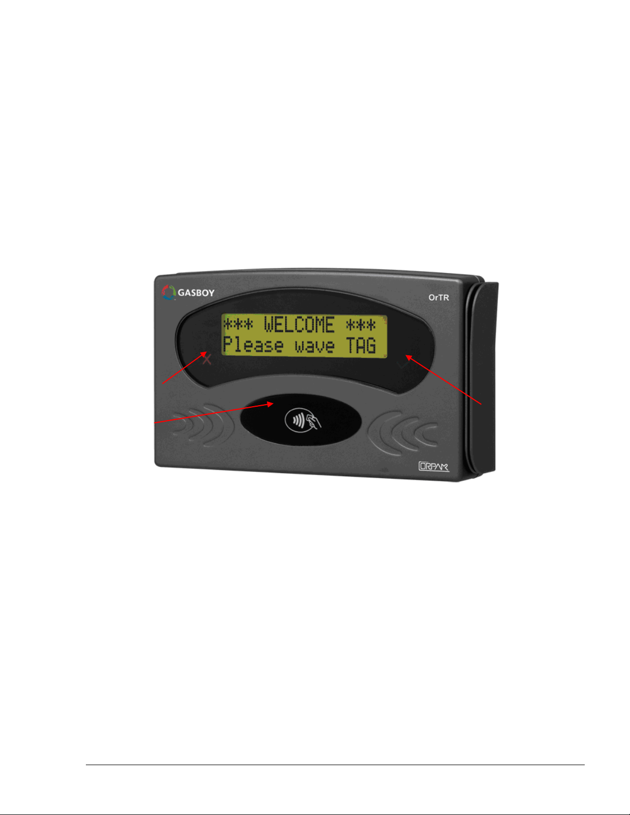
Two LEDs on the Tag Reader front panel indicate the transaction status:
Green – - Positive recognition, transaction was authorized
Red – - Negative recognition, transaction is not authorized.
The indicators are automatically activated by the station Controller when the customer places the
tag or card near the tag reader, close to the sensing component located at the bottom of the front
panel (see Figure 1-1).
A welcome message is displayed on the TR display, and is replaced by messages which indicate the
progress of the transaction. The display is backlit for improved readability under poor lighting
conditions. An internal speaker provides audio feedback.
Red LED
Contactless
Reader
Green
LED
Figure 1-1. Tag Reader, General view
Tag Reader Installation Guide
5
Page 10

1-3.
1-3.
FUNCTIONAL DESCRIPTION
FUNCTIONAL DESCRIPTION
1-3.1. Main Features
The TR is based on advanced technology, implemented by two microcomputer subsystems: one for
handling the secure communication protocol with the tag/card, and the other for communication
with the station Controller and for controlling the operation of TR.
The Tag Reader includes a single cable carrying power and RS485 communication.
The Tag Reader user interface (UI) can easily be adapted to the customer requirements. For
flexibility, the Tag Reader uses a standard communication protocol, and the displayed messages are
controlled by the station Controller.
The message contents and language can be selected by the system operator, and the microcomputer
application software can be updated in the field.
1-3.2. Supported Cards/Tags Options
Tag Reader has several configurations and can support various cards and tags, including: MiFare,
magnetic fuel and fleet cards and optional payment contact less cards.
1-3.2.1. MiFare Tag/Card
This is a contact less card that can be used as a fueling card by the driver at the gas station. When
the card is presented next to the TR, it reads the card / tag data and transmits it to the station controller
in the gas station. Upon verification and approval, the station Controller activates and releases the pump
valve, so fuel can be dispense to the vehicle.
Four types of tags are recognized:
Driver’s tag: this tag is used to identify a specific driver. Therefore, fuel dispensing is
allowed only after the vehicle has been identified by means of its Vehicle Identification Unit
(VIU).
Vehicle’s tag: this tag is used to authorize fuel dispensing and charging.
Attendant’s tag: permits operation of any fuel nozzle from the TR, by a station attendant.
Technician tag: this tag is used to setup TR RS-485 address, as explained in para. 1-3.4.
Figure 1-2. MiFare Tag, General view
6
Tag Reader Installation Guide
Page 11

1-3.2.2. Magnetic Stripe Fuel Cards
If the TR is equipped with an optional magnetic card reader, at the right-hand side of the unit, the
driver can use a magnetic stripe card.
A magnetic stripe card is a type of card capable of storing data. The magnetic stripe is read by
physical contact and swiping past a reading head.
The driver may have a vehicle fuel card or personal driver card.
1-3.2.3. Payment Contact Less Cards (optional)
Payment contactless cards such as the PayPass® cards enable the driver to pay using a standard
credit or debit card which has contact less capabilities.
This allows the home-base station to be semi-public and accept payment from occasional customers
and process the transaction through the bank or local processing network.
TR has an optional PayPass reader to support these types of cards
1-3.3. Serial Communication Interface
The TR has a balanced bidirectional RS-485 communication interface, which connects to the CFN
PLUS of the gas station or tanker truck.
This interface is used to communicate with the station controller.
The power and communication cable has five wires: two power supply wires, two wires for the
communication interface and one Ground Wire (see
Figure 1-3).
Wire Color Functional Description
Green Power (+)
White Power (-)
Red RS-485 (+)
Black RS-485 (-)
Shield Shield
Tag Reader Installation Guide
7
Page 12
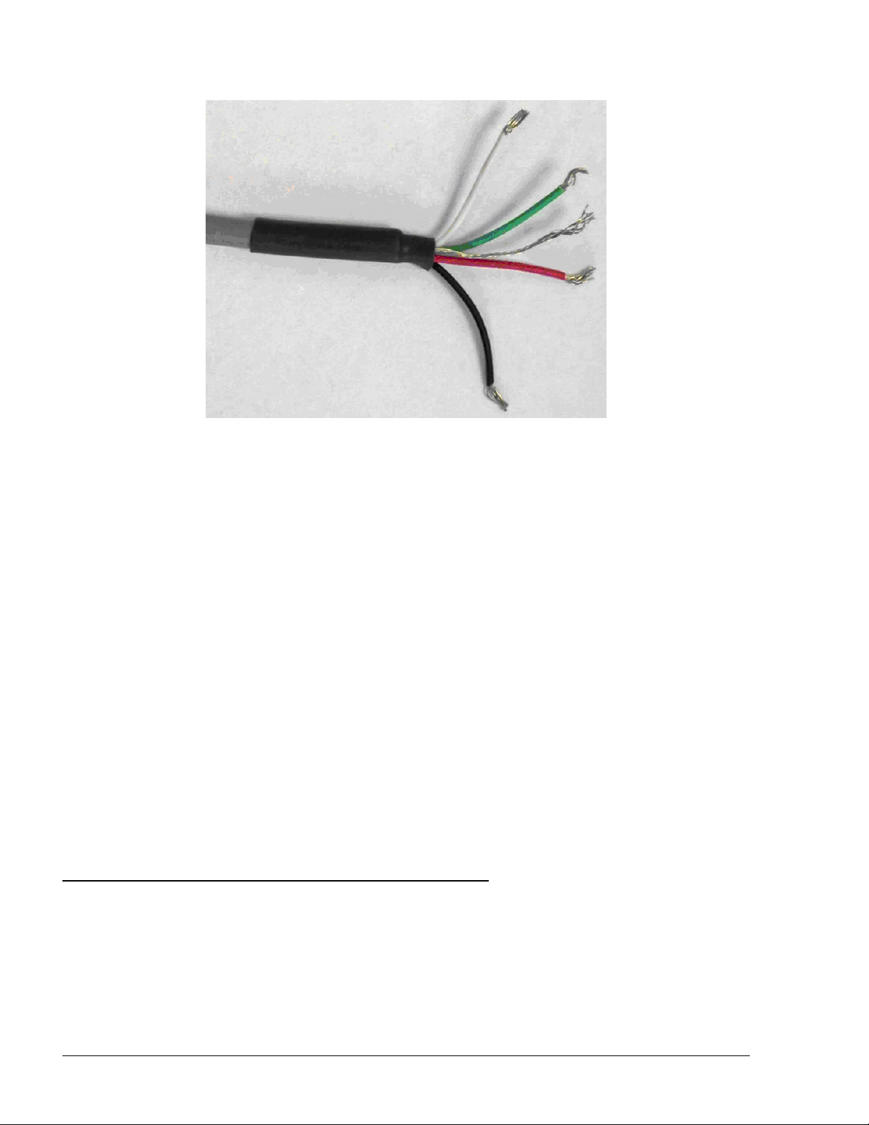
Figure 1-3 Tag Reader. Power and Communication Cable
The same interface can be used for maintenance purposes, e.g., to download software updates,
configure various parameters, select the RS-485 communication address, etc. For such purposes,
1-3.4. Assigning Tag Reader RS-485 Address
1-3.5. Assigning TR RS-485 Address
To enable communication with the station controller, the TR must be assigned a unique RS-485
address. This address must be selected by the system operator, during the planning stages of the
system installation or upgrading.
The RS-485 address of the TR can be programmed in two ways:
Contact less mode: the address is selected using the Technician tag. The selection is
performed using a simple interactive process: The Technician tag is brought close to be read
by the TR, which then starts sequentially displaying the addresses in the allowed range.
When the prescribed address is displayed, the Technician tag is removed.
By a PC directly connected to TR RS-485 interface.
1-4.
1-4.
POWER SUPLY
POWER SUPLY
The TR requires 12 to 24 VDC power input. Power can be provided by the CFN PLUS or an
external power supply. If an external power supply is used, it should be approved in accordance
with local regulations.
8
Tag Reader Installation Guide
Page 13
In North America, use a NEC Class 2 power supply, low voltage and low current [maximum
100 VA even under fault conditions]. The adaptor can be installed in the office, in the installation
pole or pedestal, or in a separate box.
The TR is provided with DC connection cables protruding from the rear panel for easy connection.
NNOOTTEE
If the power supply is installed far from the TR box,
make sure the TR receives a correct voltage! There
may be a power failure on the lines!
1-5.
1-5.
HOUSING
HOUSING
The Tag Reader system enclosure is made of rugged plastic, in the form of a small box. The
enclosure is weather-proof in order to sustain the harsh environment of a Home Base Station. The
devices in its front panel are sealed to prevent humidity and dust penetration.
1-6.
1-6.
SPECIFICATIONS
SPECIFICATIONS
1-6.1. Operational
User Interface – Alphanumeric LCD
Dual-LED green and red indicators
Piezoelectric speaker
Readers - Contactless MiFare reader
Magnetic card reader (optional)
Payment contactless cards reader (optional)
Display Type – Backlit alphanumeric LCD with 5×7 dot matrix display units
Display Size – 2 rows of 16 characters each
1-6.2. Communication Interface
RS- 485
1-6.3. Physical
Height – 140 mm (5.1 in.)
Width – 210 mm (8.3 in.)
Depth – 38 mm (1.5 in.)
Weight – 480 gram (1.1 lb.)
(see Figure 1-4).
1-6.4. Power
Operating voltage - 12 - 24 V DC.
Tag Reader Installation Guide
9
Page 14

Operating current - 0.5 A
Figure 1-4. Tag Reader – Dimensions
1-6.5. Environmental
Operating temperature : -40 - +70 °C (-40 – 158 °F)
Storage temperature : -40 - +70 °C (-40 – 158 °F)
Humidity – 95% RH
Degrees of Protection - IP66
1-7.
1-7.
TYPES
TYPES
The TR can be obtained in several contact less models, in accordance with the functional options:
Contactless readers: MiFare, or PayPass
Connectivity: RS485
With or without magnetic card reader
10
Tag Reader Installation Guide
Page 15

1-8.
1-8.
STANDARDS
STANDARDS
1-8.1. Communication Standard
The Tag Reader communicates, in its different models, over the following standard:
RS-485 link
1-8.2. Security Standards
Tag Reader has a Security Authentication Module (SAM) used to decrypt the card/tag data.
1-9.
1-9.
MANUAL STRUCTURE
MANUAL STRUCTURE
This manual comprises of the following sections:
Section 1: General Description
This section provides a general description of the Tag Reader system.
Section 2: Installation Procedures
This section provides the preliminary installation requirements and procedures to be performed
before installing Tag Reader.
Section 3: Maintenance and Troubleshooting
This section provides basic troubleshooting procedures for the Tag Reader.
Tag Reader Installation Guide
11
Page 16

1-10.
1-10.
USING THIS MANUAL
USING THIS MANUAL
This manual includes alerting comments inserted along the document, in order to draw the reader’s
attention to important issues. The comments are accompanied by symbols for ease of reference.
The following comment types are used:
WWAARRNNIINNGG
An operating procedure, practice, etc', that if not
correctly followed, could result in injury or loss of
life.
CCAAUUTTIIOONN
An operating procedure, practice, etc', that if not
strictly observed, could result in damage to, or
destruction of equipment.
TTIIPP
This note is aimed for using the system in better
efficiently way.
NNOOTTEE
This comment is of importance for emphasizing.
IINNSSIIGGHHTT
More detailed technical/ functional information in
regard relevant issue.
12
Tag Reader Installation Guide
Page 17
0
SECTION 2
SECTION 2
IN
IN
STALLATION
2-1.
2-1.
This section provides installation and configuration instructions for the Tag Reader, and instructions
for solving problems that may occur during installation and operation
The Tag Reader is designed to be installed in a non hazardous location in the station or tanker truck
in both indoors and outdoors installation. The Tag Reader is intended for installation outside the
associated fuel pump, on the side accessible to the customer (at an area defined as safe area).
The Tag Reader is designed to be installed in a non hazardous location in the station.
Three installation alternatives are available:
GENERAL
1. Installation on a wall or pole
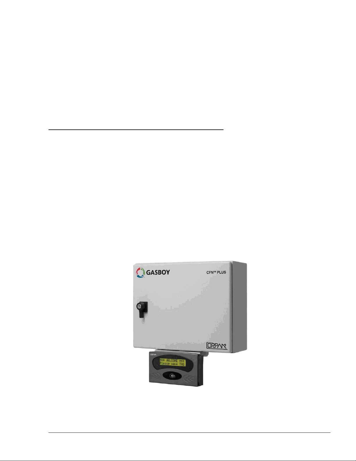
2. Together with the CFN PLUS station controller. See Figure 2-3 for instructions.
3. In fueling trucks, as part of the TC solution
GENERAL
STALLATION
Figure 2-1 – Tag Reader beneath CFN PLUS
Tag Reader Installation Guide
13
Page 18
2-2.
2-2.
TOOLS AND ACCESSORIES
TOOLS AND ACCESSORIES
Tag Reader can be provided with an installation kit for the Tag Reader, which includes a rubber
seal, P/N 8149-27400, and four M4 × 20 screws, P/N 8152-03120, with spring washers.
No special tools are required for installing the Tag Reader. Make sure you have 4 mm, 4.4 mm and
5mm drill bits.
2-3.
2-3.
LOCATIONS
LOCATIONS
The Tag Reader can be installed in several Unclassified/Non-Hazardous Locations:
Attached to a station controller box (CFN PLUS) and Over Class 1 Division 2 Group D
Attached to a Tanker Truck controller box and Over Class 1 Division 2 Group D
On a pole or wall mounted close to the station dispensers.
Connected to the station controller box (CFN PLUS) in the station office or in any other
non-explosive environment.
If no suitable walls or poles are available, the Tag Reader can be installed on a dedicated
pole. In that case, setting the pole in the island must comply with the UL/EU or any local
regulations requirements such as cementing the pole to the island floor, laying cables and
keeping the Tag Reader Box outside Class I zone, as described in paragraph 2-4.
Inside the driver compartment of a tanker truck
NNOOTTEE
Maximum distance of the RS-485 communication
line between Tag Reader and Controller box is 330
feet (100m).
More than one Tag Reader can be mounted in one station for improved service. In this case all Tag
Readers shall be connected to the same, single CFN PLUS via RS-485.
The preferred installation method depends on the layout and configuration of the gas station. Any of
the above selected methods must comply with UL and EU requirements.
CCAAUUTTIIOONN
The Tag Reader must NOT be installed on the
dispenser or in any other hazardous environment.
2-4.
2-4.
SAFETY LIMITATIONS
SAFETY LIMITATIONS
Due to safety requirements, the Tag Reader box can be installed only in non-hazardous areas/
non-classified area. Hazardous areas are shown in grey in the control drawing (see Figure 2-2).
Therefore, the Tag Reader must be installed within the following boundaries:
14
Tag Reader Installation Guide
Page 19

1. Above 18” (0.5 meter) from the island floor
2. At least 18” (0.5 meter) away from the dispenser
Figure 2-2 shows various possible installation locations for the Tag Reader Box.
Figure 2-2. Tag Reader, Outdoor Installation Control Drawing
2-5.
2-5.
INSTALLATION INSTRUCTIONS
INSTALLATION INSTRUCTIONS
2-5.1. Preparation
The Tag Reader is fastened by means of four M4 × 16 screws to the mounting surface or flange.
The fastening screws pass through holes in the bottom plate of the Tag Reader. In addition, a 0.474"
hole is required to pass the connection cable. The Tag Reader support flange is provided with holes
suitable for attaching the Tag Reader to it. Figure 2-3 shows the drilling marking template for the
Tag Reader.
Tag Reader Installation Guide
15
Page 20

Figure 2-3. Tag Reader Installation Holes, Internal View
2-5.2. General Instructions
The following paragraph provides step by step instructions for installation of the Tag Reader box.
1. Install the Tag Reader in a non-hazardous area in accordance with Figure 2-2.
2. Install the Tag Reader at a height suitable for LCD screen reading by an average driver.
3. Link the Tag Reader to the Controller (CFN PLUS, Islander Plus, Fuel Truck Controller or
other) with the RS-485 wires.
4. Connect Tag Reader to power supply
5. The installation procedures must meet all safety regulations in accordance with local state
regulations.
2-5.3. Mechanical Installation
In this configuration, the Tag Reader is installed on a pole or a wall. Proceed as follows:
1. Verify that the Tag Reader support flange is provided with holes suitable for attaching the
Tag Reader to it (see Figure 2-3)
2. Remove the four M4 x16 screws at the rear panel attaching the rear panel (see
Figure 2-4)
3. Rem
ove the Grommet cap at the center of rear panel and pull out cable from the Tag Reader
4. Insert the free end of the Tag Reader cable through the 12 mm hole, and then place the Tag
Reader rear (with the rubber seal) in the prescribed position on the support flange
5. Attach the unit using four M4 x16 screws from
16
Tag Reader Installation Guide
the rear side
Page 21

6. Install the Tag Reader with support flange to the installation site: Smooth flat surface/Pole/
Dedicated Pole/CFN PLUS (with special flange)
7. Secure the Tag Reader support flange at installation location using the appropriate screws,
spring washers and flat washers. Make sure the rubber seal remains properly seated under
the Tag Reader base.
8. In case of installation to the CFN PLUS, attach a special flange to CFN PLUS lower plate
with two appropriate screws
9. Proceed with the wiring connections (paragraph 2-5.4).
Figure 2-4. Tag Reader Installation Holes and Grommet Cap, Rear View
2-5.4.
2-5.4.
Wiring
The Tag Reader is equipped with a single cable c
Wiring
arrying the Power and Serial Communication
cable. The Tag Reader requires power input and data input/output connections. The RS-485 wires
should be connected to the appropriate CFN PLUS serial communication ports. The cables must be
inserted through dedicated conduits that comply with UL/EU regulations and any other local
regulations. The cables enter the CFN PLUS from the sealing glands that ensure the box sealing.
Proceed as follows:
Tag Reader Installation Guide
17
Page 22

1. Remove appropriate length of cable coating for connection to power supply and RS-485
ports
2. Connect the Tag Reader power wires to a 12-24 VDC (stabilized), 500 mA (minimum)
power supply or to CFN PLUS DC connection ports
3. Connect Tag Reader serial communication wires to the CFN PLUS RS-485 ports
4. Connect coax (shield) wire of RS-485 cable to Ground inside CFN PLUS
5. When installing cables into CFN PLUS Controller, do not damage unit sealing (IP66
protection)
6. Verify that Tag Reader is powered on.
Figure 2-5. Tag Reader with Cables
1.
18
Tag Reader Installation Guide
Page 23

2-5.5.
2-5.5.
Tag Reader Address
Tag Reader Address
Post-Installation Checks and Programming of
Post-Installation Checks and Programming of
Proceed as follows:
1. Restart the CFN PLUS
2. Monitor the power-up indications provided by the Tag Reader:
Check that the green and red indicators turn on for a few seconds and then turn
off.
Check that a single beep is heard.
Check that the LCD displays Tag Reader
software version, followed by the welcome
message.
3. Observe the default OrTR address as displayed on the screen as the device is powered-up,
and then set the new OrTR address using the Host ORPT application, as follows:
a. Connect a PC on which the Host OrPT application was previously installed to OrTR
RS-485 connector via 8-Port Commverter or any other RS-485/RS-232 convertor
b. Run the Host OrPT application. The following screen is displayed (see Figure 2-6):
Figure 2-6. Host OrPT Main Screen
c. Click on the Scan button. The Scan/Set New Address dialog box appears (see Figure
2-7)
Tag Reader Installation Guide
19
Page 24

Figure 2-7. Scan/Set New Address Dialog Box
d. Enter the address range to be scanned using the Scan From and To spin boxes and
then click on the Scan button
e. The application displays all the allowed addresses in ascending order on the bottom
of the screen
f. Click on the required address and then click Choice
g. The selected address in displayed on the New Address spin box. Click Set to assign
the new address to the device
h. Click Close to exit the dialog box
i. Click Exit on the OrPT Host Main Screen to close the application
The OrTR is now ready for use.
20
Tag Reader Installation Guide
Page 25

0
SECTION 3
SECTION 3
US
US
ING TAG READER
3-1.
3-1.
This section provides a description of the customer's interaction with the Tag Reader.
For a regular Fuel Dispensing procedure, proceed as follows:
GENERAL
1. When ready for service, the Tag Reader displays a
welcome message, and its two indicators, green and
red , are both off.
2. A customer wishing to start fuel dispensing needs to bring his tag/card near the ”tap” icon
on the Tag Reader, as shown in Figure 3-1.
GENERAL
S
NNOOTTEES
The following messages are usually displayed.
However, they may be changed at the setup of the
Station Controller
ING TAG READER
Figure 3-1. Starting Fuel Dispensing
Tag Reader Installation Guide
21
Page 26

3. The two Tag Reader indicators, green and red ,
flash for a few seconds to indicate that it reads the
tag/card, a beep is heard, and the customer sees a
notification message:
4. After the tag/card is successfully read, only the green
indicator continues to flash. The Tag Reader waits for a
confirmation or rejection message from the station
controller, and notifies the customer to wait:
5. After tag/card OK is displayed, the customer can remove the tag/card.
6. If everything is OK, the station controller confirms the
transaction within 10 seconds. The green indicator
turns on (or flashes) and the customer is notified to start
refueling:
7. After refueling is ended by returning the refueling nozzle
to its cradle, the customer see the following message:
3-2.
3-2.
ERROR CONDITIONS
ERROR CONDITIONS
In case an error occurs after the customer starts a refueling in accordance with para. 3-1, the red
indicator turns on (or starts flashing) and a beep is heard. The cause of the error is displayed on the
LCD.
Error during the reading of information from the tag or
card. In this case, after step 3 the following message is
displayed: In this case, the customer should wait until the
welcome message appears, and bring again the tag/card
close to Tag Reader.
In case the problem occurs again, the customer should contact one of the station attendants.
The tag/card is rejected by the station controller. In this
case, after step 5 the following message is displayed: In
this case, the customer should contact one of the station
attendants.
22
Tag Reader Installation Guide
Page 27

0
SECTION 4
SECTION 4
MA
MA
INTENANCE
4-1.
4-1.
This section provides general maintenance and troubleshooting instructions for the Tag Reader.
4-2.
4-2.
4-2.1. General
The Tag Reader itself as a standalone unit should be cleaned periodically at short intervals, due to
the harsh environment of the Home Base Station where they operate.
GENERAL
CLEANING
GENERAL
CLEANING
CCAAUUTTIIOONN
INTENANCE
DO NOT use any solvents such as thinner or
benzene.
4-2.2. Cleaning Instructions
The Tag Reader should be cleaned periodically, preferably once every two (2) weeks, in order to
ensure proper operation. The cleaning purpose is to remove any dust or foreign body that may
harm the reader and consequently prevent the completion of a sale.
Proceed as follows:
Clean the Tag Reader with a damp cloth only.
Tag Reader Installation Guide
23
Page 28

4-3.
4-3.
TROUBLESHOOTING
TROUBLESHOOTING
Table 4-1 lists the recommended procedures for troubleshooting the Tag Reader.
Table 4-1. Tag Reader, Troubleshooting Procedures
No. Symptom Troubleshooting Procedure Recommended Action
1 Display is off Check DC Voltage power supply
output
Check the proper connection between
the Power Supply and Tag Reader
2 No communication
between Tag Reader and
the controller
Check RS-485 and CAT-5E cables
connection between Tag Reader and
controller
3 LEDs are not operating Check DC Voltage power supply
output
Replace DC Voltage
power supply
Wire the unit anew.
Replace Tag Reader
Replace DC Voltage
power supply
24
Tag Reader Installation Guide
 Loading...