

Page 1

Introduction
This manual provides instructions to install the Submersible Drive Relay Kit (M05816K00X)
for the direct drive of submersible pumps, up to 3/4hp, 120v and up to 1-1/2hp, 240v (not
required with external relay box).
Intended Users
This manual is intended for Gasboy Authorized Service Contractors (ASCs).
Single and Dual Relay Kits
MDE-4596
Atlas™ Submersible Drive Relay Kits
(M05816K00X)
Installation Instructions
August 2006
Kit No. Description
M05816K001 Single Submersible Drive Relay Kit
M05816K002 Dual Submersible Drive Relay Kit
Required Reading
Before installing a kit, the installer must read, understand, and follow:
• This manual
• NFPA 30A, The Automotive and Marine Service Station Code
• NFPA 70, The National Electric Code
• Applicable federal, state and local codes and regulations
Failure to do so may adversely affect the safe use and operation of the equipment.
Note: This kit must be installed by a Gasboy ASC to ensure warranty.
Required Tools
• # 2 Phillips® screwdriver
• # 1 Phillips screwdriver
MDE-4596 Atlas™ Submersible Drive Relay Kits (M05816K00X) Installation Instructions · August 2006 Page 1
Page 2

Parts List
Parts List for Single (M05816K001) and Dual (M05816K002) Atlas Submersible Drive Relay Kits
M05816K001
Description Part Number
Cable Assembly, Single Relay M04956A004 1 Cable, Single Relay M04659A004 1 Relay 120/240V 45W 3/4HP Q11008-01 1 2
Cable Assembly, Dual Relay M04956A005 - 1
Cable, Dual Relay M04659A005 - 1
Screw, M4 X 8 Thread Forming M00417B224 2 4
Atlas™ Submersible Drive Relay
Kits (M05816K00X)
Installation Instructions
MDE-4596 1 1
Quantity
M05816K002
Quantity
Page 2 MDE-4596 Atlas™ Submersible Drive Relay Kits (M05816K00X) Installation Instructions · August 2006
Page 3
Important Safety Information
Important Safety Information
This section introduces the hazards and safety precautions
associated with installing, inspecting, maintaining or servicing
this product. Before performing any task on this product, read
this safety information and the applicable se cti on s in th is
manual, where additional hazards and safety precautions for
your task will be found. Fire, explosion, electrical shock or
pressure release could occur and cause death or serious
injury if these safe service procedures are not followed.
Preliminary Precautions
You are working in a potentially dangerous environment of
flammable fuels, vapors, and high voltage or pressures. Only
trained or authorized individuals knowledgeable in the related
procedures should install, inspect, maintain or service this
equipment.
Emergency Total Electrical Shut-Off
The first and most important information you must know is
how to stop all fuel flow to the pump and island. Locate the
switch or circuit breakers that shut-off all power to all fueling
equipment, dispensing devices, and submerged turbine
pumps (STPs).
!
WARNING
!
The EMERGENCY STOP, ALL STOP, and
PUMP STOP buttons at the cashier’s station
WILL NOT shut off electrical power to the
pump/dispenser.
Read the Manual
Read, understand and follow this manual and any other
labels or related materials supplied with this equipment. If
you do not understand a procedure, call a Gasboy Authorized
Service Contractor or call the Gasboy Service Center at
1-800-444-5529. It is imperative to your safety and the safety
of others to understand the procedures before beginning
work.
Follow the Regulations
There is applicable information in NFPA 30A; Automotive and
Marine Service Code, NFPA 70; National Electrical Code (NEC),
OSHA regulations and federal, state, and local codes which
must be followed. Failure to install, inspect, maintain or
service this equipment in accordance with these codes,
regulations and standards may lead to legal citations with
penalties or affect the safe use and operation of the
equipment.
Replacement Parts
Use only genuine Gasboy replacement parts and retrofit kits
on your pump/dispenser. Using parts other than genuine
Gasboy replacement parts coul d cre at e a safety ha za rd and
violate local regulations.
Safety Symbols and Warning Words
This section provides important information about warning
symbols and boxes.
Alert Symbol
Total Electrical Shut-Off Before Access
Any procedure requiring access to electrical components or
the electronics of the dispenser requires total electrical shutoff of that unit. Know the function and location of this switch
or circuit breaker before inspecting, installing, maintaining, or
servicing Gasboy equipment.
Evacuation, Barricading and Shut-Off
Any procedures requiring accessing the pump/dispenser or
STPs requires the following three actions:
- An evacuation of all unauthorized persons and vehicles
using safety tape, cones or barricades to the effected units
- A total electrical shut-off of that unit
This means that even if you activate these
stops, fuel may continue to flow uncontrolled.
You must use the TOTAL ELECTRICAL SHUTOFF in the case of an emergency and not only
these cashier station “stops.”
on warning labels to alert you to a precaution which must be
followed to prevent potential personal safety hazards. Obey
safety directives that follow this symbol to avoid possible
injury or death.
Signal Words
These signal words used in this manual and on warning
labels tell you the seriousness of particular safety hazards.
The precautions that follow must be f oll owed to prevent
death, injury or damage to the equipment.
CAUTION with Alert symbol: Designates a hazard or
unsafe practice which may result in minor injury.
CAUTION without Alert symbol: Designates a hazard
or unsafe practice which may result in property or
equipment damage.
This safety alert symbol is used in this manual and
DANGER: Alerts you to a hazard or unsafe practice
!
which will result in death or serious injury.
!
WARNING: Alerts you to a hazard or unsafe practice
that could result in death or serious injury.
!
Working With Fuels and Electrical Energy
Prevent Explosions and Fires
Fuels and their vapors will become explosive if ignited.
Spilled or leaking fuels cause vapors. Even filling customer
tanks will cause explosive vapors in the vicinity of dispenser
or island.
MDE-4596 Atlas™ Submersible Drive Relay Kits (M05816K00X) Installation Instructions · August 2006 Page 3
Page 4
Important Safety Information
No Open Flames
Open flames from matches, lighters, welding torches or other
sources can ignite fuels and their vapors.
No Sparks - No Smoking
Sparks from starting vehicles, starting or using power tools,
burning cigarettes, cigars or pipes can also ignite fuels and
their vapors. Static electricity, including an electrostatic
charge on your body, can cause a spark sufficient to ignite
fuels and their vapors. After getting out of a vehicle, touch the
metal of your vehicle to discharge any electrostatic charge
before you approach the dispenser island.
Working Alone
It is highly recommended that someone who is capable of
rendering first aid be present during servicing. Be familiar
with Cardiopulmonary Resuscitation (CPR) methods if you
are working with or around high voltages. This information is
available from the American Red Cross. Always advise the
station personnel about where you will be working, and
caution them not to activate power while you are working on
the equipment. Use the OSHA tag out and lock out
procedures. If you are not familiar with this requirement, refer
to information in the service manual and OSHA
documentation.
Working With Electricity Safely
Be sure to use safe and established practices in working with
electrical devices. Poorly wired devices may cause a fire,
explosion or electrical shock. Be sure grounding connections
are properly made. Make sure that sealing devices and
compounds are in place. Be sure not to pinch wires when
replacing covers. Follow OSHA Lock-Out and Tag-Out
requirements. Station employees and service contractors
need to understand and comply with this program completely
to ensure safety while the equipment is down.
Emergency First Aid
Informing Emergency Personnel
Compile the following information and inform emergency
personnel:
• Location of accident (for example, address, front/back of
building, and so on)
• Nature of accident (for example, possible heart attack,
run over by car , burn s, and so on)
• Age of victim (for example, baby, teenager, middle-age,
elderly)
• Whether or not victim has received first aid (for example,
stopped bleeding by pressure, and so on)
• Whether or not a victim has vomited (for example, if
swallowed or inhaled something, and so on)
WARNING
!
Gasoline ingested may cause unconsciousness
and burns to internal organs.
Do not induce vomiting.
Keep airway open.
Oxygen may be needed at scene.
Seek medical advice immediately.
WARNING
!
Gasoline inhaled may cause unconsciousness
and burns to lips, mouth and lungs.
Keep airway open.
Seek medical advice immediately.
WARNING
!
Gasoline spilled in eyes may cause burns to eye
tissue.
Irrigate eyes with water for approximately 15
minutes.
Seek medical advice immediately
Hazardous Materials
WARNING
Some materials present inside electronic enclosures may
present a health hazard if not handled correctly. Be sure to
clean hands after handling equipment. Do not place any
equipment in mouth.
!
WARNING
This area contains a chemical known to the State of
California to cause cancer.
!
Gasoline spilled on skin may cause burns.
Wash area thoroughly with clear/water.
Seek medical advice immediately.
IMPORTANT: Oxygen may be needed at scene if gasoline
has been ingested or inhaled. Seek medical advice
immediately.
Lockout/Tagout
WARNING
!
Lockout/Tagout covers servicing and maintenance of
machines and equipment in which the unexpected
This area contains a chemical known to the State of
California to cause birth defects or other reproductive
harm.
energization or start up of the machine(s) or equipment or
release of stored energy could cause injury to employees or
personnel. Lockout/Tagout applies to all mechanical,
hydraulic, chemical or other energy, but does not cover
electrical hazards. Reference Subpart S of 29 CFR Part 1910
IMPORTANT: Oxygen may be needed at scene if gasoline
has been ingested or inhaled. Seek medical advice
- Electrical Hazards, 29 CFR Part 1910.333 contains specific
Lockout/Tagout provision for electrical hazards.
immediately.
Page 4 MDE-4596 Atlas™ Submersible Drive Relay Kits (M05816K00X) Installation Instructions · August 2006
Page 5
Installing the Atlas Submersible Drive Relay Kit
Installing the Atlas Submersible Drive Relay Kit
Preparing for the Installation
1 Request permission from the manager/owner to turn off the circuit breakers for MICRO,
LIGHTS and FEED. Perform the lockout/tagout safety procedures.
2 Ensure that you have the proper kit for the model unit to be retrofitted.
3 Follow all applicable safety rules and procedures.
Installing the Atlas Submersible Drive Relay Kits
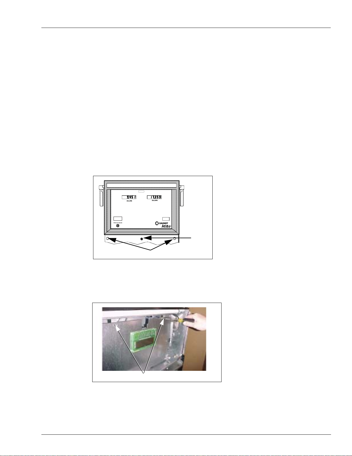
1 Unlock and remove the front panel.
Unlock
Bezel Screws (behind front panel)
2 Remove the two screws securing the bezel assembly and remove the assembly.
3 Remove the two screws securing the display panel and pivot display panel down. The unit will
swing forward and down after screws are removed.
Screws
MDE-4596 Atlas™ Submersible Drive Relay Kits (M05816K00X) Installation Instructions · August 2006 Page 5
Page 6
Installing the Atlas Submersible Drive Relay Kit
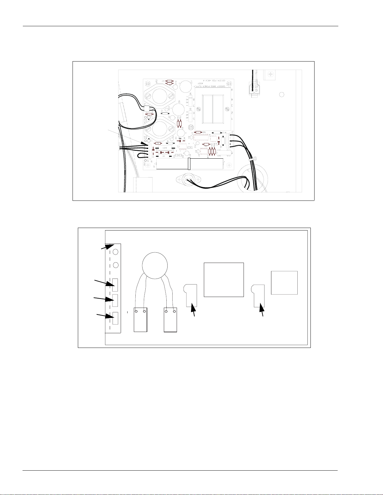
4 Pull the connector off P1 on the power supply. After a few seconds, reconnect P1.
P1
5 Attach the relay module to the platform base using M4 screws.
L bracket
Main
Conduit
Micro
power
Lights
Heater
K1-1 K1-2
Relay
1
Single
K2-1
K2-2
Relay
2
Dual
CPU
Pulser
Power
supply
Pulser
Note: Single dispensers will use only relay 1, whereas twins will use both relays (1 and 2).
6 Attach the relay cable to P7 of the display CPU board. 7 Locate the 14 gauge red and blue wires coming from the AC conduit under the platform
(marked K1-1 and K1-2 respectively). Dual dispensers will also use the 14-gauge orange and
black wires (marked K2-1 and K2-2 respectively).
8 Attach the red wire to screw terminal #1 and the blue wire to screw terminal #2 of relay #1.
Attach the orange wire to screw terminal #1 and the black wire to screw terminal #2 of relay
#2.
9 Complete the wiring between the breaker panel, pump and AC J-Box as shown in FE357B
Atlas Pump Retail/Commercial Field Wiring Diagram.
Page 6 MDE-4596 Atlas™ Submersible Drive Relay Kits (M05816K00X) Installation Instructions · August 2006
Page 7

Installing the Atlas Submersible Drive Relay Kit
Completing the Installation
1 Reassemble the pump (fasten the display panel in place, install and secure the bezel assembly,
and install and lock the front panel).
2 Inform the manager/owner that the circuit breakers for MICRO, LIGHTS and FEED will be
turned on and then turn them on.
3 Remove the lockout/tagout and return to normal operation.
MDE-4596 Atlas™ Submersible Drive Relay Kits (M05816K00X) Installation Instructions · August 2006 Page 7
Page 8

Installing the Atlas Submersible Drive Relay Kit
.
™
Atlas
is a registered trademark of Gasboy. Phillips® is a registered trademark of Phillips Screw Company.
© 2006 GASBOY
7300 West Friendly Avenue • Post Office Box 22087
Greensboro, North Carolina 27420
Phone 1-800-444-5529 • http://ww w.gasboy.com • Printed in the U.S.A.
MDE-4596 Atlas™ Submersible Drive Relay Kits (M05816K00X) Installation Instructions · August 20 06
 Loading...