

Page 1
MDE-481
7G
SiteOmat In-House Station Controller
SETUP and MAINTENANCE MANUAL
This manual supports released version 6.4.45
This document is based on Orpak’s SiteOmat setup and maintenance
manual P/N 817423756
Page 2

Page 3

SAFETY CONSIDERATIONS
Read all warning notes and instructions carefully. They are included to help you installing the Product safely
in the highly flammable environment of the fuel station. Disregarding these warning notes and instructions
could result in serious injury or property damage. It is the installer responsibility to install, operate and
maintain the equipment according to the instructions given in this manual, and to conform to all applicable
codes, regulations and safety measures. Failure to do so could void all warranties associated with this
equipment.
Remember that the fuel station environment is highly flammable and combustible. Therefore, make sure
that actual installatio
a flammable environment, according to the local regulations and relevant standards.
Use separate conduit for the intrinsically safe. Do not run any other wires or cables through this conduit,
because this could create an explosion hazard.
Use standard test equipment only in the non- hazardous area of the fuel station, and approved test equipment
for the hazardous areas.
In the installation and maintenance of the Product, comply with all applicable requirements of the National
Fire Protection Association NFPA-30 “Flammable and Combustible Liquids Code”, NFPA-30A “Code for
Motor Fuel Dispensing Facilities and Repair Garages”, NFPA-70 “National Electric Code”, federal, state and
local codes and any other applicable safety codes and regulations.
Do not perform m
operations could ignite fuel vapors and flammable liquids, resulting in death, serious personal injury,
property loss and damage to you and other persons.
Dangerous AC voltages that could cause death or serious personal injury are used to power the Product.
Always disconnect power before starting any work. The Product has more than one power supply connection
points. Disconnect all power before servicing.
When working in any open area of fuel station, beware of passing vehicles that could hit you. Block off the
work area to protect yourself and other persons. Use safety cones or other signaling devices.
n is performed by experienced personnel, licensed to perform work in fuel station and at
WARNING - EXPLOSION HAZARD
etal work in a hazardous area. Sparks generated by drilling, tapping and other metal work
CAUTION - SHOCK HAZARD
WARNING – PASSING VEHICLES
WARNING
Components substitutions could impair intrinsic
Attaching unauthorized components or equipment will void your
safety.
warranties.
Page 4

CAUTION
Do not attempt to make any repair on the printed circuit boards residing in the Product, as this will void all
warranties related to this equipment.
PROPRIETY NOTICE
This document contains propriety and confidential information. It is the property of ORPAK SYSTEMS
Ltd. It may not be disclosed or reproduced in whole or in part without written consent of ORPAK
SYSTEMS. The information in this document is current as of the date of its publication, but is subject to
change without notice.
DISCLAIMER
This document i
ORPAK SYSTEMS does not guarantee that there are no errors or omissions in this document.
s provided for reference only. Although every effort has been made to ensure correctness,
FCC Compliance Statement
The FCC Wants You to Know:
This equipment
pursuant to Part 15 of the FCC rules. These limits are designed to provide reasonable protection against
harmful interference in a residential installation. This equipment generates uses and can radiate radio
frequency energy and, if not installed and used in accordance with the instructions, may cause harmful
interference to radio communications. However, there is no guarantee that interference will not occur in a
particular installation. If this equipment does caus
which can be determined by turning the equipment off and on, the user is encouraged to try to correct the
interference by one or more of the following measures :
a) Reorient
b) Increase the separation between the equipment and receiver.
c) Connect the equipment to an outlet on a circuit different from that to which the receiver is connected.
d) Consult the dealer or an experienced radio/TV technician.
has been tested and found to comply with the limits for a Class B & C digital device,
e harmful interferen
or relocate the receiving antenna.
FCC Warning
Modifications not expressly approved by the manufacturer could void the user authority to operate the
equipment under FCC Rules.
ce to radio or television reception,
This document is the property of:
ORPAK Systems Ltd.
ISRAEL
Page 5

SiteOmat Setup and Mainte nance Manual – MDE 4817G
TABLE OF CONTENTS
Paragraph
1 GENERAL
DESCRIPTION
Page
1-1. INTRODUCTION .............................................................................................................. 21
1-2. SITEOMAT ........................................................................................................................ 22
1-2.1. Overview ........................................................................................................................ 22
1-2.2. Interfaces ........................................................................................................................ 22
1-2.3. Internal Communication Alternatives ............................................................................ 24
1-2.4. External Communication Alternatives........................................................................... 24
1-2.5. Data Access Methods..................................................................................................... 24
1-3. ORCU ................................................................................................................................. 24
1-4. SYSTEM WORKFLOW – EXAMPLES ........................................................................... 26
1-4.1. General ........................................................................................................................... 26
1-4.2. Refueling Scenario with FuelPoint PLUS ..................................................................... 26
1-4.3. Refueling Scenario with Magnetic Cards ...................................................................... 26
1-4.4. Refueling Scenario with 2 devices (2 stage authorization)............................................ 26
1-5. MANUAL STRUCTURE .................................................................................................. 27
1-6. USING THIS MANUAL.................................................................................................... 28
1-7. REFERENCES ................................................................................................................... 29
2 PRE-SETUP
2-1. GENERAL.......................................................................................................................... 30
2-2. SETUP DEFINITION INFORMATION ........................................................................... 30
2-2.1. Required Setup Information........................................................................................... 30
2-2.2. Required Setup Information – Example......................................................................... 30
2-3. SITE SURVEY ................................................................................................................... 31
2-4. ETHERNET NETWORK ADDRESSES ........................................................................... 32
2-4.1. Network Addresses for Controller Internal Devices...................................................... 32
2-4.2. Serial Addresses for Controller Devices ........................................................................ 32
2-5. NAVIGATION NOTES ..................................................................................................... 38
2-5.1. Not Saving Change ........................................................................................................ 38
2-5.2. Saving Data .................................................................................................................... 38
2-5.3. Errors.............................................................................................................................. 38
INFORMATION
I
Page 6

II
SiteOmat Setup and Mainte nance Manual – MDE 4817G
TABLE OF
CONTENTS
Paragraph Page
2-5.4. Confirmation .................................................................................................................. 39
2-5.5. Success ........................................................................................................................... 40
2-6. CONFIGURATION AND SETUP PROCEDURES .......................................................... 40
2-7. BYPASS FEATURE FOR MECHANICAL PUMPS ........................................................ 42
3 OrCU ADMINSTRATION
SCREEN
3-1. GENERAL .......................................................................................................................... 43
3-2. TECNICIAN PC SOFTWARE REQUIRMENTS ............................................................. 43
3-3. INITIAL SETUP PROCEDURES...................................................................................... 43
3-4. SYSTEM INFORMATION ................................................................................................ 45
3-4.1. Versions Screen.............................................................................................................. 46
3-4.2. Largest Files Screen ....................................................................................................... 47
3-4.3. Mini Terminal Screen..................................................................................................... 47
3-4.4. Reboot Unit .................................................................................................................... 48
3-5. SETUP SCREENS .............................................................................................................. 48
3-5.1. Networking..................................................................................................................... 49
3-5.2. Time ............................................................................................................................... 49
3-5.3. Password......................................................................................................................... 50
3-5.4. Serial/ Modem ................................................................................................................ 50
3-5.5. UPS................................................................................................................................. 51
3-6. INSTALLATION SCREENS ............................................................................................. 53
3-6.1. SiteOmat......................................................................................................................... 53
3-6.2. OrData ............................................................................................................................ 55
3-6.3. Pump Server ................................................................................................................... 56
3-6.4. PAIS ............................................................................................................................... 57
3-6.5. Operating System (BSP) ................................................................................................ 57
3-6.5.1. BSP Upgrade Schema................................................................................................ 58
4 SETUP
WIZARD
4-1. GENERAL .......................................................................................................................... 60
4-2. SOFTWARE REQUIREMENTS ....................................................................................... 61
4-3. ACCESSING THE WIZARD............................................................................................. 61
4-3.1. Microsoft Silverlight Installation ................................................................................... 62
4-4. SETUP WIZARD PROCEDURE....................................................................................... 65
4-4.1. Validation of Parameters ................................................................................................ 65
Page 7

III
SiteOmat Setup and Mainte nance Manual – MDE 4817G
TABLE OF
CONTENTS
Paragraph Page
4-4.2. Page 1 - Welcome .......................................................................................................... 65
4-4.3. Page 2 – Global Parameters ........................................................................................... 66
4-4.4. Page 3 - Forecourt Controller Type ............................................................................... 67
4-4.5. Page 4 - Forecourt Setting.............................................................................................. 70
4-4.6. Page 5 - Products ........................................................................................................... 72
4-4.7. Page 7 - Pumps............................................................................................................... 75
4-4.8. Page 8 – Payment ........................................................................................................... 77
4-4.8.1. Product Map .............................................................................................................. 78
4-4.9. Page 9 – Printer .............................................................................................................. 80
4-4.10. Page 10 – Series 1000 Upgrade ..................................................................................... 81
4-4.11. Page 11 – Series 1000 Upgrade ..................................................................................... 82
4-4.12. Page 12 – Backup........................................................................................................... 83
4-4.13. Finalizing the Wizard..................................................................................................... 84
4-5. MAIN SETUP SCREEN – BASIC MODE........................................................................ 85
4-5.1. Functional B
uttons ......................................................................................................... 87
4-6. SETUP WIZARD DEFAULTS.......................................................................................... 87
4-6.1. Ethernet Network Default Addresses............................................................................. 87
4-6.2. Cluster Port Allocation .................................................................................................. 88
4-6.3. Pump Clustering Conventions ....................................................................................... 88
4-6.4. TLG Settings .................................................................................................................. 91
4-6.5. Naming Conventions ..................................................................................................... 91
4-6.6. Cluster Log Port Conventions........................................................................................ 91
4-6.7. Loading Existing Setup .................................................................................................. 92
5 SPECIFIC PARAMETER
SETTINGS
5-1. GENERAL.......................................................................................................................... 93
5-2. MANAGING USERS......................................................................................................... 93
5-2.1. Login .............................................................................................................................. 96
5-2.1.1. Password Change ...................................................................................................... 96
5-2.2. Adding a User ................................................................................................................ 96
5-2.3. Delete a User .................................................................................................................. 98
5-2.4. Updating a User ............................................................................................................. 98
5-3. ACCESS LEVELS ............................................................................................................. 99
5-4. PASSWORD POLICY ....................................................................................................... 100
5-5. REGISTRATION ............................................................................................................... 102
Page 8

IV
SiteOmat Setup and Mainte nance Manual – MDE 4817G
TABLE OF
CONTENTS
Paragraph Page
5-6. PRICE UPDATE ................................................................................................................ 103
5-6.1. Price Lists ....................................................................................................................... 104
5-6.1.1. General ...................................................................................................................... 104
5-6.1.2. Setup .......................................................................................................................... 104
6 ADVANCED SETUP PROCEDURES – GLOBAL
PARAMETERS
6-1. GENERAL .......................................................................................................................... 107
6-2. GLOBAL PARAMETERS ................................................................................................. 109
6-3. ADVANCED STATION PARAMETERS......................................................................... 110
6-3.1. Open Door Detection ..................................................................................................... 114
6-3.2. Payment Terminal Setup ................................................................................................ 114
6-3.2.1. Product Translation ................................................................................................... 116
6-4. RECEIPT ............................................................................................................................ 116
6-4.1. General Settings ............................................................................................................. 117
6-4.2. Defining Formats............................................................................................................ 118
6-5. ALARMS ............................................................................................................................ 122
6-6. COMM (FCC)..................................................................................................................... 123
6-6.1. General ........................................................................................................................... 123
6-7. BACKUP ............................................................................................................................ 126
6-8. SERIES 1000 ...................................................................................................................... 127
6-9. UI TEXT LOCALIZATION............................................................................................... 128
7 ADVANCED SETUP PROCEDURES -
FORECOURT
7-1. GENERAL .......................................................................................................................... 129
7-2. MAIN SETUP SCREEN – ADVANCED MODE ............................................................. 130
7-3. BUSES ................................................................................................................................ 131
7-3.1. General ........................................................................................................................... 131
7-3.2. Settings ........................................................................................................................... 132
7-3.3. Finalizing........................................................................................................................ 133
7-4. PRINTERS.......................................................................................................................... 134
7-5. ORPT .................................................................................................................................. 135
7-5.1. General ........................................................................................................................... 135
7-5.2. Additional Features ........................................................................................................ 135
7-5.3. Finalizing........................................................................................................................ 136
7-6. TAG READERS ................................................................................................................. 137
Page 9

V
SiteOmat Setup and Maintenance Manual – MDE 4817G
TABLE OF
CONTENTS
Paragraph Page
7-7. TANK LEVEL GAUGE – TLG ......................................................................................... 138
7-7.1. General ........................................................................................................................... 138
7-7.2. Probes............................................................................................................................. 138
7-7.2.1. Strapping ................................................................................................................... 140
7-7.2.2. Oil/Water Separator Probe Setting ............................................................................ 141
7-7.2.3. Finalizing Probes Settings ......................................................................................... 142
7-7.3. Sensors ........................................................................................................................... 143
7-7.4. Finalizing Settings ......................................................................................................... 143
7-7.5. Auto Calibration............................................................................................................. 144
7-7.5.1. Tank Calibration Graphs ........................................................................................... 146
7-8. TANKS AND PRODUCTS ............................................................................................... 147
7-8.1. General ........................................................................................................................... 147
7-8.2. Properties ....................................................................................................................... 147
7-8.3. Products.......................................................................................................................... 148
7-8.3.1. General ...................................................................................................................... 148
7-8.3.2. Defining a Base Product............................................................................................ 148
7-8.3.3. Defining a Blended Product ...................................................................................... 149
7-8.4. Defini
ng a Virtual Tank for Blended Fuel ..................................................................... 149
7-8.5. Tank Alarm Settings ...................................................................................................... 150
7-8.5.1. Fuel Leak ................................................................................................................... 150
7-8.5.2. Fuel Volume .............................................................................................................. 150
7-8.5.3. Fuel Density, Fuel Temperature, Water Level .......................................................... 150
7-8.6. Probes Definition ........................................................................................................... 151
7-8.7. Finalizing Settings ......................................................................................................... 151
7-9. VIS AND WGT .................................................................................................................. 152
7-10. PUMP SERVERS ............................................................................................................... 153
7-10.1. General ........................................................................................................................... 153
7-10.2. Additional Features ........................................................................................................ 155
7-10.3. Finalizing the Settings in the Pump Servers Screen ...................................................... 157
7-11. DISPENSERS ..................................................................................................................... 157
7-11.1. General ........................................................................................................................... 157
7-11.2. Message Factors ............................................................................................................. 159
7-11.3. Specific .......................................................................................................................... 159
7-11.3.1. Mechanical Pump Specific Parameters ..................................................................... 160
7-11.3.2. Gasboy Pump Specific Parameters ........................................................................... 161
Page 10

VI
SiteOmat Setup and Mainte nance Manual – MDE 4817G
TABLE OF
CONTENTS
Paragraph Page
7-11.3.3. Gilbarco Pump Specific Parameters .......................................................................... 161
7-11.3.4. Tokheim Pump Specific Parameters ......................................................................... 162
7-11.3.5. Wayne Dart Pump Specific Parameters .................................................................... 162
7-11.4. More Pump Options ....................................................................................................... 163
7-11.5. Finalizing Pump Settings ............................................................................................... 165
7-11.6. Deleting Pump................................................................................................................ 165
7-12. EXPORT/ IMPORT ............................................................................................................ 166
7-12.1. General ........................................................................................................................... 166
7-12.2. Exporting / Saving Setup................................................................................................ 166
7-13. APPLYING THE SETUP SETTINGS ............................................................................... 167
7-14. VERIFYING DEVICES STATUS ..................................................................................... 168
7-15. PIPE FLOW MEASUREMENT......................................................................................... 169
8
MAINTENANCE
8-1. OVERVIEW ....................................................................................................................... 172
8-1.1. Tools and Utilities .......................................................................................................... 173
8-1.2. IP Addresses and Connections ....................................................................................... 175
8-1.3. Regular FCC Maintenance Operation ............................................................................ 175
8-1.3.1. FCC Transaction Limit .............................................................................................. 175
8-1.3.2. Disk Usage Thresholds .............................................................................................. 175
8-1.3.3. Purging Old Data ....................................................................................................... 176
8-1.4. Management File Locations ........................................................................................... 176
8-1.4.1. /usr/local//orpak/BOS/bin .......................................................................................... 176
8-1.4.2. /usr/local/orpak/BOS/bin/log..................................................................................... 176
8-1.4.3. /usr/local/orpak/BOS/DB/patches ............................................................................. 176
8-1.4.4. /usr/local/orpak/BOS/htdocs/* .................................................................................. 176
8-1.4.5. /usr/local/orpak/BOS/reports ..................................................................................... 176
8-1.5. FCC File Locations ........................................................................................................ 176
8-1.6. FCC Loader – Watchdog................................................................................................ 176
8-1.6.1. Pump Server .............................................................................................................. 177
8-1.6.2. Pump Server ‘ini’ Files.............................................................................................. 177
8-1.6.3. Pump Server Factor Settings ..................................................................................... 178
8-2. SYSTEM COMMANDS .................................................................................................... 180
8-2.1. Logging Settings ............................................................................................................ 181
8-3. BACKUP AND RECOVERY ............................................................................................ 185
Page 11

VII
SiteOmat Setup and Mainte nance Manual – MDE 4817G
TABLE OF
CONTENTS
Paragraph Page
8-3.1. Recovery ........................................................................................................................ 186
8-4. LOG FILES ........................................................................................................................ 188
8-4.1. Log File Rotation ........................................................................................................... 188
8-4.2. Log File Format ............................................................................................................. 188
8-4.2.1. General ...................................................................................................................... 188
8-4.2.2. Date/Time Stamp and Thread ID .............................................................................. 189
8-4.2.3. Locating Object ID .................................................................................................... 189
8-4.3. Critical log file ............................................................................................................... 189
8-4.4. BOS Log Files................................................................................................................ 190
8-4.4.1. BOS_REMOTE_HO.log........................................................................................... 190
8-4.4.2. Database Logs (DATA.log, META_DATA.log, LANG.log)................................... 190
8-4.4.3. Web Server Access Logs (WebAccessxxxx.log) ...................................................... 190
8-4.4.4. Web Server Communications Logs (WebCommxxxx.log) ...................................... 190
8-4.4.5. Debug Log (debug.log) ............................................................................................. 191
8-4.5. FCC Log File
s ................................................................................................................ 191
8-4.5.1. FCC_AUTH.log ........................................................................................................ 191
8-4.5.2. Database Logs (DATA.DB.log, META_DATA.DB.log)......................................... 191
8-4.5.3. Bus Logs (BUS_xxx.log) .......................................................................................... 192
8-4.5.4. Pump Server Log FIles.............................................................................................. 194
8-4.5.5. FCC Loader Log (fccloader.log) ............................................................................... 194
8-4.5.6. Web Server Monitor Log (WebAccess6000.log, WebComm6000.log) ................... 195
8-4.5.7. Web Server Watchdog Log (WebAccess6001.log, WebComm6001.log) ................ 195
8-4.5.8. Web Server Access Logs (WebAccessxxxx.log) ...................................................... 195
8-4.5.9. Web Server Communications Logs (WebCommxxxx.log) ...................................... 196
8-4.5.10. Debug Log (debug.log) ............................................................................................. 197
8-4.5.11. Lock Miss use Log (DebugLock.log) ....................................................................... 205
8-5. FCC MONITOR ................................................................................................................. 206
8-5.1. Basic Navigation ............................................................................................................ 206
8-5.2. Starting the FCC Monitor from a putty Window ........................................................... 206
8-5.3. Starting the FCC Monitor from the Windows Command Prompt ................................. 208
8-5.4. FCC Monitor Command Menu ...................................................................................... 209
8-5.4.1. Pumps Overview ....................................................................................................... 209
8-5.4.2. Tanks Overview ........................................................................................................ 210
8-5.4.3. Device Status ............................................................................................................. 210
8-5.4.4. Monitor Buses ........................................................................................................... 214
Page 12

VIII
SiteOmat Setup and Mainte nance Manual – MDE 4817G
TABLE OF
CONTENTS
Paragraph Page
8-5.4.5. Debug Log ................................................................................................................. 217
8-5.4.6. Admin Commands..................................................................................................... 218
8-5.4.7. System Information ................................................................................................... 219
8-5.4.8. Change Password....................................................................................................... 219
8-5.4.9. Exit ............................................................................................................................ 219
8-6. LINUX COMMANDS........................................................................................................ 220
8-6.1. df (Displays file-system information) ............................................................................ 220
8-6.2. ifconfig (Command line tool to check all network cards/interfaces) ............................. 220
8-6.3. Ping (Sends test packets to a specified server to check if it is responding properly)..... 220
8-6.4. ps (Lists all existing processes on the server) ................................................................ 221
8-6.5. top (Displays many system statistics and details regarding active processes) ............... 221
8-6.6. grep (Filter output of other programs)............................................................................ 221
8-6.7. vim (
Text editor) ............................................................................................................ 222
8-6.8. less (Text file viewer)..................................................................................................... 222
8-6.9. tail (Display continuously file added lines).................................................................... 222
8-6.10. cd (Change current directory) ........................................................................................ 222
8-6.11. pwd (Show current directory) ........................................................................................ 222
8-6.12. ls (List directory) ............................................................................................................ 223
8-6.13. history (Show last typed commands) ............................................................................. 223
8-6.14. telnet (Open connection to IP port) ................................................................................ 223
8-6.15. script ............................................................................................................................... 223
8-6.16. Useful Linux Files .......................................................................................................... 223
8-7. SQLITE HANDLING......................................................................................................... 223
8-7.1. Getting Inside the Directory of the DB Files & Start a Session of SQLite .................... 224
8-7.2. Display all the Tables that are Inside a DB file.............................................................. 226
8-7.3. Display the Types of each Field inside the Table .......................................................... 227
8-7.4. Display all the Content that is Stored inside a Table ..................................................... 228
8-8. FHO HANDLING FOR SMALL SITES ........................................................................... 231
8-9. EVENTS / ALARMS ......................................................................................................... 231
8-9.1. Events ............................................................................................................................. 231
8-9.2. Logs ................................................................................................................................ 232
8-9.3. Alarms ............................................................................................................................ 233
8-10. ORCU BOX LEDS ............................................................................................................. 235
8-11. RS-232 CONNECTOR ....................................................................................................... 238
8-12. ORCU CONNECTION VIA RS-232 ................................................................................. 239
Page 13

IX
SiteOmat Setup and Mainte nance Manual – MDE 4817G
TABLE OF
CONTENTS
Paragraph Page
8-12.1. OrCU Ethernet Failure – Data Base Recovery .............................................................. 245
9 ORCU EXTERNAL
COMMUNICATION
9-1. GENERAL.......................................................................................................................... 246
9-2. OVERVIEW ....................................................................................................................... 246
9-3. ADSL/INTRANET CONNECTIONS................................................................................ 246
9-3.1. Overview ........................................................................................................................ 246
9-3.2. Router Settings ............................................................................................................... 247
9-3.3. OrCU Settings ................................................................................................................ 247
9-3.3.1. Additional Network Commands................................................................................ 248
9-4. DIAL UP MODEMS .......................................................................................................... 249
9-4.1. Overview ........................................................................................................................ 249
9-4.2. OrCU Settings ................................................................................................................ 249
9-4.3. Siemens MC35 GSM Modem........................................................................................ 251
9-4.4. Wavecom Fastrack GSM Modem.................................................................................. 252
9-4.5. U.S ROBOTICS 56K Faxmodem.................................................................................. 253
9-4.6. OrCU - Modem Harness Specification .......................................................................... 254
9-4.7. AT COMMANDS.......................................................................................................... 254
9-5. GPRS MODEM .................................................................................................................. 255
9-6. 3G MODEMS CONNECTIONS........................................................................................ 255
9-6.1. Overview ........................................................................................................................ 255
9-6.2. Hardware Requirements................................................................................................. 256
9-6.3. Router Settings ............................................................................................................... 257
9-6.4. OrCU Settings ................................................................................................................ 259
9-6.5. Connecting to OrCU from an External PC .................................................................... 260
10
GLOSSARY
10-1. FUELOMAT GLOSSARY ................................................................................................ 265
10-2. COMMUNICATION GLOSSARY ................................................................................... 266
APPENDIX A SITE SURVEY
APPENDIX B SITE SURVEY FORM – HOME BASE
FORMS
STATION
Page 14

X
SiteOmat Setup and Mainte nance Manual – MDE 4817G
TABLE OF
Paragraph Page
APPENDIX C SITE SURVEY FORM – FUEL TRUCK
APPENDIX D HOW TO OPEN ZIP OR RAR
APPENDIX E SETTING THE IP
APPENDIX F WEIGHT AND MEASURES SECURITY
F-1. GENERAL .......................................................................................................................... 280
F-2. INSTALLATION KIT ........................................................................................................ 280
F-3. INSTALLATION PROCEDURE....................................................................................... 281
F-4. SETUP ................................................................................................................................ 283
APPENDIX G DISCOVERY
CONTENTS
STATION
FILES
ADDRESS
MODE
PLUG
G-1. GENERAL .......................................................................................................................... 286
G-2. SETUP ................................................................................................................................ 286
G-3. OPERATION PROCEDURE ............................................................................................. 290
G.3.1. PIN Feature .......................................................................................................................... 293
G.3.2. Odometer Feature................................................................................................................. 293
G.3.3. Card Number Generation ..................................................................................................... 294
G.3.4. Editing the Devices .............................................................................................................. 294
G.3.5. Final Wrap Up...................................................................................................................... 294
Page 15

XI
SiteOmat Setup and Mainte nance Manual – MDE 4817G
LIST OF ILLUSTRATIONS
Figure
Page
Figure 1-1 – Islander PLUS in Home Base Station - General Configuration Diagram .................... 23
Figure 1-2 - OrCU - General View.................................................................................................... 25
Figure 2-1. Setup Requirement – Example (Pump) .......................................................................... 31
Figure 2-2. System Address Example - Islander PLUS .................................................................... 34
Figure 2-3. System Address Example – CFN PLUS........................................................................ 35
Figure 2-4. System Address Example - Extension Box .................................................................... 36
Figure 2-5. System Address Example – ICR PLUS .......................................................................... 37
Figure 2-6. Cancel Warning Message ............................................................................................... 38
Figure 2-7. Processing Message ........................................................................................................ 38
Figure 2-8. Same Name Error Message............................................................................................. 39
Figure 2-9. IP Port Error Message..................................................................................................... 39
Figure 2-10. Device with Same Address Error Message................................................................... 39
Figure 2-11. Cannot Delete Message ................................................................................................ 39
Figure 2-12. Confirmation Message .................................................................................................. 40
Figure 2-13. Operation Successful Message ..................................................................................... 40
Figure 3-1. Login Dialog Box ........................................................................................................... 44
Figure 3-2. OrCU Administrator –Home Screen .............................................................................. 44
Figure 3-3. System Information Screen............................................................................................. 46
Figure 3-4. Versions Screen .............................................................................................................. 46
Figure 3-5. Largest Files Screen........................................................................................................ 47
Figure 3-6. Mini Terminal Screen ..................................................................................................... 48
Figure 3-7. Unit Reboot Warning Message....................................................................................... 48
Figure 3-8. Time Setup Screen .......................................................................................................... 50
Figure 3-9. OrCU Password Screen .................................................................................................. 50
Figure 3-10. Serial/Modem Settings Screen...................................................................................... 51
Figure 3-11. UPS Setup Screen ......................................................................................................... 52
Figure 3-12. W&M Security Plug Message ...................................................................................... 54
Figure 3-12. Install SiteOmat Screen ................................................................................................ 54
Page 16

X
SiteOmat Setup and Mainte nance Manual – MDE 4817G
LIST OF
ILLUSTRATIONS
Figure Page
Figure 3-13. Installation Warning Message....................................................................................... 55
Figure 3-14. Install OrData Screen .................................................................................................... 55
Figure 3-15. Install Pump Server Screen ........................................................................................... 56
Figure 3-16. Install PAIS Screen ....................................................................................................... 57
Figure 3-17. Install Operating System (BSP) Screen ........................................................................ 58
Figure 3-18. BSP Service Pack Upgrade Warning Message ............................................................. 58
Figure 3-19. BSP Upgrade Schema ................................................................................................... 59
Figure 4-1. Setup Screen.................................................................................................................... 62
Figure 4-2. Setup Wizard – Setup Override Warning Message ........................................................ 62
Figure 4-3. Setup Wizard – Microsoft Silverligth Download Link ................................................... 63
Figure 4-4. Microsoft Silverligth Update Message ........................................................................... 63
Figure 4-5. File Download Security Warning Message .................................................................... 64
Figure 4-6. IE Security Warning Message......................................................................................... 64
Figure 4-7. Install Silverlight Message.............................................................................................. 64
Figure 4-8. Silverlight Installation Successful Message.................................................................... 65
Figure 4-9. Restart Browser Message................................................................................................ 65
Figure 4-10. SiteOmat Setup Wizard, Page 1 .................................................................................... 66
Figure 4-11. SiteOmat Setup Wizard, Page 2 .................................................................................... 67
Figure 4-12. SiteOmat Setup Wizard, Page 3 .................................................................................... 68
Figure 4-13. SiteOmat Setup Wizard, Page 4 .................................................................................... 70
Figure 4-14. SiteOmat Setup Wizard, Page 5 .................................................................................... 72
Figure 4-15. SiteOmat Setup Wizard, Page 6 .................................................................................... 73
Figure 4-16. SiteOmat Setup Wizard, Page 7 .................................................................................... 75
Figure 4-17. SiteOmat Setup Wizard, Page 8 .................................................................................... 77
Figure 4-18. SiteOmat Setup Wizard – Product Mapping Dialog Box ............................................. 79
Figure 4-19. SiteOmat Setup Wizard, Page 9 .................................................................................... 80
Figure 4-20. SiteOmat Setup Wizard, Page 10 .................................................................................. 81
Figure 4-21. SiteOmat Setup Wizard, Page 11 .................................................................................. 82
Page 17

XIII
SiteOmat Setup and Mainte nance Manual – MDE 4817G
LIST OF
ILLUSTRATIONS
Figure Page
Figure 4-22. SiteOmat Setup Wizard, Page 12.................................................................................. 83
Figure 4-23. Wizard Processing and Successful Message ................................................................ 84
Figure 4-24. Main Setup Screen – Basic Mode................................................................................. 85
Figure 4-25. Setup Pump Settings Dialog Box ................................................................................. 86
Figure 5-1. SiteOmat Station Controller – User Authorization Process .......................................... 94
Figure 5-2. Administration Screen – User Management Tab........................................................... 95
Figure 5-3. Login Dialog Box ........................................................................................................... 96
Figure 5-4. Change Password Window ............................................................................................ 96
Figure 5-5. User Properties Window ................................................................................................ 97
Figure 5-6. Policy Tab .................................................................................................................... 100
Figure 5-7. Registration Screen ...................................................................................................... 102
Figure 5-8 Wet Stock Management Window .................................................................................. 103
Figure 5-9. Wet Price Lists Dialog Box ......................................................................................... 105
Figure 6-1. Station Parameters Screen – Global Tab ...................................................................... 108
Figure 6-2. Station Parameters, Additional Options........................................................................ 111
Figure 6-3. Setup PAIS Dialog Box –FiPay Processor Specifics ................................................... 114
Figure 6-4. Product Translation Dialog Box ................................................................................... 116
Figure 6-5. Receipt Format Selection Dialog Box .......................................................................... 117
Figure 6-6. Format Receipt Header/Footer Dialog Box .................................................................. 118
Figure 6-7. Alarm Management Dialog Box................................................................................... 122
Figure 6-8. Setup Comms ................................................................................................................ 123
Figure 6-9. Setup Backup ................................................................................................................ 126
Figure 6-10. Save Data Message ..................................................................................................... 127
Figure 6-11. Text Translation Dialog Box ...................................................................................... 128
Figure 7-1. Setup Screen - Advanced Mode.................................................................................... 130
Figure 7-2. Buses Dialog Box ......................................................................................................... 132
Figure 7-3. Bus Selection ................................................................................................................ 133
Figure 7-4. Printers Dialog Box ...................................................................................................... 134
Page 18

XIV
SiteOmat Setup and Maintenance Manual – MDE 4817G
LIST OF
ILLUSTRATIONS
Figure Page
Figure 7-5. OrPT Dialog Box .......................................................................................................... 135
Figure 7-6. OrPT Features Dialog Box............................................................................................ 136
Figure 7-7. Tag Reader Dialog Box................................................................................................. 137
Figure 7-8. TLG Dialog Box ........................................................................................................... 138
Figure 7-9. Probes Dialog Box ........................................................................................................ 140
Figure 7-10. Strapping Table Screen ............................................................................................... 141
Figure 7-11. Strapping File Selection .............................................................................................. 141
Figure 7-12. Probes Oil/Water Separator Dialog Box ..................................................................... 142
Figure 7-13. Oil/Water Separator Initial and Alarm Levels ............................................................ 142
Figure 7-14. Sensors Dialog Box..................................................................................................... 143
Figure 7-15. Tank Status Screen ...................................................................................................... 144
Figure 7-16. Auto Calibration Data Dialog Box.............................................................................. 145
Figure 7-17. Tank Calibration Graphs Dialog Box ......................................................................... 146
Figure 7-18. Setup Tanks Dialog Box ............................................................................................. 147
Figure 7-19. Setup Fuel Products Dialog Box ................................................................................. 148
Figure 7-20. Tanks Probes Dialog Box ........................................................................................... 151
Figure 7-22.Setup VIT with WGT................................................................................................... 153
Figure 7-23. Pump Server Flow....................................................................................................... 154
Figure 7-24. Setup Pump Server Dialog Box .................................................................................. 155
Figure 7-25. Pump Server Settings Screen ...................................................................................... 156
Figure 7-26. Setup Pump Settings Dialog Box................................................................................ 158
Figure 7-27. Setup Pump Settings (more) Dialog Box .................................................................... 164
Figure 7-28. Setup Screen – Application Buttons ........................................................................... 166
Figure 7-29. Open or Save File Message......................................................................................... 166
Figure 7-30. Importing Setup Confirmation Message ..................................................................... 167
Figure 7-31. Setup Import Screen.................................................................................................... 167
Figure 7-32. Processing Message .................................................................................................... 168
Figure 7-33. Devices Tab in Status Page ......................................................................................... 169
Page 19

XV
SiteOmat Setup and Mainte nance Manual – MDE 4817G
LIST OF
ILLUSTRATIONS
Figure Page
Figure 7-34. Defining a Virtual Pump - Pump Server Settings Dialog Box ................................... 170
Figure 7-35. Defining a Virtual Pump – Setup Pump Settings Dialog Box .................................... 171
Figure 7-36. Virtual Pump Status .................................................................................................... 171
Figure 8-1. SiteOmat Modules ........................................................................................................ 173
Figure 8-2. Scheduling LogRotate................................................................................................... 174
Figure 8-3. Sys Commands Screen ................................................................................................. 181
Figure 8-4. Logging Settings Dialog Box ....................................................................................... 182
Figure 8-5. Backup Screen .............................................................................................................. 185
Figure 8-6. Putty Configuration Screen - 1 ..................................................................................... 206
Figure 8-7. Putty Configuration Screen - 2 ..................................................................................... 207
Figure 8-8. Putty Configuration Screen - 3 ..................................................................................... 207
Figure 8-9. Putty Configuration Screen - 4 ..................................................................................... 208
Figure 8-10. FCC Monitor Command Menu................................................................................... 209
Figure 8-11. Pump Summary........................................................................................................... 209
Figure 8-12. Tank Summary............................................................................................................ 210
Figure 8-13. Device Status .............................................................................................................. 210
Figure 8-14. Pump Status - 1 ........................................................................................................... 211
Figure 8-15. Pump Status - 2 ........................................................................................................... 211
Figure 8-16. Pump Status - 3 ........................................................................................................... 212
Figure 8-17. OPOS .......................................................................................................................... 212
Figure 8-18. Printer - 1 .................................................................................................................... 213
Figure 8-19. Printer - 2 .................................................................................................................... 213
Figure 8-20. List of Busses.............................................................................................................. 214
Figure 8-21. Bus Running Logs in XML ........................................................................................ 214
Figure 8-22. Bus Running Logs in Hexadecimal ............................................................................ 215
Figure 8-23. Raw Logs - 1............................................................................................................... 216
Figure 8-24. Raw Logs - 2............................................................................................................... 216
Figure 8-25. Raw Logs - 2............................................................................................................... 217
Page 20

XVI
SiteOmat Setup and Mainte nance Manual – MDE 4817G
LIST OF
ILLUSTRATIONS
Figure Page
Figure 8-26. Display of raw logs ..................................................................................................... 218
Figure 8-27. Administrator Commands Screen ............................................................................... 218
Figure 8-28. System Information Screen ......................................................................................... 219
Figure 8-29. Change Password Screen ............................................................................................ 219
Figure 8-30. Logging into the System via “Putty” .......................................................................... 224
Figure 8-31. Logging into the System via “Putty” .......................................................................... 225
Figure 8-32. Display all Tables inside a DB File ............................................................................ 226
Figure 8-33. Display Types of each Filed inside the Table ............................................................. 227
Figure 8-34. Display all the Content Stored inside a Table ............................................................. 228
Figure 8-35. Display Content of a Table with Specific Value......................................................... 229
Figure 8-36. Display All Available Commands .............................................................................. 230
Figure 8-37. Event Viewer............................................................................................................... 232
Figure 8-38. Log Viewer – Login List............................................................................................. 233
Figure 8-39. Log Viewer – Reports List.......................................................................................... 233
Figure 8-40. Alarm Screen............................................................................................................... 235
Figure 8-41. OrCU box – LED’s Configuration.............................................................................. 237
Figure 8-42. OrCU Internal Drawing – LED’s Configuration ........................................................ 237
Figure 8-43. RS-232 Connector Pinout ........................................................................................... 238
Figure 8-44. Connection Description Dialog Box ........................................................................... 239
Figure 8-45. OrCU Properties Dialog Box ...................................................................................... 240
Figure 8-46. COM1 Properties Dialog Box ..................................................................................... 240
Figure 8-47. OrCU HyperTerminal Screen ..................................................................................... 241
Figure 8-48. OrCU HyperTerminal Screen after Restart................................................................. 241
Figure 8-49. OrCU HyperTerminal Screen – Enter Password Message ......................................... 242
Figure 8-50. OrCU HyperTerminal Screen – Password OK ........................................................... 243
Figure 8-51. OrCU HyperTerminal Screen - Login ........................................................................ 243
Figure 8-52. OrCU HyperTerminal Screen – Successful Login...................................................... 244
Figure 8-53. OrCU HyperTerminal screen – ifconfig Command.................................................... 244
Page 21

XVII
SiteOmat Setup and Mainte nance Manual – MDE 4817G
LIST OF
ILLUSTRATIONS
Figure Page
Figure 8-54. Zmodem with Crash Recovery Dialog Box................................................................ 245
Figure 9-1. Intranet Connection and ADSL Modem ....................................................................... 246
Figure 9-2. Port Forwarding Rules .................................................................................................. 247
Figure 9-3. OrCU Networking Screen............................................................................................. 248
Figure 9-4. Example of Advanced Network Settings...................................................................... 249
Figure 9-5. OrCU Serial/ Modem Settings Screen .......................................................................... 250
Figure 9-6. Siemens MC35 GSM Modem ...................................................................................... 251
Figure 9-7. Wavecom Fastrack GSM Modem ................................................................................ 252
Figure 9-8. U.S ROBOTICS 56K Faxmodem................................................................................. 253
Figure 9-9. Modem Setting Screen.................................................................................................. 255
Figure 9-10. 3G Modem Connections ............................................................................................. 256
Figure 9-11. Router with USB Support ........................................................................................... 257
Figure 9-12. Air Card USB.............................................................................................................. 257
Figure 9-13. New Connection Wizard – Network Connection Type Screen .................................. 260
Figure 9-14. New Connection Wizard – Getting Ready Screen...................................................... 260
Figure 9-15. New Connection Wizard – Internet Connection Screen ............................................. 261
Figure 9-16. New Connection Wizard – Select a Device Screen .................................................... 261
Figure 9-17. New Connection Wizard – Connection Name Screen ................................................ 262
Figure 9-18. New Connection Wizard – Phone Number to Dial Screen......................................... 262
Figure 9-19. New Connection Wizard – Connection Availability Screen ...................................... 263
Figure 9-20. New Connection Wizard – Internet Account Information Screen.............................. 263
Figure 9-21. Connecting to OrCU ................................................................................................... 264
Figure E-1. Control Panel Screen .................................................................................................... 276
Figure E-2. Network Connections Screen ....................................................................................... 277
Figure E-3. Local Connection Properties Dialog Box..................................................................... 278
Figure E-4. Internet Protocol (TCP/IP) Properties Dialog Box....................................................... 279
Figure F-1. W&M Security Plug ..................................................................................................... 280
Figure F-2. Removing Spacers from RS-232 Connector ................................................................ 281
Page 22

XVIII
SiteOmat Setup and Mainte nance Manual – MDE 4817G
LIST OF
ILLUSTRATIONS
Figure Page
Figure F-3. Placing the Bracket ....................................................................................................... 282
Figure F-4. Securing the Bracket ..................................................................................................... 282
Figure F-5. Installing the Security Plug........................................................................................... 283
Figure F-6. OrCU Administrator Login Dialog Box ....................................................................... 283
Figure F-7. OrCU Administrator –Home Screen............................................................................. 284
Figure F-8. Serial/Modem Settings Screen ...................................................................................... 284
Figure F-9. System Information Screen........................................................................................... 285
Figure F-10. Unit Reboot Warning Message................................................................................... 285
Figure G-1. Station Parameters Screen............................................................................................ 287
Figure G-2. Setup Wizard Page 4 – Upgrade Information Section ................................................. 287
Figure G-3. Setup Wizard Page 5 – Products List ........................................................................... 288
Figure G-4. Setup Wizard Page 10 – Series 1000 Upgrade............................................................. 288
Figure G-5. Setup Wizard Page 11 – Series 1000 Upgrade............................................................. 289
Figure G-6. Series 1000 Upgrade Button ........................................................................................ 290
Figure G-7. Station Status – Success ............................................................................................... 291
Figure G-8. Station Status – Pulling Remote................................................................................... 291
Figure G-9. FHO Devices Screen .................................................................................................... 292
Figure G-10. FHO Rules Screen...................................................................................................... 292
Figure G-11. Devices Properties Dialog – Validation Tab – PIN Code Section............................. 293
Figure G-12. Odometer Validation Section ..................................................................................... 293
Figure G-13. Generated Card Numbers ........................................................................................... 294
Page 23

XIX
SiteOmat Setup and Mainte nance Manual – MDE 4817G
LIST OF
TABLES
Table
Page
Table 2-1. Network Addresses for Controller Devices .................................................................... 32
Table 2-2. Serial (HEX) Addresses for Devices............................................................................... 33
Table 3-1. OrCU Status Screen Elements ......................................................................................... 45
Table 3-2 UPS Setup Parameters ...................................................................................................... 52
Table 4-1. Payment Clearing System Parameters ............................................................................. 77
Table 4-2. Network Addresses for Controller Devices .................................................................... 88
Table 4-3. Electronic Pump Default Settings ................................................................................... 90
Table 5-1. Access Levels................................................................................................................... 99
Table 5-2. Policy Screen Fields ....................................................................................................... 101
Table 6-1. Global Tab Parameters ................................................................................................... 109
Table 6-2. Station Parameters Dialog Box ...................................................................................... 111
Table 6-3. Setup PAIS Parameters .................................................................................................. 115
Table 6-4. Select Receipt Format – General Section Settings......................................................... 117
Table 6-5. Receipt Fields................................................................................................................. 119
Table 6-6. Export Field Formats...................................................................................................... 120
Table 6-7. Setup Comms Sections................................................................................................... 124
Table 7-1. Bus Definition Example ................................................................................................. 131
Table 7-2 Protocol Settings ............................................................................................................. 132
Table 7-3 Logging Section Parameters ........................................................................................... 156
Table 7-4. General Section Parameters ........................................................................................... 158
Table 7-5. Message Factors ............................................................................................................. 159
Table 7-6. Specific Parameters Settings for MPI-C Pumps ........................................................... 160
Table 7-7. Specific Parameters Settings for Gasboy Pumps ........................................................... 161
Table 7-8. Specific Parameter Settings for Gilbarco Pumps ........................................................... 161
Table 7-9. Specific Parameter Settings for Tokheim Pumps........................................................... 162
Table 7-10 Setup Pump Settings (more) Sections ........................................................................... 164
Table 8-1. Pump Server INI Files.................................................................................................... 177
Table 8-2. Pump Server Factor Settings .......................................................................................... 178
Page 24

XX
SiteOmat Setup and Mainte nance Manual – MDE 4817G
Table 8-3. Sys Commands ............................................................................................................... 180
Table 8-4. SiteOmat Logs ................................................................................................................ 183
Table 8-5. Log Levels ...................................................................................................................... 183
Table 8-6. OrCU Box LEDs ........................................................................................................... 236
Table F-1. W&M Security Plug Installation Kit P/N 819235520 ................................................... 281
Page 25

21
SiteOmat Setup and Mainte nance Manual – MDE 4817G
SECTION
1
GENERAL DESCRIPTION
1-1. INTRODUCTION
This manual provides the setup instructions for the SiteOmat software application. This software is
the heart of Gilbarco’s solution for close monitoring, tight control and successful operation of
Home Base Fueling Stations and vehicle fleets.
The SiteOmat automation software, which runs on an embedded operating system on the OrCU
(Orpak Controller Unit) embedded platform is designed to survive the harsh gas station
environment. SiteOmat performs as a fuel control and data acquisition system, and is part of
Gilbarco family of solutions for Home Base Fueling Stations.
SiteOmat software can be installed in the following Island Controllers:
•
Islander PLUS - A self-contained pedestal that provides a complete island
solution in a forecourt compatible and weather-resistant cabinet. Islander
PLUS is equipped with the OrPT, a Payment Panel with an alphanumeric LCD
(graphic LCD, optional) and a keyboard to interface with the client. This
enables the Islander PLUS to support all common refueling identification
devices such as: Vehicle/Driver Identification/FuelPoint PLUS Unit ,
FuelPoint PLUS, magnetic cards, contact-less RFID tags, keypad entry and
others
•
CFN PLUS - A sealed wall-mount, complete station automation
system in one compact, durable box for internal or external
installations. It interfaces with the forecourt devices, including
dispensers, Tank Level Gauge (TLG), payment terminals and Nozzle
Readers (for optional vehicle identification)
•
Fuel Truck Controller - A sealed, metal box installed on mobile
tanker trucks, Fuel Truck Controller has been especially designed to
address the heavy or stationary equipment refueling needs at the site.
Fuel Truck Controller is connected to the nozzle equipment on the
tanker truck and controls the tanker's electric valve. The heavy or
stationary equipment is identified by the Fuel Ring (Vehicle
Page 26

22
SiteOmat Setup and Mainte nance Manual – MDE 4817G
Identification Unit) component of FuelPoint PLUS or a driver contactless Tag
This manual is aimed for the certified technician responsible for setup and/or servicing the software
in the site. For fuel control and data acquisition systems installation, please refer to the product
installation manual.
For operational instructions of SiteOmat Station Controller application, please refer to the SiteOmat
Station Controller User’s Manual P/N MDE 4818.
1-2. SITEOMAT
1-2.1. Overview
Island Controllers are innovative products that enable refueling in Home Base Fueling Stations for
fleets' authorized vehicles or drivers. They electronically lock all dispensers and pumps thereby
ensuring that only appropriately authorized vehicles and personnel receive the required fuel. These
fuel control and data acquisition systems also ensures accurate recording of each transaction (see
Figure 1-1).
The heart of the Home Base Station solution is the SiteOmat automation software. SiteOmat runs
on an embedded operating system on the OrCU. This controller uses a solid state Flash disk and
RTC (Real Time Clock) with back-up, along with surge suppressors for transient and noise
immunity. It also includes power fail recovery mechanisms.
SiteOmat ensures accurate recording of each transaction. The dispenser is authorized to refuel after
a positive identification of the vehicle or the driver. All transaction information, including the
vehicle’s odometer or engine hour, is automatically recorded. A combined vehicle and driver
identification is also possible for a tight tracking.
SiteOmat features a comprehensive set of setup screens for easy and fast configuration and
modification in accordance with the client’s changing needs.
1-2.2. Interfaces
SiteOmat Station Controller provides the following operational features for a comprehensive Home
Base Station management:
•
Supports over 50 different types of dispensers
•
Advanced electronic support of electronic and mechanical dispensers
•
Tank Level Gauging System (TLG) available for several brands
•
Outdoor Payment Terminal and printer (OrPT)
•
Contactless Tag Reader (OrTR)
•
Vehicle Identification Terminals (Wireless Gateway)
•
Support of large variety of communication links: cellular dial-in modem, VPN, satellite,
ADSL and more
Page 27
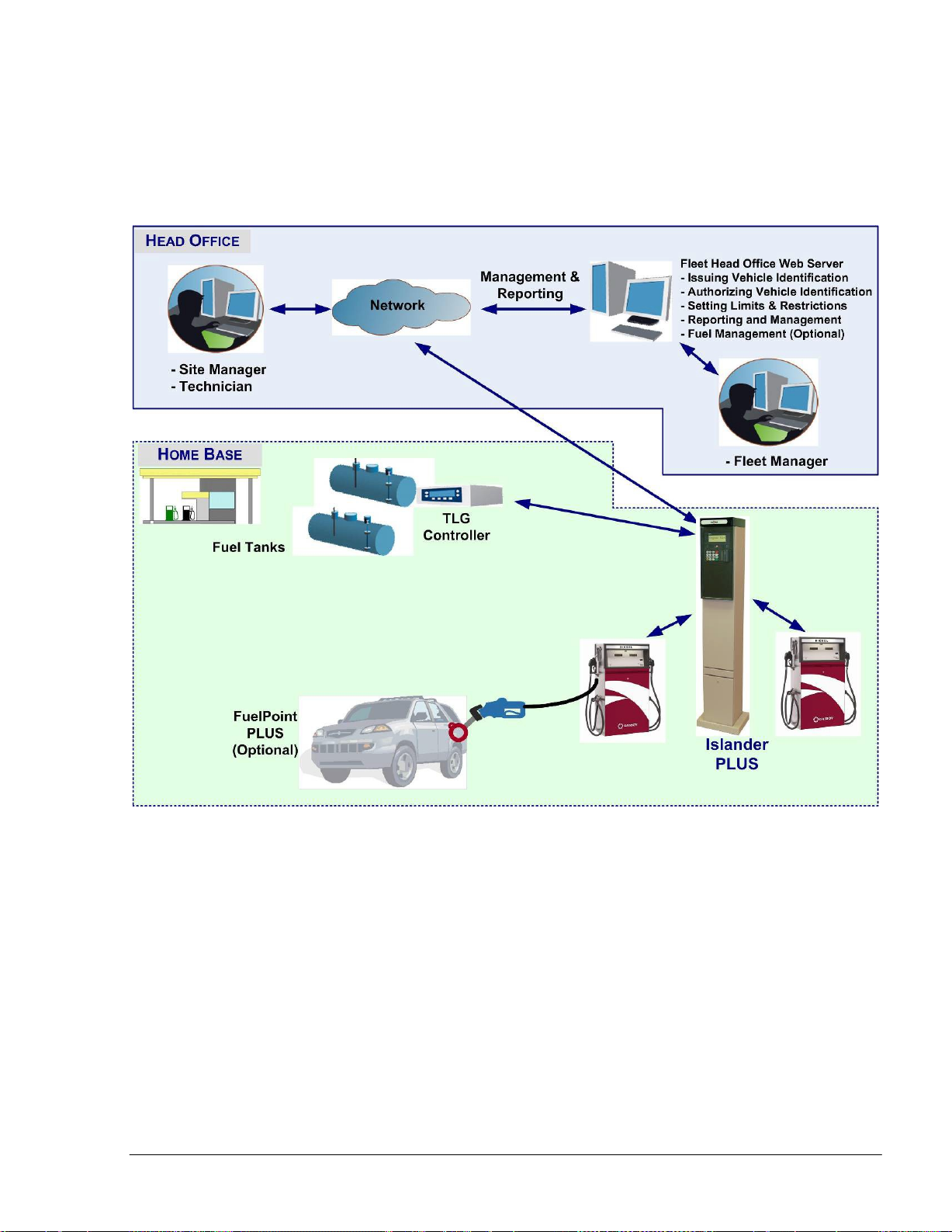
23
SiteOmat Setup and Mainte nance Manual – MDE 4817G
•
Interface to Head Office Systems - The system has an interface for authorization and
for sending transaction to 3rd party head office/ SiteOmat Fleet Head Office using a
single export format (Web Services).
Figure 1-1 – Islander PLUS in Home Base Station - General Configuration Diagram
Page 28

24
SiteOmat Setup and Mainte nance Manual – MDE 4817G
1-2.3. Internal Communication Alternatives
OrCU can communicate with the other modules in the Island Controller system over:
a. TCP/IP Ethernet over CAT5e wires (some modules require the CommVerter Module as the
interface)
b. RS-485 links (segmentation to several links is available)
c. 8 Port CommVerter system
1-2.4. External Communication Alternatives
Communication with external management and data processing systems, for reports and
clearinghouse, can be provided by:
a. Direct - Ethernet or RS-232
b. ADSL/ISDN Modem
c. Dial-Up Modem (not recommended)
d. GPRS, Cellular modem.
The communication equipment depends on the station configuration. See details in section 9.
1-2.5. Data Access Methods
OrCU is a web server over an SQL transaction database. It uses a secured link with several levels
of authentication. Logging into the SiteOmat is done with a standard browser from any PC and a
static IP address. Data is available in real time using pre-defined active forms.
Real-time data is available via an on-line connection, a dedicated line or Internet/Intranet (Secured)
link. The Station Controller system with SiteOmat enables real-time monitoring of a vehicle
refueling process including Volume, Price and all vehicle details.
The SiteOmat Station Controller supports exporting (transactions) and importing (Negative/Positive
lists) data using a pre-defined format.
1-3. ORCU
Orpak Controller Unit (OrCU) is a complete forecourt controller with its own embedded operating
system. The unit consists of an embedded hardware platform with a solid state Flash hard disk,
Real Time Clock (RTC) with back up, along with surge suppressors for transient and noise
immunity. It also includes power fail recovery mechanisms.
OrCU features two separate and isolated networks (TCP/IP over Ethernet). One network links the
Islander PLUS system components. The second network is intended for external remote
communication (Head Office, 3
rd
party systems). This network is protected by SSL security.
Page 29
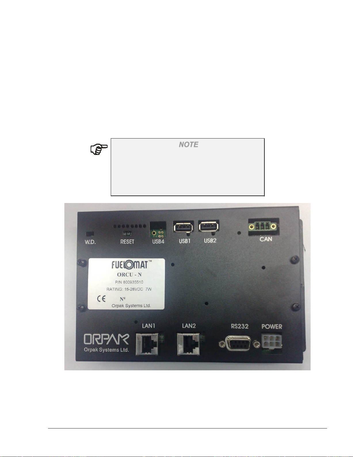
25
SiteOmat Setup and Mainte nance Manual – MDE 4817G
OrCU includes a Security Access Module (SAM) for enhanced data protection and safe security key
storage (Triple DES encryption). OrCU includes a built-in server for Web access through Internet
Explorer 7.0 or higher.
OrCU includes the following communication ports:
•
LAN 1 / LAN 2 for TCP/IP over Ethernet
•
RS-232 ( DB9-female ) for serial communication
•
The other ports (CAN, USB) are currently not in use
NOTE
This note is relevant for the Islander PLUS system
only:
The connection (RS-485) to the optional printer is
done through the OrPT device. OrPT is connected to
the OrCU via LAN.
Figure 1-2 - OrCU - General View
Page 30

26
SiteOmat Setup and Mainte nance Manual – MDE 4817G
1-4. SYSTEM WORKFLOW – EXAMPLES
1-4.1. General
This section provides examples of different operational workflow, refueling, scenarios for selfservice at the Home Base Station. These examples are a function of the payment and transaction
devices available in each Station Controller system.
1-4.2. Refueling Scenario with FuelPoint PLUS
A motorist stops for fuel at the station. His authorization device for the fueling transaction is a
vehicle identification unit (VIU) mounted in his car. The client lifts the nozzle and inserts it into
the car’s fuel inlet.
The VIU information is automatically read and sent to the Site Controller (OrCU) for
authentication and approval. Upon approval the fueling transaction starts, once refueling is
completed, the motorist replaces the nozzle back to pump. At this point the transaction data is
kept internally. Data is periodically transferred to the Fleet Head Office (FHO) for future billing.
1-4.3. Refueling Scenario with Magnetic Cards
A motorist stops for fuel at the station. His authorization device for the fueling transaction is a
magnetic card. The client swipes the card through the magnetic card reader on the payment
terminal.
The magnetic card information is read and sent to the Site Controller (OrCU) for authentication
and approval. The client lifts the nozzle and inserts it into the car’s fuel inlet. Upon approval,
the fueling transaction starts, once the refueling is completed, the motorist replaces the nozzle
back to the pump. At this point the transaction data is kept internally. Data is periodically
transferred to the Fleet Head Office (FHO) for future billing.
During the authorization process the motorist may be prompted to enter more data to the
transaction (PIN code, Odometer, Vehicle No., Etc.). This is done by manually entering the
information using the payment terminal keypad.
1-4.4. Refueling Scenario with 2 devices (2 stage
authorization)
A motorist stops for refueling at the gas station. His authorization devices for the refueling
transaction include any two devices. One represents the vehicle and the other represent the
driver (e.g. two cards, two tags, card and tag, card and manual entry, etc.). The refueling
scenario for each device is the same as with magnetic cards (see above). For each device, the
motorist may be requested to add more relevant data to the transaction (PIN for the driver,
Odometer recording for the vehicle, etc.). The OrCU opens the dispenser for refueling only after
successful authorization of the two devices.
For all options above, the motorist may print a transaction ticket from the Islander PLUS printer
(optional).
Page 31

27
SiteOmat Setup and Mainte nance Manual – MDE 4817G
1-5. MANUAL STRUCTURE
This manual comprises the following sections:
Section 1: General Description
This section provides a general description of the fleet fueling system in general, and the SiteOmat
Station Controller in particular.
Section 2: Pre-Setup Information
This section provides the preliminary information required for configuring the SiteOmat software,
such as defining the devices and communication buses in the system.
Section 3: OrCU Administration Screen
This section provides instructions for setting the initial Controller configuration in the OrCU
Administration Screen
Section 4: Installation Wizard for Station Basic Configuration
This section provides instructions for using the wizard to set the main features of the Controller.
Section 5: Specific Parameters Setting
This section provides instructions for setting specific parameters required for completing the station
setup process.
Section 6: Advanced Setup Procedures - Global Parameters
This section provides the advanced setup instructions for the Controller global parameters.
Section 7: Advanced Setup Procedures - Forecourt Parameters
This section provides the advanced setup instructions for the Controller peripherals and devices.
Section 8: Maintenance
This section provides the technician comprehensive system maintenance description and
instructions including managing file locations, software installation, system operation, backup and
recovery, databases, log files, FCC monitor utility program and Linux commands.
Section 9: OrCU External Communication
This section describes the communication alternatives between SiteOmat and FHO.
Section 10: Glossary
This section provides a glossary of abbreviations used in this manual.
Appendices A to C: Site Survey Forms
These appendices contain survey forms for listing and defining the equipment installed in the
station, provided in order to enable planning and setup of the Controller system.
Appendix D: How to Open ZIP or RAR Files
This appendix provides instructions for extracting compressed files.
Appendix E: Setting the IP Address
Page 32

28
SiteOmat Setup and Mainte nance Manual – MDE 4817G
This appendix provides instructions for setting the IP address on a PC
Appendix F: Weight and Measures Security Plug
This appendix provides instructions for installing the Weight and Measures Security Plug in Gasboy
Site Controllers.
1-6. USING THIS MANUAL
This manual includes comments to enhance the text, in order to draw the reader’s attention to
important issues. The comments are accompanied by symbols for ease of reference. The following
comment types are used:
WARNING
An operating procedure, practice, etc., which if not
correctly followed, could result in injury or loss of
life.
CAUTION
An operating procedure, practice, etc., which if not
strictly observed, could result in damage to, or
destruction of equipment.
TIP
A useful guidance intended to help use the system in
a more efficient way.
NOTE
A relevant and important comment.
INSIGHT
More detailed technical/ functional information
regarding relevant issues.
Page 33

29
SiteOmat Setup and Mainte nance Manual – MDE 4817G
1-7. REFERENCES
For additional and complementary information regarding Gasboy’s home base solution, please refer
to the following manuals:
• Islander PLUS installation Manual, Document No. MDE-4811
• CFN PLUS installation Manual, Document No. MDE-4813
• Fuel Truck Controller installation Manual, Document No. MDE-4814
• Wireless Gateway installation Manual, Document No. MDE-4815
• SiteOmat Station Controller User’s Manual, Document No. MDE-4818
• OrPT User’s Manual, Document No. MDE-4819
• 8-Port CommVerter User’s Manual, Document No. MDE-4820
• FHO installation and setup guide Document No. MDE-4821
• Fuel Point PLUS Installation and Configuration Manual, Document No. MDE-4851
Page 34

30
SiteOmat Setup and Mainte nance Manual – MDE 4817G
SECTION
PRE-SETUP
INFORMATION
2
2-1. GENERAL
This section provides the preliminary information required for configuring the SiteOmat software.
This procedure consists of defining the devices and communication buses in the system, necessary
for the installation and setup of SiteOmat.
2-2. SETUP DEFINITION INFORMATION
2-2.1. Required Setup Information
The Controller system – Islander PLUS, CFN PLUS, and Fuel Truck Controller - is provided with
the SiteOmat software already installed in OrCU.
Therefore, the setup procedures consist of defining the different buses or communication channels
that transport data to/from the controller systems.
Then the devices connected to the Controller and their operating attributes must be defined. These
devices range from pumps, payment devices up to the optional printer.
2-2.2. Required Setup Information – Example
Figure 2-1 shows the required setup information for the pump server and a pump.
First, the user is required to define the pump server bus that transports data to/from the OrCU. This
Pump Server is an internal software module within the OrCU. The user is required to enter its IP
address, port and frame. This information is provided in Table 2-1 and Table 2-2.
Page 35

31
SiteOmat Setup and Mainte nance Manual – MDE 4817G
Figure 2-1. Setup Requirement – Example (Pump)
2-3. SITE SURVEY
Prior to any setup procedure, perform a site survey. See appendices A to C.
Page 36

32
SiteOmat Setup and Mainte nance Manual – MDE 4817G
(FCC)
CommVerter
WGT Master
192.168.1.170
192.168.1.170
N/A
N/A
WGT 192.168.1.171
192.168.1.171
192.168.1.190
3001-3008
OrPT 192.168.1.211
192.168.1.211
192.168.1.230
3000
Receipt Printer
192.168.1.211
192.168.1.211
192.168.1.230
3485
2-4. ETHERNET NETWORK ADDRESSES
2-4.1. Network Addresses for Controller Internal Devices
Table 2-1 lists the IP addresses for the internal devices in the Controller system.
Table 2-1. Network Addresses for Controller Devices
Device
OrCU Ethernet 0
8 Port
Default IP Address
192.168.1.104
192.168.1.111
Starting IP
Address
192.168.1.104
192.168.1.111
Ending IP
Address
192.168.1.130
TCP Ports
3001-3008
Where:
•
Default IP is the IP addresses defined prior to delivery
•
Starting IP Address is the first IP number in the range allocated for the device
•
Ending IP Address is the last IP number in the range allocated for the device
For example, the range to the OrPT is 211 to 230 or a maximum of 20 OrPT devices in the station.
NOTE
IP addresses can be modified according to local
network requirements.
2-4.2. Serial Addresses for Controller Devices
Table 2-2 lists the setup addresses of devices, required for the configuration of the Controller.
Page 37

33
SiteOmat Setup and Mainte nance Manual – MDE 4817G
Device
Default Address
Starting Serial
Ending Serial
OrTR (Orpak Tag Reader)
0x61
0x61
0x69
OrPT (Orpak Payment Terminal)
0x46
0x46
N/A
Printer
0x70
0x70
0x74
Journal Printer
N/A
0x1
N/A
Wireless Gateway
0x31
0x31
N/A
Table 2-2. Serial (HEX) Addresses for Devices
Address
NOTE
The HEX address configured in the controller must
match the device HEX address. Otherwise, the
device is not loaded.
An example of address configuration for Islander PLUS and CFN controllers is displayed in
Figure 2-2 and Figure 2-3 respectively; examples for an Extension Box and ICR PLUS in
Figure 2-4 and Figure 2-5.
Address
Page 38

34
SiteOmat Setup and Mainte nance Manual – MDE 4817G
Optional
PLUS
ICR
---- -
-.,
System
Islander PLUS
192.168
.1.
212
Address
-----
WGT
Remote
console
Head
Office
OrPT
.----
1'92.168.1.10
5
port
switch
192. 111
sub)
MPI-C
MPI-C
1-1
-
(sub)
2 1
Dispensers
HID
reader
nS450
0--
t
I
0
1
MPI-C
(
2-1
I
02
t
Probes
Figure 1-1. System Address Example- Islantkr PLUS
+
10.0.0.1
_
IP
Router
OrCU
Page 39

35
SiteOmat Setup and Mainte nance Manual – MDE 4 817G
I
tt
Optional
ICR
PLUS
---- -
--,
System
192.168.1.21:2- -
CFN
Address
PLUS
Optiona
OutdOJ
WGT
o
--
l
r
Remote console
Head
Office
-
I
192.
168
.1.17(
,---- -
1'92.168.1.104
n.s
...
;o
o--
RS-232
I
MPI-C (sub)
2·1
MPI-C
1-
1--
OrCU
I
02
Probes
I
0
1
Figure 1-3. System Address
MPI-C .
1-1
Example-
Dispensers
CFN
_
PLUS
Page 40

36
SiteOmat Setup and Mainte nance Manual – MDE 4817G
Svstem Ad
Extension Box
dress
Optiona
l
Outdoo
r
WGT
I
192.1
68.
1.171
Isl
ander PLUS
or
CFN
PLUS
5
port
switch
MPI-C
1--
1-
192. 12
Oi$pensers
_
_
Example-
Extension
Box
MPI-C (sub)
2·1
MPI-C .
1-1
Figure 1-4. System Address
Page 41

37
SiteOmat Setup and Mainte nance Manual – MDE 4817G
System
ICR
Address
PLUS
OrPT
192.
168.1.171
HID reader
WGT
MPI-C
1
-1-
5
port
switch
192. .112
Islander
CFN
PLUS
or
PLUS
MPI-C (sub),
2-1 -
_
MPI-C(sub). --------
2-1 -
Dispensers
Figure 1-5. System Address
Example-
ICR
PLUS
Page 42

38
SiteOmat Setup and Mainte nance Manual – MDE 4817G
2-5. NAVIGATION NOTES
The user-interface of the SiteOmat application may display common messages during operation.
These messages are common to several situations, and they are provided below for general
information.
2-5.1. Not Saving Change
If data has been changed in a dialog box or a screen and the user tries to navigate away from it
without saving the changes, the following message is displayed (see Figure 2-6).
Figure 2-6. Cancel Warning Message
2-5.2. Saving Data
When saving data or performing an operation, the following message appears (see Figure 2-7).
Figure 2-7. Processing Message
Once the processing has successfully completed, the screens are updated to reflect the changes.
2-5.3. Errors
In all setup and definition dialogs, a validity check is made when clicking on New or Modify. The
first check is for duplicate definition of the same device. For the same device type (printer, bus,
etc.) the name must be unique. Attempting to define the same name displays the Operation failed
error message (see Figure 2-8).
Page 43

39
SiteOmat Setup and Mainte nance Manual – MDE 4817G
Figure 2-8. Same Name Error Message
IP and port pairs must be unique (see Figure 2-9).
Figure 2-9. IP Port Error Message
On the same bus, a 485 address cannot be defined twice (see Figure 2-10).
Figure 2-10. Device with Same Address Error Message
If a device is used in the setup, it cannot be deleted. An error message is displayed (see
Figure 2-11).
Figure 2-11. Cannot Delete Message
2-5.4. Confirmation
When trying to delete data, the following confirmation message appears (see Figure 2-12).
Page 44

40
SiteOmat Setup and Mainte nance Manual – MDE 4 817G
Figure 2-12. Confirmation Message
2-5.5. Success
In cases where an action has successfully completed, the success message is displayed (see
Figure 2-13).
Figure 2-13. Operation Successful Message
2-6. CONFIGURATION AND SETUP PROCEDURES
All setup steps are summarized into the following list, guiding the user through all the
installation stages, more details on each step are provided in the following chapters:
1. Open the door on the Islander PLUS or CFN PLUS (Controller)
2. Connect the pumps (or pump simulator) to the controller
3. Check the connections
4. Power on the pumps
5. Connect the controller to power and turn power on
6. Connect the technician PC to any free connector on the 5 port switch with an
Ethernet cable (CAT5E)
7. Set the technician's PC IP address to 192.168.1.10 (see APPENDIX E)
8. Open Internet Explorer 7.0 or higher on the connected computer
Page 45

41
SiteOmat Setup and Mainte nance Manual – MDE 4817G
9. Set the peripherals communication parameters in the 8-port CommVerter (see
details in MDE-4820)
10. If needed, configure the controller operating system in the OrCU
Administration screen (see section 3)
11. Browse to the SiteOmat Wizard and setup the station (see section 4)
12. Set specific station parameters (See section 5)
13. For advanced settings: change global default settings (See section 6) or
forecourt devices default settings (See section 7)
14. Save the settings and Reload the system
15. Backup (See section 8-3)
16. In cases where mechanical pumps are in use, put the channel in Bypass and
check that the pump refuels (see below)
17. Remove the channel from Bypass
18. Verify that the MPI-C Inuse LED is on when taking out the nozzle
19. Verify that the MPI-C pulser LED is blinking when fueling
20. Use the status screen to produce a full transaction by clicking on the pump
icon
21. Verify that the decimal points are identical to those in the pump, set the
SiteOmat accordingly and click Reload
22. Go to Fleet Management and add a testing fleet and a vehicle tag/card/key
(use Acquire if installing Islander PLUS). Do not use a real fleet code. This
device should not be added to the Head Office in later steps
23. Check the refuel process using the authorization device defined for testing
24. Get advise from the IT manager on the external IP address of the controller
for external communication
25. Got to the Administrator screen and change "eth1" accordingly (see
paragraph 9-3.3)
26. In Head Office:
a. Verify that the PC complies with the specifications indicated in the
manual
b. Check the connection to internal Intranet or External Internet (get
help from IT)
c. Install the HO
d. From the HO computer, check the connection to the Controller (use
"PING" command or browse to it)
e. Set the HO global parameters
f. Set the products
Page 46

42
SiteOmat Setup and Mainte nance Manual – MDE 4 817G
g. Set the Controller and wait for synchronization success in the station
status row (it may take a few minutes)
h. Set fleets and devices
2-7. BYPASS FEATURE FOR MECHANICAL PUMPS
Site Controllers configuration for mechanical pumps include bypass switches – a switch per
dispenser (apart from TopKat PLUS which requires adding an external bypass switch, P/N
813104450 to the existing distribution board). These should be used in cases of system malfunction
to enable refueling. The switch is connected to Line (high voltage cable) and to the controller (low
voltage wires) so as to provide indication on bypass state.
While the system is in Bypass state, SiteOmat keeps capturing the total dispensed from the pumps
and generates an event displayed in Event Viewer screen.
Page 47

43
SiteOmat Setup and Mainte nance Manual – MDE 4817G
SECTION
3
OrCU ADMINSTRATION SCREEN
3-1. GENERAL
The SiteOmat Station Controller is factory set with the general configuration required for its proper
operation. However, settings may be modified in the OrCU Administration screen (see
Figure 3-2) according to location or network specifications.
3-2. TECNICIAN PC SOFTWARE REQUIRMENTS
The following software must be installed on the technician's PC prior to the controller setup
process:
1. OS – Microsoft Windows 2000/XP/2003
2. Microsoft Internet Explorer 7 or a higher version.
3. Sun Microsystems Java application (Can be downloaded from http://Java.com
3-3. INITIAL SETUP PROCEDURES
To set the initial Controller configuration, proceed as follows:
1. Follow steps 1 to 10 described in section 2-6 above
2. Turn on the browser and type the default IP address for the OrCU Administrator screen:
o http://192.168.1.104:8090
)
o https://192.168.1.104:8090 (for BSP ver. 1.08 SP 9 and up)
The login dialog box appears (see Figure 3-1)
NOTE
For cases where the OrCU default IP was changed or
the IP is unknown, see paragraph 8-12.
Page 48

44
SiteOmat Setup and Mainte nance Manual – MDE 4817G
Figure 3-1. Login Dialog Box
3. Enter the User name (Default: admin) and Password (Default: admin)
4. Click on the OK button. The OrCU Administrator Home screen appears (see Figure 3-2)
Figure 3-2. OrCU Administrator –Home Screen
The screen displays status data, containing several parameters described in Table 3-1 and
navigation buttons redirecting to System Information, Setup and Install screens described in the
following sections.
Page 49

45
SiteOmat Setup and Mainte nance Manual – MDE 4817G
Element
Description
LAN1 IP
LAN 1 IP Address. Default: 192.168.1.104
LAN2 IP
LAN 2 IP Address. Default: 10.0.0.1
PPP0 IP
IP Address assigned to dialup or GPRS
Date/Time
The controller date and time as defined by the
OS up time
Time elapsed since the last OS reboot.
OrCU FW Version
Currently installed OS version.
OrCU S/N
OS serial number.
SiteOmat Version
Currently installed SiteOmat version.
OrData Version
Currently installed OrData version.
Table 3-1. OrCU Status Screen Elements
connections.
user.
3-4. SYSTEM INFORMATION
The System Information screen (see Figure 3-3) displays the following maintenance data:
•
Total Memory, Used Memory and Free Memory
•
Disk Statistics
•
Processes
•
FCC, BOS and PAIS Thread Counter
The screen includes the following features described below:
•
Versions
•
Largest Files
•
Mini Terminal
•
Reboot Unit
Page 50

46
SiteOmat Setup and Mainte nance Manual – MDE 4817G
Figure 3-3. System Information Screen
3-4.1. Versions Screen
Click on the Versions button to display the Versions screen (see Figure 3-4).
This screen displays currently installed Pump Server, PAIS and OrData versions.
Clicking on the Log button opens a dialog box containing a history log of version updates.
Figure 3-4. Versions Screen
Page 51

47
SiteOmat Setup and Mainte nance Manual – MDE 4817G
3-4.2. Largest Files Screen
Click on the Largest Files button to display the Largest Files screen (see Figure 3-5).
This screen displays a list of all system files which are larger than 1Mb.
Figure 3-5. Largest Files Screen
3-4.3. Mini Terminal Screen
Click on the Mini Terminal button to display the Mini Terminal screen (see Figure 3-6).
This screen enables users to run simple Linux commands.
Type the command in the lower part of the screen and click on the Execute button to receive the
output in the upper part.
Page 52

48
SiteOmat Setup and Mainte nance Manual – MDE 4817G
Figure 3-6. Mini Terminal Screen
3-4.4. Reboot Unit
The Reboot Unit button on the System Information screen reboots the Controller, as required after
a component is installed/updated in order to apply the changes.
A warning message appears (see Figure 3-7). Click OK to proceed.
Figure 3-7. Unit Reboot Warning Message
3-5. SETUP SCREENS
The Setup section enables the user to configure the following options described below:
•
Networking
•
Time
•
Password
•
Serial/Modem
•
UPS
Page 53

49
SiteOmat Setup and Mainte nance Manual – MDE 4817G
3-5.1. Networking
SiteOmat Station Controller has a default IP address, which may be changed to suit the
requirements of the local network.
NOTE
The default IP address at LAN 1 is 192.168.1.104.
To set up the network, proceed as follows:
1. Click on the Networking navigation button
2. Follow the steps described in paragraph 9-3.3
3-5.2. Time
To adjust the Controller’s date and time to match the regional date and time, proceed as follows:
CAUTION
Verify that all station activities are ceased before
1. Click on the Time navigation button
modifying clock settings.
2. The Time Setup screen appears (see Figure 3-8). Enter the Date and Time in the
corresponding text boxes
3. Select the Time Zone from the drop-down list
4. Click on the Change time settings button to save the changes
5. Reboot the system (see paragraph 3-4.4) to apply the changes
Page 54

50
SiteOmat Setup and Mainte nance Manual – MDE 4817G
Figure 3-8. Time Setup Screen
3-5.3. Password
To change the password to the OrCU Administration site, proceed as follows:
1. Click on the Password navigation button
2. The OrCU Password screen appears (see Figure 3-9) Enter the selection in the New
Password and Confirm Password text boxes
3. Click on the Change Password button to save the changes
Figure 3-9. OrCU Password Screen
3-5.4. Serial/ Modem
To set up the serial port connection, proceed as follows:
1. Click on the Serial/Modem navigation button. The OrCU Serial/Modem Settings screen
appears (see Figure 3-10)
Select the option Use port for External Devices in cases where the serial port is connected
to the TLG, or to the Weight & Measures Security Plug (refer to APPENDIX F)
2. In cases where the serial port is used for modem connection, follow the instructions
provided in paragraph 9-4.2
Page 55

51
SiteOmat Setup and Mainte nance Manual – MDE 4817G
Figure 3-10. Serial/Modem Settings Screen
3-5.5. UPS
This screen allows users to connect the SiteOmat to an UPS (Uninterruptable Power Supply)
system. In cases where a prolonged power interruption has occurred, the BSP properly shuts
down all applications and stops the FCC. When power is restored, the BSP restarts the system
automatically.
Currently, only one UPS vendor is supported: ARTronic 1KVA & 3KVA.
To set up the UPS, proceed as follows:
1. Click on the UPS navigation button. The OrCU UPS Setup screen appears (see
Figure 3-11)
2. Define the following parameters (described in Table 3-2) using the drop-down lists and
text boxes
Page 56

52
SiteOmat Setup and Mainte nance Manual – MDE 4817G
Parameter
Definition
Company
UPS manufacturer.
Model
UPS model name.
Retries
Number of connection retries to the UPS
Time Left
Estimated remaining UPS power-time prior
Check Interval
Frequency of remaining UPS power-time
IP Address
UPS static IP address.
Log enabled
This option enables to write UPS logs into
Figure 3-11. UPS Setup Screen
Table 3-2 UPS Setup Parameters
3. Click Save Changes to save the changes, or
prior to controller shutdown.
to controller shutdown.
checks.
var/log/UPSMonitor.log.
click Apply Changes to apply the changes, or
click Default Settings to restore the default OrCU UPS settings
Page 57

53
SiteOmat Setup and Mainte nance Manual – MDE 4817G
3-6. INSTALLATION SCREENS
The Installation section enables the user to install the following application and components
described below:
•
SiteOmat
•
OrData
•
Pump Server
•
PAIS
•
Operating System
3-6.1. SiteOmat
As a rule the SiteOmat is pre-installed, at the factory level, in the OrCU. However, whenever
required, SiteOmat can be installed in the OrCU in the station.
NOTE
Before installing SO versions 6.4.42 and up, upgrade
BSP (OrCU Operating System) to version 1.08 SP 9
(see Section 3-6.5).
From this version on, OrCU Administrator setup
web connects to OrCU unit using a secure link
(HTTPS).
Prior to installing SiteOmat, proceed as follows:
1. Obtain the SiteOmat installation files. The SiteOmat installation file is named as:
FCC_ORCU_dd_mm_yy
Where: dd_mm_yy is the date the files were built, and a_b_ccc is the version.
a_b_ccc.exe
For example: File FCC_ORCU_28_02_11 6_3_300 was built on 28/02/11, version
number is 6.3.300.
In cases where upgrading SiteOmat to a later version, verify the following:
CAUTION
These procedures, if not strictly observed, could
result in damage to the setup and database of the
system.
1. All station activities are stopped
2. All the transactions have been transferred to the Head Office
3. FCC was stopped, by clicking on the Stop button on the Sys Commands screen (see
paragraph 8-2)
4. Station DB was back-upped (see paragraph 8-3)
Page 58

54
SiteOmat Setup and Mainte nance Manual – MDE 4817G
5. If the controller is configured for mechanical pumps, verify that the Weight & Measures
security plug is installed. The following reminding message appears (see Figure 3-12)
Click OK to proceed.
Figure 3-12. W&M Security Plug Message
Before upgrading SiteOmat, please contact your
agent for the latest version.
NOTE
To install the SiteOmat, proceed as follows:
1. Click on the SiteOmat navigation button. The OrCU Install SiteOmat screen appears (see
Figure 3-13)
Figure 3-13. Install SiteOmat Screen
2. Click on the Browse button and select the SiteOmat installation file
3. Click Upload
4. Wait until the upload is finished (this process may take few minutes)
Page 59

55
SiteOmat Setup and Mainte nance Manual – MDE 4817G
5. Click Upgrade to update SiteOmat to the latest version, or click Install to perform a
fresh installation
CAUTION
Clicking on Install, deletes all setup and database if
a previous version is already installed. A warning
message appears (see Figure 3-14).
Figure 3-14. Installation Warning Message
6. Click OK. The installation progress is displayed. Wait until the installation is finished
7. Reboot the system (see paragraph 3-4.4)
3-6.2. OrData
To install the OrData application for a station interfacing with DataPass PLUS devices which
recognize and store displays On-Board Diagnostics error codes, proceed as follows:
1. Click on the OrData navigation button. The OrCU Install OrData screen appears (see
Figure 3-15)
Figure 3-15. Install OrData Screen
2. Click on the Browse button and select the OrData installation file
Page 60

56
SiteOmat Setup and Mainte nance Manual – MDE 4817G
3. Click Upload
4. Wait until the upload is finished (this process may take few minutes)
5. Click Upgrade to update OrData to the latest version, or click Install to perform a fresh
installation
CAUTION
Clicking on Install, deletes all setup and database if
a previous version is already installed. A proper
warning message is displayed.
6. Reboot the system (see paragraph 3-4.4)
3-6.3. Pump Server
To install the Pump Servers needed for interfacing with the specific pumps deployed in the station,
proceed as follows:
1. Click on the Pump Server navigation button. The OrCU Install Pump Servers screen
appears (see Figure 3-16)
Figure 3-16. Install Pump Server Screen
2. Click on the Browse button and select the Pump Server installation file
3. Click Upload
4. Wait until the upload is finished (this process may take few minutes)
5. Click Install to install the Pump Server package
6. Reboot the system (see paragraph 3-4.4)
Page 61

57
SiteOmat Setup and Mainte nance Manual – MDE 4817G
3-6.4. PAIS
To install the driver for a third party clearing system, proceed as follows:
1. Click on the PAIS navigation button. The OrCU Install PAIS screen appears (see
Figure 3-17)
Figure 3-17. Install PAIS Screen
2. Click on the Browse button and select the PAIS installation file
3. Click Upload
4. Wait until the upload is finished (this process may take few minutes)
5. Click Install to install the PAIS driver
6. Reboot the system (see paragraph 3-4.4)
3-6.5. Operating System (BSP)
To upgrade a previously installed controller operating system, proceed as follows:
1. Click on the Operating System navigation button. The OrCU Install Operating System
(BSP) section is displayed (see Figure 3-18)
2. Click on the Browse button and select the BSP installation file (the file is named as
BSPX.XXSPXX)
Page 62

58
SiteOmat Setup and Mainte nance Manual – MDE 4817G
3. Click Upload
Figure 3-18. Install Operating System (BSP) Screen
CAUTION
Updating the BSP service pack, deletes previous
BSP setup. A warning message appears (see
Figure 3-19).
4. Click OK
Figure 3-19. BSP Service Pack Upgrade Warning Message
5. Reboot the system (see paragraph 3-4.4)
3-6.5.1. BSP Upgrade Schema
BSP upgrade may require installation of previous versions first, depending on the currently installed
version and service pack, as shown in Figure 3-20.
Page 63

59
SiteOmat Setup and Mainte nance Manual – MDE 4817G
Figure 3-20. BSP Upgrade Schema
Click on the Rollback button (see Figure 3-18) to return to the previous SP version. For example if
SP5 was upgraded to SP9, Rollback option will install SP8.
Page 64

60
SiteOmat Setup and Mainte nance Manual – MDE 4817G
SECTION
SETUP
WIZARD
4
4-1. GENERAL
The Setup Wizard helps the technician to set up the station, guiding the user through the process
and initializing most of the system's setup parameters automatically. Once the Wizard is finished,
most standard stations are ready for fueling and no additional settings are required.
The wizard also allows selection of predefined templates for fully configuring the system according
to stations with similar characteristics. If a predefined template is selected, the wizard consists of
pages that contain specific station data only.
After the Wizard is finished, the Main Setup screen is displayed, enabling the user to complete the
process, or to change to the Advanced Mode in order to define more complex forecourt
configurations.
Rerunning of the wizard is allowed; however, the existing setup data is overwritten (fuelling data
such as transactions are not deleted). In such cases, the user is provided with a proper warning.
The Cancel button in each screen enables the user to cancel the process and return to the main
Setup window. In this case, no data is saved, and no changes are made to the system. The user is
alerted that all changes are lost if the process is cancelled in the middle.
In cases where the configuration is done without the wizard, the logic of the setup procedure should
be from top to bottom. That is, first define the physical configuration: Station Parameters, Alarms
and Communication (FCC) channels, etc. Once these parameters have been set, define the Setup
parameters. This Setup includes first the buses or communication channels, then the definition of
peripherals such as printers and tag readers. Setting the system in this order ensures the definition of
all the existing building blocks for each component.
In cases where the Wizard is rerun after settings
were changed from SiteOmat Setup screens, the
Wizard may not reflect the changes made (i.e.
settings not supported by the Wizard).
NOTE
Page 65

61
SiteOmat Setup and Mainte nance Manual – MDE 4817G
4-2. SOFTWARE REQUIREMENTS
MS Silverlight plug-in must be installed on the PC prior to running the Wizard.
The plug-in can be downloaded from: http://www.microsoft.com/getsilverlight/GetStarted/Install/Default.aspx
Silverlight downloading and installation is described in 4-3.1
4-3. ACCESSING THE WIZARD
To access the wizard, proceed as follows:
1. Open Internet Explorer 7.0 or higher
2. Type the default SiteOmat IP address:
https://192.168.1.104/
3. Login as Administrator. At initial startup, default username is Admin and default password
is Admin
NOTE
When first logging in, the administrator is required
to change the password in order to meet the
customer's security needs.
4. On first installation, when no previous setup exists and Microsoft Silverlight plug-in has
already been installed, the first page of the SiteOmat Setup Wizard (see Figure 4-10)
appears. In cases where Silverlight plug-in is missing, the Wizard displays a download link
(see Figure 4-3). If a previous setup is found, the Setup screen appears (see Figure 4-1). In
this case, click on the Wizard button to open the Wizard
Page 66

62
SiteOmat Setup and Mainte nance Manual – MDE 4817G
Figure 4-1. Setup Screen
5. Since previous setup is overridden by the wizard, in cases where a previous setup is found,
the following warning message appears (see Figure 4-2)
Figure 4-2. Setup Wizard – Setup Override Warning Message
4-3.1. Microsoft Silverlight Installation
In cases where the Microsoft Silverlight plug-in for IE browser has not been installed and the
technician PC is connected to the internet, the Wizard displays a download link (see Figure 4-3)
Page 67

63
SiteOmat Setup and Mainte nance Manual – MDE 4817G
Figure 4-3. Setup Wizard – Microsoft Silverligth Download Link
Proceed as follows:
1. Click on the download link. The following message appears (see Figure 4-4)
Figure 4-4. Microsoft Silverligth Update Message
2. Click on Install now. The File Download message appears (see Figure 4-5) prompting the
user to run or save the installation file (Silverlight.exe)
Page 68

64
SiteOmat Setup and Mainte nance Manual – MDE 4817G
Figure 4-5. File Download Security Warning Message
3. Click Run to start the download. When the download is finished, the browser prompts the
user again to run the installer (see Figure 4-6)
Figure 4-6. IE Security Warning Message
4. Click Run to start the installation. The following message appears (see Figure 4-7)
Figure 4-7. Install Silverlight Message
5. Click Install now. When the installation is finished an installation successful message is
displayed (see Figure 4-8) Click Close
Page 69

65
SiteOmat Setup and Mainte nance Manual – MDE 4817G
Figure 4-8. Silverlight Installation Successful Message
6. The following message appears (see Figure 4-9). Click OK and restart the browser
Figure 4-9. Restart Browser Message
4-4. SETUP WIZARD PROCEDURE
4-4.1. Validation of Parameters
The Setup Wizard validates the various parameters entered throughout the process to ensure proper
configuration. If an erroneous parameter is found, the text box is marked in red color, a tooltip
describes the error and the corresponding error notification is displayed on the status bar on the
bottom of the page. In addition, the Next button is disabled as long as the error is not fixed.
To correct the error, enter a valid value and press the TAB key to refresh the page.
4-4.2. Page 1 - Welcome
This is the first page of the SiteOmat setup wizard (see Figure 4-10). Select the system language
from the drop-down list and click Next to continue.
Page 70

66
SiteOmat Setup and Mainte nance Manual – MDE 4817G
Figure 4-10. SiteOmat Setup Wizard, Page 1
4-4.3. Page 2 – Global Parameters
In this page (see Figure 4-11), enter station and regional data.
Page 71

67
SiteOmat Setup and Mainte nance Manual – MDE 4817G
Figure 4-11. SiteOmat Setup Wizard, Page 2
Proceed as follows:
1. Enter Station Code, Station Name, Address, City
2. Select the Measurement System and the Currency to be used form the corresponding
drop-down lists
3. Select the Date, Date Format, Time and Time Zone
4. Click Next to continue
4-4.4. Page 3 - Forecourt Controller Type
In this page, the user can define the forecourt controller type (see Figure 4-12) as well as additional
peripherals (Extension Boxes or ICR+ units).
NOTE
If the station is part of a network, Station Code must
be unique across the network. This code is used to
uniquely identify the station in the Head Office.
Page 72

68
SiteOmat Setup and Mainte nance Manual – MDE 4817G
Also, the user can define if a printer is available for each selected pedestal.
Figure 4-12. SiteOmat Setup Wizard, Page 3
Proceed as follows:
1. Select the Controller model using the radio buttons
2. Select the Printer Available checkbox if the pedestal includes a printer
3. Select the number of Extension Boxes or ICR+ units (if any) and select the Printer
Available checkbox if the ICR PLUS pedestal includes a printer
NOTES
The system supports a maximum of ten peripherals.
If a higher number is entered, the text box is marked
in red and the Wizard displays the following error
notification: Controller numbers cannot exceed
10.
Page 73

69
SiteOmat Setup and Mainte nance Manual – MDE 4817G
In cases where more than one peripheral is in use,
configure the peripherals' IP (Extension Box and
ICR PLUS factory set default IP is 192.168.1.212)
For further details, please refer to 8-Port
Commverter Operation and Installation Manual, P/N
MDE-4820.
4. Click Next to continue
In cases where the station architecture is identical to an already created template, select the Other,
load from file radio button and click Browse to load the predefined xml file. If no template is
selected, the Wizard displays the following error notification: Must select setup file
Page 74

70
SiteOmat Setup and Mainte nance Manual – MDE 4817G
4-4.5. Page 4 - Forecourt Setting
In this page (see Figure 4-13) the user can select the station's settings described below.
Figure 4-13. SiteOmat Setup Wizard, Page 4
Proceed as follows:
1. Select the number of fueling islands at the station using the Number of isles drop-down list.
This parameter is for informational purposes only
2. Select the Number of pumps from the drop-down list. The pumps number is limited
according to the Controller type and the peripheral controllers in use (if any). The system
supports up to 64 pumps
3. Select the Fuel Point Controller checkbox in cases where the station is equipped with a
vehicle identification system (Fuel Point PLUS)
4. Select This station is connected to Head Office if the system interfaces with 3rd party
head office / SiteOmat Fleet Head Office for authorization and data sending
5. A Zero Transaction is defined as an authorized transaction (fuel is being dispensed) but the
volume retrieved remains zero. Set the allowed number of Zero Transactions before
blocking the pump
6. Companies can allow drivers to manually enter their device number in the OrPT by using
the F3 option. Select the Manual entry mode using the following radio buttons:
Page 75

71
SiteOmat Setup and Mainte nance Manual – MDE 4817G
a. None: Disables manual entry
b. First entry screen only: Allows manual entry only in the first screen of the
authorization process
c. Second entry screen only: Allows manual entry only in the second stage of the two-
stage authorization process
d. Both entry screens: Allows manual entry in both stages.
7. Select This station is an upgrade from older system checkbox in cases where SiteOmat
replaces the Series 1000 legacy system
8. OrPT Beeps function provides sound feedback each time a device is detected. Select the
Allow beeps checkbox to activate the feature and enter the required # of beeps. In cases
where more than one OrPT is installed at the station, it is required to associate the dispenser
to a specific OrPT terminal (please refer to paragraph 7-11)
9. Status Screen Beeps function Provides sound feedback on Status Screen each time a nozzle
is lifted. Select the Allow beeps checkbox to activate the feature and enter the required # of
beeps
10. Click Next to continue
Page 76

72
SiteOmat Setup and Mainte nance Manual – MDE 4817G
4-4.6. Page 5 - Products
In this page (see Figure 4-14) the user can edit station products to fit to local requirements. The
system skips this page if the user has selected a template.
Figure 4-14. SiteOmat Setup Wizard, Page 5
The screen displays a grid with the predefined products. The grid fields are:
a. Code
b. Product name
c. Short Name (Used for reports or export to external systems)
d. Price per unit
All fields in the grid are editable. Nevertheless, the parameters set must be able to cross-reference
with the products in the FHO station configuration.
NOTE
Product Name and Short Name must be unique.
To choose the relevant products for the station, select the Used checkbox (at least one product must
be selected in order to continue, otherwise the Wizard displays the following error notification: At
least one product must be selected). Unchecked products are not displayed on SiteOmat's screens
after the setup is finished.
Page 77

73
SiteOmat Setup and Mainte nance Manual – MDE 4817G
Page 6 - TLG and Tanks
In this page (see Figure 4-15), the user can define the tanks and the external TLG (Tank Level
Gauging) system providing fuel tank information. The system skips this page if the user has
selected a template.
Figure 4-15. SiteOmat Setup Wizard, Page 6
Proceed as follows:
1. Select the TLG type from the drop-down-list. TLG 350/450 is currently available
2. Select the Number of tanks from the drop-down list. For each tank the system opens a line
in the grid
3. Select the Communication Type between the TLG console and the Controller using the
following radio buttons:
a. Serial (RS-232 via 8Port): for RS-232 communication via 8-Port Commverter's IP
b. TCP/IP: for Ethernet connection via external convertor or direct TCP/IP. Enter IP
The tanks grid includes the following fields:
a. Number (for read only)
b. Name
– using last slot (port 3007) RS-232 card
and Port
Page 78

74
SiteOmat Setup and Mainte nance Manual – MDE 4817G
c. Product (selected from the drop-down list including all products previously defined)
d. Capacity (must be higher than zero)
e. TLG Tank Number (by default is equal to the tank number, must be less than or equal to 16)
4. Edit the required fields
5. Click Next to continue
Page 79

75
SiteOmat Setup and Mainte nance Manual – MDE 4817G
4-4.7. Page 7 - Pumps
In this page (see Figure 3-17), the user can define the pumps and configure the connection of the
pumps to the controller, printer and Fuel Point PLUS system. The screen displays a grid with a row
for every pump, according to the number of pumps defined on Page 4.
Figure 4-16. SiteOmat Setup Wizard, Page 7
Proceed as follows:
1. Select the Pump Type from the drop-down list containing all supported pump types.
2. Select the Controller to which the pump is connected from the Connected to Controller
drop-down list containing the available controllers or peripherals as set on Page 3. The
wizard checks for compatibility between Controller and pump types selected and notifies the
user on the following mismatches:
a. You connected MPI pump to controller that do not have MPI slots
b. You connected more MPI than can be on a specific controller
c. Not all pumps are connected to controller
d. You connected more electronic pumps than can be on a specific controller.
3. Enter the Head number, namely the communication protocol address of the pump head, as
defined in the dispenser setup and acquired by the technician (must be less than 64)
Page 80

76
SiteOmat Setup and Mainte nance Manual – MDE 4817G
Pumps with identical Head number cannot be
connected to the same Cluster (IP and Port) on an 8Port Module Card.
NOTES
4. Select the OrPT terminal to be linked to the pump for prompts display from the Connected
to OrPT drop-down list (This setting is optional, the Wizard displays a warning notification
in cases where not all pumps were connected to an OrPT but does generate a validation
error)
5. Set the pump to the Tank the pump is actually connected to (Mandatory setting, if not set
the Wizard displays the following error notification: Select tank for all pumps)
6. Select the Product from the drop down list containing all products in use as defined on Page
5. This field is auto-populated based on tank selection
7. Select the Rate, namely the number of pulses per Liter/Gallon as required for mechanic
pumps setup only, using the drop-down list (10,100,1000)
8. Enter the F.P. Plus logical channel for communication with the controller (if F.P. Plus is in
use, as defined on page 4). Enter a different channel (between 1 and 16) for each pump. The
Wizard provides the user with the following error notifications in cases where an incorrect
value was entered:
a. VIS Channel must be less than 16
b. You connected same VIS channel to two pumps
9. For pumps that support Satellite linked nozzles (two nozzles connected to the same pump
head allowing simultaneous refuel from both sides of a truck), enter the second nozzle F.P.
Plus channel (between 1 and 16 and not previously used)
10. Click Next to continue
NOTE
The Setup Wizard supports one-grade dispensers
only. For other configurations, run the Wizard and
then set up the nozzles on the Main Setup screen
(refer to paragraph 4-5).
Page 81

77
SiteOmat Setup and Mainte nance Manual – MDE 4817G
4-4.8. Page 8 – Payment
Credit Processor
Payment processor in use, selected from the drop-down list
PAIS IP & Port
IP address and port for communication between the internal
Tasks
Number of tasks to be simultaneously handled by the processor
App Log
Enables application logging. Select the Enable checkbox and
Comm Log
Enables Controller – Processor communication logging. Select
Timeout
Defines the waiting time for response from the processor
Card may not be reused
Prevents refueling with the same bank card within the selected
In this page (Figure 4-17), the user can set the SiteOmat connection to a third party clearing system.
Figure 4-17. SiteOmat Setup Wizard, Page 8
Set the various parameters described in Table 4-1 and click Next to continue
Table 4-1. Payment Clearing System Parameters
payment application and the Controller (for view only)
(namely, the number of payment terminals in use in the station)
enter the destination Port
the Enable checkbox and enter the destination Port
Page 82

78
SiteOmat Setup and Mainte nance Manual – MDE 4817G
within
time frame
Pre-authorized amount
Pre-authorizes the card prior to the transaction to the defined
End of Day
Activates the End of Day process – the payment application
Specific – Processor IP &Port
IP address and port for communication between the internal
Product Map
See section 4-4.8.1
amount
returns a list of totals (Total amount, Amounts per card type).
The controller saves the data in the EOD summary.
Select the Daily run enabled checkbox to automatically run the
process on a daily base and set the Time to run daily drop-
down lists.
payment application and the Processor
4-4.8.1. Product Map
This feature enables users to associate the products defined in SiteOmat to the external payment
processor.
Proceed as follows:
1. Click on the Product Map button to open the Product Mapping dialog box (see
Figure 4-18)
2. Select the product from the Product name – code drop-down list containing all products in
use as defined on Page 5
3. Enter the processor's code for the product in the External Code text box
4. Repeat steps 2-3 for each product in use
5. Click Save to save the changes, or Cancel to close the dialog box without saving the
changes
Page 83

79
SiteOmat Setup and Mainte nance Manual – MDE 4817G
Figure 4-18. SiteOmat Setup Wizard – Product Mapping Dialog Box
Page 84

80
SiteOmat Setup and Mainte nance Manual – MDE 4817G
4-4.9. Page 9 – Printer
In this page (see Figure 4-19) the user can define receipts. This page is displayed only in cases
where at least one printer was selected on Page 3.
Figure 4-19. SiteOmat Setup Wizard, Page 9
Proceed as follows:
1. Select the Receipt Template form the list
2. Enter Header and Footer to be added as is to the receipt
3. Click on the Browse button to load a PCX file for a logo printout at the top of the receipt.
The logo should be a monochrome (black and white) PCX file, with a maximum size of 1
KB
4. Click Next to continue
Page 85

81
SiteOmat Setup and Mainte nance Manual – MDE 4 817G
4-4.10. Page 10 – Series 1000 Upgrade
This page (see Figure 4-20) enables the user to define Series 1000 cards/keys authorization
parameters, including Fuel and Limit rules settings. This page is displayed only in cases where the
Series 1000 upgrade option on Page 4 was selected.
Figure 4-20. SiteOmat Setup Wizard, Page 10
Proceed as follows:
1. Enter the Series 1000 station System ID. This parameter serves as Fleet Code for all Series
1000 devices added to the database. The PIN Key is currently not applicable.
2. Edit the Limit Cut Off Quantity column in the Product Limit Table: Enter the fuel
quantity allowed per transaction to match Series 1000 Limitation Codes. These constitute a
single Limit Rule added to the database and applied to the Fleet devices
3. Edit the Product Authorization Table, selecting the Allowed Product Code drop-down
lists which contain the product codes defined on Page 5. Select all products permitted (each
row in the table defines a specific code) to match Series 1000 definitions. These constitute a
single Fuel Rule added to the database and applied to the Fleet devices
4. Click Next to continue
Page 86

82
SiteOmat Setup and Mainte nance Manual – MDE 4817G
4-4.11. Page 11 – Series 1000 Upgrade
In this page (see Figure 4-21), enter existing Series 1000 card/key formats required to enable
automatic identification and authorization. This page is displayed only in cases where the Series
1000 upgrade option on Page 4 was selected.
Figure 4-21. SiteOmat Setup Wizard, Page 11
Proceed as follows:
1. Edit the Card Format Definition table, defining the following parameters for each Field:
a. Select the Field Types using the drop-down lists containing the following options:
2. Edit the Fleetkey Format Definition table, defining the following parameters for each
Field:
3. Click Next to continue
CARD, EMP, VEH, DEPT
b. Enter the Field Size (the maximum total size is 12 digits)
a. Select the Field Types using the drop-down lists containing the following options:
EMP, VEH, DEPT, ACCT
b. Enter the Field Size (the maximum total size is 20 digits)
Page 87

83
SiteOmat Setup and Mainte nance Manual – MDE 4 817G
4-4.12. Page 12 – Backup
In this page, select the backup mechanism for the SiteOmat database. (See Figure 4-22). SiteOmat
backup is only done through ftp. Contact the network administrator if backup is necessary.
Figure 4-22. SiteOmat Setup Wizard, Page 12
Proceed as follows:
1. Enable backup by selecting the Enable automatic backup of database checkbox
2. Select the Time of Backup for the following backup modes:
a. Incremental backup: Saves the changes made from the last backup. If the Enable
automatic backup of database checkbox is selected, the system creates a delta or
incremental backup at the intervals determined in the Time of day for incremental
backup drop-downs
b. Full backup: Saves the entire database. Full backup can be defined on a Weekly or
Monthly basis by selecting the corresponding radio buttons. In both cases the backup
day is selected from the drop-down lists
3. Enter Backup Target properties: FTP server location – URL and the Port, the User and
the Password
Page 88

84
SiteOmat Setup and Mainte nance Manual – MDE 4817G
4-4.13. Finalizing the Wizard
Page 12 is the last page of the installation Wizard. Click on the Finish button in order to finalize the
process and build the setup. When the process is completed, a successful message appears (see
Figure 4-23).
Figure 4-23. Wizard Processing and Successful Message
After clicking on the Finish button, the setup process starts. At this stage, the Cancel button is still
enabled, but it only closes the Wizard GUI, without stopping the process.
Please note that the setup process may take up to three minutes, depending on the complexity of the
settings.
In cases where an error was found, the system provides the user with a proper error message. At this
stage, errors are most likely to be caused by complex mismatched settings (i.e. between pump,
pump head number and controller types) that were not found during the process of validation on
each page. Recheck and correct the settings.
Page 89

85
SiteOmat Setup and Mainte nance Manual – MDE 4 817G
4-5. MAIN SETUP SCREEN – BASIC MODE
The next screen is the main setup screen with the dispensers (pump heads), located on the left side
of the grid, and the nozzles (Hoses), located on the right side of the grid (see Figure 4-24).
Figure 4-24. Main Setup Screen – Basic Mode
For stations equipped with one-grade pumps only, set the Cut off Delay (see Step 6 below) and
verify that the Factor (for mechanical pumps only), the Tank to which the pump is connected and
the F.P. Plus Channel and F.P. Plus Satellite Channel (if any) which should be already set after
running the Wizard (refer to paragraph 4-4.7) are correct. Change the settings if needed using the
corresponding drop-down lists.
In order to complete the setup process, click on the Reload button.
For stations equipped with multi-grade pumps, proceed as follows:
1. Click on the ellipsis (…) button to open the Setup Pump Settings dialog box (see
Figure 4-25)
Page 90

86
SiteOmat Setup and Mainte nance Manual – MDE 4817G
Figure 4-25. Setup Pump Settings Dialog Box
2. Enter the actual Number of nozzles and click Save to save the changes and close the dialog
box
3. Configure each nozzle (hose) to the actual tank the nozzle is connected to
4. Define if the specific nozzle (hose) is Active. If the checkbox is unchecked, refuel process
from this nozzle isn't authorized
5. In cases where the Controller includes a Vehicle Identification System, enter its data transfer
channel. Each hose is linked to a specific F.P. Plus Channel to be selected from the
drop-down list.
6. Enter the cut off delay, which is the waiting time, in seconds, before stopping the pump
when no VIU is detected
7. For pumps that support Satellite linked nozzles, (two nozzles connected to the same pump
head allowing simultaneous refuel from both sides of a truck), select the F.P. Plus Channel
from the Satellite drop down list
8. Click on the Reload button, in order to finish the Setup process.
Page 91

87
SiteOmat Setup and Mainte nance Manual – MDE 4 817G
4-5.1. Functional Buttons
The basic setup screen consists of additional buttons as follows:
a. Wizard: Reruns the wizard process again
NOTE
Running the wizard again overrides the existing
data. It should only be performed at startup.
b. Import: Imports a predefined setup template from an XML file
c. Export: Exports the current setup to a template; the export creates an XML file in a chosen
directory. This file can be used in the future for installing a similar station
d. Advanced mode: In cases where installing a complex station or adding supplemental data to
the basic station (additional hardware) - click on the Advanced Mode button and continue
to sections 6 and 7
e. Reload: Saves the changes and refreshes the data
4-6. SETUP WIZARD DEFAULTS
NOTE
The following section is intended for advanced users
only.
The Wizard defines the different buses or communication channels that transport data to/from
the controller systems and then the devices connected to the controller and their operating
attributes according to the conventions detailed below. These defaults may be changed as
needed, in order to suit specific or more complex station configurations, as described in
Section 7.
4-6.1. Ethernet Network Default Addresses
Forecourt Network is 192.168.x.x
Table 4-2 lists the IP addresses for the internal devices in the Controller.
Page 92

88
SiteOmat Setup and Mainte nance Manual – MDE 4817G
(FCC)
CommVerter
WGT Master
192.168.1.170
192.168.1.170
N/A
N/A
WGT 192.168.1.171
192.168.1.171
192.168.1.190
3001-3008
OrPT 192.168.1.211
192.168.1.211
192.168.1.230
3000
Receipt Printer
192.168.1.211
192.168.1.211
192.168.1.230
3485
Table 4-2. Network Addresses for Controller Devices
Device
OrCU LAN1
8 Port
Default IP Address
192.168.1.104
192.168.1.111
Starting IP
Address
192.168.1.104
192.168.1.111
Ending IP
Address
192.168.1.130
TCP Ports
3001-3008
8 Port Commverters are available on the Main Controller, Extension Boxes and ICR PLUS units
with Pump Controllers.
The Wizard allocates IP addresses first to Extension Boxes and then to ICR PLUS units. A
maximum of 10 peripheral controllers can be defined by the Wizard. In cases where more than
one peripheral is in use, configure the peripherals' IP (Extension Box and ICR PLUS factory set
default IP is 192.168.1.212).
For further details, please refer to 8-Port Commverter Operation and Installation Manual, P/N
MDE-4820.
4-6.2. Cluster Port Allocation
A Pump Server is defined per selected pump type. The number of clusters per Pump Server and
their IP/Ports depends on the selected Controller and on the selected pump.
NOTE
Cluster port allocation for Extension Boxes and ICR
PLUS pedestals is identical to 4-Mechanical
Dispensers Islander PLUS defaults.
4-6.3. Pump Clustering Conventions
The Wizard gathers pumps of the same type together. In cases where the user randomly defines
different pump types, the Wizard arranges the pumps by type, scanning the user's definition to find
Page 93

89
SiteOmat Setup and Mainte nance Manual – MDE 4 817G
all the pumps of the same type and populates the clusters. Then the Wizard continues to the next
defined pump type and uses the next available port to define the new cluster.
Table 4-3 lists the number of pumps per cluster and the default factors settings for common
electronic pump models.
NOTE
Mechanical Pump Interface cards support a
maximum of two (2) pumps per cluster.
Page 94

90
SiteOmat Setup and Mainte nance Manual – MDE 4817G
Table 4-3. Electronic Pump Default Settings
Clusters
Pump type
Echo
Pumps
per
Card
Volume
Totalizer
Totalizer
Money
Price
Total
Preset
Volume
Preset
Money
Wayne Dart 2 8 2 100 100 100 100 100 100 100
Gilbarco 1 8 2 1000 100 100 100 100 100 100
Midco 2 8 2 100 100 100 100 100 100 100
Tokheim 2 1 2 100 100 100 100 100 100 100
Nouvo
Pignone
2
8
2
100
100
100
100
100
100
100
L&T Zline 2 8 2 100 1000 1000 100 1000 100 100
Aplab 2 8 2 100 100 100 100 100 100 100
Wayne
Vista
1
4
2
100
1000
1000
100
1000
100
100
Tatsuno 2 8 2 100 100 100 100 100 100 100
L&T QPD +
MPD
2
8
2
100
1000
1000
100
1000
100
100
Mechanical
Pump
2
8
2
1000
100
100
100
100
100
100
Fuel Star 2 8 2 100 100 100 100 100 100 100
Shlumberger 2 1 2 100 100 100 100 100 100 100
Petrotec
CEM03
2
2
1
100
100
100
100
100
10
1
Mechanical
Pump - Card
2
2
1
1000
100
100
100
100
100
100
Bennett
USA
1
4
2
100
100
100
100
100
100
100
Gasboy 2 8 2 100 100 100 100 100 100 100
Orpak PIR 2 8 2 100 100 100 1000 100 100 100
Cetil
(EAS1)
2
8
2
100
100
100
100
100
100
100
Cetil (ER3) 2 1 2 100 100 100 100 100 100 100
Pumalan 2 1 2 100 100 100 100 100 100 100
Mepsan 2 8 2 100 100 100 100 100 100 100
Coptron 2 8 2 100 100 100 100 100 100 100
L&T Sprint 2 8 2 100 1000 1000 100 1000 100 100
Tokheim
2 1 2 100 100 100 100 100 100 100
Page 95

91
SiteOmat Setup and Mainte nance Manual – MDE 4 817G
Kaizen
4-6.4. TLG Settings
An external TLG (Tank Level Gauging) can be defined by the Wizard. The Wizard allows setting
of a TLG system controlling up to 16 probes (numbered 1 to 16), where a single probe is connected
to each tank (manifold tanks cannot be defined by the Wizard).
If serial communication between the TLG console and the Controller is selected, the TLG is
allocated on Main 8Port: 192.168.1.111 port 3005.
NOTE
8-Mechanical Dispensers Islander PLUS pedestals
do not support connection to external TLG consoles.
4-6.5. Naming Conventions
The following naming conventions are used by the Wizard when defining communication channels
and system peripherals:
a. All buses' names begin with BUS_
b. The name of the buses on 8Port Commverters of peripheral controllers (Extension Box/ICR
PLUS), which are used only for interfacing pumps, begins with BUS_[ps name]
c. OrPTs naming is ORPT_[type]_[number], where:
•
[type] is the type of the controller, i.e. ICRW stands for ICR PLUS with Pump
Controller, ICR stands for ICR PLUS without Pump Controller
•
[number] matches the setup sequence as shown to the user on Page 3 of the Wizard
•
Main ORPT is named ORPT
d. The name of a Printer is identical to the one of the OrPT to which it is connected, with the
addition of the suffix _Printer (Main printer is named Printer)
4-6.6. Cluster Log Port Conventions
The following convention is used by the wizard when defining unique log ports per cluster on
OrCU IP:
9000+100+10+Cluster → for Main Controller
9000+200+10*Extension No. + Cluster → for Extension Boxes
9000+300+10*ICR PLUS No. + Cluster → for ICR PLUS with Pump Controller
NOTE
For further information, please refer to paragraph 8-
4.
Page 96

92
SiteOmat Setup and Mainte nance Manual – MDE 4817G
4-6.7. Loading Existing Setup
An existing setup can be read and displayed by the Wizard. Nevertheless, settings not supported by
the Wizard such as more than one nozzle per pump, changes in IP port allocation for buses and
clusters are ignored.
At the end of the Wizard sequence, the existing setup is erased and a new setup is created, including
new IPs and ports for buses and clusters.
Page 97

93
SiteOmat Setup and Mainte nance Manual – MDE 4 817G
SECTION
SPECIFIC PARAMETER SETTINGS
5
5-1. GENERAL
This section provides instructions for setting specific parameters required for completing the station
setup process. The section describes several processes:
•
Adding, removing and changing the properties of the users in the SiteOmat, and specifying
5-2. MANAGING USERS
The SiteOmat Station Controller is designed to provide access to content in accordance with the
user’s access level (see Figure 5-1). Upon login request into the SiteOmat web-based application,
the SiteOmat checks whether the user with these login credentials (username and password) exists.
If the login credentials are not found in the user list, access to the SiteOmat application is denied. If
these login credentials are validated, the SiteOmat application opens, with content suitable to the
user’s access level.
The access levels are described in detail in paragraph 5-3
the content that can be viewed by each user, according to his access level
•
Password policy definition
•
Products price update
•
Wireless Programmer registration
Page 98

94
SiteOmat Setup and Mainte nance Manual – MDE 4817G
Figure 5-1. SiteOmat Station Controller – User Authorization Process
The Administration section in the SiteOmat Station
Controller is accessible only by users with
administrator access level.
To open the User Management window (see Figure 5-2), click on the Administration button,
located in the Navigation Bar in the left-hand side of the SiteOmat application. If this navigation
button is not displayed, it means that the user does not have an administrator access level.
NOTE
Page 99

95
SiteOmat Setup and Mainte nance Manual – MDE 4 817G
Figure 5-2. Administration Screen – User Management Tab
Page 100

96
SiteOmat Setup and Mainte nance Manual – MDE 4817G
5-2.1. Login
To login to the system, enter the default user name and password (see Figure 5-3).
Figure 5-3. Login Dialog Box
5-2.1.1. Password Change
Click on the Login/Pass button on the Login dialog, in order to enter the system and immediately
obtain a dialog to change the password (see Figure 5-4):
Figure 5-4. Change Password Window
Enter the selection in the New Password and Confirm Password field boxes. Click OK to save the
new password.
5-2.2. Adding a User
Follow these steps in order to add a new user to the list of authorized users:
 Loading...